High-Performance RF Spectrum Analyzer
25
Product Brochure Field Master Pro ™ MS2090A High-Performance RF Spectrum Analyzer 9 kHz to 9/14/20/26.5/32/43.5/54 GHz
Transcript of High-Performance RF Spectrum Analyzer

Product Brochure
Field Master Pro™ MS2090AHigh-Performance RF Spectrum Analyzer9 kHz to 9/14/20/26.5/32/43.5/54 GHz

2
THE SKY'S THE LIMITAnritsu introduces the Field Master Pro MS2090A. The world's highest
performance handheld spectrum analyzer.
FieldMaster Pro™ MS2090A

3
No limits. Delivering the highest levels of performance available in a handheld RF spectrum analyzer, the Field Master Pro MS2090A instrument gives field engineers and technicians unparalleled measurement accuracy previously reserved for only benchtop instruments.
No gaps. The built-in real-time spectrum analyzer (RTSA) provides the ultimate signal analysis and interference capture tool. RTSA spans up to 110 MHz (option dependent) provide capability for cellular interference monitoring to full ISM band signal analysis.
No misses. Integrated and continuous frequency coverage from 9 kHz to 54 GHz provides the ability to view the RF spectrum and measure all transmissions in order to avoid interference. Unparalleled performance meets the latest 5G test challenges while maintaining support for a full range of wireless technologies in use today.
THE SKY'S THE LIMITAnritsu introduces the Field Master Pro MS2090A. The world's highest
performance handheld spectrum analyzer.

4
Field Master Pro™ MS2090A
Overview
The Anritsu Field Master Pro MS2090A high-performance handheld RF spectrum analyzer is the culmination of over 60 years of microwave test and measurement equipment development that leverages the very latest technologies to deliver performance and accuracy previously reserved for only benchtop instruments. With continuous frequency coverage from 9 kHz to 9/14/20/26.5/32/43.5/54 GHz, the Field Master Pro MS2090A is leading the way for next-generation test equipment designed to meet the unique needs of technologies used in 5G networks (mmWave frequencies, active antenna systems, beamforming, and dynamic physical layer attributes) while maintaining support for the full range of requirements of today’s wireless industries (wireless service providers, broadcasting, regulatory authorities, aerospace/defense, satellite systems, and radar).
As RF technologies continue to become more ingrained in our daily lives, the RF spectrum is becoming more crowded at all frequencies. 5G radios are now being deployed at 28 GHz and 39 GHz in addition to the spectrum demands of sub-6 GHz cellular systems for mobile applications. The use of electronics in the automotive industry is growing rapidly, now with sensors for autonomous driving becoming pervasive in today’s vehicles. As we all continue to consume more data and expect faster access even in remote locations, point-to-point radio links are moving higher in frequency and expanding in bandwidth to support these demands. The ability to view the RF spectrum and measure the transmissions from all of these systems is critical in order to avoid interference and guarantee performance. The Field Master Pro MS2090A high-performance RF spectrum analyzer was developed to provide field service engineers and technicians with the unparalleled performance and functionality needed to meet the growing demands of these complex systems – all in a handheld, battery-powered instrument.
9 kHz
MS2090-0709
MS2090-0714
MS2090-0720
MS2090-0726
MS2090-0732
MS2090-0743
MS2090-0754
10 GHz 20 GHz 30GHz 40 GHz 50 GHz 60GHz
9 GHz (Type N Connector)
14 GHz (Type N Connector)
20 GHz (Type N Connector)
26.5 GHz (2.92 mm Ruggedized K Connector)
32 GHz (2.92 mm Ruggedized K Connector)
43.5 GHz (2.92 mm Ruggedized K Connector)
54 GHz (1.85 mm Ruggedized V Connector)

5
Field Master Pro™ MS2090A
Key RF specifications
Parameter SpecificationFrequency range 9 kHz to 9/14/20/26.5/32/43.5/54 GHz
Analysis bandwidth 100 MHz
Demodulation 5G NR demodulation, RF and modulation quality plus SSB signal analysis
TOI +20 dBm
DANL (with pre amp) –164 dBm
Amp range DANL to +30 dBm
Phase noise @ 1 GHz -110 dBc/Hz @ 100 kHz offset (typical)
RBW/VBW 1 Hz to 10 MHz
Input SWR 1.5
Amplitude accuracy < 14 GHz ±1.3 dB (±0.5 dB typ)
RTSA bandwidth 22 MHz, 55 MHz, 110 MHz (option dependent)
Key features
Feature SpecificationDisplay 10.1 inch, 1280 x 800 color touchscreen
Traces 6
Detectors Peak, RMS/Avg., Negative
Gated sweep For time gated spectrum measurements
Markers 12, fully featured with table
Limit lines Complex limit lines with Pass/Fail
IQ Capture and export of 5G waveforms
Connectivity 802.11
GNSS GPS & GLONASS
Interfaces USB 3.0, Ethernet
Battery life >2 hours (function dependent)

6
Field Master Pro™ MS2090A
Unmatched RF Performance The Field Master Pro MS2090A device delivers the highest levels of RF performance available in a handheld, touchscreen spectrum analyzer. With a displayed average noise level (DANL) of –164 dBm and third-order intercept (TOI) of typically +20 dBm, measurements such as spectrum clearing, radio alignment, harmonic, and distortion are even more accurate than previously possible. For modulation measurements on digital systems, 100 MHz modulation bandwidth, coupled with best-in-class phase noise performance, maximizes measurement accuracy, while 0.5 dB typical amplitude accuracy provides confidence when testing transmitter power and spurious emissions.
Feature-Rich Device Enhances UsabilityAll Field Master Pro MS2090A models offer a comprehensive range of features to speed and simplify measurements.
• In addition to a full span swept-tuned spectrum analyzer and amplitude, all versions include a spectrogram display. Spectrograms are a view of how the frequency content of a signal changes with time. It is especially useful when monitoring the RF spectrum for intermittent or interfering signals.
• Integrated Channel Power and Occupied Bandwidth (OBW) measurements simplify the analysis and characterization of common radio transmissions. Regulatory authorities typically specify limits for transmitters based on these measurements.
• The built-in Adjacent Channel Power (ACPR) measurement simplifies the measure of out-of-band transmitter emissions, which is required to speed conformance testing.
• The built-in RTSA provides the ultimate signal analysis and interference capture tool. RTSA spans of 22, 55, 110 MHz (option dependent) with 2.05 µs POI that provides capability for cellular interference monitoring to full ISM band signal analysis.
• IQ data capture enables the capture and saving of 5G IQ data for off-line processing on a PC using standard data analysis tools. In the early stages of product testing in field trials, this enables real-world signals to be saved and analyzed, providing true insight into a product’s performance.
Rugged Design for Field UseWith years of experience designing instruments for the field, Anritsu knows how durable and robust test equipment needs to be. From cell sites in the extreme cold of the Antarctic to satellite earth stations on desert mountain tops, test instruments need to be ready, whatever the conditions. The ruggedized rubber over-mold case has been hardened to handle the knocks and blows that happen when field technicians are onsite. All connectors are protected from damage by covers or protruding instrument bezels. The large 10.1 inch color touchscreen is a toughened display designed to exceed the Impact Protection IK08 rating and standard, protecting it against 5 joules of impact (the equivalent to the impact of a 1.7 kg mass dropped from 300 mm above the impacted surface). A grab handle is located on the side and large D rings are mounted to attach the supplied shoulder strap when required.

7
Field Master Pro™ MS2090A
High-Resolution Multi-Touch Screen and Modern User Interface Eases UsabilityThe Field Master Pro MS2090A spectrum analyzer features menus and user interface developed to meet industry-standard guidelines for touchscreen instruments. Frequently used functions are immediately accessible and touching on-screen values opens up dialog boxes for rapid changes. Menus can be collapsed to maximize the trace display area or detailed trace settings can be displayed on the screen so that complex configurations are easily understood. Support for familiar, multi-touch gestures allows you to swipe and scan across the frequency range or pinch and zoom to quickly view signals of interest. A stylus stored in the carry handle facilitates the use of the screen even when wearing gloves or if you simply prefer a tool to your finger.
The 1280 x 800 resolution screen offers excellent brightness with high-contrast color schemes. Switch between the standard color palate for normal use or a black and white high-contrast display for use in direct sunlight.
Field Master Pro MS2090A features a 10.1 inch multi-touch screen

8
Field Master Pro™ MS2090A
Applications
Interference hunting and spectrum clearingThe value of RF spectrum allocations has grown rapidly as cellular and broadcast operators expand their networks. Spectrum usage is changing as older technologies, such as broadcast television or private mobile radio, are moved out of the sub-6 GHz bands and new technologies take their place. Many national regulatory authorities have auctioned and reallocated the spectrum, reassigning the frequency bands for exclusive access. In order to deploy new networks efficiently, the owners of the spectrum must clear the spectrum and validate that all legacy users have stopped all transmission. The Field Master Pro MS2090A meets the requirements for spectrum clearance with its fast sweep speeds, low distortion front-end, and spectrogram display.
Utilizing the Mobile Interference Hunting MX280007A software and an omnidirectional antenna, all signals are captured across a defined frequency band. A built-in preamplifier optimizes the sensitivity of the Field Master Pro MS2090A instrument so that low-level signals are captured. To isolate and locate illegal or intermittent interferers, the Field Master Pro MS2090A spectrum analyzer has a range of features.
• Interference Finder Option 24 enables a smooth, fast audio response to changes in signal power
• Interfaces with the Mobile Interference Hunting MX280007A software for a fully integrated solution
• Up to 6 traces can be individually configured to display max or min hold
• Spectrogram displays facilitate the long-term monitoring of the spectrum so that intermittent signals are captured and stored
• Power spectral density mode in the RTSA enables the identification of interfering signals that are located at the same frequency as the wanted signal but lower in power
Selecting a directional antenna, such as one of the Anritsu Yagi antennas, the fast sweep rate of the Field Master Pro MS2090A unit provides a clear picture of RF activity across a wide frequency range and at low power levels.
Interference Finder Option 24 provides fast audio tone response to changing interference levels
9
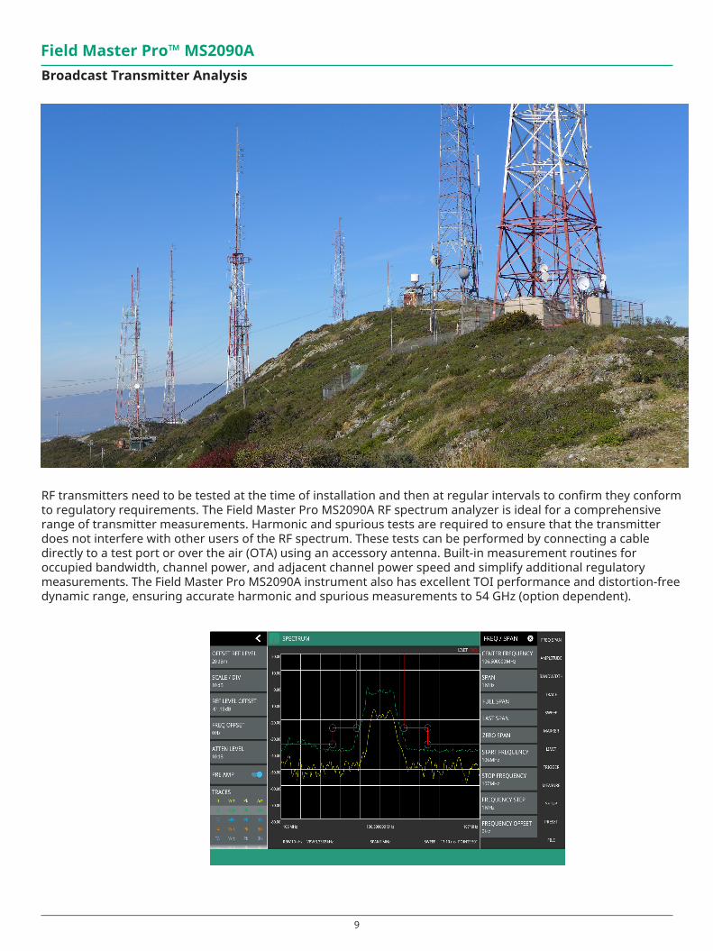
Field Master Pro™ MS2090ABroadcast Transmitter Analysis
RF transmitters need to be tested at the time of installation and then at regular intervals to confirm they conform to regulatory requirements. The Field Master Pro MS2090A RF spectrum analyzer is ideal for a comprehensive range of transmitter measurements. Harmonic and spurious tests are required to ensure that the transmitter does not interfere with other users of the RF spectrum. These tests can be performed by connecting a cable directly to a test port or over the air (OTA) using an accessory antenna. Built-in measurement routines for occupied bandwidth, channel power, and adjacent channel power speed and simplify additional regulatory measurements. The Field Master Pro MS2090A instrument also has excellent TOI performance and distortion-free dynamic range, ensuring accurate harmonic and spurious measurements to 54 GHz (option dependent).

10
Field Master Pro™ MS2090A
Microwave Radio LinksMicrowave radio links have become central building block of cellular and data networks. Installation crews need to align the radios over distances from a few tens of meters to several kilometers. The Field Master Pro MS2090A spectrum analyzer has frequency options to 54 GHz with exceptional sensitivity for dish alignment. Using a waveguide horn antenna, the power and modulation bandwidth can be verified at installation and during maintenance testing.
Satellite System MonitoringThe United Nations Office for Outer Space Affairs estimates there are close to 2,000 active satellites orbiting the earth. Each of these communicates with the ground through dedicated earth stations. Common frequencies for satellite communications have been in the 2 to 4 GHz bands and 4 to 8 GHz bands. Now new bands are opening up in the 12 to 18 GHz and 26 to 40 GHz bands, and even 36 to 50 GHz. As the number of satellites increases the opportunity for interference between all the communications increases. The Field Master Pro MS2090A is ideal for monitoring downlink signals to search for interference and noise.
Pulse Radar Measurements
The wide bandwidth of the MS2090A enables detailed analysis of pulsed radar signals. In zero span the de-fault bandwidth is 40 MHz and the minimum sweep time is 60 ns, and pulse rise time measurements as short as 20 ns are possible. Up to 12 markers can be positioned on the traces to simplify pulse repetition, pulse width and rise time measurements. In zero span a fixed frequency IF output option is also available to interface with external analysis tools.

11
Option 888 5G NR Base Station Measurements The rapid introduction of 5G NR networks requires an instrument that can validate the performance of the gNB base stations quickly in a field environment. In both the 3.5 GHz bands and the millimeter-wave (mmWave) 28 GHz and 39 GHz bands, the adoption of active antenna systems means that new test methods need to be considered. Some radios may have test monitor ports integrated, but many operators will make gNB transmitter measurements over-the-air (OTA).
The Field Master Pro MS2090A high-performance spectrum analyzer performs the essential measurements in full compliance with the 3GPP TS 38.104 V15. Measurements supported include:
• Frequency Error • Occupied Bandwidth
• Time Offset • Adjacent Channel Leakage Ratio
• Cell/Sector ID • Transmitter Spurious to 12.75 GHz
• Modulation Quality (EVM) • EIRP
• Unwanted Emissions • SS-RSRP, SS-RSRQ, SS-SINR
A key part of 5G NR signals is the synchronization signal block (SSB). Decoding the SSB can reveal the important cell characteristics, like cell ID, frequency error, and beam powers. Making measurements on the SSB allows transmitter testing on a live gNB. As well as displaying beam ID, the RSRP is graphed for each of the beams in the SSB. In order to properly decode the signal, the user must know center frequency, bandwidth, and subcarrier spacing of the signal under test. This can be entered manually or by using a 3GPP defined band and ARFCN. It is also critical to know the the frequency position of the SSB relative to the center frequency of the signal. This can also be entered manually as an offset from center or by entering the GSCN. In cases where the SSB location is unknown, the MS2090A has an Auto SSB Detect feature that searches the 3GPP defined raster of potential SSB positions to find it automatically.
Field Master Pro™ MS2090A
Field Master Pro MS2090A displays RSRP vs beam index based on OTA analysis of the 5G NR SSB

12
Where direct access to an RF test connector is not possible, 5G NR installation testing must be performed over the air with a directional antenna or waveguide horn antenna. Because the SSB is always transmitted, the easiest way to test an active gNB is to make measurements on these elements. The Field Master Pro MS2090A decodes all active beams in the signal, typically 8 beams for radios in the 3 to 6 GHz bands, and 12 to 64 beams in the mm wave bands around 28 GHz and 39 GHz. A measurement summary screen displays all the essential results to validate base station performance.
In cases where multiple cells are present, it may be helpful to use an omnidirectional antenna to measure the relative power of the different cells and track handover points where the power of two cells is close to equal. The MS2090A offers a Multi PCI measurement which utilizes advanced software processing to detect all active beams in a given location. The PCI, RSRP, SINR, and EVM of each beam is returned and can then be displayed as an RSRP histogram to monitor relative power, or as a table to summarize all results.
Field Master Pro™ MS2090A
MS2090A offers Multi PCI measurements for OTA testing of one or more 5G NR gNB
5G Radio
Multi PCI Beams
MS2090A Field Master Pro
5G Radio
OmnidirectionalAntenna

13
OTA SEM measurement on a 5G NR transmission with pass/fail results
A range of 3GPP-compliant spectrum measurements are supported. To measure gNB transmit power, the Field Master Pro MS2090A instrument includes EIRP and channel power measurements. Both are made OTA using a waveguide horn or broadband antenna to receive the signal. In cases where the gNB can be put into test modes and test model waveforms transmitted, a gated sweep feature enables measurements to be made on defined symbols in the 5G frame. Occupied bandwidth (OBW), adjacent channel power (ACP), and spectral emission mask (SEM) measurements have pre-configured setups to speed testing.
Field Master Pro™ MS2090A

14
Field Master Pro™ MS2090A
5G Coverage MappingCoverage mapping provides a clear representation of the signal strength of 5G transmitters over intended geographic area. The Field Master Pro MS2090A spectrum analyzer is configured to continuously measure RF data including 5G channel power, EIRP, or RSRP. When used with the NEON® MA8100A Signal Mapper, the results are graphically displayed on a digital map or building floor plan. The NEON MA8100A supports outdoor coverage mapping using GPS coordinates taken from the Field Master Pro MS2090A instrument’s built-in GNSS receiver and indoor coverage mapping using the NEON Tracking Unit.
The NEON MA8100A solution consists of a NEON Tracking Unit, NEON Signal Mapper Software for Android devices, and NEON Command Software for a PC. For indoor coverage mapping, the NEON Tracking Unit supports the collection and processing of sensor data that delivers 3D location information. The NEON Tracking Unit connects to the NEON Signal Mapper application that is run on an Android device. The NEON Signal Mapper application provides an intuitive Android user interface, enabling lightly trained users to map RF signals within buildings. RF data is captured by Field Master Pro MS2090A unit and the data is sent to the Android device. For outdoor coverage mapping applications, the Field Master Pro MS2090A instrument provides both location and RF data directly to the Android device. When in 5G demod mode, for each data point the application shows which SSB beam was recording the highest signal level.
12 markers facilitate the rapid identification and analysis of all signals on the screen. Delta and fixed The combined spectrum and spectrogram display shows activity over time in a given spectrum band. In dynamic environments, such as the 2.4 GHz ISM band, and WiFi activity can be recorded over time to assess the spectral occupancy. Six cursers positioned in the spectrogram time domain define the active spectrum traces.
Typical result screen for indoor coverage mapping Typical result screen for outdoor coverage mapping

15
Key Features
Multiple Traces and DetectorsUp to 6 traces can be displayed simultaneously, with each trace able to use different detector and averaging. Each trace is color-coded with an information table highlighting the detector type, averaging and status of each active trace.
Comprehensive Markersmarkers, with detailed results table, enable recording and archiving of results. A noise maker can be activated for noise power measurements in a 1 Hz bandwidth, and each marker can be set to initiate a true frequency count at the end of a sweep. Double tap a marker to open peak search options.
Limit Lines with Pass/FailFlexible limits, from simple maximum level lines to complex envelope shapes, provide automated pass/fail indication and can be used to trigger remote alarms. Limits can be entered manually to conform to international standards or automatically generated based on the signals measured in the current trace. Save on event facilitates the capture of intermittent interferers by storing a trace each time a limit line is violated.
Field Master Pro™ MS2090A
16
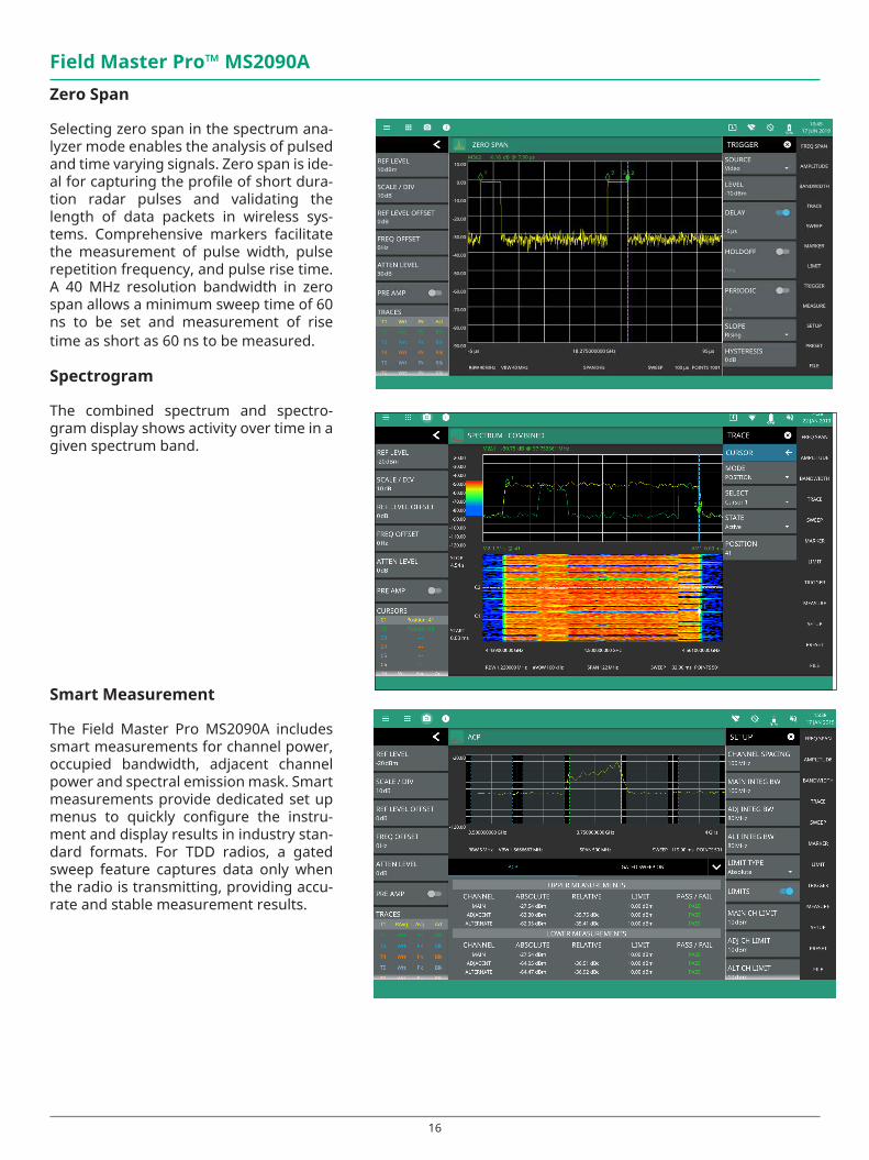
Field Master Pro™ MS2090AZero Span
Selecting zero span in the spectrum ana-lyzer mode enables the analysis of pulsed and time varying signals. Zero span is ide-al for capturing the profile of short dura-tion radar pulses and validating the length of data packets in wireless sys-tems. Comprehensive markers facilitate the measurement of pulse width, pulse repetition frequency, and pulse rise time. A 40 MHz resolution bandwidth in zero span allows a minimum sweep time of 60 ns to be set and measurement of rise time as short as 60 ns to be measured.
Spectrogram
The combined spectrum and spectro-gram display shows activity over time in a given spectrum band.
Smart Measurement
The Field Master Pro MS2090A includes smart measurements for channel power, occupied bandwidth, adjacent channel power and spectral emission mask. Smart measurements provide dedicated set up menus to quickly configure the instru-ment and display results in industry stan-dard formats. For TDD radios, a gated sweep feature captures data only when the radio is transmitting, providing accu-rate and stable measurement results.

17
Field Master Pro™ MS2090A
Real-Time Spectrum Analyzer (option)
The Real-Time Spectrum Analyzer (RTSA) op-tion provides real-time signal capture with 110 MHz bandwidth and the ability to cap-ture signals down to 2.05 µs duration with 100% probability of intercept (POI). This pro-vides unrivalled insight into interference in the wireless spectrum, capturing interfering signals that are too short in duration to be seen with conventional spectrum analyzers but may be degrading system performance. A power spectral density display shows the relative time that RF power is present at all levels and frequencies within the capture span. This is a powerful tool to find interfer-ing signals within the same band as known/wanted signals. The spectrogram displays the maximum output of the RTSA FFT over time with settable 50 ms to 5 seconds reso-lution. Spectrogram provides a history of spectral activity enabling intermittent inter-feres to be detected and recorded.
� WiFi (f;-
Field Master Pro MS2090A Laptop PC
(in Hot Spot Mode)
Wirelessly control Field Master Pro MS2090A from a PC
Ethernet and WiFi ConnectivityFull remote control of all instrument functions are availability using the standard Ethernet interface. The Field Master Pro MS2090A conforms to standard SCPI protocols. 802. 11b/g/a/n connectivity is also supported. This MS2090A connets to WiFi routers enabling remote control of the instrument using IP protocols. A remote destop tool comes standard with the Field Master Pro Ms2090A solution, enabling control of the device over an internet and WiFi connection from any location.

18
Field Master Pro™ MS2090AComprehensive Interface Selection The Field Master Pro MS2090A spectrum analyzer comes standard with: 3 x USB 3.0 type A host ports; 1 x USB 3.0 Type C device port; and, Data Out and microSD interfaces. USB 3.0 host interfaces can be used to save screen images as a .png file, IQ data files, and facilitate software and option updates. USB Type C, Data Out, microSD, and headphone jack interfaces are provided to support future applications.
USB 3.0/USB Type C for external devices
Data Out for high-speed data port for streaming (future application)
Aux headphone jack
IF Out
Configurable reference and trigger ports
GPS
Bias voltage 2x USB 3.0RF input (up to 54 GHz)
Ethernet for remote operation
microSD for extended storage
19
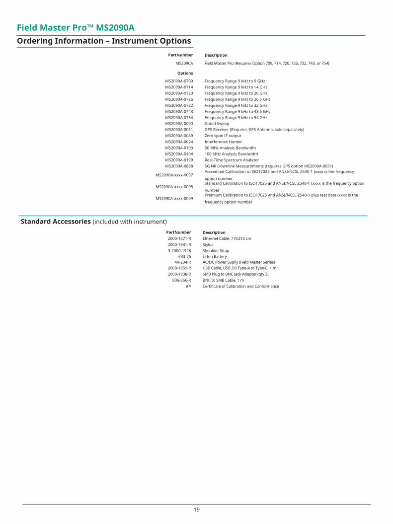
PartNumber Description
MS2090A Field Master Pro (Requires Option 709, 714, 720, 726, 732, 743, or 754)
Options
MS2090A-0709 Frequency Range 9 kHz to 9 GHzMS2090A-0714 Frequency Range 9 kHz to 14 GHzMS2090A-0720 Frequency Range 9 kHz to 20 GHzMS2090A-0726 Frequency Range 9 kHz to 26.5 GHzMS3090A-0732 Frequency Range 9 kHz to 32 GHzMS2090A-0743 Frequency Range 9 kHz to 43.5 GHzMS2090A-0754 Frequency Range 9 kHz to 54 GHzMS2090A-0090 Gated SweepMS2090A-0031 GPS Receiver (Requires GPS Antenna, sold separately)MS2090A-0089 Zero span IF outputMS2090A-0024 Interference HunterMS2090A-0103 50 MHz Analysis BandwidthMS2090A-0104 100 MHz Analysis BandwidthMS2090A-0199 Real-Time Spectrum AnalyzerMS2090A-0888 5G NR Downlink Measurements (requires GPS option MS2090A-0031)
MS2090A-xxxx-0097Accredited Calibration to ISO17025 and ANSI/NCSL Z540-1 (xxxx is the frequency
option number
MS2090A-xxxx-0098Standard Calibration to ISO17025 and ANSI/NCSL Z540-1 (xxxx is the frequency option
number
MS2090A-xxxx-0099Premium Calibration to ISO17025 and ANSI/NCSL Z540-1 plus test data (xxxx is the
frequency option number
Standard Accessories (included with instrument)
PartNumber Description2000-1371-R Ethernet Cable, 7 ft/213 cm2000-1931-R Stylus3-2000-1928 Shoulder Strap
633-75 Li-Ion Battery40-204-R AC/DC Power Suplly (Field Master Series)
2000-1859-R USB Cable, USB 3.0 Type-A to Type-C, 1 m2000-1938-R SMB Plug to BNC Jack Adapter (qty 3)
806-366-R BNC to SMB Cable, 1 m## Certificate of Calibration and Conformance
Field Master Pro™ MS2090AOrdering Information – Instrument Options

20
Field Master Pro™ MS2090A
Optional Accessories
Miscellaneous AccessoriesPart Number Description
2000-1945-R MS2090A Soft Case67135 Anritsu Backpack (for Handheld Instrument and PC)
760-243-R Large Transit Case with Wheels and Handle (56 cm x 45.5 cm x 26.5 cm (22.07" x 17.92" x 10.42")
40-207-R Automotive DC/DC Power Adapter (Field Master Series)2000-1374 External Dual Chager for Li-Ion BatteriesMA25401A Atomic Clock External 10 MHz Frequency Reference (see 11410-01134 for details)
GPS AntennasPart Number Description
2000-1528-R GPS Antenna, SMA(m) with 5 m (15 ft) cable, requires 5 VDC2000-1652-R GPS Antenna, SMA(m) with 0.3 m (1 ft) cable, requires 3.3 VDC or 5 VDC2000-1760-R GPS Antenna, SMA(m), 25 dB gain, 2.5 VDC to 3.7 VDC
Mag Mount and Broadband AntennasPart Number Description
2000-1616-R 20 MHz to 21000 MHz, N(f), 50 Ω2000-1645-R 694 MHz to 894 MHz, 3 dBi peak gain
1700 MHz to 2700 MHz, 3 dBi peak gain, N(m), 50 Ω, 10 ft2000-1646-R 750 MHz to 1250 MHz, 3 dBi peak gain,
1650 MHz to 2000 MHz, 5 dBi peak gain, 2100 MHz to 2700 MHz, 5 dBi peak gain, N(m), 50 Ω, 10 ft
2000-1647-R Cable 1: 698 MHz to 1200 MHz, 2 dBi peak gain, 1700 MHz to 2700 MHz, 5 dBi peak gain, N(m), 50 Ω, 10 ft Cable 2: 3000 MHz to 6000 MHz, 5 dBi peak gain, N(m), 50 Ω, 10 ftCable 3: GPS 26 dB gain, SMA(m), 50 Ω, 10 ft
2000-1648-R 1700 MHz to 6000 MHz, 3 dBi peak gain, N(m), 50 Ω, 10 ft
Directional AntennasPart Number Description
2000-1411-R 824 MHz to 896 MHz, N(f), 12.3 dBi, Yagi2000-1412-R 885 MHz to 975 MHz, N(f), 12.6 dBi, Yagi2000-1413-R 1710 MHz to 1880 MHz, N(f), 12.3 dBi. Yagi2000-1414-R 1850 MHz to 1990 MHz, N(f), 11.4 dBi, Yagi2000-1415-R 2400 MHz to 2500 MHz, N(f), 14.1 dBi, Yagi2000-1416-R 1920 MHz to 2170 MHz, N(f), 14.3 dBi, Yagi2000-1659-R 698 MHz to 787 MHz, N(f), 10.1 dBi, Yagi2000-1660-R 1425 MHz to 1535 MHz, N(f), 14.3 dBi, Yagi2000-1715-R Directional Antenna, 698 MHz to 2500 MHz, N(f), gain of 2 dBi to 10 dBi, typical2000-1726-R Antenna, 2500 MHz to 2700 MHz, N(f), 14.1 dBi, Yagi2000-1747-R Antenna, Log Periodic, 300 MHz to 7000 MHz, N(f), 5.1 dBi, typical2000-1748-R Antenna, Log Periodic, 1 GHz to 18 GHz, N(f), 6 dBi, typical2000-1777-R Portable Directional Antenna, 9 kHz to 20 MHz, N(f)2000-1778-R Portable Directional Antenna, 20 MHz to 200 MHz, N(f)2000-1779-R Portable Directional Antenna, 200 MHz to 500 MHz, N(f)2000-1812-R Portable Yagi Antenna, 450 MHz to 512 MHz, N(f), 7.1 dBi2000-1825-R Portable Yagi Antenna, 380 MHz to 430 MHz, N(f), 7.1 dBi

21
Portable AntennasPart Number Description
2000-1200-R 806 MHz to 866 MHz, SMA(m), 50 Ω2000-1473-R 870 MHz to 960 MHz, SMA(m), 50 Ω2000-1035-R 896 MHz to 941 MHz, SMA(m), 50 Ω (1/2 wave)2000-1030-R 1710 MHz to 1880 MHz, SMA(m), 50 Ω (1/2 wave)2000-1474-R 1710 MHz to 1880 MHz with knuckle elbow (1/2 wave)2000-1031-R 1850 MHz to 1990 MHz, SMA(m), 50 Ω (1/2 wave)2000-1475-R 1920 MHz to 1980 MHz and 2110 MHz to 2170 MHz, SMA(m), 50 Ω2000-1032-R 2400 MHz to 2500 MHz, SMA(m), 50 Ω (1/2 wave)2000-1361-R 2400 MHz to 2500 MHz, 5000 MHz to 6000 MHz, SMA(m), 50 Ω2000-1751-R 698 MHz to 960 MHz, 1710 MHz to 2100 MHz, 2500 MHz to 2700 MHz, SMA(m), 2 dB,
typical, 50 Ω2000-1636-R Antenna Kit (Consists of: 2000-1030-R, 2000-1031-R, 2000-1032-R, 2000-1200-R, 2000-
1035-R, 2000-1361-R, and carrying pouch)
Directional Horn AntennasPart Number Description
2000-1867-R 17.6 GHz to 26.7 GHz, WR42, 25 dBi gain2000-1868-R 26.4 GHz to 40.1 GHz, WR28, 25 dBi gain2000-1869-R 33.0 GHz to 50.1 GHz, WR22, 25 dB gain2000-1870-R 39.3 GHz to 59.7 GHz, WR19, 25 dBi gain
AttenuatorsPart Number Description
3-1010-122 20 dB, 5 W, DC to 12.4 GHz, N(m) to N(f)42N50-20 20 dB, 5 W, DC to 18 GHz, N(m) to N(f)
42N50A-30 30 dB, 50 W, DC to 18 GHz, N(m) to N(f)3-1010-123 30 dB, 50 W, DC to 8.5 GHz, N(m) to N(f)
1010-127-R 30 dB, 150 W, DC to 3 GHz, N(m) to N(f)
1010-121 Attenuator, 40 dB, 100 W, DC-18 GHz, N(f) input - N(m) output, UniDirectional
3-1010-124 Attenuator, 40 dB, 100 W, DC-8.5 GHz, N(f) input - N(m) output, Uni-directional
1010-128-R 40 dB, 150 W, DC to 3 GHz, N(m) to N(f)

22
Field Master Pro™ MS2090A
Optional Accessories (continued)
Bandpas FiltersPart Number Description
1030-114-R 806 MHz to 869 MHz, N(m) to SMA(f), 50 Ω1030-109-R 824 MHz to 849 MHz, N(m) to SMA(f), 50 Ω1030-110-R 880 MHz to 915 MHz, N(m) to SMA(f), 50 Ω1030-111-R 1850 MHz to 1910 MHz, N(m) to SMA(f), 50 Ω
1030-112-R 2400 MHz to 2484 MHz, N(m) to SMA(f), 50 Ω
1030-105-R 890 MHz to 915 MHz, N(m) to N(f), 50 Ω
1030-106-R 1710 MHz to 1790 MHz, N(m) to N(f), 50 Ω
1030-107-R 1910 MHz to 1990 MHz, N(m) to N(f), 50 Ω
1030-149-R High Pass, 150 MHz, N(m) to N(f), 50 Ω
1030-150-R High Pass, 400 MHz, N(m) to N(f), 50 Ω
1030-151-R High Pass, 700 MHz, N(m) to N(f), 50 Ω
1030-152-R Low Pass, 200 MHz, N(m) to N(f), 50 Ω
1030-153-R Low Pass, 550 MHz, N(m) to N(f), 50 Ω
1030-155-R 2500 MHz to 2700 MHz, N(m) to N(f), 50 Ω
1030-178-R 1920 MHz to 1980 MHz, N(m) to N(f), 50 Ω
1030-179-R 777 MHz to 798 MHz, N(m) to N(f), 50 Ω
1030-180-R 2500 MHz to 2570 MHz, N(m) to N(f), 50 Ω
2000-1684-R 791 MHz to 821 MHz, N(m) to N(f), 50 Ω
2000-1734-R Bandpass Filter, 699 MHz to 715 MHz, N(m) and N(f), 50 Ω2000-1735-R Bandpass Filter, 776 MHz to 788 MHz, N(m) and N(f), 50 Ω
2000-1736-R Bandpass Filter, 815 MHz to 850 MHz, N(m) and N(f), 50 Ω
2000-1737-R Bandpass Filter, 1711 MHz to 1756 MHz, N(m) and N(f), 50 Ω
2000-1738-R Bandpass Filter, 1850 MHz to 1910 MHz, N(m) and N(f), 50 Ω
2000-1739-R Bandpass Filter, 880 MHz to 915 MHz, N(m) and N(f), 50 Ω
2000-1740-R Bandpass Filter, 1710 MHz to 1785 MHz, N(m) and N(f), 50 Ω
2000-1741-R Bandpass Filter, 1920 MHz to 1980 MHz, N(m) and N(f), 50 Ω
2000-1742-R Bandpass Filter, 832 MHz to 862 MHz, N(m) and N(f), 50 Ω
2000-1743-R Bandpass Filter, 2500 MHz to 2570 MHz, N(m) and N(f), 50 Ω
2000-1799-R Bandpass Filter, 2305 MHz to 2320 MHz, N(m) and N(f), 50 Ω

23
Field Master Pro™ MS2090A
Optional Accessories (continued)
Precision Fixed AttenuatorsPart Number Description
41KB-3 DC to 26.5 GHz, 1W, 3 dB, K(m) to K(f)41KB-6 DC to 26.5 GHz, 1W, 6 dB, K(m) to K(f)
41KB-10 DC to 26.5 GHz, 1W, 10 dB, K(m) to K(f)41KB-20 DC to 26.5 GHz, 1W, 20 dB, K(m) to K(f)
41KC-3 DC to 40 GHz, 1W, 3 dB, K(m) to K(f)41KC-6 DC to 40 GHz, 1W, 6 dB, K(m) to K(f)
41KC-10 DC to 40 GHz, 1W, 10 dB, K(m) to K(f)41KC-20 DC to 40 GHz, 1W, 20 dB, K(m) to K(f)
41V-3 DC to 65 GHz, 1W, 3 dB, V(m) to V(f)41V-6 DC to 65 GHz, 1W, 6 dB, V(m) to V(f)
41V-10 DC to 65 GHz, 1W, 10 dB, V(m) to V(f)41V-20 DC to 65 GHz, 1W, 20 dB, V(m) to V(f)
Precision AdaptersPart Number Description
34NN50A Precision Adapter, N(m) to N(m), DC to 18 GHz, 50 Ω34NFNF50 Precision Adapter, N(f) to N(f), DC to 18 GHz, 50 Ω
AdaptersPart Number Description
1091-26-R SMA(m) to N(m), DC to 18 GHz, 50 Ω
1091-27-R SMA(f) to N(m), DC to 18 GHz, 50 Ω
1091-80-R SMA(m) to N(f), DC to 18 GHz, 50 Ω
1091-81-R SMA(f) to N(f), DC to 18 GHz, 50 Ω
1091-172-R BNC(f) to N(m), DC to 1.3 GHz, 50 Ω
1091-417-R N(m) to QMA(f), DC to 6 GHz, 50 Ω
1091-418-R N(m) to QMA(m), DC to 18 GHz, 50 Ω
510-90-R 7/16 DIN(f) to N(m), DC to 7.5 GHz, 50 Ω
510-91-R 7/16 DIN(f) to N(f), DC to 7.5 GHz, 50 Ω
510-92-R 7/16 DIN(m) to N(m), DC to 7.5 GHz, 50 Ω
510-93-R 7/16 DIN(m) to N(f), DC to 7.5 GHz, 50 Ω
510-96-R 7/16 DIN(m) to 7/16 DIN (m), DC to 7.5 GHz, 50 Ω
510-97-R 7/16 DIN(f) to 7/16 DIN (f), DC to 7.5 GHz, 50 Ω
71693-R 7aRuggedized adapter, K(f) - N(f), DC to 18 GHz, 50 Ω
34NMDVFNF50 Precision NMD Adapter, DC to 18 GHz, V(f) to N(f), 50 Ω
510-102-R N(m) to N(m), DC to 11 GHz, 50 Ω, 90 degrees right angle2000-1938-R SMB Plug to BNC Jack Adapter

24
Coaxial AdaptersPart Number Description
2000-1880-R DC to 18 GHz, N(m) to V(f), 50 Ω2000-1881-R DC to 18 GHz, N(f) to V(f), 50 Ω
K222B DC to 40 GHz, K(f) to K(f), 50 Ω34VFK50 DC to 40 GHz, V(f) to K(m), 50 Ω
34VFKF50 DC to 40 GHz, V(f) to K(f), 50 Ω34VV506 DC to 65 GHz, V(m) to V(m), 50 Ω34VVF50 DC to 65 GHz, V(f) to V(m), 50 Ω4VFVF50 DC to 65 GHz, V(f) to V(f), 50 Ω
Precision Waveguide Coaxial Adapters (right angle)Part Number Description
35WR42KF 18 GHz to 26.5 GHz, WR42 to K(f)35WR28KF 26.5 GHz to 40 GHz, WR28 to K(f)35WR22VF 33 GHz to 50 GHz, WR22 to V(f)35WR19VF 40 GHz to 60 GHz, WR19 to V(f)35WR15VF 50 GHz to 65 GHz, WR15 to V(f)
Waveguide to Coaxial End Launch Adapters (straight through)Part Number Description
2000-1899-R 17.6 GHz to 26.7 GHz, WR42 to K(f)
2000-1890-R 26.4 GHz to 40.1 GHz, WR28 to K(f)
1091-460-R 17.6 GHz to 26.7 GHz, WR42 to V(f)
1091-459-R 26.4 GHz to 40.1 GHz, WR28 to V(f)
1091-458-R 33.0 GHz to 50.1 GHz, WR22 to V(f)
1091-457-R 39.3 GHz to 59.7 GHz, WR19 to V(f)
1091-456-R 49.9 GHz to 67.0 GHz, WR15 to V(f)
Test Port Cables (Armoured, Semi-rigid)Part Number Description
3670K50-1 DC to 40 GHz, K(f) to K(m), 30.5 cm (1 ft)
3670K50-2 DC to 40 GHz, K(f) to K(m), 61.0 cm (2 ft)
3670V50A-1 DC to 70 GHz, V(f) to V(m), 30.5 cm (1 ft)
3670V50A-2 DC to 70 GHz, V(f) to V(m), 61.0 cm (2 ft)
Field Master Pro™ MS2090A
Optional Accessories (continued)

® Anritsu All trademarks are registered trademarks of their respective owners. Data subject to change without notice. For the most recent specifications visit: www.anritsu.com
11410-01103, Rev. E Printed in United States 2019-10©2019 Anritsu Company. All Rights Reserved.
Anritsu utilizes recycled paper and environmentally conscious inks and toner.
• United States Anritsu Company450 Century Parkway, Suite 190, Allen, TX 75013 U.S.A. Phone: +1-800-Anritsu (1-800-267-4878)
• Canada Anritsu Electronics Ltd.700 Silver Seven Road, Suite 120, Kanata, Ontario K2V 1C3, Canada Phone: +1-613-591-2003 Fax: +1-613-591-1006
• Brazil Anritsu Electrônica Ltda.Praça Amadeu Amaral, 27 - 1 Andar 01327-010 - Bela Vista - Sao Paulo - SP - Brazil Phone: +55-11-3283-2511 Fax: +55-11-3288-6940
• Mexico Anritsu Company, S.A. de C.V.Blvd Miguel de Cervantes Saavedra #169 Piso 1, Col. Granada Mexico, Ciudad de Mexico, 11520, MEXICO Phone: +52-55-4169-7104
• United Kingdom Anritsu EMEA Ltd.200 Capability Green, Luton, Bedfordshire LU1 3LU, U.K. Phone: +44-1582-433200 Fax: +44-1582-731303
• France Anritsu S.A.12 avenue du Québec, Batiment Iris 1-Silic 612, 91140 VILLEBON-SUR-YVETTE, France Phone: +33-1-60-92-15-50 Fax: +33-1-64-46-10-65
• Germany Anritsu GmbHNemetschek Haus, Konrad-Zuse-Platz 1 81829 München, Germany Phone: +49-89-442308-0 Fax: +49-89-442308-55
• Italy Anritsu S.r.l.Via Elio Vittorini 129, 00144 Roma Italy Phone: +39-06-509-9711 Fax: +39-6-502-2425
• Sweden Anritsu ABIsafjordsgatan 32C, 164 40 KISTA, Sweden Phone: +46-8-534-707-00
• Finland Anritsu ABTeknobulevardi 3-5, FI-01530 VANTAA, Finland Phone: +358-20-741-8100 Fax: +358-20-741-8111
• Denmark Anritsu A/STorveporten 2, 2500 Valby, Denmark Phone: +45-7211-2200 Fax: +45-7211-2210
• Russia Anritsu EMEA Ltd. Representation Office in RussiaTverskaya str. 16/2, bld. 1, 7th floor. Moscow, 125009, Russia Phone: +7-495-363-1694 Fax: +7-495-935-8962
• Spain Anritsu EMEA Ltd. Representation Office in SpainEdificio Cuzco IV, Po. de la Castellana, 141, Pta. 5 28046, Madrid, Spain Phone: +34-915-726-761 Fax: +34-915-726-621
• United Arab Emirates Anritsu EMEA Ltd. Dubai Liaison Office902, Aurora Tower, P O Box: 500311- Dubai Internet City Dubai, United Arab Emirates Phone: +971-4-3758479 Fax: +971-4-4249036
• India Anritsu India Pvt Ltd.6th Floor, Indiqube ETA, No.38/4, Adjacent to EMC2, Doddanekundi, Outer Ring Road, Bengaluru – 560048, India Phone: +91-80-6728-1300 Fax: +91-80-6728-1301
• Singapore Anritsu Pte. Ltd.11 Chang Charn Road, #04-01, Shriro House Singapore 159640 Phone: +65-6282-2400 Fax: +65-6282-2533
• P. R. China (Shanghai) Anritsu (China) Co., Ltd.Room 2701-2705, Tower A, New Caohejing International Business Center No. 391 Gui Ping Road Shanghai, 200233, P.R. China Phone: +86-21-6237-0898 Fax: +86-21-6237-0899
• P. R. China (Hong Kong) Anritsu Company Ltd.Unit 1006-7, 10/F., Greenfield Tower, Concordia Plaza, No. 1 Science Museum Road, Tsim Sha Tsui East, Kowloon, Hong Kong, P. R. China Phone: +852-2301-4980 Fax: +852-2301-3545
• Japan Anritsu Corporation8-5, Tamura-cho, Atsugi-shi, Kanagawa, 243-0016 Japan Phone: +81-46-296-6509 Fax: +81-46-225-8352
• Korea Anritsu Corporation, Ltd.5FL, 235 Pangyoyeok-ro, Bundang-gu, Seongnam-si, Gyeonggi-do, 13494 Korea Phone: +82-31-696-7750 Fax: +82-31-696-7751
• Australia Anritsu Pty Ltd.Unit 20, 21-35 Ricketts Road, Mount Waverley, Victoria 3149, Australia Phone: +61-3-9558-8177 Fax: +61-3-9558-8255
• Taiwan Anritsu Company Inc.7F, No. 316, Sec. 1, NeiHu Rd., Taipei 114, Taiwan Phone: +886-2-8751-1816 Fax: +886-2-8751-1817
Specifications are subject to change without notice.