High-function General-purpose Inverters RX Series V1 type
44
1 High-function General-purpose Inverters RX Series V1 type Versatile for a Wide Range of Applications • Double rating VT 120%/1 min and CT 150% /1 min. • Drive Programming • LCD 5 line Digital Operator (Optional) • Fieldbus communications with optional unit EtherCAT, CompoNet TM and DeviceNet TM • Built-in EMC filter Performance Specifications Inverter 3G3RX-V1 3-phase 200-V Class CT: Heavy load rating VT: Light load rating 3-phase 200-V class Item Model name (3G3RX-) A2004-V1 A2007-V1 A2015-V1 A2022-V1 A2037-V1 A2055-V1 A2075-V1 A2110-V1 A2150-V1 A2185-V1 A2220-V1 A2300-V1 A2370-V1 A2450-V1 A2550-V1 Maximum applicable motor capacity (kW) CT 0.4 0.75 1.5 2.2 3.7 5.5 7.5 11 15 18.5 22 30 37 45 55 VT 0.75 1.5 2.2 3.7 5.5 7.5 11 15 18.5 22 30 37 45 55 75 Rated output capacity (kVA) 200V CT 1.0 1.7 2.5 3.6 5.7 8.3 11.0 15.9 22.1 26.3 32.9 41.9 50.2 63.0 76.2 VT 1.2 2.1 3.2 4.1 6.7 10.3 15.2 20.0 25.2 29.4 39.1 48.4 58.5 72.7 93.5 240V CT 1.2 2.0 3.1 4.3 6.8 9.9 13.3 19.1 26.6 31.5 39.4 50.2 60.2 75.6 91.4 VT 1.5 2.6 3.9 4.9 8.1 12.4 18.2 24.1 30.3 35.5 46.9 58.1 70.2 87.2 112.2 Rated input voltage 3-phase 200 V -15% to 240 V +10%, 50/60 Hz ±5% Rated input current (A) CT 3.3 5.5 8.3 12 18 26 35 51 70 84 105 133 160 200 242 VT 3.9 7.2 10.8 13.9 23 37 48 64 80 94 120 150 186 240 280 Rated output voltage 3-phase 200 to 240 V (Cannot exceed that of incoming voltage) Rated output current (A) CT 3.0 5.0 7.5 10.5 16.5 24 32 46 64 76 95 121 145 182 220 VT 3.7 6.3 9.4 12 19.6 30 44 58 73 85 113 140 169 210 270 EMC Noise Filter Built-in (EMC Directive EN61800-3 Category C3) Weight (kg) 3.5 3.5 3.5 3.5 3.5 6 6 6 14 14 14 22 30 30 43 Braking Resistor circuit Regenerative braking Built-in Braking Resistor circuit (separate Discharge Resistor) Separate Regenerative Braking Unit Min. connectable resistance (Ω) 50 50 35 35 35 16 10 10 7.5 7.5 5 --- Maximum leakage current (mA) EMC filter enabled 2.5 48 23 EMC filter disabled 0.1
Transcript of High-function General-purpose Inverters RX Series V1 type

1
High-function General-purpose Inverters
RX Series V1 typeVersatile for a Wide Range of Applications• Double rating VT 120%/1 min and CT 150% /1 min.• Drive Programming• LCD 5 line Digital Operator (Optional)• Fieldbus communications with optional unit
EtherCAT, CompoNetTM and DeviceNetTM
• Built-in EMC filter
Performance SpecificationsInverter 3G3RX-V13-phase 200-V Class CT: Heavy load rating VT: Light load rating
3-phase 200-V class
Item Model name (3G3RX-) A2004-V1 A2007-V1 A2015-V1 A2022-V1 A2037-V1 A2055-V1 A2075-V1 A2110-V1 A2150-V1 A2185-V1 A2220-V1 A2300-V1 A2370-V1 A2450-V1 A2550-V1
Maximum applicable motor capacity (kW)
CT 0.4 0.75 1.5 2.2 3.7 5.5 7.5 11 15 18.5 22 30 37 45 55
VT 0.75 1.5 2.2 3.7 5.5 7.5 11 15 18.5 22 30 37 45 55 75
Rated output capacity (kVA)
200VCT 1.0 1.7 2.5 3.6 5.7 8.3 11.0 15.9 22.1 26.3 32.9 41.9 50.2 63.0 76.2
VT 1.2 2.1 3.2 4.1 6.7 10.3 15.2 20.0 25.2 29.4 39.1 48.4 58.5 72.7 93.5
240VCT 1.2 2.0 3.1 4.3 6.8 9.9 13.3 19.1 26.6 31.5 39.4 50.2 60.2 75.6 91.4
VT 1.5 2.6 3.9 4.9 8.1 12.4 18.2 24.1 30.3 35.5 46.9 58.1 70.2 87.2 112.2
Rated input voltage 3-phase 200 V -15% to 240 V +10%, 50/60 Hz ±5%
Rated input current (A)CT 3.3 5.5 8.3 12 18 26 35 51 70 84 105 133 160 200 242
VT 3.9 7.2 10.8 13.9 23 37 48 64 80 94 120 150 186 240 280
Rated output voltage 3-phase 200 to 240 V (Cannot exceed that of incoming voltage)
Rated output current (A)CT 3.0 5.0 7.5 10.5 16.5 24 32 46 64 76 95 121 145 182 220
VT 3.7 6.3 9.4 12 19.6 30 44 58 73 85 113 140 169 210 270
EMC Noise Filter Built-in (EMC Directive EN61800-3 Category C3)
Weight (kg) 3.5 3.5 3.5 3.5 3.5 6 6 6 14 14 14 22 30 30 43
Braking Resistor circuit
Regenerative braking Built-in Braking Resistor circuit (separate Discharge Resistor) Separate Regenerative Braking
Unit
Min. connectable resistance (Ω) 50 50 35 35 35 16 10 10 7.5 7.5 5 ---
Maximum leakage current (mA)
EMC filter enabled 2.5 48 23
EMC filter disabled 0.1

High-function General-purpose Inverters RX-Series V1 type
2
3-phase 400-V Class CT: Heavy load rating VT: Light load rating
3-phase 400-V class
Item Model name (3G3RX-) A4004-V1 A4007-V1 A4015-V1 A4022-V1 A4037-V1 A4055-V1 A4075-V1 A4110-V1 A4150-V1 A4185-V1 A4220-V1
Maximum applicable motor capacity (kW)
CT 0.4 0.75 1.5 2.2 3.7 5.5 7.5 11 15 18.5 22
VT 0.75 1.5 2.2 3.7 5.5 7.5 11 15 18.5 22 30
Rated output capacity (kVA)
400VCT 1.0 1.7 2.6 3.6 6.2 9.6 13.1 17.3 22.1 26.3 33.2
VT 1.3 2.1 3.3 4.6 7.6 11.0 15.2 20.0 25.6 29.7 39.4
480VCT 1.2 2.0 3.1 4.4 7.4 11.6 15.7 20.7 26.6 31.5 39.9
VT 1.5 2.5 3.9 5.5 9.2 13.3 18.2 24.1 30.7 35.7 47.3
Rated input voltage 3-phase 380 V -15% to 480 V +10%, 50/60 Hz ±5%
Rated input current (A)CT 1.8 2.8 4.2 5.8 9.8 15 21 28 35 42 53
VT 2.1 4.3 5.9 8.1 13.3 20 24 32 41 47 63
Rated output voltage 3-phase 380 to 480 V (Cannot exceed that of incoming voltage)
Rated output current (A)CT 1.5 2.5 3.8 5.3 9.0 14 19 25 32 38 48
VT 1.9 3.1 4.8 6.7 11.1 16 22 29 37 43 57
EMC Noise Filter Built-in (EMC Directive EN61800-3 Category C3)
Weight (kg) 3.5 3.5 3.5 3.5 3.5 6 6 6 14 14 14
Braking Resistor circuit
Regenerative braking Built-in Braking Resistor circuit (separate Discharge Resistor)
Min. connectable resistance (Ω) 100 100 100 100 70 70 35 35 24 24 20
Maximum leakage current (mA)
EMC filter enabled 5 95 56
EMC filter disabled 0.2
3-phase 400-V class
Item Model name (3G3RX-) A4300-V1 A4370-V1 A4450-V1 A4550-V1 B4750-V1 B4900-V1 B411K-V1 B413K-V1
Applicable motor capacity(kW)
CT 30 37 45 55 75 90 110 132
VT 37 45 55 75 90 110 132 160
Rated output capacity (kVA)
400VCT 40.1 51.9 63.0 77.5 103.2 121.9 150.3 180.1
VT 48.4 58.8 72.7 93.5 110.8 135 159.3 200.9
480VCT 48.2 62.3 75.6 93.1 123.8 146.3 180.4 216.1
VT 58.1 70.6 87.2 112.2 133 162.1 191.2 241.1
Rated input voltage 3-phase 380 V -15% to 480 V +10%, 50/60 Hz ±5%
Rated input current (A)CT 64 83 100 121 164 194 239 286
VT 77 94 116 149 176 199 253 300
Rated output voltage 3-phase 380 to 480 V (according to the input voltage)
Rated output current (A)CT 58 75 91 112 149 176 217 260
VT 70 85 105 135 160 195 230 290
EMC Noise Filter Built-in (EMC Directive EN61800-3 Category C3)
Weight (kg) 22 30 30 30 55 55 70 70
Braking Resistor circuit
Regenerative braking Separate Regenerative Braking Unit
Min. connectable resistance (Ω) ---
Maximum leakage current (mA)
EMC filter enabled 560.2 (No enabled/disabled setting available)
EMC filter disabled 0.2

High-function General-purpose Inverters RX-Series V1 type
3
Function SpecificationsInverter 3G3RX-V1
Function name Specifications
Enclosure ratings IP20 (0.4 to 55 kW)IP00 (75 to 132 kW)
Control method Phase-to-phase sinusoidal modulation PWM
Output frequency range 0.1 to 400 Hz
Frequency precision Digital command: ±0.01% of the maximum frequency, Analog command: ±0.2% of the maximum frequency (25±10°C)
Frequency resolutionDigital setting: 0.01 HzAnalog setting: maximum frequency/4000(Terminal FV: 12 bits/0 to +10 V), (Terminal FE: 12 bits/-10 to 10 V), (Terminal FI: 12 bits/0 to 20 mA)
Voltage/Frequency characteristicsHeavy load rating (CT):V/f characteristics (constant torque, reduced torque, free V/f setting), sensorless vector con-
trol, 0-Hz sensorless vector control, sensor vector controlLight load rating (VT) :V/f characteristics (constant torque, reduced torque, free V/f setting), sensorless vector control
Overload current rating Heavy load rating (CT): 150%/60 s, 200%/3 s (180%/3 s for 75 kW or more)Light load rating (VT): 120%/60 s, 150%/5 s
Instantaneous overcurrent protection 200% of the value of heavy load rating (CT)
Acceleration/Deceleration time 0.01 to 3600 s (linear/curve selection)
Speed fluctuation Heavy load rating (CT): ±0.5% *1, *2
Light load rating (VT): ±0.5% *1
Carrier frequency adjustment range(For 0.4 to 55kW)Heavy load rating (CT): 0.5 to15 kHzLight load rating (VT): 0.5 to12 kHz
(For 75 to 132kW)Heavy load rating (CT): 0.5 to 10 kHzLight load rating (VT): 0.5 to 8 kHz
Starting torque
Sensor less vector control(For 0.4 to 55kW)Heavy load rating (CT): 200%/0.3 Hz *1
Light load rating (VT): 150%/0.5 Hz *1
(For 75 to 132kW)Heavy load rating (CT): 180%/0.3 Hz *1
Light load rating (VT): 120%/0.5 Hz *1
0-Hz sensorless vector control(For 0.4 to 55kW)Heavy load rating (CT): 150%/Torque at 0 Hz *3Light load rating (VT): No function available
(For 75 to132kW)Heavy load rating (CT): 130%/Torque at 0 Hz *3Light load rating (VT): No function available
External DC injection braking Operates when the starting frequency is lower than that in deceleration via the STOP command, when the frequency reference is lower than the operation frequency, or via an external input (braking power, time, and frequency are variable)
Protective functions
Overcurrent protection, Overvoltage protection, Undervoltage protection, Electronic thermal protection, Temperature error protection, Momentary power interruption/Power interruption protection, Input phase loss protection, Braking resistor overload protection, Ground-fault current detection at power-on, USP error, External trip, Emergency shutoff trip, CT error, Communication error, Option error, etc.
Input signal
Frequency settings
Standard Digital Operator Setting via keys
External signal *4 0 to 10 VDC, -10 to 10 VDC (Input impedance: 10 kΩ), 4 to 20 mA (Input impedance: 100 Ω)
External port Setting through RS-485 communications
Forward or Reverse operation/Stop
Standard Digital Operator RUN/STOP (Forward/reverse switched via parameter settings)
External signal Forward/Stop (Reverse/Stop available at the time of multi-functional input terminal allocation), 3-wire input available (at the time of control circuit terminal block allocation)
External port Setting through RS-485 communications
Multi-function input *58 terminals, NO/NC switchable, sink/source logic switchableHeavy load (CT): 8 functions can be selected from among 72Light load (VT): 8 functions can be selected from among 57
Thermistor input terminal 1 terminal (Positive/Negative temperature coefficient of resistance element switchable)
Output signal
Multi-function output *5
5 open collector output terminals: NO/NC switchable, sink/source logic switchable1 relay (SPDT contact) output terminal: NO/NC switchableHeavy load (CT): 6 functions can be selected from among 55Light load (VT): 6 functions can be selected from among 51
Multi-function monitor outputterminal
Analog voltage output (0 to 10 V) *6 , Analog current output (0 to 20 mA) *6 , Pulse train output (maximum frequency 3.6 kHz)
Display monitor Output frequency, Output current, Output torque, Frequency conversion value, Trip record, I/O terminal status, Electric power, etc.
Other functions
• Heavy load rating (CT)V/f free setting (7), Upper/lower frequency limit, Frequency jump, Curve acceleration/deceleration, Manual torque boost level/break, Energy-saving operation, Analog meter adjustment, Starting frequency, Carrier frequency adjust-ment, Electronic thermal function (free setting available), External start/end (frequency/rate), Analog input selection, Trip retry, Restart during momentary power interruption, Various signal outputs, Reduced voltage startup, Overload limit, Initialization value setting, Automatic deceleration at power-off, AVR function, Automatic acceleration/deceler-ation, Auto tuning (Online/Offline)
• Light load rating (VT)V/f free setting (7), Upper/lower frequency limit, Frequency jump, Curve acceleration/deceleration, Manual torque boost level/break, Energy-saving operation, Analog meter adjustment, Starting frequency, Carrier frequency adjust-ment, Electronic thermal function (free setting available), External start/end (frequency/rate), Analog input selection, Trip retry, Restart during momentary power interruption, Various signal outputs, Reduced voltage startup, Overload limit, Initialization value setting, Automatic deceleration at power-off, AVR function, Auto tuning (Online/Offline)
*1 Applicable in the sensorless vector control*2 Applicable in the 0-Hz sensorless vector control*3 Applicable in the 0 Hz sensorless vector control when using a motor one size smaller in capacity than the inverter*4 The maximum frequency is set to 9.8 V for a voltage input of 0 to 10 VDC and to 19.8 mA for an current input of 4 to 20 mA, respectively. If this causes any inconvenience, change the default datas.
*5 In the VT mode, the available functions are limited compared with the CT mode. The default setting and setting range of some functions also differ.*6 The analog voltage and current values for the multi-function monitor output terminals show values that can only be used as a guide for analog meter connection. The maximum output value may differ slightly from 10 V or 20 mA due to the variability of the analog output circuit. If this causes any inconvenience, refer to the RX series V1 type User's Manual. (Man.No.I578) to adjust the default settings.

High-function General-purpose Inverters RX-Series V1 type
4
*7 Complies with the test method specified in JIS C60068-2-6: 2010 (IEC 60068-2-6: 2007).*8 If the altitude is higher than 1,000 m, reduce the amount of heat generation because air density decreases by 1% with the increasing altitude by 100 m. For switching devices such as IGBTs, the amount of heat generation is proportional to the current flowing in the device and the applied voltage. Therefore, reduce the value of the rated current by 1% with the increasing altitude by 100 m to use a standard inverter. However, this is applicable to an altitude of 2,500 m or lower.
Components and FunctionsNote: Example of the 3G3RX-A2055-V1/A2075-V1/A2110-V1/A4055-V1/A4075-V1/A4110-V1
Open the terminal block cover to wire the main circuit terminal block and the control circuit terminal block. Moreover, you can open the front cover to mount option boards.
Operat-ing envi-ronment
Ambient operating temperature Heavy load rating (CT): −10 to 50°CLight load rating (VT): −10 to 40°C
Ambient storage temperature −20 to 65°C
Ambient operating humidity 20% to 90% (with no condensation)
Vibration resistance *7 5.9m/s2 (0.6G), 10 to 55Hz / 0.4 to 22kW2.94m/s2 (0.3G), 10 to 55Hz / 30 to 132kW
Application environment At a maximum altitude of 1,000 m (without corrosive gases or dust) *8
Options
PG Board Sensor vector control 3G3AX-PG01
EtherCAT Communication Unit 3G3AX-RX-ECT
CompoNetTM Communication Unit 3G3AX-RX-CRT-E
DeviceNetTM Communication Unit 3G3AX-RX-DRT-E
Other options Braking Resistor, AC reactor, DC reactor, Digital Operator, Digital Operator cables, Noise filter, Regenerative braking unit, etc.
Interna-tionalstandard
ECDirective
EMC Directive EN61800-3: 2004
Low Voltage Directive EN61800-5-1: 2003
UL/cUL UL508C
Function name Specifications
Digital Operator
Data Display
Front Cover
Spacer Cover
Terminal block Cover
Use this to set parameters, view various monitor data, run/stop the inverter, etc.
This displays the frequency reference value, outputfrequency, parameter set value, or other relevant data.
Remove this to mount option boards.
Remove this to mount optional units or 5-line LCD Digital Operator.
Remove this cover when wiring the terminal block.
Inverter 3G3RX-V1
Connector for mounting option board 1
Connector for mounting option board 2
Use this connector to mount the optional board.
Use this connector to mount the optional board or communications units.
Control circuit terminal blocksUse this to connect various digital/analog I/O signals for inverter control.
Backing plateCut off the cutout portions of this plate to connect power supply lines, signal lines, etc.
Main circuit terminal blockUse this to connect the inverter main power supply,motor, braking resistor, and other devices.

High-function General-purpose Inverters RX-Series V1 type
5
Connection Diagram
* Variable volume adjuster (2 kΩ 1/4 W or larger recommended)
DC reactor(optional)
3-phase 200 VAC3-phase 400 VAC
Frequency reference power supplyFrequency setting
unit 500 to 2 kΩ Frequency reference input (voltage)
Frequency reference input (current)Frequency reference common
Sequence input common
M
R/L1
+1 P/+2
Braking resistor(optional)
RBN/-
T/L3
R
T
Ro
To
S/L2
U/T1
W/T3
MB
MA
MC
P2Multi-function output 2
P3Multi-function output 3
P4Multi-function output 4
P5Multi-function output 5
PC
RS+
RS -
RP
RS -
AM
AMI
MP
Option 1
Option 2
Multi-function output common
Multi-function analog output (voltage output)Multi-function analog output (current output)Multi-function digital output (PWM output)
P1Multi-function output 1
Multi-function relay output *
Multi-function relay output common
V/T2
S1
FW
P24
PSC
S4
SC
Thermistor
TH
FS
FI
FC
FVFrequency reference auxiliary input (voltage) FE
S3S2
S5
For termination resistors
RS485 communicationS6
S7S8
Short-circuit wire
To wire the control circuitpower supply and main circuitpower supply separately, besure to remove the J51connector wire first.
Control circuitpower supply
J51
10 VDC10kΩ
10kΩ
100Ω
Multi-function input 1
Multi-function input 2
Multi-function input 3Multi-function input 4Multi-function input 5Multi-function input 6Multi-function input 7Multi-function input 8
24 VDC
100Ω
MCMCCB
Forward rotation command
Internal 24 VDC
Multi-function common
*
*

High-function General-purpose Inverters RX-Series V1 type
6
Dimensions (Unit: mm)
Inverter 3G3RX-V1
140
143
62
130
6
241
255
150
13080
79
164
130
241
4-M524.5
Two, 6 dia.3G3RX-A2004-V13G3RX-A2007-V13G3RX-A2015-V13G3RX-A2022-V13G3RX-A2037-V13G3RX-A4004-V13G3RX-A4007-V13G3RX-A4015-V13G3RX-A4022-V13G3RX-A4037-V1
246 260
189
210
79
169
7189
80
13.6
203
170
82
24.5
246
189
4-M6Two, 7 dia.3G3RX-A2055-V13G3RX-A2075-V13G3RX-A2110-V13G3RX-A4055-V13G3RX-A4075-V13G3RX-A4110-V1
79
273.4
24.5 80
229
390376
250229
7
229
376
4-M6
9.5 83
244
190
Two, 7 dia.
3G3RX-A2150-V13G3RX-A2185-V13G3RX-A2220-V13G3RX-A4150-V13G3RX-A4185-V13G3RX-A4220-V1

High-function General-purpose Inverters RX-Series V1 type
7
4-M8
368
79
45 80
195
265
310
510
265
510540
265
10
Two, 10 dia.3G3RX-A2300-V13G3RX-A4300-V1
300
550
250
4-M10
8032.5
79
277
520
12
390
300
520
300
Two, 12 dia.3G3RX-A2370-V13G3RX-A2450-V13G3RX-A4370-V13G3RX-A4450-V13G3RX-A4550-V1
Two, 12 dia.8072.5
4-M10
12
250
380480
79
352
380
670
380
670700
3G3RX-A2550-V1

High-function General-purpose Inverters RX-Series V1 type
8
700670
3008032.5
4-M10
79
357
12300390
300
670
270
Two, 12 dia3G3RX-B4750-V13G3RX-B4900-V1
480
740710
12380
710
380480
79
4-M10380
270
72.5 80Two, 12 dia3G3RX-B411K-V1
3G3RX-B413K-V1

High-function General-purpose Inverters RX-Series V1 type
9
Communication UnitRX-Series V1 type EtherCAT Communication Unit 3G3AX-RX-ECTThis is the communication unit to connect the High-function General-purpose Inverters RX-series V1 type to EtherCAT network.This communication unit passed the conformance test of EtherCAT.Note: 1. It is not possible to use a EtherCAT Communication Unit 3G3AX-RX-ECT with a RX-series (Model without "-V1").
2. Sysmac Studio can be used when using with NJ/NX-series Controller.To connect the NJ Controller, Sysmac Studio version 1.03 or higher is required.To connect the NX Controller, Sysmac Studio version 1.13 or higher is required.
Common Specifications
EtherCAT Communications Specifications
Dimensions (mm)
Item Specifications
Power supply Supplied from the inverter
Protective structure Open type (IP20)
Ambient operating temperature 10 to 50C
Ambient storage temperature 20 to 65C
Ambient operating humidity 20% to 90% RH (with no condensation)
Vibration resistance 5.9 m/s2 (0.6 G), 10 to 55 Hz
Application environment At a maximum altitude of 1,000 m (without corrosive gases or dust)
Weight 100 g max. (Shipping weight: approx. 200 g)
International standard
UL/cUL UL508C
EC Directives EMC Directive :EN61800-3Low Voltage Directive :EN61800-5-1
Item Specifications
Communications standard IEC 61158 Type12, IEC 61800-7 CiA 402 drive profile
Physical layer 100BASE-TX (IEEE802.3)
ConnectorRJ45 x 2 (shielded type)ECAT IN : EtherCAT inputECAT OUT : EtherCAT output
Communications media Category 5 or higher (cable with double, aluminum tape and braided shielding) is recommended.
Communications distance Distance between nodes: 100 m max.
Process data Fixed PDO mappingPDO mapping
Mailbox (CoE) Emergency messages, SDO requests, SDO responses, and SDO information
Distributed clock FreeRun mode (asynchronous)
LED display
L/A IN (Link/Activity IN) x 1L/A OUT (Link/Activity OUT) x 1RUN x 1ERR x 1
CiA402 drive profile Velocity mode
35.1 D
31.7 5.4
(2)
79.8
66.5 32.7
48.110.3
16.8
10.3 (105)
2
43.966.1
(68.1)
Status indicator(L/A IN, L/A OUT, RUN, ERR)
Communications connector(IN, OUT) FG cable
Rotary switches fornode address setting (X10, X1)
Communications connector(IN)
Communications connector(OUT)
Note: After the EtherCAT Communication Unit is installed, dimension D of the inverter increases by 35.1 mm.(Dimension D of the inverter varies depending on the capacity. Refer to the RX-series V1 type USER'S MANUAL (Cat.No.I578))

High-function General-purpose Inverters RX-Series V1 type
10
RX-Series V1 type CompoNetTM Communication Unit 3G3AX-RX-CRT-EThis is the communication unit to connect the High-function General-purpose Inverters RX-series V1 type to CompoNetTM network.Note: It is not possible to use a CompoNetTM Communication Unit 3G3AX-RX-CRT-E with a RX-series (Model without "-V1").
Common Specifications
CompoNetTM Communications Specifications
Dimensions (mm)
Item Specifications
Power supply Supplied from the inverter
Protective structure IP20
Ambient operating temperature −10 to 50°C
Ambient storage temperature −20 to 65°C
Ambient operating humidity 20% to 90% RH (with no condensation)
Vibration resistance 5.9 m/s2 (0.6 G), 10 to 55 Hz
Application environment At a maximum altitude of 1,000 m (without corrosive gases or dust)
Insulation resistance 500VAC (between isolated circuits)
Weight 100 g max. (Shipping weight: approx. 170 g)
International standard
UL/cUL UL508
EC Directives EN61800-3 : 2004 (2004/108/EC) Second environment, Category C3EN61800-5-1 : 2007 (2006/95/EC) SELV
Item Specifications
Slave type Word Slave Unit (Mixed)
Certification CompoNetTM Conformance Tested
CompoNetTM Profile AC Drive (0x02)
Communication power supply --- (External power not required)
Node Address 0 to 63, set with inverter parameter P190 or the rotary switches.
Baud rates supported4 Mbps, 3 Mbps, 1.5 Mbps, 93.75 kbps. Automatically detecting baud rate of Master Unit
Default Connection path Supported, set with inverter parameter P046
Supported Assemblies
Basic Remote IO (Output assembly 20, Input assembly 70)Extended Speed IO (21, 71)Extended Speed and Torque Control (123, 173)Special IO (100, 150)Extended Control IO (101, 151)Extended Control IO and Multi function IO monitor (101, 153)Flexible Format (139, 159)Extended Speed and Acceleration Control (110, 111)
EDS file Depending on the RX-series V1 type inverter model
1
23
45
6
78
90 1
23
45 6
78
90
79.8
66.5
48.1
43.968.966.1
31.7
32.7
9.435.1 D
LED indicators (MS, NS)
Fieldbus connector FG Cable
Rotary switches for nodeaddress setting (X10, X1)
Note: After the CompoNetTM Communication Unit is installed, dimension D of the inverter increases by 35.1 mm.(Dimension D of the inverter varies depending on the capacity. Refer to the RX-series V1 type USER'S MANUAL (Cat.No.I578))

High-function General-purpose Inverters RX-Series V1 type
11
RX-Series V1 type DeviceNetTM Communication Unit 3G3AX-RX-DRT-EThis is the communication unit to connect the High-function General-purpose Inverters RX-series V1 type to DeviceNetTM network.Note: It is not possible to use a DeviceNetTM Communication Unit 3G3AX-RX-DRT-E with a RX-series (Model without "-V1").
Common Specification
DeviceNetTM Communications Specifications
Dimensions (mm)
Item Specifications
Power supply Supplied from the inverter
Protective structure IP20
Ambient operating temperature −10 to 50°C
Ambient storage temperature −20 to 65°C
Ambient operating humidity 20% to 90% RH (with no condensation)
Vibration resistance 5.9 m/s2 (0.6 G), 10 to 55 Hz
Application environment At a maximum altitude of 1,000 m (without corrosive gases or dust)
Insulation resistance 500 VAC (between isolated circuits)
Weight 100 g max. (Shipping weight: approx. 170 g)
International standard
UL/cUL UL508
EC Directives EN61800-3 : 2004 (2004/108/EC) Second environment, Category C3EN61800-5-1 : 2007 (2006/95/EC) SELV
Item Specifications
Certification DeviceNetTM Conformance Tested
DeviceNetTM Profile AC Drive (0x02)
Supported connections
Remote I/O: Master-Slave connectionPollBit-StrobeCOSCyclicExplicit MessagesConform to DeviceNetTM specifications
Communication power supply 11 to 25VDC (MAX 50 mA, type 20 mA)
Unit device address range MAC ID 0 to 63, set with inverter parameter P192
Baud rates supported 125, 250, or 500 kbps. Automatically detects baud rate of Master Unit.
Default Connection path Supported, set with inverter parameter P046
Supported Assemblies
Basic Remote IO (Output assembly 20, Input assembly 70)Extended Speed IO (21, 71)Extended Speed and Torque Control (123, 173)Special IO (100, 150)Extended Control IO (101, 151)Extended Control IO and Multi function IO monitor (101, 153)Flexible Format (139, 159)Extended Speed and Acceleration Control (110, 111)In case the DeviceNetTM master is configured using user allocation, only the input /output pairs can be configured.
EDS file Depending on the RX-series V1 type inverter model
66.1
43.9
31.779.8
66.5 32.7
48.1
35.1 D
LED indicators (MS, NS)
Fieldbus connectorFG Cable
Note: After the DeviceNetTM Communication Unit is installed, dimension D of the inverter increases by 35.1 mm.(Dimension D of the inverter varies depending on the capacity. Refer to the RX-series V1 type USER'S MANUAL (Cat.No.I578))

High-function General-purpose Inverters RX-Series V1 type
12
Options
Regenerative Braking Unit 3G3AX-RBU@@Used with a Braking Resistor when the deceleration time of the motor is needed to be reduced in the 3G3RX.
SpecificationsBuilt-in Resistance Type (3G3AX-RBU21/-RBU22/-RBU41)
*1 To use the braking resistor (Model: 3G3AX-RAB/RBB/RBC) for the 400-V class regenerative braking unit, be sure to remove the built-in resistor and connect two resistors of the same model in series. Using a 400-V class regenerative braking unit with only a single braking resistor connected may cause damage to the braking resistor.
*2 Use DIP switches to set the number of connected units.*3 The built-in resistor has a thermal fuse. If the alarm terminals are not connected, the fuse may blow out in order to prevent the resistor from burning due to
overheating. If the fuse blows out, the built-in resistor must be replaced.
SpecificationsExternal resistor type (3G3AX-RBU23/-RBU24/-RBU42/-RBU43)
*1 To use the braking resistor (3G3AX-RAB/RBB/RBC) for the 400-V class regenerative braking unit, be sure to remove the built-in resistor and connect two resistors of the same model in series. Using a 400-V class regenerative braking unit with only a single braking resistor connected may cause damage to the braking resistor.
*2 Use DIP switches to set the number of connected units.
Class 3-phase 200-V class 3-phase 400-V class
Model name (3G3AX-) RBU21 RBU22 RBU41*1
Connection resistance 17 Ω min. 17 Ω min. 34 Ω min.
Operating voltage ON/OFF
ON : 362.5 ± 5 VOFF: 355 ± 5 V (−5% or −10% setting available)
ON : 725 ± 5 VOFF: 710 ± 5 V (−5% or −10% setting available)
Operation indication LED ON (Lit)
Parallel interlocking operation function*2 5 units max.
Built-in resistor
Internal resistance 120 W, 180 Ω 120 W, 20 Ω 120 W, 180 Ω × 2 in series
Allowable consecutive ON time 10 s max. 0.5 s max. 10 s max.
Allowable operation cycle Cycle 1/10(ON for 10 s, OFF for 90 s)
Cycle 1/80(ON for 0.5 s, OFF for 40 s)
Cycle 1/10(ON for 10 s, OFF for 90 s)
Power consumption Instantaneous 0.73 kWShort-time rating 120 W
Instantaneous 6.6 kWShort-time rating 120 W
Instantaneous 1.46 kWShort-time rating 240 W
Protectivefunction
Built-in resistor overheatprotection
• Cooling fin temperature Relay operates at approximately 200°C or higher.Recovers at approximately 170°C or lower.
• Built-in temperature fuse (recovery impossible)*3
• Rating of contact 250 V AC 200mA (R load)12 V DC 500mA (R load)42 V DC 200mA (R load)
• Minimum load 1mA (R load)
Operatingenvironment
Ambient temperature −10 to 50°CAmbient storage temperature −20 to 65°CAmbient operating humidity 20% to 90% (with no condensation)
Vibration 5.9 m/s2 (0.6G) 10 to 55 Hz
Location At a maximum altitude of 1,000 m (without corrosive gases or dust)
Paint color Munselle 5Y7/1 (cooling fan: aluminum ground color)
Class 3-phase 200-V class 3-phase 400-V class
Model name (3G3AX-) RBU23 RBU24 RBU42*1 RBU43*1
Discharge resistance
Continuous operation 6 Ω min. 4 Ω min. 24 Ω min. 12 Ω min.
Short-time/ operationAllowable operation cycle/Continuous ON time
4 Ω min.1/52 min
2 Ω min.1/52 min
10 Ω min.1/1010 s
6 Ω min.1/52 min
Operating voltage ON/OFFON: 362.5 ± 5 VOFF: 355 ± 5 V (−5% or −10% setting available)
ON: 725 ± 5 VOFF: 710 ± 5 V (−5% or −10% setting available)
Operation indication LED ON (Lit)
Maximum number of units operating in parallel*2 2 units max.
Protective functions
Internal power module overheat protection
Built-in relay specificationsCooling fin temperature Relay operates at approximately 100°C or higher.• Rating of contact : 240 V AC 3 A (R load)
36 V DC 2 A (R load)• Minimum load : 5 V DC 50 mA (R load)
Operating environment
Ambient temperature −10 to 50°CAmbient storage temperature −20 to 65°CAmbient operating humidity 20% to 90% (with no condensation)
Vibration 4.9 m/s2 (0.5G) 10 to 55 Hz
Location At a maximum altitude of 1,000 m (without corrosive gases or dust)
Paint color Munselle 5Y7/1 (cooling fan: aluminum ground color)
Connection Example
InverterRegenerativeBraking Unit Braking Resistor
RB
P
AL1 *
AL2 *
P
N
RB
P
1
2
R1
R2
P/+2
N/-1
* The alarm output terminals for the Regenerative Braking Unit.Provide a circuit to turn off the primary power supply for the Inverter when the temperature relay of the built-in resistor or optional Braking Resistor is activated.

High-function General-purpose Inverters RX-Series V1 type
13
Dimensions (Unit: mm)
Groundterminal (M5)
234
200
50
67101
171
300
254
127
275
275
Four, 8 dia.
Groundterminal (M5)
217
109
237258
258
160
45
5186
151
250
Groundterminal (M5)
Four, 8 dia.
95145
35
100
5
755
208 218
Two, 5 dia.
Groundterminal (M5)
217
160
45
5186
151
250
237258
258
109
Groundterminal (M5)
Four, 8 dia.
95
5
100
35
1455
208 218
75
Two, 5 dia.
3G3AX-RBU21/-RBU22/-RBU41 3G3AX-RBU23
3G3AX-RBU24 3G3AX-RBU42
3G3AX-RBU43

High-function General-purpose Inverters RX-Series V1 type
14
Braking Resistor 3G3AX-RBA/-RBB/-RBC@@@@Consumes the regenerative motor energy with a resistor to reduce deceleration time.
Specifications
* Built-in resistors are equipped with thermal fuses. If the alarm is not connected, the fuse may blow to prevent burnout due to overheating. If the fuse blows, the built-in resistor will need to be replaced.
ModelCompact type
(3G3AX-RBA )Standard type
(3G3AX-RBB )Medium capacity type
(3G3AX-RBC )
1201 1202 1203 1204 2001 2002 3001 4001 4001 6001 12001
ResistanceCapacity 120 W 200 W 300 W 400 W 400 W 600 W 1200 W
Resistance (Ω) 180 100 50 35 180 100 50 35 50 35 17
Allowable brakingfrequency (%) 5 2.5 1.5 1.0 10 7.5 7.5 7.5 10
Allowable continuousbraking time (s) 20 12 5 3 30 20 10
Weight (kg) 0.27 0.97 1.68 2.85 2.5 3.6 6.5
Fault detection function
Built-in thermal (Contact capacity: 240 V AC 2 A max.)Minimum current: 5 mA, Normally ON (NC contact)Built-in temperature fuse (recovery impossible)
Built-in temperature relay,Normally ON (NC contact)Contact capacity:240 V AC 3 A (R load),0.2 A (L load), 36 V DC 2 A (R load)
General specifications
Ambient operatingtemperature −10 to 50°C
Ambient storagetemperature −20 to 65°C
Ambient operatinghumidity 20% to 90% (RH) with no condensation
Vibration 5.9 m/s (0.6 G) 10 to 55 Hz Complies with JISC0911
Location At a maximum altitude of 1,000 m (without corrosive gases or dust)
Cooling method Self-cooling
Connection Example
Braking Resistor
P
RB
1 *
2 *
Inverter
P/+2
RB
* The alarm output terminals for the Braking Resistor.Provide a circuit to turn off the primary power supply for the Inverter when the temperature relay of the Braking Resistor is activated.

High-function General-purpose Inverters RX-Series V1 type
15
Dimensions (Unit: mm)
3G3AX-RBA 3G3AX-RBB
3G3AX-RBC4001
3G3AX-RBC120013G3AX-RBC6001
150
110
7
10 170
390 410390 410
100
70 150
150
280 300
5
5
100
70
500
1.2
20.5 max.
170
2-4.243
150
160 55
H1H2
L1
L4 L5 25
T
15 dia.
R3.5
10
L6
L3
L2 L6
R3.
5
W7
Two, 5 dia.
Two, 5 dia.Two, 7 dia.
ModelDimensions (mm)
L1 L2 L3 L4 L5 L6
3G3AX-RBB2001 310 295 160 55 70 7.5
3G3AX-RBB2002 310 295 160 55 70 7.5
3G3AX-RBB3001 470 455 320 55 70 7.5
3G3AX-RBB4001 435 422 300 50 60 6.5
ModelDimensions (mm) Weight
(kg)ScrewsizeH1 H2 W T
3G3AX-RBB2001 67 12 64 1.6 0.97
M3.53G3AX-RBB2002 67 12 64 1.6 0.97
3G3AX-RBB3001 67 12 64 1.6 1.68
3G3AX-RBB4001 94 15 76 2 2.85

High-function General-purpose Inverters RX-Series V1 type
16
Radio Noise Filter 3G3AX-ZCL@Connected to the inverter input/output cables to reduce noise coming into the inverter from the power supply line and noise flowing from the inverterinto the power supply line.
Specifications3G3AX-ZCL1
Specifications3G3AX-ZCL2
Note: Select options by the maximum applicable motor capacity of heavy and light load rating.
Dimensions (Unit: mm)
Connection Example
R
S
T
M
Motor
PowerSupply
Connect asclose as possible.
Note 1: Wind each of three phase wires in the same direction. 2: Can be used on both the input and output sides of the Inverter.
Inverter
U/T1
V/T2
W/T3
S/L2
T/L3
R/L1
Applicable Invertercapacity
(kW)
200 V class 400 V class
Input output Input output
Quan-tity
No. of turns
Quan-tity
No. of turns
Quan-tity
No. of turns
Quan-tity
No. of turns
0.2 1 4 1 4 1 4 1 4
0.4 1 4 1 4 1 4 1 4
0.75 1 4 1 4 1 4 1 4
1.5 1 4 1 4 1 4 1 4
2.2 1 4 1 4 1 4 1 4
3.0 1 4 1 4 1 4 1 4
3.7 1 4 1 4 1 4 1 4
4.0 1 4 1 4 1 4 1 4
5.5 1 4 1 4 1 4 1 4
7.5 1 4 1 4 1 4 1 4
11 1 4 1 4 1 4 1 4
15 1 4 1 4 1 4 1 4
ApplicableInvertercapacity
(kW)
200 V class 400 V class
Input output Input output
Quan-tity
No. of turns
Quan-tity
No. of turns
Quan-tity
No. of turns
Quan-tity
No. of turns
0.1 1 4 1 4 1 4 1 4
0.2 1 4 1 4 1 4 1 4
0.4 1 4 1 4 1 4 1 4
0.75 1 4 1 4 1 4 1 4
1.5 1 4 1 4 1 4 1 4
2.2 1 4 1 4 1 4 1 4
3.0 1 4 1 4 1 4 1 4
3.7 1 4 1 4 1 4 1 4
4.0 1 4 1 4 1 4 1 4
5.5 1 4 1 4 1 4 1 4
7.5 1 4 1 4 1 4 1 4
160
3-M4
26 max.
95max. Two, 5.5 dia.80±0.5
18129
85
180
(23)
10
14
7 x 14 long and round mounting hole
7 dia. mounting hole
7
83 35
32
78max.
12.5±0.3
39.5 dia.
7
72±0.5
3
3G3AX-ZCL1 3G3AZ-ZCL2

High-function General-purpose Inverters RX-Series V1 type
17
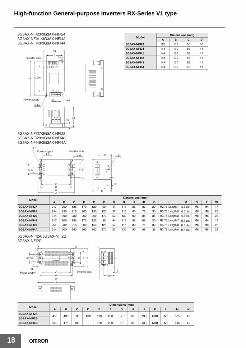
Input Noise Filter 3G3AX-NFI@@Reduces noise coming into the inverter from the power supply line and noise flowing from the inverter into the power supply line. Connect as closeto the Inverter as possible.
Specifications
Note: Select options by the maximum applicable motor capacity of heavy and light load rating.
Dimensions (Unit: mm)
Voltageclass
Max. applicable motor capacity
(kw)Model Max. input
voltage
Rated input current
(at 50°C)
Heat generation
(W)
Leakage current at 60 Hz
Case enclosure rating
Terminal size Wire diameter Weight
(kg)
200 Vclass
0.4, 0.75 3G3AX-NFI21
250V AC +10%
6A 3
1.5mA MAX (250V AC)
Plastic, IP00 M4 1.25 mm2 0.5
1.5 3G3AX-NFI22 10A 4 Plastic, IP00 M4 2 mm2 0.6
2.2, 3.7 3G3AX-NFI23 20A 6 Plastic, IP00 M4 2 mm2, 3.5 mm2 0.7
5.5 3G3AX-NFI24 30A 9 Plastic, IP00 M4 5.5 mm2 0.8
7.5 3G3AX-NFI25 40A 12 Plastic, IP00 M5 8 mm2 1.4
11 3G3AX-NFI26 60A 17 Plastic, IP00 M5 14 mm2 1.8
15 3G3AX-NFI27 80A 21 Metal, IP00 M6 22 mm2 3.6
18.5 3G3AX-NFI28 100A 23 Metal, IP00 M8 30 mm2 4.6
22, 30 3G3AX-NFI29 150A 45 Metal, IP00 M8 38 mm2, 60 mm2 9.0
37 3G3AX-NFI2A 200A 50 Metal, IP00 M10 100 mm2 or 38 mm2, 2 wires parallel
16
45 3G3AX-NFI2B 250A 68 Metal, IP00 M10 100 mm2 or 38 mm2, 2 wires parallel 16
55 3G3AX-NFI2C 300A 56 Metal, IP00 M10 150 mm2 or 60 mm2, 2 wires parallel 23
400 Vclass
0.4 to 2.2 3G3AX-NFI41
480V AC +10%
7A 2
7.5mA MAX (480V AC)
Plastic, IP00 M4 1.25 mm2, 2 mm2 0.7
3.7 3G3AX-NFI42 10A 4 Plastic, IP00 M4 2 mm2 0.7
5.5, 7.5 3G3AX-NFI43 20A 6 Plastic, IP00 M4 2 mm2, 3.5 mm2 0.7
11 3G3AX-NFI44 30A 9 Plastic, IP00 M4 5.5 mm2 0.8
15 3G3AX-NFI45 40A 12 Plastic, IP00 M5 8 mm2 1.4
18.5 3G3AX-NFI46 50A 15 Plastic, IP00 M5 14 mm2 1.6
22 3G3AX-NFI47 60A 17 Plastic, IP00 M5 14 mm2 1.8
30 3G3AX-NFI48 80A 21 Metal, IP00 M6 22 mm2 3.6
37 3G3AX-NFI49 100A 23 Metal, IP00 M8 38 mm2 4.6
45, 55 3G3AX-NFI4A 150A 45 Metal, IP00 M8 38 mm2, 60 mm2 9.0
Connection Example
L1'
L2'
L3'
Noise Filter Inverter
L1
L2
L3
M(Power Supply)
MotorU/T1
V/T2
W/T3
S/L2
T/L3
R/L1
Inverter side
66
52(10)
L3' L2' L1'
L3 L2 L1
(84) 100 117
Two, 5.0 dia. 10 M4
67MAX(15)
Power supply
Inverter side
6590
(16)
L1' L2' L3'
L1 L2 L3
155165
Two, 4.5 dia.
M6
(95)
Power supply
2-4.5×6
95
3G3AX-NFI213G3AX-NFI22
3G3AX-NFI25/3G3AX-NFI263G3AX-NFI45/3G3AX-NFI463G3AX-NFI47
High-function General-purpose Inverters RX-Series V1 type
18
Inverter side
Power supply
L3' L2' L1'
L3 L2 L1
(95)
74
(D)
5
M4
(15)73
C
BA
5 dia.
3G3AX-NFI23/3G3AX-NFI243G3AX-NFI41/3G3AX-NFI423G3AX-NFI43/3G3AX-NFI44
ModelDimensions (mm)
A B C D
3G3AX-NFI23 128 118 56 10
3G3AX-NFI24 144 130 56 11
3G3AX-NFI41 144 130 56 11
3G3AX-NFI42 144 130 56 11
3G3AX-NFI43 144 130 56 11
3G3AX-NFI44 144 130 56 11
ININ
Inverter side
A
6-N
G
Power supply
L1'
L2'
L3'L3 L2 L1
BCD
F EW
2-L 2-M
JH
J2
K
P
3G3AX-NFI27/3G3AX-NFI283G3AX-NFI29/3G3AX-NFI483G3AX-NFI49/3G3AX-NFI4A
ModelDimensions (mm)
A B C D E F G H J J2 K L M N P W
3G3AX-NFI27 217 200 185 170 120 90 44 115 85 82 20 R2.75 Length 7 5.5 dia. M6 M4 17
3G3AX-NFI28 254 230 215 200 150 120 57 115 80 75 30 R3.75 Length 8 6.5 dia. M8 M6 23
3G3AX-NFI29 314 300 280 260 200 170 57 130 90 85 35 R3.75 Length 8 6.5 dia. M8 M6 23
3G3AX-NFI48 217 200 185 170 120 90 44 115 85 82 20 R2.75 Length 7 5.5 dia. M6 M4 17
3G3AX-NFI49 254 230 215 200 150 120 57 115 80 75 30 R3.75 Length 8 6.5 dia. M8 M6 23
3G3AX-NFI4A 314 300 280 260 200 170 57 130 90 85 35 R3.75 Length 8 6.5 dia. M8 M6 23
ModelDimensions (mm)
A B C D E F G H J K L M N
3G3AX-NFI2A450 430 338 100 190 230 7 180 (133) M10 M8 385 1.0
3G3AX-NFI2B
3G3AX-NFI2C 500 475 400 - 160 200 12 180 (133) M10 M8 445 1.2
Inverter side
A
G
Power supply
L1'
L2'
L3'L3 L2 L1
B
C
FE
M
H
K K L
t
(J)
D86 39
3G3AX-NFI2A/3G3AX-NFI2B3G3AX-NFI2C

High-function General-purpose Inverters RX-Series V1 type
19
EMC Noise Filter 3G3AX-EFI@@@Separately installed option used to comply with the EC's EMC Directives. Select a filter appropriate for the Inverter model.Although an EMC Noise Filter is built into the RX, it may be necessary to provide another EMC Noise Filter when the cable between the Motor and the Inverter is long.
Specifications
Note: Select options by the maximum applicable motor capacity of heavy and light load rating.
Dimensions (Unit: mm)
Voltageclass
Max. applicablemotor capacity (kw)
ModelInput
current In (A)
Heat gener-ation (W)
Leakagecurrent
(480V AC) at 60 Hz
ClassCase
enclosure rating
Terminal size Wire dia. Weight
(kg)200 V class
400 V class
200 V class/400 V class
0.4, 0.75 0.4 to 2.2 3G3AX-EFI41 7 4 150mA MAX
A
Plastic, IP00
M41.25 mm2, 2 mm2 0.7
1.5 3.7 3G3AX-EFI42 10 4 150mA MAX 2 mm2 0.7
2.2, 3.7 5.5, 7.5 3G3AX-EFI43 20 8 170mA MAX
M5
2 mm2, 3.5 mm2 1.0
5.5 11 3G3AX-EFI44 30 9 170mA MAX 5.5 mm2 1.3
7.5 15 3G3AX-EFI45 40 15 170mA MAX 8 mm2 1.4
- 18.5 3G3AX-EFI46 50 15 250mA MAX
Metal, IP00
M6
14 mm2 2.9
11 22 3G3AX-EFI47 60 15 250mA MAX 14 mm2 3.0
15 30 3G3AX-EFI48 80 21 250mA MAX 22 mm2 3.6
18.5 37 3G3AX-EFI49 100 23 250mA MAXM8
30 mm2, 38 mm2 5.0
22, 30 45, 55 3G3AX-EFI4A 150 45 250mA MAX 38 mm2, 60 mm2 9.0
37 75, 90 3G3AX-EFI4B 200 50 250mA MAX M10 100 mm2 or 38 mm2, 2 wires parallel 16.0
Connection Example
L1 L1'
L2'
L3'
L2
L3
R/L1
S/L2
T/L3
U/T1
V/T2
W/T3M
(Power supply)
EMCNoise FilterMolded-case
Circuit BreakerMotor
Inverter
7456
144
73(15)
130 (95)
5
M411
(95) 155 165
(16)
65 95
90
5 dia.Two, 4.5 dia.
Protective ground terminals Two, 4.5×6
3G3AX-EFI413G3AX-EFI42
3G3AX-EFI43/3G3AX-EFI443G3AX-EFI45

High-function General-purpose Inverters RX-Series V1 type
20
L3L2
L1
L3'
L2'
L1'
86100
190230
39
7
338
430
(133)
180
450
M10
M10
M8
3G3AX-EFI4B
L3L2
L1
L3'
L2'
L1'
F E
D
C J
K
HB
6-N
P
2-M
A
2-L
3G3AX-EFI46/3G3AX-EFI47/3G3AX-EFI483G3AX-EFI49/3G3AX-EFI4A
ModelDimensions (mm)
A B C D E F H J K L M N P
3G3AX-EF146
217 220 185 170 120 90 115 85 20 R2.75Length 7 5.5 dia. M6 M43G3AX-EF147
3G3AX-EF148
3G3AX-EF149 254 230 215 200 150 120 115 80 30 R3.25Length 8 6.5 dia. M8 M6
3G3AX-EF14A 314 300 280 260 200 170 130 90 35 R3.25Length 8 6.5 dia. M8 M6

High-function General-purpose Inverters RX-Series V1 type
21
Output Noise Filter 3G3AX-NFO@@Reduces noise generated by the Inverter. Connect as close to the Inverter as possible.
Specifications
Note: Select options by the maximum applicable motor capacity of heavy and light load rating.
Dimensions (Unit: mm)
Max. applicable motor capacity (kW)Model Rated voltage Rated input current (A) Weight (kg)
200 V class 400 V class
0.4, 0.75 0.4 to 2.2 3G3AX-NFO01
500V AC
6 0.7
1.5, 2.2 3.7 3G3AX-NFO02 12 0.9
3.7, 5.5 5.5 to 11 3G3AX-NFO03 25 2.1
7.5, 11 15 to 22 3G3AX-NFO04 50 3.7
15 30, 37 3G3AX-NFO05 75 5.7
18.5, 22 45 3G3AX-NFO06 100 8.4
30, 37 55, 75 3G3AX-NFO07 150 9
Model A B C D E F G H J K L
3G3AX-NFO01 140 125 110 156 70 95 50 R: 2.25mmLength: 6mm 4.5 mm dia. M4 -
3G3AX-NFO02 160 145 130 176 80 110 70 R: 2.75mmLength: 7mm 5.5 mm dia. M4 -
3G3AX-NFO03 112 80 154 160 145 130 120 - 6.5 mm dia. M4 -
3G3AX-NFO04 162 100 210 200 180 160 150 - 6.5 mm dia. M5 M5
3G3AX-NFO05 182 100 230 220 200 180 170 - 6.5 mm dia. M6 M6
3G3AX-NFO06 182 100 237 220 200 180 170 - 6.5 mm dia. M8 M8
3G3AX-NFO07 202 150 257 240 220 200 170 - 6.5 mm dia. M8 M8
Connection Example
4
5
6
Noise Filter
1
2
3
M(Power supply)
MotorInverter
U/T1
V/T2
W/T3
S/L2
T/L3
R/L1
3G3AX-NFO013G3AX-NFO02
3G3AX-NFO03/3G3AX-NFO04/3G3AX-NFO053G3AX-NFO06/3G3AX-NFO07
DEF
K×6
K×6
J×2H
H
J×4
LDABC
BACE F
GG

High-function General-purpose Inverters RX-Series V1 type
22
DC Reactor 3G3AX-DL@@@@Used to suppress harmonic current generated from the Inverter.Suppresses harmonic current better than the AC Reactor and can be used with the AC Reactor.
Specifications
Note: Select options by the maximum applicable motor capacity of heavy and light load rating.
Voltageclass Model Figure
No.
Max. appli-cable motor
capacity(kW)
Dimensions (mm)Weight
(kg)
Standardapplicable
wireW D H A B X Y C K
200-Vclass
3G3AX-DL2004
1
0.4 66 90 98 - 95 56 72 5.2 x 8 M4 1.0 1.25 mm2 min.
3G3AX-DL2007 0.75 66 90 98 - 105 56 72 5.2 x 8 M4 1.3 1.25 mm2 min.
3G3AX-DL2015 1.5 66 90 98 - 115 56 72 5.2 x 8 M4 1.6 2 mm2 min.
3G3AX-DL2022 2.2 86 100 116 - 105 71 80 6 x 9 M4 2.1 2 mm2 min.
3G3AX-DL2037 3.7 86 100 118 - 120 71 80 6 x 9 M4 2.6 3.5 mm2 min.
3G3AX-DL2055
2
5.5 111 100 210 - 110 95 80 7 x 11 M5 3.6 8 mm2 min.
3G3AX-DL2075 7.5 111 100 212 - 120 95 80 7 x 11 M6 3.9 14 mm2 min.
3G3AX-DL2110 11 146 120 252 - 110 124 96 7 x 11 M6 6.5 22 mm2 min.
3G3AX-DL2150 15 146 120 256 - 120 124 96 7 x 11 M8 7.0 38 mm2 min.
3G3AX-DL2220
3
18.5, 22 120 175 356 140 145 98 151 7 x 11 M8 9.0 60 mm2 min.
3G3AX-DL2300 30 120 175 386 155 150 98 151 7 x 11 M8 13.0 38 mm2 x 2 min.
3G3AX-DL2370 37 120 175 390 155 150 98 151 7 x 11 M10 13.5 38 mm2 x 2 min.
3G3AX-DL2450 45 160 190 420 180 150 120 168 7 x 11 M10 19.0 60 mm2 x 2 min.
3G3AX-DL2550 55 160 190 424 180 180 120 168 7 x 11 M12 24.0 80 mm2 x 2 min.
400-Vclass
3G3AX-DL4004
1
0.4 66 90 98 - 85 56 72 5.2 x 8 M4 0.8 1.25 mm2 min.
3G3AX-DL4007 0.75 66 90 98 - 95 56 72 5.2 x 8 M4 1.1 1.25 mm2 min.
3G3AX-DL4015 1.5 66 90 98 - 115 56 72 5.2 x 8 M4 1.6 2 mm2 min.
3G3AX-DL4022 2.2 86 100 116 - 105 71 80 6 x 9 M4 2.1 2 mm2 min.
3G3AX-DL4037 3.7 86 100 116 - 120 71 80 6 x 9 M4 2.6 2 mm2 min.
3G3AX-DL4055 5.5 111 100 138 - 110 95 80 7 x 11 M4 3.6 3.5 mm2 min.
3G3AX-DL4075 7.5 111 100 138 - 115 95 80 7 x 11 M4 3.9 3.5 mm2 min.
3G3AX-DL41102
11 146 120 250 - 105 124 96 7 x 11 M5 5.2 5.5 mm2 min.
3G3AX-DL4150 15 146 120 252 - 120 124 96 7 x 11 M6 7.0 14 mm2 min.
3G3AX-DL4220
3
18.5, 22 120 175 352 140 145 98 151 7 x 11 M6 9.5 22 mm2 min.
3G3AX-DL4300 30 120 175 356 140 145 98 151 7 x 11 M8 9.5 30 mm2 min.
3G3AX-DL4370 37 120 175 386 155 150 98 151 7 x 11 M8 13.5 38 mm2 min.
3G3AX-DL4450 45 160 190 416 180 145 120 168 7 x 11 M8 16.5 60 mm2 min.
3G3AX-DL4550 55 160 190 416 190 170 120 168 7 x 11 M8 23.0 38 mm2 x 2 min.
Connection Example
DC Reactor
P
PD
Inverter
P/+2
+1

High-function General-purpose Inverters RX-Series V1 type
23
Dimensions (Unit: mm)
Fig. 1 Fig. 2 Fig. 3
Y
Y D
Max. H Max. H
D
2-K
W
4-C
Max.A Max. B
Max. H
2-K
X
Y D
Max. BMax. B2-K
WX
Ground terminal (M5)
Ground terminal (M6)4-C
X 4-CGround terminal (M4)W

High-function General-purpose Inverters RX-Series V1 type
24
AC Reactor 3G3AX-AL@@@@Connect the AC Reactor if the capacity of the power supply is much larger than that of the Inverter or the power factor is required to be improved.
Specifications
Note: Select options by the maximum applicable motor capacity of heavy and light load rating.
Dimensions (Unit: mm)
Voltage class ModelMax. applicable motor capacity
(kw)
Dimensions (mm) Weight(kg)A C D E H H1 X Y
200-Vclass
3G3AX-AL2025 0.4 to 1.5 120 82 60 40 150 94 50 67 2.8
3G3AX-AL2055 2.2, 3.7 120 98 60 40 150 94 50 75 4.0
3G3AX-AL2110 5.5, 7.5 150 103 70 55 170 108 60 80 5.0
3G3AX-AL2220 11, 15 180 113 75 55 190 140 90 90 10.0
3G3AX-AL2330 18.5, 22 180 113 85 60 230 140 125 90 11.0
3G3AX-AL2500 30, 37 260 113 85 60 290 202 100 90 19.0
3G3AX-AL2750 45, 55 260 144 110 80 290 207 125 112 25.0
400-Vclass
3G3AX-AL4025 0.4 to 1.5 130 82 60 40 150 94 50 67 2.7
3G3AX-AL4055 2.2, 3.7 130 98 60 40 150 94 50 75 4.0
3G3AX-AL4110 5.5, 7.5 150 116 75 55 170 106 60 98 6.0
3G3AX-AL4220 11, 15 180 103 75 55 190 140 100 80 10.0
3G3AX-AL4330 18.5, 22 180 123 85 60 230 140 100 100 11.5
3G3AX-AL4500 30, 37 260 113 85 60 290 202 100 90 19.0
3G3AX-AL4750 45, 55 260 146 110 80 290 207 125 112 25.0
Connection Example
AC ReactorR
S
T
R0
S0
T0
Inverter
M(Power supply)
MotorU/T1
V/T2
W/T3
S/L2
T/L3
R/L1
H max.
H1 max.
X Y
C max.
D max. E max.
A max.
R So S To TRo
A max.D max. E max.
X Y
C max.
H max.
H1 max.
R So S To TRo
A max.
X
H max.
H1 max.
D max. E max.
Y
C max.
Ro So ToR S T
Ro So ToR S T
H max.
H1 max.
X
A max.
D max. E max.
Y
C max.
3G3AX-AL20253G3AX-AL2055
3G3AX-AL4025/3G3AX-AL40553G3AX-AL4110
3G3AX-AL4220/3G3AX-AL43303G3AX-AL4500/3G3AX-AL4750
3G3AX-AL2110/3G3AX-AL22203G3AX-AL2330/3G3AX-AL2500/3G3AX-AL2750

High-function General-purpose Inverters RX-Series V1 type
25
PG Board 3G3AX-PG01The PG Board (3G3AX-PG01) is an optional board for the 3G3RX Series Inverter. With this board, you can realize highly accurate system operation with minimum speed fluctuation, and position control via pulse train position command input by detecting the rotation speed of the motor with an encoder and using the data for feedback.
Specifications
* The inverter setting or external input is available.
Item Specifications
Speed controlEncoder feedback Standard number of encoder pulses: 1024 pulses/r
Maximum input number of pulses: 100k pulses/s
Speed control system Proportional integral (PI)/ Proportional (P) control
Position controlPosition command
• The pulse train can be input in three modes.Mode 0: Pulse train with 90° phase differenceMode 1: Forward/Reverse command + Pulse trainMode 2: Forward pulse train + Reverse pulse trainThe input mode depends on the Inverter setting.
• Maximum input number of pulses: 100k pulses/s
Electronic gear • Pulse ratio A/B (A, B: 1 to 9999 can be set)• Available setting range: 1/50 ≤ A/B ≤ 20
OrientationStop position • 4096 divisions per one motor rotation *
Speed • Orientation speed and rotation direction settings available
Protective functions
• Encoder cable disconnection protection• Overspeed protection (Overspeed error detection level (P026))• Positioning error• 3G3AX-PG connection error
Connection Example
FS
FV
FC
EP5DC5V
EG5
EAP
EAN
EBP
EBN
EZP
EZN
SAP
SAN
SBP
SBN
AP
AN
BP
BN
TM1
Photo coupler
Photo coupler
Receiver IC
TM2
Receiver IC
Driver IC
Driver IC
Inverter control terminal PG BoardAvailable to allocate tomulti-function inputterminals 1 to 8
M
EC
Motor withan encoder
Pulse trainposition command
POK
ZS
DSE
Outputterminal
FW
RV
LAC
PCLR (Position deviation clear)
ORT
CM1
Inputterminal
Encoder signal output
STAT
Encoder signal
(LAD cancel)
(Orientation)
(Pulse train positioncommand inputpermission)
Available to allocate tomulti-functio output terminals 1 to 5
(Position ready)
(0 Hz signal)
(Excessive speeddeviation)
Photo coupler
Note: For the terminal connection on the Inverter, refer to the Inverter RX series V1 type User’s Manual (Man.No. I578).

High-function General-purpose Inverters RX-Series V1 type
26
Digital OperatorUsed to set parameters, perform various monitoring, and start and stop the Inverter.
3G3AX-OP01
Digital operator extension cable 3G3AX-OPCN@Used to install the Digital Operator away from the Inverter.
Data display
Operation keys
RUN commandLED indicator
FREQ adjuster
Dimensions Height (55 mm) × Width (70 mm) × Depth (10 mm)
Dimensions
3G3AX-OPCN1 (Cable length: 1 m)3G3AX-OPCN3 (Cable length: 3 m)

Ordering Information
■System Configuration.....................................................................................28
■Interpreting Model Numbers ..........................................................................29
■Ordering Information
RX series V1 type Inverter Models ..............................................................29Communication Unit ....................................................................................30Related Options ...........................................................................................30Recommended EtherCAT Communications Cables....................................37Software.......................................................................................................38Communications Cable................................................................................38
■Overview of Inverter Selection .......................................................................39
■Related Manuals ............................................................................................43
■Other Products in the Inverter Series.............................................................43
Sysmac® is a trademark or registered trademark of OMRON Corporation in Japan and other countries for OMRON factory automation products.Windows is either registered trademarks or trademarks of Microsoft Corporation in the United States and/or other countries.EtherCAT® is registered trademark and patented technology, licensed by Beckhoff Automation GmbH, Germany.CompoNetTM, DeviceNetTM and CIP SafetyTM on EtherNet/IP are the trademarks of ODVA.Other company names and product names in this document are the trademarks or registered trademarks of their respective companies.

High-function General-purpose Inverters RX-Series V1 type
28
System Configuration
PG Board3G3AX-PG01
Machine Automation ControllerNJ/NX-series
Programmable ControllerCJ2/CJ1
Programmable ControllerCJ2/CJ1
Digital operator extension cable3G3AX-OPCN1/OPCN3
Digital operator3G3AX-OP01
Programmable ControllerCS1
Built-in pulse I/O function typeCP1H/CP1L/CP1E
Position Control Unit withEtherCAT interfaceCJ1W-NC@81/NC@82
EtherCAT
Modbus I/OPulse Output
Sysmac Studio CX-One
CX-One
Communications Cables for CX-Drive3G3AX-PCANC2
RX series V1 type3G3RX-@@@@@-V1
Communication Unit
EtherCAT
EMC noise filter3G3AX-EFI@@
Radio noise filter3G3AX-ZLC@
Radio noise filter3G3AX-ZLC@
Output noise filter3G3AX-NFO@@
Input noise filter3G3AX-NFI@@
AC reactor3G3AX-AL@@@@@
Regenerative braking units3G3AX-RBU@@
Braking resistor 3G3AX-RB@@@@@
DC reactor3G3AX-DL@@@@
3-phaseinductionmotor
MEncorder
SR T
3-phase 200VAC3-phase 400VAC1-phase 200VAC
Powersupply
3G3AX-RX-ECT 3G3AX-RX-CRT-E 3G3AX-RX-DRT-E
CompoNetTM Master UnitCJ1W-CRM21/CS1W-CRM21
DeviceNetTM Master UnitCJ1W-DRM21/CS1W-DRM21-V1
CompoNetTM
DeviceNetTM

High-function General-purpose Inverters RX-Series V1 type
29
Interpreting Model Numbers
Ordering InformationRX series V1 type Inverter Models
Rated voltage Enclosure ratingsMax. applicable motor capacity
ModelCT: Heavy load VT: Light load
3-phase 200 VAC
IP20
0.4 kW 0.75 kW 3G3RX-A2004-V1
0.75 kW 1.5 kW 3G3RX-A2007-V1
1.5 kW 2.2 kW 3G3RX-A2015-V1
2.2 kW 3.7 kW 3G3RX-A2022-V1
3.7 kW 5.5 kW 3G3RX-A2037-V1
5.5 kW 7.5 kW 3G3RX-A2055-V1
7.5 kW 11 kW 3G3RX-A2075-V1
11 kW 15 kW 3G3RX-A2110-V1
15 kW 18.5 kW 3G3RX-A2150-V1
18.5 kW 22 kW 3G3RX-A2185-V1
22 kW 30 kW 3G3RX-A2220-V1
30 kW 37 kW 3G3RX-A2300-V1
37 kW 45 kW 3G3RX-A2370-V1
45 kW 55 kW 3G3RX-A2450-V1
55 kW 75 kW 3G3RX-A2550-V1
3-phase 400 VAC
0.4 kW 0.75 kW 3G3RX-A4004-V1
0.75 kW 1.5 kW 3G3RX-A4007-V1
1.5 kW 2.2 kW 3G3RX-A4015-V1
2.2 kW 3.7 kW 3G3RX-A4022-V1
3.7 kW 5.5 kW 3G3RX-A4037-V1
5.5 kW 7.5 kW 3G3RX-A4055-V1
7.5 kW 11 kW 3G3RX-A4075-V1
11 kW 15 kW 3G3RX-A4110-V1
15 kW 18.5 kW 3G3RX-A4150-V1
18.5 kW 22 kW 3G3RX-A4185-V1
22 kW 30 kW 3G3RX-A4220-V1
30 kW 37 kW 3G3RX-A4300-V1
37 kW 45 kW 3G3RX-A4370-V1
45 kW 55 kW 3G3RX-A4450-V1
55 kW 75 kW 3G3RX-A4550-V1
IP00
75 kW 90 kW 3G3RX-B4750-V1
90 kW 110 kW 3G3RX-B4900-V1
110 kW 132 kW 3G3RX-B411K-V1
132 kW 160 kW 3G3RX-B413K-V1
3G3RX-@@@@@ -V1Maximum Applicable Motor Capacity (CT:Heavy load)
Voltage Class
Enclosure rating
RX seriesV1 type
004
007
015
0.4 kW
0.75 kW
1.5 kW
022 2.2 kW
037 3.7 kW
055
075
110
5.5 kW
7.5 kW
11 kW
220
300
22 kW
30 kW
150 15 kW 450 45 kW
185 18.5 kW 550 55 kW
370 37 kW
750
900
75 kW
90 kW
13k 132 kW
11k 110 kW
2
4
3-phase 200 V AC (200-V class)
3-phase 400 V AC (400-V class)
A
B
Panel-mounting (IP20 min.) or closed wall-mounting models
Panel-mounting (IP00 min.)

High-function General-purpose Inverters RX-Series V1 type
30
Communication Unit
Related Options
* The braking resistor is optionally required.
Name Model
EtherCAT Communication Unit 3G3AX-RX-ECT
CompoNetTM Communication Unit 3G3AX-RX-CRT-E
DeviceNetTM Communication Unit 3G3AX-RX-DRT-E
Name Specifications Model
Regenerative Braking Units
3-phase 200 VAC
General purpose with Braking resistor 3G3AX-RBU21
High Regeneration purpose with Braking resistor 3G3AX-RBU22
General purpose for 30 kW * 3G3AX-RBU23
General purpose for 55 kW * 3G3AX-RBU24
3-phase 400 VAC
General purpose with Braking resistor 3G3AX-RBU41
General purpose for 30 kW * 3G3AX-RBU42
General purpose for 55 kW * 3G3AX-RBU43
Braking Resistor
Compact type
Resistor 120 W, 180 Ω 3G3AX-RBA1201
Resistor 120 W, 100 Ω 3G3AX-RBA1202
Resistor 120 W, 50 Ω 3G3AX-RBA1203
Resistor 120 W, 35 Ω 3G3AX-RBA1204
Standard type
Resistor 200 W, 180 Ω 3G3AX-RBB2001
Resistor 200 W, 100 Ω 3G3AX-RBB2002
Resistor 300 W, 50 Ω 3G3AX-RBB3001
Resistor 400 W, 35 Ω 3G3AX-RBB4001
Medium capacity type
Resistor 400 W, 50 Ω 3G3AX-RBC4001
Resistor 600 W, 35 Ω 3G3AX-RBC6001
Resistor 1200 W, 17 Ω 3G3AX-RBC12001

High-function General-purpose Inverters RX-Series V1 type
31
Regenerative Braking Unit and Braking Resistor CombinationSelect the combination of the regenerative braking unit(s) and the braking resistor(s) as follows, according to your inverter. If the usage rate exceeds 10% ED, or if you need a torque larger than the approximate braking torque, you need to follow the instruction provided in Braking Resistor Selection.• Inverter: Select the model of your inverter. However, the table below assumes that your inverter is used in the heavy load mode and connected
to a single motor with the same capacity. Therefore, in the light load mode, a motor with the same capacity means a motor that is one size larger in capacity than the inverter and the converted braking torque decreases accordingly.
• Operating conditions:Show the torque during deceleration and the deceleration time (in % ED) calculated as a percentage of the cycle time for 1 cycle of operation including the stop time.
• Braking unit/Breaking resistor: Show the required the model and number of units.• Connection form: Show the configuration of the regenerative braking unit(s) and braking resistor(s) illustrated in the connection form table below.• Restrictions: Show the maximum deceleration time allowable for the combination shown here and the minimum resistance that can be
connected to the inverter's built-in regenerative braking circuit or external regenerative braking unit(s).
Inverter Operating conditions Braking unit Braking resistor
Connec-tionform
Restrictions
Voltageclass
Max.applicable
motorcapacity
(kW)
Model %ED(%)
Approximate braking torque(%)
Model Number of units Model Number
of units
Allowable continuous
braking time(s)
Min.connectable resistance
(Ω)
200-VClass
0.4 3G3RX-A2004-V13.0% 220%
Built-in Inverter--- 3G3AX-RBA1201 1 1 20 50
10.0% 220% --- 3G3AX-RBB2001 1 1 30 50
0.75 3G3RX-A2007-V13.0% 120%
Built-in Inverter--- 3G3AX-RBA1201 1 1 20 50
10.0% 120% --- 3G3AX-RBB2001 1 1 30 50
1.5 3G3RX-A2015-V12.5% 110%
Built-in Inverter--- 3G3AX-RBA1202 1 1 12 35
10.0% 215% --- 3G3AX-RBC4001 1 1 10 35
2.2 3G3RX-A2022-V13.0% 150%
Built-in Inverter--- 3G3AX-RBB3001 1 1 30 35
10.0% 150% --- 3G3AX-RBC4001 1 1 10 35
3.7 3G3RX-A2037-V13.0% 125%
Built-in Inverter--- 3G3AX-RBB4001 1 1 20 35
10.0% 125% --- 3G3AX-RBC6001 1 1 10 35
5.5 3G3RX-A2055-V13.0% 120%
Built-in Inverter--- 3G3AX-RBB3001 2 2 30 16
10.0% 120% --- 3G3AX-RBC4001 2 2 10 16
7.5 3G3RX-A2075-V13.0% 125%
Built-in Inverter--- 3G3AX-RBB4001 2 2 20 10
10.0% 125% --- 3G3AX-RBC6001 2 2 10 10
11 3G3RX-A2110-V13.0% 125%
Built-in Inverter--- 3G3AX-RBB4001 3 4 20 10
10.0% 125% --- 3G3AX-RBC6001 3 4 10 10
15 3G3RX-A2150-V13.0% 130%
Built-in Inverter--- 3G3AX-RBC12001 2 2 10 7.5
10.0% 130% --- 3G3AX-RBC12001 2 2 10 7.5
18.5 3G3RX-A2185-V13.0% 105%
Built-in Inverter--- 3G3AX-RBC12001 2 2 10 7.5
10.0% 105% --- 3G3AX-RBC12001 2 2 10 7.5
22 3G3RX-A2220-V13.0% 130%
Built-in Inverter--- 3G3AX-RBC12001 3 4 10 5
10.0% 130% --- 3G3AX-RBC12001 3 4 10 5
30 3G3RX-A2300-V13.0% 160% 3G3AX-RBU24 1 3G3AX-RBC12001 5 11 10 2
10.0% 160% 3G3AX-RBU24 1 3G3AX-RBC12001 5 11 10 2
37 3G3RX-A2370-V13.0% 130% 3G3AX-RBU24 1 3G3AX-RBC12001 5 11 10 2
10.0% 130% 3G3AX-RBU24 1 3G3AX-RBC12001 5 11 10 2
45 3G3RX-A2450-V13.0% 130% 3G3AX-RBU24 1 3G3AX-RBC12001 6 12 10 2
10.0% 130% 3G3AX-RBU24 1 3G3AX-RBC12001 6 12 10 2
55 3G3RX-A2550-V13.0% 120% 3G3AX-RBU24 1 3G3AX-RBC12001 7 13 10 2
10.0% 120% 3G3AX-RBU24 1 3G3AX-RBC12001 7 13 10 2

High-function General-purpose Inverters RX-Series V1 type
32
400-VClass
0.4 3G3RX-A4004-V13.0% 220%
Built-in Inverter--- 3G3AX-RBA1201 2 3 20 100
10.0% 220% --- 3G3AX-RBB2001 2 3 30 100
0.75 3G3RX-A4007-V13.0% 220%
Built-in Inverter--- 3G3AX-RBA1201 2 3 20 100
10.0% 220% --- 3G3AX-RBB2001 2 3 30 100
1.5 3G3RX-A4015-V13.0% 120%
Built-in Inverter--- 3G3AX-RBA1201 2 3 20 100
10.0% 120% --- 3G3AX-RBB2001 2 3 30 100
2.2 3G3RX-A4022-V12.5% 150%
Built-in Inverter--- 3G3AX-RBA1202 2 3 12 100
10.0% 220% --- 3G3AX-RBC4001 2 3 10 100
3.7 3G3RX-A4037-V13.0% 175%
Built-in Inverter--- 3G3AX-RBB3001 2 3 30 70
10.0% 175% --- 3G3AX-RBC4001 2 3 10 70
5.5 3G3RX-A4055-V13.0% 120%
Built-in Inverter--- 3G3AX-RBB3001 2 3 30 70
10.0% 120% --- 3G3AX-RBC4001 2 3 10 70
7.5 3G3RX-A4075-V13.0% 125%
Built-in Inverter--- 3G3AX-RBB4001 2 3 20 35
10.0% 125% --- 3G3AX-RBC6001 2 3 10 35
11 3G3RX-A4110-V13.0% 120%
Built-in Inverter--- 3G3AX-RBB3001 4 5 30 35
10.0% 120% --- 3G3AX-RBC4001 4 5 10 35
15 3G3RX-A4150-V13.0% 125%
Built-in Inverter--- 3G3AX-RBB4001 4 5 20 24
10.0% 125% --- 3G3AX-RBC6001 4 5 10 24
18.5 3G3RX-A4185-V13.0% 140%
Built-in Inverter--- 3G3AX-RBB3001 8 6 30 24
10.0% 140% --- 3G3AX-RBC4001 8 6 10 24
22 3G3RX-A4220-V13.0% 120%
Built-in Inverter--- 3G3AX-RBB3001 8 6 30 20
10.0% 120% --- 3G3AX-RBC4001 8 6 10 20
30 3G3RX-A4300-V13.0% 130% 3G3AX-RBU42 1 3G3AX-RBC12001 4 8 10 10
10.0% 130% 3G3AX-RBU42 1 3G3AX-RBC12001 4 8 10 10
37 3G3RX-A4370-V13.0% 155% 3G3AX-RBU43 1 3G3AX-RBC12001 6 9 10 6
10.0% 155% 3G3AX-RBU43 1 3G3AX-RBC12001 6 9 10 6
45 3G3RX-A4450-V13.0% 130% 3G3AX-RBU43 1 3G3AX-RBC12001 6 9 10 6
10.0% 130% 3G3AX-RBU43 1 3G3AX-RBC12001 6 9 10 6
55 3G3RX-A4550-V13.0% 140% 3G3AX-RBU43 1 3G3AX-RBC12001 8 10 10 6
10.0% 140% 3G3AX-RBU43 1 3G3AX-RBC12001 8 10 10 6
75 3G3RX-A4750-V13.0% 130% 3G3AX-RBU43 1 3G3AX-RBC12001 10 14 10 6
10.0% 130% 3G3AX-RBU43 1 3G3AX-RBC12001 10 14 10 6
90 3G3RX-A4900-V13.0% 105% 3G3AX-RBU43 1 3G3AX-RBC12001 10 14 10 6
10.0% 105% 3G3AX-RBU43 1 3G3AX-RBC12001 10 14 10 6
110 3G3RX-A411K-V13.0% 105% 3G3AX-RBU43 2 3G3AX-RBC12001 12 15 10 6
10.0% 105% 3G3AX-RBU43 2 3G3AX-RBC12001 12 15 10 6
132 3G3RX-A413K-V13.0% 115% 3G3AX-RBU43 2 3G3AX-RBC12001 16 16 10 6
10.0% 115% 3G3AX-RBU43 2 3G3AX-RBC12001 16 16 10 6
Inverter Operating conditions Braking unit Braking resistor
Connec-tionform
Restrictions
Voltageclass
Max.applicable
motorcapacity
(kW)
Model %ED(%)
Approximate braking torque(%)
Model Number of units Model Number
of units
Allowable continuous
braking time(s)
Min.connectable resistance
(Ω)

High-function General-purpose Inverters RX-Series V1 type
33
Connection configuration
TYPE
1 1 resistor unit
22 resistor unitsconnected inparallel
32 resistor unitsconnected inseries
43 resistor unitsconnected inparallel
5
2 groups of 2 parallel resistor units are connected in series
6
2 groups of 4 parallel resistor units are connected in series
P/+2Inverter
Resistor
RBR
RB
P/+2Inverter
R R
RBR
R
P/+2Inverter
RB
P/+2Inverter
R R R
RB
P/+2Inverter
R R
R R
RB
R
R
R
R
R
R
R
R
P/+2Inverter
TYPE
7
1 breaking unit and 3 resistor units connected in parallel
8
1 breaking unit and 2 groups of 2 parallel resistor units are connected in series
9
1 breaking unit and 2 groups of 3 parallel resistor units are connected in series
10
1 breaking unit and 2 groups of 4 parallel resistor units connected are connected in series
N
P/+2Inverter
P RB
RRR
Braking unit(Resistor mountedexternally)
N/−Voltagedetection
N
R
R
R
R
P/+2Inverter
P RBBraking unit(Resistor mountedexternally)
N/−Voltagedetection
N
R
R
R
R
R
R
P/+2Inverter
P RBBraking unit(Resistor mountedexternally)
N/−Voltagedetection
N
RR
R
R
R
R
RR
P/+2Inverter
P RB
Braking unit(Resistor mountedexternally)
N/−Voltagedetection
111 breaking unit and 5 resistor units connected in parallel
121 breaking unit and 6 resistor units connected in parallel
131 breaking unit and 7 resistor unitsconnected in parallel
N
P/+2Inverter
P RB
R R R R R
Braking unit(Resistor mountedexternally)N/−
Voltagedetection
NN/−
P/+2Inverter
P RB
R R R R R R
Braking unit(Resistor mountedexternally)
Voltagedetection
Braking unit(Resistor mountedexternally)
NN/−
P/+2Inverter
Voltagedetection
R R R R R R R
P RB

High-function General-purpose Inverters RX-Series V1 type
34
141 breaking unit and 2 groups of 5 parallel resistor units are connected in series
15
2 breaking units and 2 groups of 3 parallel resistor units are each connected in series
16
2 breaking units and 2 groups of 4 parallel resistor units are each connected in series
Name Model
Radio Noise Filter3G3AX-ZCL2
3G3AX-ZCL1
N
RR RR
RR RR
R
R
P/+2Inverter
P RBBraking unit(Resistor mountedexternally)N/−
Voltagedetection
N
R
R
R
R
R
R
N
R
R
R
R
R
R
P/+2Inverter
Slave drive cable
P RB P RBBraking unit(Resistor mountedexternally)
Braking unit(Resistor mountedexternally)
N/−Voltagedetection
Voltagedetection
N
R
R
R
R
R
RR
R
N
R
R
R
R
R
RR
R
P/+2Inverter
P RB P RBBraking unit(Resistor mountedexternally)
Braking unit(Resistor mountedexternally)
N/−Voltagedetection
Voltagedetection
Slave drive cable

High-function General-purpose Inverters RX-Series V1 type
35
NameSpecifications of Inverter
ModelVoltage class CT: Heavy load (kW) VT: Light load (kW)
Input Noise Filter
3-phase 200 VAC
0.4 to 0.75 0.75 3G3AX-NFI21
1.5 1.5 3G3AX-NFI22
2.2, 3.7 2.2, 3.7 3G3AX-NFI23
5.5 5.5 3G3AX-NFI24
7.5 7.5 3G3AX-NFI25
11 11 3G3AX-NFI26
15 15 3G3AX-NFI27
18.5 18.5 3G3AX-NFI28
22, 30 22, 30 3G3AX-NFI29
37 37 3G3AX-NFI2A
45 45 3G3AX-NFI2B
55 55 3G3AX-NFI2C
3-phase 400 VAC
0.4 to 2.2 0.75 to 2.2 3G3AX-NFI41
3.7 3.7 3G3AX-NFI42
5.5, 7.5 5.5, 7.5 3G3AX-NFI43
11 11 3G3AX-NFI44
15 15 3G3AX-NFI45
18.5 18.5 3G3AX-NFI46
22 22 3G3AX-NFI47
30 30 3G3AX-NFI48
37 37 3G3AX-NFI49
45, 55 45, 55 3G3AX-NFI4A
EMC Noise Filter *
3-phase 200 VAC
0.4 to 7.5 0.75 3G3AX-EFI41
1.5 1.5 3G3AX-EFI42
2.2, 3.7 2.2, 3.7 3G3AX-EFI43
5.5 5.5 3G3AX-EFI44
7.5 7.5 3G3AX-EFI45
11 11 3G3AX-EFI47
15 15 3G3AX-EFI48
18.5 18.5 3G3AX-EFI49
22, 30 22, 30 3G3AX-EFI4A
37 37 3G3AX-EFI4B
3-phase 400 VAC
0.4 to 22 0.75 to 2.2 3G3AX-EFI41
3.7 3.7 3G3AX-EFI42
5.5, 7.5 5.5, 7.5 3G3AX-EFI43
11 11 3G3AX-EFI44
15 15 3G3AX-EFI45
18.5 18.5 3G3AX-EFI46
22 22 3G3AX-EFI47
30 30 3G3AX-EFI48
37 37 3G3AX-EFI49
45, 55 45, 55 3G3AX-EFI4A
75, 90 75, 90 3G3AX-EFI4B
* Although an EMC Noise Filter is built into the RX, it may be necessary to provide another EMC Noise Filter when the cable between the Motor and the Inverter is long.

High-function General-purpose Inverters RX-Series V1 type
36
Output Noise Filter 3-phase 200 VAC/3-phase 400 VAC
Applicable motor200 V class: 0.4 to 0.75400 V class: 0.4 to 2.2
Applicable motor200 V class: 0.75400 V class: 0.75 to 2.2
3G3AX-NFO01
Applicable motor200 V class: 1.5, 2.2400 V class: 3.7
Applicable motor200 V class: 1.5, 2.2400 V class: 3.7
3G3AX-NFO02
Applicable motor200 V class: 3.7, 5.5400 V class: 5.5 to 11
Applicable motor200 V class: 3.7, 5.5400 V class: 5.5 to 11
3G3AX-NFO03
Applicable motor200 V class: 7.5, 11400 V class: 15 to 22
Applicable motor200 V class: 7.5, 11400 V class: 15 to 22
3G3AX-NFO04
Applicable motor200 V class: 15400 V class: 30, 37
Applicable motor200 V class: 15400 V class: 30, 37
3G3AX-NFO05
Applicable motor200 V class: 18.5, 22400 V class: 45
Applicable motor200 V class: 18.5, 22400 V class: 45
3G3AX-NFO06
Applicable motor200 V class: 30, 37400 V class: 55, 75
Applicable motor200 V class: 30, 37400 V class: 55, 75
3G3AX-NFO07
DC Reactor
3-phase 200 VAC
0.4 --- 3G3AX-DL2004
0.75 0.75 3G3AX-DL2007
1.5 1.5 3G3AX-DL2015
2.2 2.2 3G3AX-DL2022
3.7 3.7 3G3AX-DL2037
5.5 5.5 3G3AX-DL2055
7.5 7.5 3G3AX-DL2075
11 11 3G3AX-DL2110
15 15 3G3AX-DL2150
18.5, 22 18.5, 22 3G3AX-DL2220
30 30 3G3AX-DL2300
37 37 3G3AX-DL2370
45 45 3G3AX-DL2450
55 55 3G3AX-DL2550
3-phase 400 VAC
0.4 --- 3G3AX-DL4004
0.75 0.75 3G3AX-DL4007
1.5 1.5 3G3AX-DL4015
2.2 2.2 3G3AX-DL4022
3.7 3.7 3G3AX-DL4037
5.5 5.5 3G3AX-DL4055
7.5 7.5 3G3AX-DL4075
11 11 3G3AX-DL4110
15 15 3G3AX-DL4150
18.5, 22 18.5, 22 3G3AX-DL4220
30 30 3G3AX-DL4300
37 37 3G3AX-DL4370
45 45 3G3AX-DL4450
55 55 3G3AX-DL4550
AC Reactor
3-phase 200 VAC
0.4 to 1.5 0.75 to 1.5 3G3AX-AL2025
2,2, 3.7 2.2, 3.7 3G3AX-AL2055
5.5, 7.5 5.5, 7.5 3G3AX-AL2110
11, 15 11, 15 3G3AX-AL2220
18.5, 22 18.5, 22 3G3AX-AL2330
30, 37 30, 37 3G3AX-AL2500
45, 55 45, 55 3G3AX-AL2750
3-phase 400 VAC
0.4 to 1.5 0.75 to 1.5 3G3AX-AL4025
2.2, 3.7 2.2, 3.7 3G3AX-AL4055
5.5, 7.5 5.5, 7.5 3G3AX-AL4110
11, 15 11, 15 3G3AX-AL4220
18.5, 22 18.5, 22 3G3AX-AL4330
30, 37 30, 37 3G3AX-AL4500
45, 55 45, 55 3G3AX-AL4750
NameSpecifications of Inverter
ModelVoltage class CT: Heavy load (kW) VT: Light load (kW)

High-function General-purpose Inverters RX-Series V1 type
37
Recommended EtherCAT Communications CablesUse Straight STP (shielded twisted-pair) cable of category 5 or higher with double shielding (braiding and aluminum foil tape) for EtherCAT.
Cabel with Connectors
*1 Standard type cables length 0.2, 0.3, 0.5, 1, 1.5, 2, 3, 5, 7.5, 10, 15 and 20 m are available. Rugged type cables length 0.3, 0.5, 1, 2, 3, 5, 10 and 15 m are available.For details, refer to Cat.No.G019.
*2 The lineup features Low Smoke Zero Halogen cables for in-cabinet use and PUR cables for out-of-cabinet use. Although the LSZH cable is single shielded, its communications and noise characteristics meet the standards.
*3 Cables colors are available in blue, yellow, or Green.*4 For details, contact your OMRON representative.
Cables / ConnectorsWire Gauge and Number of Pairs: AWG24, 4-pair Cable
* We recommend you to use above cable and connector together.
Name Specifications Model
PG Board For Position or Frequency Control 3G3AX-PG01
Digital Operator --- 3G3AX-OP01
Digital Operator Connecting CableCable Length 1 m 3G3AX-OPCN1
Cable Length 3 m 3G3AX-OPCN3
Item Appearance Recommended manufacturer Cable length (m) Model
Cable with Connectors on Both Ends (RJ45/RJ45)Standard RJ45 plugs type *1Wire Gauge and Number of Pairs: AWG26, 4-pair CableCable Sheath material: LSZH *2Cable color: Yellow *3
OMRON
0.3 XS6W-6LSZH8SS30CM-Y
0.5 XS6W-6LSZH8SS50CM-Y1 XS6W-6LSZH8SS100CM-Y
2 XS6W-6LSZH8SS200CM-Y
3 XS6W-6LSZH8SS300CM-Y5 XS6W-6LSZH8SS500CM-Y
Cable with Connectors on Both Ends (RJ45/RJ45)Rugged RJ45 plugs type *1Wire Gauge and Number of Pairs: AWG22, 2-pair CableCable color: Light blue
OMRON
0.3 XS5W-T421-AMD-K
0.5 XS5W-T421-BMD-K
1 XS5W-T421-CMD-K2 XS5W-T421-DMD-K
5 XS5W-T421-GMD-K
10 XS5W-T421-JMD-K
Cable with Connectors on Both Ends (M12 Straight/M12 Straight)Shield Strengthening Connector cable *4M12/Smartclick ConnectorsWire Gauge and Number of Pairs: AWG22, 2-pair CableCable color: Black
OMRON
0.5 XS5W-T421-BM2-SS
1 XS5W-T421-CM2-SS
2 XS5W-T421-DM2-SS3 XS5W-T421-EM2-SS
5 XS5W-T421-GM2-SS
10 XS5W-T421-JM2-SS
Cable with Connectors on Both Ends(M12 Straight/RJ45)Shield Strengthening Connector cable *4M12/Smartclick ConnectorsRugged RJ45 plugs type Wire Gauge and Number of Pairs: AWG22, 2-pair CableCable color: Black
OMRON
0.5 XS5W-T421-BMC-SS
1 XS5W-T421-CMC-SS
2 XS5W-T421-DMC-SS3 XS5W-T421-EMC-SS
5 XS5W-T421-GMC-SS
10 XS5W-T421-JMC-SS
Item Appearance Recommended manufacturer Model
Cables
--- Hitachi Metals, Ltd. NETSTAR-C5E SAB 0.5 x 4P *
--- Kuramo Electric Co. KETH-SB *
--- SWCC Showa Cable Systems Co. FAE-5004 *
RJ45 Connectors --- Panduit Corporation MPS588-C *

High-function General-purpose Inverters RX-Series V1 type
38
Wire Gauge and Number of Pairs: AWG22, 2-pair Cable
* We recommend you to use above cable and connector together.Note: Connect both ends of cable shielded wires to the connector hoods.
SoftwareHow to Select Required Support Software for Your ControllerThe required Support Software depends on the Controller to connect. Please check the following table when purchasing the Support Software.
FA Integrated Tool Package CX-One
* Multi licenses (3, 10, 30, or 50 licenses) and DVD media without licenses are also available for the CX-One.
Automation Software Sysmac StudioPlease purchase a DVD and required number of licenses the first time you purchase the Sysmac Studio. DVDs and licenses are available individually. Each model of licenses does not include any DVD.
* Multi licenses are available for the Sysmac Studio (3, 10, 30, or 50 licenses).
Communications Cable
Item Appearance Recommended manufacturer Model
Cables--- Kuramo Electric Co. KETH-PSB-OMR *--- JMACS Japan Co., Ltd. PNET/B *
RJ45 Assembly Connector OMRON XS6G-T421-1 *
Item Omron PLC System Omron Machine Automation Controller System
Controller CS, CJ, CP, and other series NJ/NX-series
InverterInverter RX-series V1 tyepInverter RX-series V1 tyep with CompoNetTM Communication UnitInverter RX-series V1 tyep with DeviceNetTM Communication Unit
Inverter RX-series V1 tyep with EtherCAT Communication Unit
Software FA Integrated Tool Package CX-One (CX-Drive: Version 2.72 or higher) Automation Software Sysmac Studio (Version 1.03 or higher)
Product name Specifications ModelNumber of licenses Media
FA Integrated Tool Package CX-One Ver.4.@
The CX-One is a comprehensive software package that integratesSupport Software for OMRON PLCs and components.
CX-One runs on the following OS.Windows XP (Service Pack 3 or higher, 32-bit version) / Windows Vista (32-bit/64-bit version) / Windows 7 (32-bit/64-bit version) / Windows 8 (32-bit/64-bit version) / Win-dows 8.1 (32-bit/64-bit version) / Windows 10 (32-bit/64-bit version)
CX-One Version 4.@ includes CX-Drive [email protected] details, refer to the CX-One catalog (Cat. No. R134)
1 license* DVD CXONE-AL01D-V4
Product name Specifications ModelNumber of licenses Media
Sysmac StudioStandard EditionVer.1.@@
The Sysmac Studio provides an integrated development environment to set up, pro-gram, debug, and maintain NJ/NX-series Controllers and other Machine Automation Controllers, as well as EtherCAT slaves.
Sysmac Studio runs on the following OS.Windows 7 (32-bit/64-bit version) / Windows 8(32-bit/64-bit version)/Windows 8.1(32-bit/64-bit version)/ Windows 10 (32-bit/64-bit version)
The Sysmac Studio Standard Edition DVD includes Support Software to set up Ether-Net/IP Units, DeviceNetTM slaves, Serial Communications Units, and Support Software for creating screens on HMIs (CX-Designer).For details, refer to the Sysmac Integrated Catalogue (P072).
- (Media only) DVD SYSMAC-SE200D
1 license * --- SYSMAC-SE201L
Name Specifications ModelCommunications cable for CX-Drive USB Cable for JX and RX series (2m) 3G3AX-PCACN2

High-function General-purpose Inverters RX-Series
39
Overview of Inverter SelectionFor detail of Inverter selection, refer to the RX series V1 type User's Manual. (Man.No.I578).
Motor Capacity SelectionBefore selecting an invertor, first the motor should be chosen.In selecting the motor, first calculate the load inertia for the applications, and then calculate the required capacity and torque.
Make a simple selection (use Formulas for the required output power) This method of calculation helps select a motor by calculating the output (W) required by the motor to maintain its regular rotations. It does not include calculation of the effect of acceleration/deceleration. Therefore, make allowance for the calculated value to select a motor. This calculation method can be applied to applications that operate constantly such as fans, conveyers, agitators etc.
This calculation method must not be applied to the following applications:
•Those requiring instant start-up.•Those that frequently repeat operation and stop.•Those that have a large inertia at the power transfer part.•Those that have an inefficient power transfer part.
●For Straight-Line Operation: Normal Power PO (kW)
●For Rotating Operation: Normal Power PO (kW)
Detailed Selection Method (R.M.S Algorithm)This method helps to select a motor by calculating the effective torque and maximum torque required to achieve a certain pattern of operation for the application. It selects a motor that is optimal for a particular operation pattern.
●Calculate the inertia with a Motor Shaft Conversion Value
Calculate inertias of all the components with the formula for inertia calculation shown below to convert them to a motor conversion value.
●Calculate Motor Shaft Conversion Torque and Effective Torque
Calculate the acceleration torque from the load torque calculated from both the motor shaft conversion value and the motor rotor inertia. Then Combine this acceleration torque and the Load torque calculated from the friction force and the external force that are applied to the load. Now you get the required torque to operate a motor.
Acceleration Torque
Motor Shaft Conversion Load Torque (External Force/Friction)
: Speed of Straight-Line Travelling part (m/min)
µ·W·V6120·η
Po =
Motor
η
W
V
µ
W: Mass of Straight-Line travelling part (kg)Vη: Decelerator (Transfer part) Efficiency
µ: Friction Coefficient
Motor
T
N
T : Load Torque (Load Shaft) (N·m)N : Load Shaft Rotation Speed (r/min)η: Transfer part (η≤1)
η60·η
=2π·T ·N
Po (kW) ✕ 10-3
JW
J JW 1 J 2= =
8 4+ × 10 (kg·m )
M ·D M ·D+ 1
2 2
–6 22
: Diameter (mm)D
: Mass of Cylinder (kg)M 1
: Inertia from Object (kg·m )J22
: Cylinder Inertia (kg·m )J12
: Mass of Object (kg)M2
: Inertia (kg·m )JW2
J JW 1 J2= + J3 J4++8 8 D
+ += ·M ·D M ·D D1 1
2
1
22
2 2
× 10 (kg·m )–6 22 2
4 4+M ·D M ·D3 1
2 24 1
: Inertia (kg·m )
: Cylinder 1 Inertia (kg·m )
: Inertia from Cylinder 2 (kg·m )
: Inertia from Object (kg·m )
: Inertia from Belt (kg·m )
J
J
J
J
J
2
2
2
2
2
2
1
W
3
4
: Cylinder 1 Diameter (mm)D1
: Cylinder 2 Diameter (mm)D2
: Mass of Cylinder 1 (kg)M1
: Mass of Cylinder 2 (kg)M2
: Mass of Object (kg)M3
: Mass of Belt (kg)M4
Roller 1
Roller 2
J
M
1
J W
J 2
D2
D1 J JW 1
1
2
J2=4
×10 (kg·m )M·D
+ +D
D 2 2–6 21
: System Inertia (kg·m )
: Roller 1 Inertia (kg·m )
: Work Equivalent Mass (kg)
: Roller 2 Inertia (kg·m )
: Roller 1 Diameter (mm)
: Roller 2 Diameter (mm)
J
J
M
J
D
D
2
2
W
2
1
2
1
2
LoadGears
Motor
J J G (J J ) (kg·m )L 1
2= +
2 W+ 2
1 2
: Gear Inertia on Motor Side (kg·m )J 1
: Number of Gear Teeth on Motor Side
Gear Ratio G = Z /Z
Z1
: Load Inertia of Motor Shaft Conversion (kg·m )J L2
: Gear Inertia on Load Side (kg·m )J 22
: Number of Gear Teeth on Load SideZ2
: Load Inertia (kg·m )J 2
2
W
: Motor Rotation Speed (r/min)N
: Acceleration/Deceleration Torque (N·m)T
: Inertial of Motor Itself (kg·m )JM2
A
: Motor Shaft Conversion Load Inertia (kg·m )JLA
A
2
T JAA
ML= + (N·m)
60t η2πN J
Acceleration Torque (T )
N
Acceleration Time (s)
Speed (Rotations)
Timet
η
η : Gear Transmission Efficiency
M
: Torque from External Force (N·m)TW
: Diameter (mm)D
: External Force (N)
F
(Friction is generally,F = µW µ: Friction Coefficient W: Mass of Moving Part)
T 10W–3
= F · × (N·m)2
D
T1
Z1
TW
2
η: Gear Transmission Efficiency
η
Z : Number of Gear Teeth on Load Side
M
TL W= T · (N·m)G
1 2Gear (Deceleration) Ratio G = Z /Z
: Motor Shaft Conversion Load Torque (N·m)
: Number of Gear Teeth on Motor Side
: Load Torque (N·m)

High-function General-purpose Inverters RX-Series
40
• Calculation of Total Torque and Effective Torque
Note: Please make use of the Servo Motor selection software, which can calculate the motor shaft conversion inertia and effective/maximum torque, as above.
●Motor SelectionUse the formula below to calculate the motor capacity from the effective torque and the maximum torque that were obtained above.Select the larger of the two generated values as the motor capacity.Select a motor the capacity of which is larger than the calculated value and makes allowance for an error.
• Motor Capacity corresponding to Effective TorqueMotor Capacity (kW) = 1.048·N·TRMS·10–4
N: Maximum Rotations (r/min)
• Motor Capacity capable of Providing Maximum TorqueMotor Capacity (kW) = 1.048·N·TMAX·10–4/1.5N: Maximum Rotations (r/min)
Inverter Capacity SelectionSelect an inverter that can be used for the selected motor in the process of "Motor Selection". Generally, select an inverter which fits the maximum applicable motor capacity of the selected motor. After selecting an inverter, check if it meets with all of the following conditions. If it does not, select an inverter that has a one class larger capacity and check the feasibility again.
Motor Rated Current ≤ Inverter Rated Output CurrentMaximum Time of Continuous Torque Output Time in an Application ≤ 1 minute
Note: 1. Where the inverter overload capacity is "120% of Rated Output Current for 1 minute", check it for 0.8 minute.
2. Where a 0 Hz sensor-less vector control is being used, or where torque must be maintained for 0 (r/min) rotation speed and where 150% of the rated torque is frequently required, use an invertor which is one rank larger than the one selected by the above method.
(N·m)
(N·m)
Time (s)0
Single Cycle
0
T
Time (s)
Time (s)
Time (s)
A
t 1 t 2 t 3 t 4
TL
T2T1
T3
(r / min) N
Effective Torque: TRMS (N·m)
Σ (Ti) 2 ·t i
Σt i
Maximum Torque: TMAX = T1 = TA + TL
==t1 + t2 + t3 + t4
21 1T 2
2T·t 2·t 3·t+ 23T+ 4·t2
4T+
Speed
Acceleration/
Decceleration
Torque
Motor S
haft C
onversion Load Torque
Total Torque

High-function General-purpose Inverters RX-Series V1 type
41
Outline of Braking Resistor SelectionImportance of Braking ResistorIf the regenerative energy generated in deceleration or descent in an application is too great, the main circuit of an inverter may have an increased voltage and it may be damaged. Because the inverter usually contains the overvoltage LAD stop function, it is not actually damaged. However, the motor stops detecting an error, making a stable and continuous operation disabled. Therefore, you must discharge the regenerative energy outside of the inverter.
● What is Regenerative Energy?A load connected to a motor has kinetic energy when rotating, and potential energy when it is located in a high position. When the motor decelerates, or when the load descends, the energy is returned to an inverter. It is known as regeneration, and the energy generated by the phenomenon is known as regenerative energy.
● Preventing Breaking ResistenceThe following are methods to prevent the connection of braking resistance.These methods will make the deceleration time increase, so check if it will not cause problems.• Enable the deceleration stall prevention (enabled in factory
settings) (It will automatically increase deceleration time not to cause an overvoltage to stop the motor).
• Set a longer deceleration time. (Cause the regenerative energy to decrease per unit of time.)
• Disable Free-Run. (Prevent the regenerative energy from returning to an inverter.)
Make a Simple Selection for Braking ResistorsIt can be a simple selecting method by using the ratio of time in whichregenerative energy is produced in a normal operating pattern.Calculate the usage ratio from the following operating pattern.
● For Models with a Built-in Braking Circuit
(3G3RX Max. 22 kW)Select the braking resistor based on the usage rate calculatedfrom the operation patterns.Refer to the braking resistor list described in the User's manualand catalog, and connect it according to your Inverter.
● For Models without a Built-in Braking Circuit
(3G3RX Min. 30 kW)Select the regenerative braking unit and the braking resistor.Refer to the regenerative braking unit and braking resistor listsdescribed in the User’s manual and catalog, and connect themaccording to your Inverter.
Inverter Load
Regenerative Energy"When decelerating, the motor becomes a generatorand its kinetic/potential energyis changed into regenerative energy."
Kinetic Energy
Potential Energy
Motor
Usage Rate = t/T × 100 (% ED)
t : Deceleration Time (Regenerative Time)T : Single Cycle Operation Time
Next cyclic operation
Tt
%ED is the unit used for a usage rate. The usage rate is used as the ratio of deceleration time (regenerative operation time) to simplify the selection of the braking options.

High-function General-purpose Inverters RX-Series
42
When the usage ratio for the braking resistor selected on the previous page exceeds 10% ED, or when an extremely large braking torque is required, use the method below to calculate a regenerative energy and make your selection.
● Calculation of Required Braking Resistor
Note: Calculate a braking torque using the above "Motor Capacity Selection".
● Calculation of Average Regenerative EnergyRegenerative Energy is produced when the motor rotation direction and the torque direction are opposite.Use the following formula to calculate a regenerative energy per cycle interval.
Note: 1. Forward rotation direction is forward for the speed, and the torque in the forward rotation direction is forward for the torque.
2. Calculate a braking torque using the above "Motor Capacity Selection".
● Braking Resistor SelectionSelect a Braking Resistor from the required braking resistance and average regenerative energy on the left.• Required Braking Resistence ≥ Resistence of Braking Resistor ≥
Minimum Connection Resistence of Invertor or Regenerative Braking Unit
• Average Regenerative Energy ≤ Permissible Power for Braking Resister
Note: 1. If a resistance that has a less then the minimum connectable value is connected on an inverter or regenerative braking resistor unit, the internal breaking transistor can be damaged. When the required braking resistance is less than the minimum connectable resistance, change the inverter or regenerative energy braking to the one having a larger capacity and a minimum connection resistance less than the required braking resistance.
2. Two or more regenerative braking units can be operated in parallel. Refer to the following formula to know the braking resistance value in such a case.Braking Resistence(Ω) = (Required Braking Resistance as calculated above) × (No. of Units in use)
3. Do not use the above formula to select a generative braking resistance value. 150W does not reflect a permissible power capacity, but the maximum rated power per unit of resistance. The actual permissible power varies according to a resistance.
1.048 × (T – 0.2 × Tm) × N × 10
V: 200V class inverter 385 (V)
400V class inverter 760 (V)
T: Maximum Braking Torque (N·m)
Tm: Motor Rated Torque (N·m)
N: Maximum Rotation Speed (r/min)
Breaking Resistance Resister: R≤V
TimeTorque
Speed
-1
2
Maximum Deceleration Torque T (N·m) If the Motor Rotating Direction and the MotorTorque Direction are different, Regenerative Energy will be produced.
Maximum Rotations N (r/min) The energy is proportional to the square of the speed,So the Regenerative Energyis momentarily at a peak value.
P = N × T × t × 1.048 × 10
Time
Section 1
Section 1
Section 2
Section 2Section 3
Time
For Level Loads
For Vertical Loads
Torque
Torque
Speed
Speed
–1
When the number of Rotations changes
Take an average value
e.g. For Straight-Line Deceleration
(N max + N min)/2
N: Motor Rotation Speed (r/min)
t: Deceleration Time (s)
· Sum all of the Regenerative Energy in a
cycle interval and divide it by the cycle
time to calculate the time average,
shown as below.
Average Regenerative Energy (W) =
T: Deceleration Torque (N/m)
P : Sectional Regenerative Energy (J)
(P1 + P2 + · · · + Pi) (J)
Single Cycle Time (s)

High-function General-purpose Inverters RX-Series V1 type
43
Related ManualsMan.No. Model Manual
I578 3G3RX-@@@@@-V1 RX-V1 Series High-function General-purpose Inverter USER'S MANUAL
I560 3G3RX-@@@@@ RX Series High-function General-purpose Inverter USER'S MANUAL
I574 3G3AX-MX2-ECT3G3AX-RX-ECT MX2 series/RX series V1 type EtherCAT Communication Unit USER'S MANUAL
I581 3G3AX-MX2-DRT-E3G3AX-RX-DRT-E MX2 series/RX series V1 type DeviceNetTM Communication Unit USER'S MANUAL
I582 3G3AX-MX2-CRT-E3G3AX-RX-CRT-E MX2 series/RX series V1 type CompoNetTM Communication Unit USER'S MANUAL
I580 3G3RX-@@@@@-V1CXONE-AL@@D-V@ CX-Drive Drive Programming USER'S MANUAL
W463 CXONE-AL@@D-V@ CX-One FA Integrated Tool Package SETUP MANUAL
W453 CXONE-AL@@D-V@WS02-DRVC01 CX-Drive OPERATION MANUAL
W504 SYSMAC-SE@ Sysmac Studio Version 1 OPERATION MANUAL

Authorized Distributor:
In the interest of product improvement, specifications are subject to change without notice.
Cat. No. I919-E1-01 1112(1112)
© OMRON Corporation 2012 All Rights Reserved.
OMRON Corporation Industrial Automation Company
OMRON ELECTRONICS LLCOne Commerce Drive Schaumburg,IL 60173-5302 U.S.A.Tel: (1) 847-843-7900/Fax: (1) 847-843-7787
Regional HeadquartersOMRON EUROPE B.V.Wegalaan 67-69-2132 JD HoofddorpThe NetherlandsTel: (31)2356-81-300/Fax: (31)2356-81-388
Contact: www.ia.omron.comTokyo, JAPAN
OMRON ASIA PACIFIC PTE. LTD.No. 438A Alexandra Road # 05-05/08 (Lobby 2), Alexandra Technopark, Singapore 119967Tel: (65) 6835-3011/Fax: (65) 6835-2711
OMRON (CHINA) CO., LTD.Room 2211, Bank of China Tower, 200 Yin Cheng Zhong Road, PuDong New Area, Shanghai, 200120, ChinaTel: (86) 21-5037-2222/Fax: (86) 21-5037-2200
READ AND UNDERSTAND THIS CATALOGPlease read and understand this catalog before purchasing the products. Please consult your OMRON representative if you have any questions or comments.
WARRANTYOMRON’s exclusive warranty is that the products are free from defects in materials and workmanship for a period of one year (or other period if specified) from date of sale by OMRON.OMRON MAKES NO WARRANTY OR REPRESENTATION, EXPRESS OR IMPLIED, REGARDING NON-INFRINGEMENT, MERCHANTABILITY, OR FITNESS FOR PARTICULAR PURPOSE OF THE PRODUCTS. ANY BUYER OR USER ACKNOWLEDGES THAT THE BUYER OR USER ALONE HAS DETERMINED THAT THE PRODUCTS WILL SUITABLY MEET THE REQUIREMENTS OF THEIR INTENDED USE. OMRON DISCLAIMS ALL OTHER WARRANTIES, EXPRESS OR IMPLIED.
LIMITATIONS OF LIABILITYOMRON SHALL NOT BE RESPONSIBLE FOR SPECIAL, INDIRECT, OR CONSEQUENTIAL DAMAGES, LOSS OF PROFITS OR COMMERCIAL LOSS IN ANY WAY CONNECTED WITH THE PRODUCTS, WHETHER SUCH CLAIM IS BASED ON CONTRACT, WARRANTY, NEGLIGENCE, OR STRICT LIABILITY.In no event shall responsibility of OMRON for any act exceed the individual price of the product on which liability is asserted.IN NO EVENT SHALL OMRON BE RESPONSIBLE FOR WARRANTY, REPAIR, OR OTHER CLAIMS REGARDING THE PRODUCTS UNLESS OMRON’S ANALYSIS CONFIRMS THAT THE PRODUCTS WERE PROPERLY HANDLED, STORED, INSTALLED, AND MAINTAINED AND NOT SUBJECT TO CONTAMINATION, ABUSE, MISUSE, OR INAPPROPRIATE MODIFICATION OR REPAIR.
SUITABILITY FOR USEOMRON shall not be responsible for conformity with any standards, codes, or regulations that apply to the combination of products in the customer’s application or use of the product.At the customer’s request, OMRON will provide applicable third party certification documents identifying ratings and limitations of use that apply to the products. This information by itself is not sufficient for a complete determination of the suitability of the products in combination with the end product, machine, system, or other application or use.The following are some examples of applications for which particular attention must be given. This is not intended to be an exhaustive list of all possible uses of the products, nor is it intended to imply that the uses listed may be suitable for the products:• Outdoor use, uses involving potential chemical contamination or electrical interference, or conditions or uses not described in this document.• Nuclear energy control systems, combustion systems, railroad systems, aviation systems, medical equipment, amusement machines, vehicles,
safety equipment, and installations subject to separate industry or government regulations.• Systems, machines, and equipment that could present a risk to life or property.Please know and observe all prohibitions of use applicable to the products.NEVER USE THE PRODUCTS FOR AN APPLICATION INVOLVING SERIOUS RISK TO LIFE OR PROPERTY WITHOUT ENSURING THAT THE SYSTEM AS A WHOLE HAS BEEN DESIGNED TO ADDRESS THE RISKS, AND THAT THE OMRON PRODUCT IS PROPERLY RATED AND INSTALLED FOR THE INTENDED USE WITHIN THE OVERALL EQUIPMENT OR SYSTEM.
PERFORMANCE DATAPerformance data given in this document is provided as a guide for the user in determining suitability and does not constitute a warranty. It may represent the result of OMRON’s test conditions, and the users must correlate it to actual application requirements. Actual performance is subject to the OMRON Warranty and Limitations of Liability.
CHANGE IN SPECIFICATIONSProduct specifications and accessories may be changed at any time based on improvements and other reasons.It is our practice to change model numbers when published ratings or features are changed, or when significant construction changes are made. However, some specifications of the product may be changed without any notice. When in doubt, special model numbers may be assigned to fix or establish key specifications for your application on your request. Please consult with your OMRON representative at any time to confirm actual specifications of purchased products.
DIMENSIONS AND WEIGHTSDimensions and weights are nominal and are not to be used for manufacturing purposes, even when tolerances are shown.
ERRORS AND OMISSIONSThe information in this document has been carefully checked and is believed to be accurate; however, no responsibility is assumed for clerical, typographical, or proofreading errors, or omissions.
PROGRAMMABLE PRODUCTSOMRON shall not be responsible for the user’s programming of a programmable product, or any consequence thereof.
COPYRIGHT AND COPY PERMISSIONThis document shall not be copied for sales or promotions without permission.This document is protected by copyright and is intended solely for use in conjunction with the product. Please notify us before copying or reproduc-ing this document in any manner, for any other purpose. If copying or transmitting this document to another, please copy or transmit it in its entirety.
Note: Do not use this document to operate the Unit.
CSM_13_1_0317