High Density Automotive Hydrogen Storage with Cryogenic Capable ...
14
1 High Density Automotive Hydrogen Storage with Cryogenic Capable Pressure Vessels Francisco Espinosa-Loza, Salvador M. Aceves, Elias Ledesma-Orozco, Timothy O. Ross, Andrew H. Weisberg Lawrence Livermore National Laboratory PO Box 808, L-645, Livermore, CA 94551 [email protected] Abstract LLNL is developing cryogenic capable pressure vessels with thermal endurance at least 5 times longer than conventional liquid hydrogen (LH 2 ) tanks that can eliminate evaporative losses in routine use. These pressure vessels can be fueled with ambient temperature H 2 and/or LH 2 . When filled with LH 2 , these vessels contain 2-3 times more fuel than compressed H 2 tanks at room temperature. LLNL has demonstrated the concept onboard two vehicles. The generation 2 vessel, installed onboard a Toyota Prius hydrogen hybrid, demonstrated the longest driving distance on a single LH 2 tank and the longest LH 2 hold time without evaporative losses. The generation 3 vessel, now under construction, promises to maximize packaging efficiency by minimizing insulation thickness while still providing acceptable thermal endurance. 1. Introduction As a universal transportation fuel that can be generated from water and any energy source, hydrogen is a leading candidate to supplant petroleum with the potential to ultimately eliminate petroleum dependence, associated air pollutants and greenhouse gases. The predominant technical barrier limiting widespread use of hydrogen automobiles is storing enough hydrogen fuel onboard to achieve sufficient (500+ kilometers) driving range in a compact, lightweight, rapidly refuelable, and cost-effective system. There are three major conceptual approaches to storing hydrogen onboard automobiles: (1) gas compressed to high pressures (e.g. 350 to 700 atm), (2) lower pressure absorption of hydrogen within porous and/or reactive solids, or (3) cryogenic liquid (LH 2 ) at temperatures near its boiling point (20.3 K). Each approach faces fundamental limits: Hydrogen stored as a compressed gas occupies a relatively large volume at ambient temperature while materials to absorb hydrogen add significant weight, cost, and thermal complexity to onboard storage systems. Finally, liquid hydrogen (LH 2 ) evaporates very easily, pressurizing quickly as it absorbs heat from the environment (typically venting after 3 days of inactivity) or from distribution, transfer, and refueling operations. Over the last decade the authors have pioneered an approach that combines existing storage technologies to capture the advantages of both: cryogenic high-pressure vessels [1-3]. For a pressure vessel of given size and cost, a cryogenic vessel stores substantially more hydrogen than a vessel at ambient temperature without the additional weight and cost of hydrogen absorbent materials but with far greater thermal endurance than conventional (i.e. low pressure) cryogenic LH 2 tanks. Cryogenic capable pressure vessels can essentially eliminate evaporative losses for
-
Upload
trinhkhanh -
Category
Documents
-
view
221 -
download
1
Transcript of High Density Automotive Hydrogen Storage with Cryogenic Capable ...

1
High Density Automotive Hydrogen Storage with Cryogenic Capable Pressure Vessels
Francisco Espinosa-Loza, Salvador M. Aceves,
Elias Ledesma-Orozco, Timothy O. Ross, Andrew H. Weisberg Lawrence Livermore National Laboratory PO Box 808, L-645, Livermore, CA 94551
Abstract
LLNL is developing cryogenic capable pressure vessels with thermal endurance at least 5 times longer than conventional liquid hydrogen (LH2) tanks that can eliminate evaporative losses in routine use. These pressure vessels can be fueled with ambient temperature H2 and/or LH2. When filled with LH2, these vessels contain 2-3 times more fuel than compressed H2 tanks at room temperature. LLNL has demonstrated the concept onboard two vehicles. The generation 2 vessel, installed onboard a Toyota Prius hydrogen hybrid, demonstrated the longest driving distance on a single LH2 tank and the longest LH2 hold time without evaporative losses. The generation 3 vessel, now under construction, promises to maximize packaging efficiency by minimizing insulation thickness while still providing acceptable thermal endurance.
1. Introduction
As a universal transportation fuel that can be generated from water and any energy source,
hydrogen is a leading candidate to supplant petroleum with the potential to ultimately eliminate petroleum dependence, associated air pollutants and greenhouse gases. The predominant technical barrier limiting widespread use of hydrogen automobiles is storing enough hydrogen fuel onboard to achieve sufficient (500+ kilometers) driving range in a compact, lightweight, rapidly refuelable, and cost-effective system.
There are three major conceptual approaches to storing hydrogen onboard automobiles: (1)
gas compressed to high pressures (e.g. 350 to 700 atm), (2) lower pressure absorption of hydrogen within porous and/or reactive solids, or (3) cryogenic liquid (LH2) at temperatures near its boiling point (20.3 K). Each approach faces fundamental limits: Hydrogen stored as a compressed gas occupies a relatively large volume at ambient temperature while materials to absorb hydrogen add significant weight, cost, and thermal complexity to onboard storage systems. Finally, liquid hydrogen (LH2) evaporates very easily, pressurizing quickly as it absorbs heat from the environment (typically venting after 3 days of inactivity) or from distribution, transfer, and refueling operations.
Over the last decade the authors have pioneered an approach that combines existing storage
technologies to capture the advantages of both: cryogenic high-pressure vessels [1-3]. For a pressure vessel of given size and cost, a cryogenic vessel stores substantially more hydrogen than a vessel at ambient temperature without the additional weight and cost of hydrogen absorbent materials but with far greater thermal endurance than conventional (i.e. low pressure) cryogenic LH2 tanks. Cryogenic capable pressure vessels can essentially eliminate evaporative losses for

2
practical automotive refueling and driving scenarios. In addition, cryogenic capable pressure vessels potentially ease the transition to hydrogen through compatibility with compressed hydrogen refueling stations, while in a mature hydrogen economy flexibly maximizing economic and energy efficiency by allowing drivers to tailor refueling patterns and choices to their real-time priorities (range, perceived safety, refueling cost, location, speed, etc.) and energy prices.
2. Benefits of Cryogenic Capable Pressure Vessels
The concept consists of storing hydrogen in a pressure vessel that can operate at cryogenic
temperatures (as low as 20 K) and high pressures (e.g. ~350 atm). This vessel can be fueled with LH2 or compressed gaseous H2, at cryogenic or ambient temperatures. By operating across a broad range of storage parameters (Figure 1), cryogenic capable vessels can better capture the advantages of both conventional LH2 and GH2 vessels.
If the cryogenic capable pressure vessel stores LH2, it addresses three key problems stemming
from the high volatility of LH2: evaporative losses after a short period of inactivity (dormancy), cumulative evaporative losses for short daily driving distances, and risk of being stranded due to fuel evaporation after long-term parking.
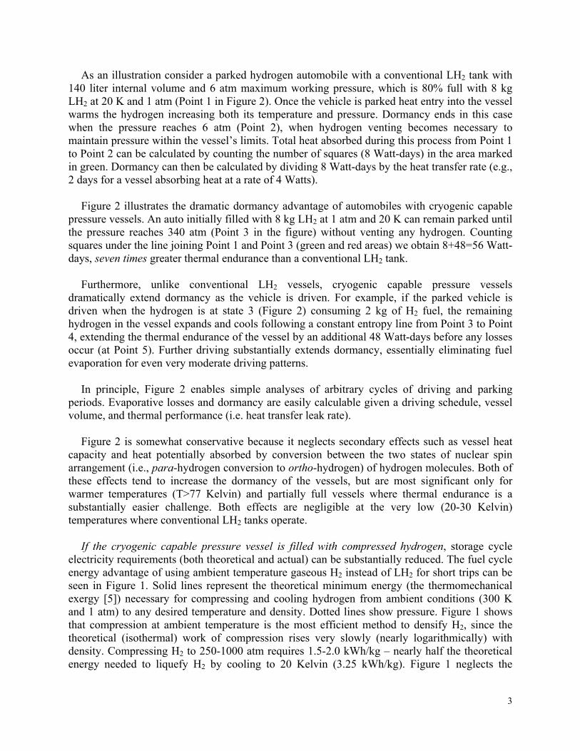
The dormancy (period of inactivity before a vessel releases hydrogen to reduce pressure build
up) is an important parameter for LH2 vehicle acceptability. Dormancy can be calculated from the first law of thermodynamics [4] and the properties of H2 [5]. We have generated a diagram of hydrogen thermodynamic properties (Figure 2) to simplify visualization and graphical calculation of dormancy for hydrogen vessels.
This diagram uses axes of internal energy and density instead of more traditional temperature
and pressure. A dormancy calculation begins by identifying the initial thermodynamic state in Figure 2 (density and internal energy) of the hydrogen contained in the vessel. From this initial point (e.g., point 1), the thermodynamic state of hydrogen fuel onboard a parked vehicle moves horizontally to the right (warming at constant density) as heat enters from the environment, until the hydrogen pressure reaches the vessel maximum and some hydrogen needs to be used or vented. The cumulative thermal energy absorbed while a car is parked can be calculated by multiplying the amount of hydrogen in the vessel by the total change in its specific internal energy. This total thermal energy is shown as the area in Figure 2 under the horizontal line joining the initial and final points in the process (neglecting temperature stratification, vessel thermal capacity and para-ortho conversion). Dormancy is then equal to the total heat absorbed (the area under the line) divided by the heat entry rate.
An appropriate choice of scales in Figure 2 radically simplifies dormancy calculations. The
grid scale in the internal energy (horizontal) axis is set at 86.4 kJ/kg H2, which converts to 1 Watt-day/kg H2 (1 day=86,400 seconds). The grid scale in the vertical axis represents 1 kg H2. Therefore, the area of a grid square represents 1 Watt-day of heating. The total change in internal energy (in Watt-days) can be easily calculated by counting the squares under the horizontal line representing the parking process. Dormancy is calculated by dividing the internal energy change (in Watt-days) by the rate of heat transfer (in Watts).
3
As an illustration consider a parked hydrogen automobile with a conventional LH2 tank with 140 liter internal volume and 6 atm maximum working pressure, which is 80% full with 8 kg LH2 at 20 K and 1 atm (Point 1 in Figure 2). Once the vehicle is parked heat entry into the vessel warms the hydrogen increasing both its temperature and pressure. Dormancy ends in this case when the pressure reaches 6 atm (Point 2), when hydrogen venting becomes necessary to maintain pressure within the vessel’s limits. Total heat absorbed during this process from Point 1 to Point 2 can be calculated by counting the number of squares (8 Watt-days) in the area marked in green. Dormancy can then be calculated by dividing 8 Watt-days by the heat transfer rate (e.g., 2 days for a vessel absorbing heat at a rate of 4 Watts).
Figure 2 illustrates the dramatic dormancy advantage of automobiles with cryogenic capable
pressure vessels. An auto initially filled with 8 kg LH2 at 1 atm and 20 K can remain parked until the pressure reaches 340 atm (Point 3 in the figure) without venting any hydrogen. Counting squares under the line joining Point 1 and Point 3 (green and red areas) we obtain 8+48=56 Watt-days, seven times greater thermal endurance than a conventional LH2 tank.
Furthermore, unlike conventional LH2 vessels, cryogenic capable pressure vessels
dramatically extend dormancy as the vehicle is driven. For example, if the parked vehicle is driven when the hydrogen is at state 3 (Figure 2) consuming 2 kg of H2 fuel, the remaining hydrogen in the vessel expands and cools following a constant entropy line from Point 3 to Point 4, extending the thermal endurance of the vessel by an additional 48 Watt-days before any losses occur (at Point 5). Further driving substantially extends dormancy, essentially eliminating fuel evaporation for even very moderate driving patterns.
In principle, Figure 2 enables simple analyses of arbitrary cycles of driving and parking
periods. Evaporative losses and dormancy are easily calculable given a driving schedule, vessel volume, and thermal performance (i.e. heat transfer leak rate).
Figure 2 is somewhat conservative because it neglects secondary effects such as vessel heat
capacity and heat potentially absorbed by conversion between the two states of nuclear spin arrangement (i.e., para-hydrogen conversion to ortho-hydrogen) of hydrogen molecules. Both of these effects tend to increase the dormancy of the vessels, but are most significant only for warmer temperatures (T>77 Kelvin) and partially full vessels where thermal endurance is a substantially easier challenge. Both effects are negligible at the very low (20-30 Kelvin) temperatures where conventional LH2 tanks operate.
If the cryogenic capable pressure vessel is filled with compressed hydrogen, storage cycle
electricity requirements (both theoretical and actual) can be substantially reduced. The fuel cycle energy advantage of using ambient temperature gaseous H2 instead of LH2 for short trips can be seen in Figure 1. Solid lines represent the theoretical minimum energy (the thermomechanical exergy [5]) necessary for compressing and cooling hydrogen from ambient conditions (300 K and 1 atm) to any desired temperature and density. Dotted lines show pressure. Figure 1 shows that compression at ambient temperature is the most efficient method to densify H2, since the theoretical (isothermal) work of compression rises very slowly (nearly logarithmically) with density. Compressing H2 to 250-1000 atm requires 1.5-2.0 kWh/kg – nearly half the theoretical energy needed to liquefy H2 by cooling to 20 Kelvin (3.25 kWh/kg). Figure 1 neglects the

4
additional exergy (0.75 kWh/kg) needed to convert LH2 to 95-100% parahydrogen. Typical actual energy requirements to compress and/or liquefy hydrogen are double or triple theoretical minimums [6, 7]. Electrolysis can generate high pressure H2 at near theoretical minimum compression work [8].
An upper bound on energy savings due to ambient temperature refueling can be estimated by
assuming use of compressed H2 for all trips under 200 km, accounting for 85% or more of vehicle distance traveled [9]. A hydrogen automobile consuming 150 kg/yr of compressed H2 and electricity savings of ~8 kWhe/kg H2 (relative to LH2) could use 1200 kWh/yr less electricity than an automobile fueled exclusively with LH2.
Finally, cryogenic capable pressure vessels offer a number of potential safety advantages. The
most dramatic and perhaps counterintuitive is the radically lower theoretical burst energy of low temperature H2. Figure 3 shows the theoretical maximum mechanical energy released by a sudden adiabatic expansion (e.g. in a vessel rupture) of high pressure hydrogen gas from three temperatures (80 K, 150 K and 300 K). H2 stored at 70 atm and 300 K will release a maximum mechanical energy of 0.55 kWh/kg H2 if suddenly (i.e. adiabatically) expanded to atmospheric pressure (cooling substantially). Counterintuitively, this maximum energy release increases only slightly with much higher H2 pressures. Raising vessel pressure to 1000 atm (1400% increase from 70 atm) increases maximum mechanical energy release by only 10%, while shrinking vessel volume and strengthening (thickening) vessel walls many times over. The low burst energy and high hydrogen storage density of cryogenic temperatures combine synergistically, permitting smaller vessels which can be better packaged onboard to withstand automobile collisions. The vacuum jacket surrounding a cryogenic pressure vessel (Figure 4) offers a second layer of protection, eliminating environmental impacts over the life of the pressure vessel. Vacuum jacketing also provides expansion volume to mitigate shocks from hydrogen release. Finally, cryogenic vessels avoid the fast fill heating and overpressures (up to 25%) typical of ambient temperature vessels, consequently operating at higher safety factors, especially as driving the automobile cools the remaining hydrogen fuel and reduces average hydrogen pressures further over typical driving and refueling cycles.
3. Technology Validation
Two generations of cryogenic capable pressure vessels incorporating aluminum-lined,
composite-wrapped vessels, an outer vacuum vessel, and multi-layer vacuum insulation to minimize heat transfer (Figure 4), have been designed, assembled, and installed at LLNL. The designs also included instrumentation for pressure and temperature as well as safety devices to prevent vessel rupture.
The generation 1 prototype operates at a maximum pressure of 245 atm. with a 135 liter
internal volume and 9.6 kg LH2 capacity. Six vessels of this design were built, with five used for DOT, ISO and SAE certification tests. The vessels successfully met all test criteria [10]. The sixth vessel was installed into a 1992 Ford Ranger pickup truck powered by a hydrogen internal combustion engine (Figure 5). Integration of the cryogenic capable pressure vessel required multiple changes to the vehicle fueling system to accommodate both cryogenic LH2 and ambient H2 gas. The Ford Ranger underwent initial shakedown testing at Lawrence Livermore National

5
Laboratory and demonstrated refueling on both LH2 and GH2 validating operation on both at SunLine Transit (Thousand Palms, California).
Following this proof of concept an improved generation 2 prototype vessel (Figure 4) was
developed. The generation 2 cryogenic capable pressure vessel is stronger (340 atm.) with a greater internal volume (151 liter) storing more fuel (10.7 kg LH2) than the previous generation in a total package that is considerably more compact and easily stored (horizontal). After satisfactory pressure, cryogenic and vacuum testing, the vessel was installed in an experimental Toyota Prius hydrogen hybrid vehicle (Figure 6). Vessel trunk location is not optimal and future work will aim at improved packaging that better permits luggage storage.
This hydrogen hybrid Prius was then test driven 1,050 km on a single tank of LH2 — the
longest for a hydrogen vehicle [11]. The drive was conducted on-site at LLNL so traffic and speeds were atypical. Under typical driving we would expect ~800 km driving range based on the EPA fuel economy rating for the Prius and the capacity of the storage tank.
In subsequent thermal endurance testing, the cryogenic capable pressure vessel onboard the
hydrogen hybrid Prius was fueled with 10 kg LH2 (93% full) and then parked as temperature and pressure rise due to heat entering from the environment were measured. Leakage through a valve prematurely ended the experiment after 6 days [12]. Nevertheless the experiment demonstrated the longest known dormancy for an automotive LH2 vessel. Thermodynamic analysis of the pressure and temperature data, along with heat capacity for aluminum, carbon composite, and hydrogen [4], enabled calculation of heat transfer rate into the vessel. Heat transfer of 3-4 Watts was estimated, sufficient for ~2 weeks of evaporation-free LH2 hold time.
Detailed component weight and volume breakdowns for the generation 1 and 2 prototype
cryogenic capable pressure vessels and storage system balance of plant are given in Table 1. This table shows that the generation 2 prototype increases hydrogen storage capacity (to 10.7 kg LH2) in a pressure vessel of weight and external volume comparable to the first, but packaged in a smaller and substantially lighter vacuum jacket and storage system accessories. This generation 2 storage system weighs 187 kg and occupies 323 liters. This storage performance meets the 2007 weight target and approaches the 2007 volume target of the U.S. Department of Energy (DOE) Hydrogen Program [13]. Even more ambitious weight and volume targets have been proposed for 2010 and 2015. Achieving these goals with cryogenic capable vessels require substantial further improvements.
4. Ongoing and Future Work
Cryogenic vessels often demand thick insulation (~3 cm) for adequate thermal performance,
negatively impacting volumetric hydrogen storage capacity. Thermodynamic analysis (Figure 2 and [2]) indicates that cryogenic capable pressure vessels are approximately an order of magnitude less sensitive to heat transfer than conventional low pressure cryogenic systems, thus enabling thin thermal insulation (~1 cm) and much improved storage density. Starting with the generation 2 design and reducing thermal insulation thickness from ~3 cm to ~1.5 cm leads to a generation 3 design that is 23% more compact (225 liters vs. 297 liters; Table 1), meeting the

6
very challenging DOE 2010 weight and volume targets. Ultra-thin insulation may suffice for controlling heat entry at ~7 Watts through careful vessel support and insulation design, maintaining ~5 days dormancy for a full tank and avoiding evaporative losses under typical utilization scenarios (few vehicle owners fill the tank and then immediately park for multiple days). Dormancy will increase rapidly as the vehicle is driven and the fill level drops.
The US Department of Energy has also established cost targets for hydrogen storage systems [13]. While cryogenic pressure vessels are projected to be cost competitive with respect to alternatives, they still cost 3-4 times more than the DOE 2010 target ($13.6/kWh vs. $4/kWh) [15]. Cost may therefore be the most challenging of DOE targets, even though future improvements may reduce the cost of cryogenic pressure vessels. 5. Conclusions
Unlike other fuels, hydrogen can be produced and consumed without generating carbon dioxide. If generated using renewable energy, hydrogen becomes a versatile, storable, and universal carbonless energy carrier that does not pollute. The greatest engineering challenge associated with hydrogen fuel is storing enough hydrogen onboard the vehicle for a reasonable range (500 km).
Cryogenic capable pressure vessels can store high-density hydrogen, similar to liquid hydrogen vessels, without the evaporative losses. They are more compact than compressed hydrogen, therefore reducing need for expensive carbon fiber. They are light and capable of fast refueling, offering a choice of refueling with either liquid hydrogen for long trips or compressed hydrogen gas for shorter trips.
The versatility and flexibility of cryogenic capable pressure vessels enables long-range vehicles that avoid evaporative losses, maintain reasonable cost, and allow fast refueling. The concept has been demonstrated on a hydrogen hybrid vehicle that maximized driving range on a single fuel tank while maintaining reasonable thermal endurance. A new pressure vessel design promises to meet the very challenging Department of Energy hydrogen storage 2010 weight and volume targets. Acknowledgments This project was funded by DOE, Office of Hydrogen and Fuel Cell Technologies, Monterey Gardiner, Technology Development Manager. This work performed under the auspices of the U.S. Department of Energy by Lawrence Livermore National Laboratory under Contract DE-AC52-07NA27344. References 1. Aceves, S.M., Berry, G.D., and Rambach, G.D., “Insulated Pressure Vessels for Hydrogen
Storage on Vehicles,” International Journal of Hydrogen Energy, Vol. 23, No. 7, pp. 583-591, 1998.
2. Aceves, S.M., Berry, G.D., “Thermodynamics of Insulated Pressure Vessels for Vehicular

7
Hydrogen Storage,” ASME Journal of Energy Resources Technology, Vol. 120, No. 2, pp. 137-142, 1998.
3. Aceves, S.M., Berry, G.D., Martinez-Frias, J., and Espinosa-Loza, F., “Vehicular Storage of Hydrogen in Insulated Pressure Vessels,” International Journal of Hydrogen Energy, Volume 31, pp. 2274-2283, 2006.
4. McCarty, R.D., “Hydrogen: Its Technology and Implications, Hydrogen Properties, Volume III,” CRC Press, Cleveland, OH. 1975.
5. Moran, M.J., “Availability Analysis: A Guide to Efficient Energy Use,” Prentice-Hall, Inc., Englewood Cliffs, New Jersey, 1982.
6. Peschka, W., “Liquid Hydrogen, Fuel of the Future,” Springer-Verlag, New York, NY. 1992. 7. Bracha, M., Lorenz, G., Patzelt, A., Wanner, M., “Large-Scale Hydrogen Liquefaction in
Germany,” International Journal of Hydrogen Energy, Vol. 19, No. 1, pp. 53-59, 1994. 8. Fickett A.P., Kalhammer F.R., “Water electrolysis,” In: Cox, KE, Williamson KD editors.
“Hydrogen: its technology and implications, Vol. 1, Production technologies,” CRC Press, Cleveland, OH, p. 3–41, 1977.
9. Klinger, D., Kuzmyak JR., “Personal Travel in the United States,” Vol. 1, 1983-1984, Nationwide Personal Transportation Study, Report PB89-235378, prepared for the US Department of Transportation, Office of Highway Information Management, Washington, DC., 1984.
10. Aceves, S.M., Martinez-Frias, J., Espinosa-Loza, F., “Performance Evaluation Tests of Insulated Pressure Vessels for Vehicular Hydrogen Storage,” Proceedings of the World Hydrogen Energy Conference, Montreal, Canada, June 2002.
11. Aceves, S.M., “Setting a World Driving Record with Hydrogen,” Science and Technology Review, June 2007, pp. 11-16.
12. Aceves, S.M., Berry, G.D., Espinosa-Loza, F., Ledesma-Orozco, E., Ross, T., Switzer, V., Weisberg, A., “Automotive Cryogenic Capable Pressure Vessels for Compact, High Dormancy (L)H2 Storage,” Proceedings of the DOE Hydrogen and Fuel Cell Annual Merit Review, Crystal City, Virginia, 2008, http://www.hydrogen.energy.gov/pdfs/progress08/vii_6_aceves.pdf.
13. Department of Energy, Office of Energy Efficiency and Renewable Energy Hydrogen, Fuel Cells & Infrastructure Technologies Program Multi-Year Research, Development and Demonstration Plan, http://www.eere.energy.gov/hydrogenandfuelcells/mypp
14. Ahluwalia, R.K., and Peng, J.K., “Dynamics of cryogenic hydrogen storage in insulated pressure vessels for automotive applications,” International journal of hydrogen energy, Vol. 33, pp. 4622–4633, 2008.
15. Lasher, S., McKenney, K., Sinha, J., Rosenfeld, J., “Analyses of Hydrogen Storage Materials and On-Board Systems,” Proceedings of the DOE Hydrogen and Fuel Cell Annual Merit Review, Crystal City, Virginia, 2008, http://www.hydrogen.energy.gov/pdfs/progress08/iv_e_1_lasher.pdf

8
Table 1. Weight and volume for the main system components for the three generations of cryogenic capable pressure vessels. Generations 1 and 2 have been built and respectively installed in a Ford Ranger Pickup Truck and in a Toyota Prius. Generation 3 is currently being built. For comparison, the DOE 2010 targets are 6% weight fraction and 45 g H2/L. DOE 2015 targets are 9% weight fraction and 81 g H2/L [13]. Storage calculations assume 70.7 kg/m3 hydrogen density (LH2 at 20 K and 1 atm). The table assumes that all stored hydrogen is usable, although driving at high power for long time may drop the vessel pressure below the necessary level to run the engine or fuel cell, reducing the net hydrogen storage density by a few percent [14]. An in-tank heat exchanger (generation 3) may minimize this effect. Generation 1 Generation 2 Generation 3 Components Weight,
kg Volume
L Weight,
kg Volume
L Weight,
kg Volume
L Hydrogen capacity (LH2) 9.6 135 10.7 151 10.7 151 Pressure vessel(s) 65 33 68 34 61 28 Insulation and vacuum shell 117 212 69 111 51 45 Mounting brackets 9.1 1.3 7 1 6 1 In-tank heat exchanger 0 0 0 0 0.3 0.04 Total, vessel and vacuum shell
201 381 155 297 129 225
Computer 4.6 3 0.2 0.5 0.2 0.5 Electronic boards 23.9 52 2.2 5 2.2 5 Valves and valve box 27.3 5.44 19.9 15.8 6.9 0.78 Pressure transmitter, gauge, regulator, rupture discs
4.2 0.83 1.1 0.6 1.1 0.6
Heat exchanger 6.8 5 1.5 1.8 1.5 1.8 Miscellaneous tubing, fittings, etc.
73.9 45.9 7 2.0 4 1.5
Total for accessories 141 112 32 26 16 10 Total 341 493 187 323 145 235 H2 weight fraction 2.80% 5.73% 7.38% Volume performance, g/L 19.39 33.16 45.49

9
Figure 1. Commercial automotive hydrogen storage technologies occupy the extremes of this phase diagram. Hydrogen is often stored as a compressed gas (red dot) at ambient temperature (horizontal axis), very high pressure (dotted lines), and relatively low density (vertical axis). Hydrogen is much more compact as a cryogenic liquid (blue dot) but with higher energetic cost (solid lines indicate the theoretical minimum work, also known as thermomechanical exergy) to compress and/or liquefy hydrogen. Cryogenic capable pressure vessels have flexibility to operate across a broad region (shaded in green) of the phase diagram, and therefore can be fueled with gaseous H2 at a low energetic cost when energy or fuel cost savings is important or with LH2 when long driving range, or low-pressure operation is desired.

10
Figure 2. Phase diagram for hydrogen showing density (right vertical axis) and internal energy (upper horizontal axis), with lines for constant pressure (green), temperature (blue) and entropy (red). The figure also shows a thick saturation line that separates the vapor phase (right) from the two-phase liquid-vapor region (left). A second vertical axis in the left shows the mass of hydrogen contained in a vessel with 140-liter internal volume, which would store 10 kg of LH2 at 20 K and 1 bar. The figure also shows points and areas representing dormancy (in Watt-days) of conventional LH2 tanks (green area) and cryogenic capable pressure vessels (green+red+blue areas).

11
Figure 3. Maximum mechanical energy (per kilogram of hydrogen) released upon instantaneous expansion of H2 gas (e.g. from a pressure vessel) as a function of initial storage pressure at 80 K, 150 K, and 300 K. For comparison, note that the chemical energy content of hydrogen is 33.3 kWh/kg. This mechanical energy is the theoretical maximum available work based on reversible adiabatic expansion from the pressure shown to 1 atm, calculated from internal energy differences of H2 gas before and after isentropic expansion.

12
Figure 4. Generation 2 cryogenic capable pressure vessel design. Inner vessel is an aluminum-lined, carbon fiber-wrapped pressure vessel typically used for storage of compressed gases. This vessel is surrounded by a vacuum space filled with numerous sheets of highly reflective metalized plastic (minimizing heat transfer into vessel), and an outer jacket of stainless steel. The outer tank measures 129 cm long with an outer diameter of 58 cm.

13
Figure 5. Generation 1 cryogenic capable pressure vessel (245 atm, 135 liter, 9 kg LH2) installed on a hydrogen fueled 1992 Ford Ranger truck.

14
Figure 6. Generation 2 cryogenic capable pressure vessel design with 151 L internal volume installed onboard a hydrogen fueled Toyota Prius.