High-definition Vandal-proof Dome Camera - Hikvision...
53
High-definition Vandal-proof Dome Camera·User Manual High-definition Vandal-proof Dome Camera User Manual UD.6L0201D0076A01
Transcript of High-definition Vandal-proof Dome Camera - Hikvision...
High-definition Vandal-proof Dome Camera·User Manual
0
0
High-definition Vandal-proof
Dome Camera
User Manual
UD.6L0201D0076A01
High-definition Vandal-proof Dome Camera·User Manual
1
1
Thank you for purchasing our product. If there are any questions,
or requests, please do not hesitate to contact the dealer.
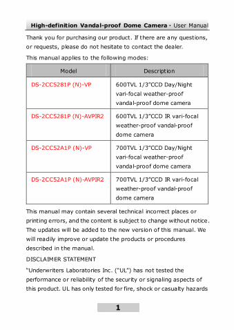
This manual applies to the following modes:
Model Description
DS-2CC5281P (N)-VP 600TVL 1/3”CCD Day/Night
vari-focal weather-proof
vandal-proof dome camera
DS-2CC5281P (N)-AVPIR2 600TVL 1/3”CCD IR vari-focal
weather-proof vandal-proof
dome camera
DS-2CC52A1P (N)-VP 700TVL 1/3”CCD Day/Night
vari-focal weather-proof
vandal-proof dome camera
DS-2CC52A1P (N)-AVPIR2 700TVL 1/3”CCD IR vari-focal
weather-proof vandal-proof
dome camera
This manual may contain several technical incorrect places or
printing errors, and the content is subject to change without notice.
The updates will be added to the new version of this manual. We
will readily improve or update the products or procedures
described in the manual.
DISCLAIMER STATEMENT
“Underwriters Laboratories Inc. (“UL”) has not tested the
performance or reliability of the security or signaling aspects of
this product. UL has only tested for fire, shock or casualty hazards
High-definition Vandal-proof Dome Camera·User Manual
2
2
as outlined in UL’s Standard(s) for Safety, UL60950-1. UL
Certification does not cover the performance or reliability of the
security or signaling aspects of this product. UL MAKES NO
REPRESENTATIONS, WARRANTIES OR CERTIFICATIONS
WHATSOEVER REGARDING THE PERFORMANCE OR RELIABILITY
OF ANY SECURITY OR SIGNALING RELATED FUNCTIONS OF THIS
PRODUCT.”
0100001021109
High-definition Vandal-proof Dome Camera·User Manual
3
3
Regulatory Information
FCC Information
FCC compliance: This equipment has been tested and found to
comply with the limits for a digital device, pursuant to part 15 of
the FCC Rules. These limits are designed to provide reasonable
protection against harmful interference when the equipment is
operated in a commercial environment. This equipment generates,
uses, and can radiate radio frequency energy and, if not installed
and used in accordance with the instruction manual, may cause
harmful interference to radio communications. Operation of this
equipment in a residential area is likely to cause harmful
interference in which case the user will be required to correct the
interference at his own expense.
FCC Conditions
This device complies with part 15 of the FCC Rules. Operation is
subject to the following two conditions:
1. This device may not cause harmful interference. 2. This device must accept any interference received, including
interference that may cause undesired operation.
EU Conformity Statement
This product and - if applicable - the supplied
accessories too are marked with "CE" and comply
therefore with the applicable harmonized
European standards listed under the Low Voltage Directive
2006/95/EC, the EMC Directive 2004/108/EC.
High-definition Vandal-proof Dome Camera·User Manual
4
4
2002/96/EC (WEEE directive): Products marked
with this symbol cannot be disposed of as unsorted
municipal waste in the European Union. For proper
recycling, return this product to your local supplier
upon the purchase of equivalent new equipment, or dispose of it at
designated collection points. For more information see:
www.recyclethis.info. 2006/66/EC (battery directive): This product
contains a battery that cannot be disposed of as
unsorted municipal waste in the European Union.
See the product documentation for specific battery
information. The battery is marked with this
symbol, which may include lettering to indicate cadmium (Cd),
lead (Pb), or mercury (Hg). For proper recycling, return the battery
to your supplier or to a designated collection point. For more
information see: www.recyclethis.info.
High-definition Vandal-proof Dome Camera·User Manual
5
5
Table of Contents
1 Introduction ........................................................................7 1.1 Product Features ...................................................... 7 1.2 Overview ................................................................. 8
2 Installation..........................................................................9 2.1 Ceiling Mounting ...................................................... 9 2.2 Ceiling Mounting with a gang box ........................... 13 2.3 Wall Mounting ........................................................ 17 2.4 Side Conduit Cabling .............................................. 20 2.5 Wiring .................................................................... 21
3 Menu Operations...............................................................23 3.1 Menu Description ................................................... 23 3.2 Lens Settings ......................................................... 24 3.3 Shutter/AGC Setting .............................................. 25 3.4 White Balance Setting ............................................ 28 3.5 Backlight Setting .................................................... 30 3.6 Picture Adjust Setting............................................. 31 3.7 ATR Setting ............................................................ 32 3.8 Motion Detection Setting ........................................ 33 3.9 Privacy Mask Setting .............................................. 35 3.10 Day/Night Setting ................................................ 36 3.11 NR Setting ........................................................... 39 3.12 Camera ID Setting ............................................... 40 3.13 SYNC Setting ....................................................... 41 3.14 Language Setting ................................................. 42 3.15 Camera Reset Setting........................................... 42 3.16 Defective Pixel Correct Settings ............................ 42 3.17 Save All/Exit ........................................................ 43
High-definition Vandal-proof Dome Camera·User Manual
6
6
Glossary ................................................................................44 Troubleshooting ...................................................................48 Technical Maintenance ........................................................50
High-definition Vandal-proof Dome Camera·User Manual
7
7
1 Introduction
1.1 Product Features
This series of camera adopts high-sensitive sensor and advanced
circuit board design technology. It possesses of high resolution,
low distortion, and low noise features, etc. It is extremely suitable
for surveillance system and image process system.
The main features are as fo llows:
Adopt high-performance SONY CCD, up to 700TVL
resolution, providing high definition and clear image
OSD menu, which enables user to configure the detailed
parameters
Support Digital Wide Dynamic Range (D-WDR) for
backlighting surveillance
Auto-white balance with high color rendition
High Signal Noise Ratio (SNR), which brings clear and
high-quality image
Auto electronic shutter control to adapt to the different
surveillance environments
Auto gain control, adaptive brightness
Auto-iris
Support up to 8 configurable privacy masks to ensure your
privacy

High-definition Vandal-proof Dome Camera·User Manual
8
8
Advanced 3-axis design allows this dome camera to be
adjusted 0-355° horizontally and 0-75° vertically to meet
different mounting requirements
1.2 Overview
1 34
56
7
2
8
Figure 1-1 Overview
1 Black Liner 5 Power Cable
2 Lower Dome 6 Video Cable
3 AUX Interface 7 Lens
4 Menu Button 8 Adapter Ring
High-definition Vandal-proof Dome Camera·User Manual
9
9
2 Installation
Before you start:
Please make sure that the device in the package is in good
condition and all the assembly parts are included.
This series of camera support ceiling mounting, ceiling mounting
with a gang box, wall mounting and side conduit mounting.
2.1 Ceiling Mounting
Note:
Please make sure that the ceiling is strong enough to withstand
three times the weight of the camera.
Steps:
1. Attach the drill template (supplied) to the place where you
want to fix the camera.
2. Drill 3 screw holes and one cable hole (if you want to route the
cable through the mounting base) according to the drill
template.
High-definition Vandal-proof Dome Camera·User Manual
10
10
Cable Outlet
Screw Hole Screw Hole
Screw Hole
Drilling Template for Outdoor
Day/Night Vandal-proof Dome Camera
Side Cable Outlet
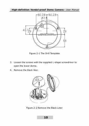
Figure 2-1 The Drill Template
3. Loosen the screws with the supplied L-shape screwdriver to
open the lower dome.
4. Remove the black liner.
Figure 2-2 Remove the Black Liner
High-definition Vandal-proof Dome Camera·User Manual
11
11
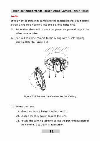
Note:
If you want to install the camera to the cement ceiling, you need to
screw 3 expansion screws into the 3 drilled holes first.
5. Route the cables and connect the power supply and output the
video on a monitor.
6. Secure the dome camera to the ceiling with 3 self-tapping
screws. Refer to Figure 2-3.
Figure 2-3 Secure the Camera to the Ceiling
7. Adjust the Lens.
1). View the camera image via the monitor.
2). Loosen the lock screw besides the lens
3). Rotate the panning table to adjust the panning position of
the camera. 0 to 355° is adjustable.
High-definition Vandal-proof Dome Camera·User Manual
12
12
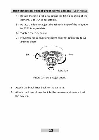
4). Rotate the tilting table to adjust the tilting position of the
camera. 0 to 75° is adjustable.
5). Rotate the lens to adjust the azimuth angle of the image. 0
to 355° is adjustable.
6). Tighten the lock screw.
7). Move the focus lever and zoom lever to adjust the focus
and the zoom.
Figure 2-4 Lens Adjustment
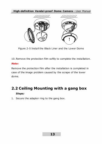
8. Attach the black liner back to the camera.
9. Attach the lower dome back to the camera and secure it with
the screws.
Tilt
Rotation
Pan
High-definition Vandal-proof Dome Camera·User Manual
13
13
Figure 2-5 Install the Black Liner and the Lower Dome
10. Remove the protection film softly to complete the installation.
Note:
Remove the protection film after the installation is completed in
case of the image problem caused by the scrape of the lower
dome.
2.2 Ceiling Mounting with a gang box
Steps:
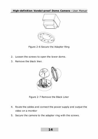
1. Secure the adapter ring to the gang box.
High-definition Vandal-proof Dome Camera·User Manual
14
14
Figure 2-6 Secure the Adapter Ring
2. Loosen the screws to open the lower dome.
3. Remove the black liner.
Figure 2-7 Remove the Black Liner
4. Route the cables and connect the power supply and output the
video on a monitor
5. Secure the camera to the adapter ring with the screws.

High-definition Vandal-proof Dome Camera·User Manual
15
15
Figure 2-8 Install the Camera
6. Adjust the lens.
1). View the camera image via the monitor.
2). Loosen the lock screw besides the lens
3). Rotate the panning table to adjust the panning position of
the camera. 0 to 355° is adjustable.
4). Rotate the tilting table to adjust the tilting position of the
camera. 0 to 75° is adjustable.
5). Rotate the lens to adjust the azimuth angle of the image. 0
to 355° is adjustable.
6). Tighten the lock screw.
7). Move the focus lever and zoom lever to adjust the focus
and the zoom.
7. Attach the black liner back to the camera.
High-definition Vandal-proof Dome Camera·User Manual
16
16
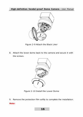
Figure 2-9 Attach the Black Liner
8. Attach the lower dome back to the camera and secure it with
the screws.
Figure 2-10 Install the Lower Dome
9. Remove the protection film softly to complete the installation.
Note:

High-definition Vandal-proof Dome Camera·User Manual
17
17
Remove the protection film after the installation is completed in
case of the image problem caused by the scrape of the lower
dome.
2.3 Wall Mounting
Note:
Please make sure that the wall is strong enough to withstand three
times the weight of the camera.
Steps:
1. Drill four expansion screw holes on the wall.
2. Secure the mount to the wall with the expansion screws.
3. Insert the adapter ring to the mount.
Figure 2-11 Install the Mount and the Adapter Ring
4. Loosen the screws to open the lower dome.
5. Remove the black liner.
6. Secure the camera to the adapter ring.
High-definition Vandal-proof Dome Camera·User Manual
18
18
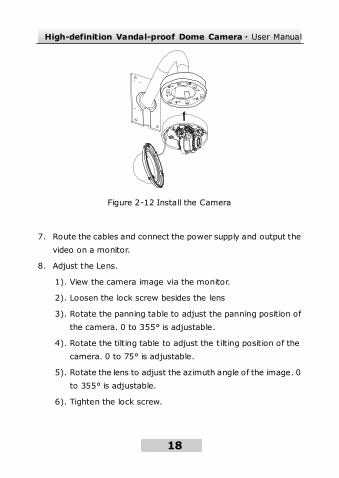
Figure 2-12 Install the Camera
7. Route the cables and connect the power supply and output the
video on a monitor.
8. Adjust the Lens.
1). View the camera image via the monitor.
2). Loosen the lock screw besides the lens
3). Rotate the panning table to adjust the panning position of
the camera. 0 to 355° is adjustable.
4). Rotate the tilting table to adjust the tilting position of the
camera. 0 to 75° is adjustable.
5). Rotate the lens to adjust the azimuth angle of the image. 0
to 355° is adjustable.
6). Tighten the lock screw.
High-definition Vandal-proof Dome Camera·User Manual
19
19
7). Move the focus lever and zoom lever to adjust the focus
and the zoom.
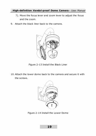
9. Attach the black liner back to the camera.
Figure 2-13 Install the Black Liner
10. Attach the lower dome back to the camera and secure it with
the screws.
Figure 2-14 Install the Lower Dome
High-definition Vandal-proof Dome Camera·User Manual
20
20
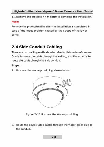
11. Remove the protection film softly to complete the installation.
Note:
Remove the protection film after the installation is completed in
case of the image problem caused by the scrape of the lower
dome.
2.4 Side Conduit Cabling
There are two cabling methods selectable for this series of camera.
One is to route the cable through the ceiling, and the other is to
route the cable though the side conduit.
Steps:
1. Unscrew the water-proof plug shown below.
Figure 2-15 Unscrew the Water-proof Plug
2. Route the power/video cables through the water-proof plug to
the conduit.
High-definition Vandal-proof Dome Camera·User Manual
21
21
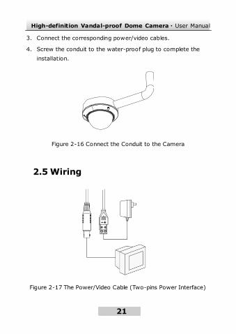
3. Connect the corresponding power/video cables.
4. Screw the conduit to the water-proof plug to complete the
installation.
Figure 2-16 Connect the Conduit to the Camera
2.5 Wiring
Figure 2-17 The Power/Video Cable (Two-pins Power Interface)
High-definition Vandal-proof Dome Camera·User Manual
22
22
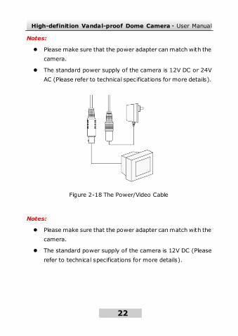
Notes:
Please make sure that the power adapter can match with the
camera.
The standard power supply of the camera is 12V DC or 24V
AC (Please refer to technical specifications for more details).
Figure 2-18 The Power/Video Cable
Notes:
Please make sure that the power adapter can match with the
camera.
The standard power supply of the camera is 12V DC (Please
refer to technical specifications for more details).
High-definition Vandal-proof Dome Camera·User Manual
23
23
3 Menu Operations
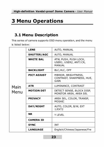
3.1 Menu Description
This series of camera supports OSD menu operation, and the menu
is listed below:
Main Menu
LENS AUTO, MANUAL
SHUTTER/AGC AUTO, MANUAL
WHITE BAL ATW, PUSH, PUSH LOCK, USER1, USER2, ANTI CR,
MANUAL
BACKLIGHT BLC,HLC, OFF
PICT ADJUST MIRROR, BRIGHTNESS, CONTRAST, SHARPNESS, HUE, GAIN
ATR LUMINANCE, CONTRAST
MOTION DET DETECT SENSE, BLOCK DISP, MONITOR AREA, AREA SEL
PRIVACY AREA SEL, COLOR, TRANSP, MOSAIC
DAY/NIGHT AUTO, COLOR, B/W, EXT 1/EXT2
NR Y LEVEL
CAMERA ID
SYNC INT
LANGUAGE English/Chinese/Japanese/Fre
High-definition Vandal-proof Dome Camera·User Manual
24
24
nch/Russian/ Portuguese/ Spanish/ German
CAMERA RESET
EXIT/SAVE ALL
3.2 Lens Settings
Move the cursor to LENS, and then set the menu button left/right
to select MANUAL or AUTO.
Selecting MANUAL mode, the iris is set at the maximum value,
and it is not configurable.
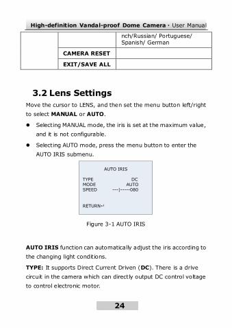
Selecting AUTO mode, press the menu button to enter the
AUTO IRIS submenu.
AUTO IRIS
TYPE DCMODE AUTO SPEED ---|-----080
RETURN
Figure 3-1 AUTO IRIS
AUTO IRIS function can automatically adjust the iris according to
the changing light conditions.
TYPE: It supports Direct Current Driven (DC). There is a drive
circuit in the camera which can directly output DC control voltage
to control electronic motor.
High-definition Vandal-proof Dome Camera·User Manual
25
25
MODE: AUTO, OPEN, and CLOSE are selectable for iris mode.
Selecting auto means the iris is adjusted automatically; selecting
open means the iris is fully open; and selecting close mean the iris
is totally closed.
SPEED: Adjust the iris speed. The higher the value is, the faster
the speed of the auto iris is. The value ranges from 0 to 255.
Note:
It is recommended that you adjust the iris speed only when the iris
vibrates.
3.3 Shutter/AGC Setting
SHUTTER/AGC allows you to adjust the way the system balances
SHUTTER and AGC settings in different light conditions. You can
set the different shutter and AGC value according to the luminance
level of the situation.
You can choose MANUAL or AUTO mode for the shutter and AGC.
Note:
On the lens setting interface, if you choose lens type as AUTO, the
AUTO IRIS can also be adjusted to change the brightness of the
image; otherwise only shutter and AGC are adjustable.
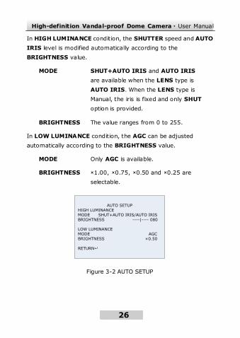
In the AUTO SETUP submenu (Figure 3-2), you can adjust the
BRIGHTNESS value. The system will automatically adjust the
SHUTTER, AGC and AUTO IRIS settings according to the
BRIGHTNESS value. And the system can define and recognize the
luminance level automatically.
High-definition Vandal-proof Dome Camera·User Manual
26
26
In HIGH LUMINANCE condition, the SHUTTER speed and AUTO
IRIS level is modified automatically according to the
BRIGHTNESS value.
MODE SHUT+AUTO IRIS and AUTO IRIS
are available when the LENS type is
AUTO IRIS. When the LENS type is
Manual, the iris is fixed and only SHUT
option is provided.
BRIGHTNESS The value ranges from 0 to 255.
In LOW LUMINANCE condition, the AGC can be adjusted
automatically according to the BRIGHTNESS value.
MODE Only AGC is available.
BRIGHTNESS ×1.00, ×0.75, ×0.50 and ×0.25 are
selectable.
AUTO SETUPHIGH LUMINANCEMODE SHUT+AUTO IRIS/AUTO IRISBRIGHTNESS ----|---- 080
LOW LUMINANCEMODE AGCBRIGHTNESS ×0.50
RETURN
Figure 3-2 AUTO SETUP
High-definition Vandal-proof Dome Camera·User Manual
27
27
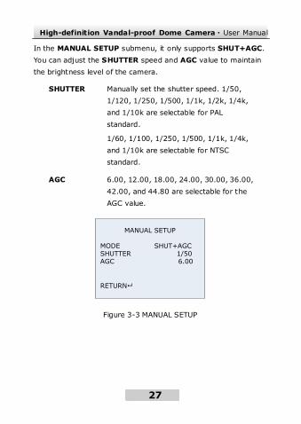
In the MANUAL SETUP submenu, it only supports SHUT+AGC.
You can adjust the SHUTTER speed and AGC value to maintain
the brightness level of the camera.
SHUTTER Manually set the shutter speed. 1/50,
1/120, 1/250, 1/500, 1/1k, 1/2k, 1/4k,
and 1/10k are selectable for PAL
standard.
1/60, 1/100, 1/250, 1/500, 1/1k, 1/4k,
and 1/10k are selectable for NTSC
standard.
AGC 6.00, 12.00, 18.00, 24.00, 30.00, 36.00,
42.00, and 44.80 are selectable for the
AGC value.
MANUAL SETUP
MODE SHUT+AGCSHUTTER 1/50AGC 6.00
RETURN
Figure 3-3 MANUAL SETUP
High-definition Vandal-proof Dome Camera·User Manual
28
28
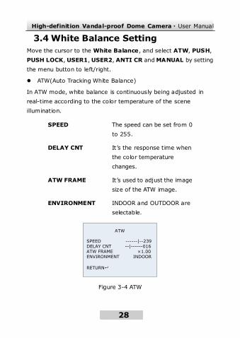
3.4 White Balance Setting
Move the cursor to the White Balance, and select ATW, PUSH,
PUSH LOCK, USER1, USER2, ANTI CR and MANUAL by setting
the menu button to left/right.
ATW(Auto Tracking White Balance)
In ATW mode, white balance is continuously being adjusted in
real-time according to the color temperature of the scene
illumination.
SPEED The speed can be set from 0
to 255.
DELAY CNT It’s the response time when
the color temperature
changes.
ATW FRAME It’s used to adjust the image
size of the ATW image.
ENVIRONMENT INDOOR and OUTDOOR are
selectable.
ATW
SPEED ------|--239DELAY CNT --|------016ATW FRAME ×1.00ENVIRONMENT INDOOR
RETURN
Figure 3-4 ATW
High-definition Vandal-proof Dome Camera·User Manual
29
29
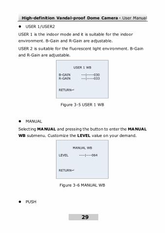
USER 1/USER2
USER 1 is the indoor mode and it is suitable for the indoor
environment. B-Gain and R-Gain are adjustable.
USER 2 is suitable for the fluorescent light environment. B-Gain
and R-Gain are adjustable.
USER 1 WB
B-GAIN ---|-----030 R-GAIN ---|-----033
RETURN
Figure 3-5 USER 1 WB
MANUAL
Selecting MANUAL and pressing the button to enter the MANUAL
WB submenu. Customize the LEVEL value on your demand.
MANUAL WB
LEVEL ----|----064
RETURN
Figure 3-6 MANUAL WB
PUSH
High-definition Vandal-proof Dome Camera·User Manual
30
30
In the PUSH mode, the viewed image retains color balance
automatically. The color in the image balances according to the
color temperature.
PUSH LOCK
In the PUSH LOCK mode, you can select a scene, and manually
adjust the white balance, and then lock the color temperature. It is
suitable for the environment which the color temperature slightly
changes.
ANTI CR (Anti Color Rolling)
In ANTI CR mode, the system suppresses the color rolling under
the fluorescent light environment.
3.5 Backlight Setting
Move the cursor to the BLC and select OFF, BLC or HLC by
pressing left/right button.
BLC (Backlight Compensation)
If there’s a strong backlight, the object in front of the backlight
appears silhouetted or dark. BLC can correct the exposure of the
subject. But the backlight environment is overexposed.
HLC(Highlight Compensation)
HLC masks strong light sources that usually flare across a scene.
This makes it possible to see the detail of the image that would
normally be hidden.
High-definition Vandal-proof Dome Camera·User Manual
31
31
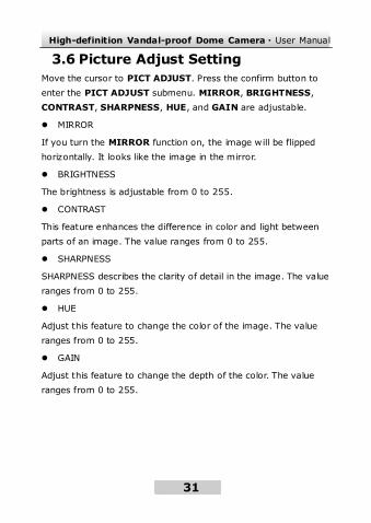
3.6 Picture Adjust Setting
Move the cursor to PICT ADJUST. Press the confirm button to
enter the PICT ADJUST submenu. MIRROR, BRIGHTNESS,
CONTRAST, SHARPNESS, HUE, and GAIN are adjustable.
MIRROR
If you turn the MIRROR function on, the image will be flipped
horizontally. It looks like the image in the mirror.
BRIGHTNESS
The brightness is adjustable from 0 to 255.
CONTRAST
This feature enhances the difference in color and light between
parts of an image. The value ranges from 0 to 255.
SHARPNESS
SHARPNESS describes the clarity of detail in the image. The value
ranges from 0 to 255.
HUE
Adjust this feature to change the color of the image. The value
ranges from 0 to 255.
GAIN
Adjust this feature to change the depth of the color. The value
ranges from 0 to 255.
High-definition Vandal-proof Dome Camera·User Manual
32
32
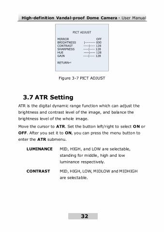
PICT ADJUST
MIRROR OFFBRIGHTNESS |-------- 000CONTRAST ----|---- 128SHARPNESS ----|---- 128HUE ----|---- 128GAIN ----|---- 128
RETURN
Figure 3-7 PICT ADJUST
3.7 ATR Setting
ATR is the digital dynamic range function which can adjust the
brightness and contrast level of the image, and balance the
brightness level of the whole image.
Move the cursor to ATR. Set the button left/right to select ON or
OFF. After you set it to ON, you can press the menu button to
enter the ATR submenu.
LUMINANCE MID, HIGH, and LOW are selectable,
standing for middle, high and low
luminance respectively.
CONTRAST MID, HIGH, LOW, MIDLOW and MIDHIGH
are selectable.
High-definition Vandal-proof Dome Camera·User Manual
33
33
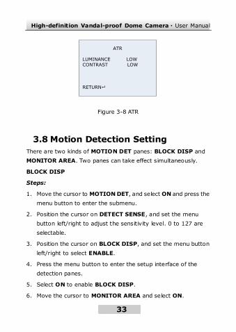
ATR
LUMINANCE LOWCONTRAST LOW
RETURN
Figure 3-8 ATR
3.8 Motion Detection Setting
There are two kinds of MOTION DET panes: BLOCK DISP and
MONITOR AREA. Two panes can take effect simultaneously.
BLOCK DISP
Steps:
1. Move the cursor to MOTION DET, and select ON and press the
menu button to enter the submenu.
2. Position the cursor on DETECT SENSE, and set the menu
button left/right to adjust the sensitivity level. 0 to 127 are
selectable.
3. Position the cursor on BLOCK DISP, and set the menu button
left/right to select ENABLE.
4. Press the menu button to enter the setup interface of the
detection panes.
5. Select ON to enable BLOCK DISP.
6. Move the cursor to MONITOR AREA and select ON.
High-definition Vandal-proof Dome Camera·User Manual
34
34
7. Return to the MAIN MENU and click SAVE ALL.
8. You can find the BLOCK DISP take effect after you exit the
main menu.
MONITOR AREA
Steps:
1. Move the cursor to MOTION DET, select ON and press the
menu button to enter the submenu.
2. Position the cursor on DETECT SENSE, and set the menu
button left/right to adjust the sensitivity level.
3. Position the cursor on MONITOR AREA. Select OFF to disable
area motion detection. Select ON to enable area motion
detection.
4. Position the cursor on AREA SEL to select one area. There are
four areas available.
5. Set the values of TOP, BOTTOM, LEFT and RIGHT. The size
and position of the area is defined by these values. And after
you set all this value, you can see a frame on the image.
6. Return to the MAIN MENU and click SAVE ALL.
7. You can find the MONITOR AREA frame take effect after you
exit the main menu.
Note:
The MONITOR AREA frame takes effect only when the BLOCK
DISP panes are included in the MONITOR AREA frame.
High-definition Vandal-proof Dome Camera·User Manual
35
35
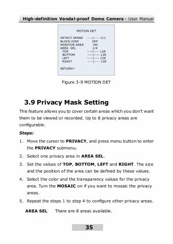
MOTION DET
DETECT SENSE ----|---- 111
BLOCK DISP OFF
MONITOR AREA ON AREA SEL 1/4 TOP ----|---- 128 BUTTOM ----|---- 128 LEFT ----|---- 128 RIGHT ----|---- 128
RETURN
Figure 3-9 MOTION DET
3.9 Privacy Mask Setting
This feature allows you to cover certain areas which you don’t want
them to be viewed or recorded. Up to 8 privacy areas are
configurable.
Steps:
1. Move the cursor to PRIVACY, and press menu button to enter
the PRIVACY submenu.
2. Select one privacy area in AREA SEL.
3. Set the values of TOP, BOTTOM, LEFT and RIGHT. The size
and the position of the area can be defined by these values.
4. Select the color and the transparency values for the privacy
area. Turn the MOSAIC on if you want to mosaic the privacy
areas.
5. Repeat the steps 1 to step 4 to configure other privacy areas.
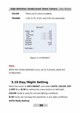
AREA SEL There are 8 areas available.
High-definition Vandal-proof Dome Camera·User Manual
36
36
COLOR There are 8 colors available.
TRANSP 1.00, 0.75, 0.50, and 0.00 are selectable.
PRIVACY AREA SEL 1/8 TOP ----|---- 128 BUTTOM ----|---- 128 LEFT ----|---- 128 RIGHT ----|---- 128COLOR 1TRANSP 0.00MOSAIC OFF
RETURN
Figure 3-10 PRIVACY
Note:
When the motion detection is on, up to 4 privacy areas are
configurable.
3.10 Day/Night Setting
Move the cursor to DAY/NIGHT, and select AUTO, COLOR, EXT
1/EXT 2 or B/W by setting the menu button to left/right.
COLOR mode is used for normal lighting conditions.
B/W mode can increase the sensitivity in low light conditions.
AUTO Mode Setting
High-definition Vandal-proof Dome Camera·User Manual
37
37
In AUTO mode, the day mode and the night mode can switch
automatically.
Steps:
1. After moving the cursor to DAY/NIGHT, set the menu button
left/right to select AUTO.
2. Press menu button to enter the submenu.
BURST Burst is an analog video, composite video
signal generated by a video-signal
generator used to keep the chrominance
subcarrier synchronized in a color
television signal. Select ON or OFF to
enable or disable the color burst function.
DELAYCNT The value ranges from 0 to 255. This value
is the delay time before the day/night
mode switches.
DAYNIGHT The value ranges from 0 to 255. The day
mode switches to the night mode when the
light condition reaches to the value you
select.
NIGHTDAY The value ranges from 0 to 255. The night
mode switches to the day mode when the
light condition reaches to the value you
select.
High-definition Vandal-proof Dome Camera·User Manual
38
38
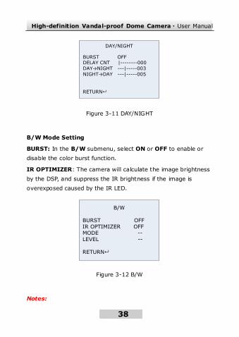
DAY/NIGHT
BURST OFF DELAY CNT |--------000
DAY→NIGHT ---|-----003
NIGHT→DAY ---|-----005
RETURN
Figure 3-11 DAY/NIGHT
B/W Mode Setting
BURST: In the B/W submenu, select ON or OFF to enable or
disable the color burst function.
IR OPTIMIZER: The camera will calculate the image brightness
by the DSP, and suppress the IR brightness if the image is
overexposed caused by the IR LED.
B/W
BURST OFFIR OPTIMIZER OFF MODE --LEVEL --
RETURN
Figure 3-12 B/W
Notes:
High-definition Vandal-proof Dome Camera·User Manual
39
39
There is no external triggered output for this series of dome
camera:
For the dome cameras which don’t support IR, the EXT 1/EXT
2 is not supported.
For the dome cameras which support IR, if you select EXT
1/EXT 2, the day mode switches to the night mode
automatically at the same time the IR LED turns on.
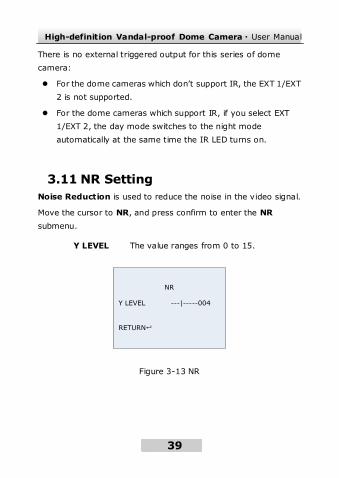
3.11 NR Setting
Noise Reduction is used to reduce the noise in the video signal.
Move the cursor to NR, and press confirm to enter the NR
submenu.
Y LEVEL The value ranges from 0 to 15.
NR
Y LEVEL ---|-----004
RETURN
Figure 3-13 NR
High-definition Vandal-proof Dome Camera·User Manual
40
40
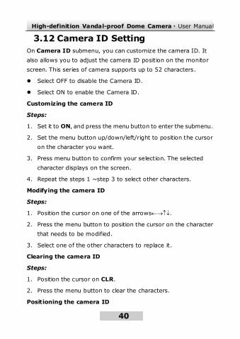
3.12 Camera ID Setting
On Camera ID submenu, you can customize the camera ID. It
also allows you to adjust the camera ID position on the monitor
screen. This series of camera supports up to 52 characters.
Select OFF to disable the Camera ID.
Select ON to enable the Camera ID.
Customizing the camera ID
Steps:
1. Set it to ON, and press the menu button to enter the submenu.
2. Set the menu button up/down/left/right to position the cursor
on the character you want.
3. Press menu button to confirm your selection. The selected
character displays on the screen.
4. Repeat the steps 1 ~step 3 to select other characters.
Modifying the camera ID
Steps:
1. Position the cursor on one of the arrows.
2. Press the menu button to position the cursor on the character
that needs to be modified.
3. Select one of the other characters to replace it.
Clearing the camera ID
Steps:
1. Position the cursor on CLR.
2. Press the menu button to clear the characters.
Positioning the camera ID
High-definition Vandal-proof Dome Camera·User Manual
41
41
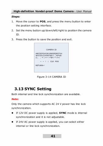
Steps:
1. Move the cursor to POS, and press the menu button to enter
the position setting interface.
2. Set the menu button up/down/left/right to position the camera
ID.
3. Press the button to save the position and exit.
CAMERA ID
ABCDEFGHIJKLMNOPQRSTUVWXYZ0123456789-!”#$%&’()_` , ¥:;<= >?@\^*.x+/
← → ↑ ↓ CLR POS
RETURN
Figure 3-14 CAMERA ID
3.13 SYNC Setting
Both internal and line lock synchronization are available.
Note:
Only the camera which supports AC 24 V power has line lock
synchronization.
If 12V DC power supply is applied, SYNC mode is internal
synchronization and it is not adjustable.
If 24V AC power supply is applied, you can select either
internal or line lock synchronization.
High-definition Vandal-proof Dome Camera·User Manual
42
42
Note:
Internal synchronization is the default SYNC method. Set the
menu button to right for about 2 seconds, you can switch the
SYNC mode to line-lock from the SYNC settings. Perform the
same operation to switch it to internal synchronization from
the line-lock.
3.14 Language Setting
This series of camera supports multi-language. English (default),
Chinese, Japanese, French, Russian, Portuguese, Spanish, and
German are selectable.
Steps:
1. Move the cursor to LANGUAGE.
2. Set the menu button left/right to select the language you need.
3.15 Camera Reset Setting
Move the cursor to CAMERA RESET, and press the menu button
to reset all camera settings to the default.
3.16 Defective Pixel Correct Settings
The CCD sensor of the lens may appear defective pixels. You can
trigger the defective pixel correction function to correct and
compensate the defective pixels.
Note:
High-definition Vandal-proof Dome Camera·User Manual
43
43
The defective pixel correct function may not be displayed on the
menu; you can enable the function by following the steps below.
Steps:
1. Exit the OSD menu to the live view screen.
1. Switch and hold the menu button to the left for 2 seconds until
you see the message of “COVER-UP LENS/CLOSE IRIS”.
2. Cover the lens or close the iris to prevent the light from
entering the lens.
3. Press the menu button to confirm. You will be able to see the
bright dot detects on the grainy screen.
4. After the process, the bright dot defects will disappear and you
can see “SUCCESS” on the screen.
5. Press the menu button to exit.
Note: An ERROR may occur because that the lens was not fully
covered. Please repeat above steps to try again.
3.17 Save All/Exit
Move the cursor to the Exit, and press the menu button to exit the
settings without saving.
Move the cursor to SAVE ALL, and press menu button to save the
settings and exit.
High-definition Vandal-proof Dome Camera·User Manual
44
44
Glossary
Note:
The glossary gives brief explanations to the basic operation
principle or the basic function of the camera. However, it doesn’t
mean the listed functions are all supported by this series of camera.
Please take the actual function in the corresponding specification
as the standard.
Definition:
Definition is the degree to distinguish the edge between two parts
clearly.
Contrast:
Contrast is the color difference between the brightest and darkest
parts.
Saturation:
Saturation is the degree of color purity. The color is purer, the
image is brighter.
DAY/NIGHT Auto Switch:
The cameras deliver color images during the day. And as light
diminishes at night, the cameras switch to night mode and deliver
black and white images with high quality.
AGC:
AGC is a control circuit that automatically changes the gain of a
receiver or other piece of equipment, so that the desired output
High-definition Vandal-proof Dome Camera·User Manual
45
45
signal remains essentially. When under low illumination, AGC will
regulate the gain and amplification of the video signal.
S/N ratio:
It is the ratio of Signal voltage and noise voltage. The ratio is larger,
the effect of noise is less, and the image is clearer.
White Balance:
White balance is the white rendition function of the camera to
adjust the color temperature according to the environment
automatically.
BLC:
If you focus on an object against strong backlight, the object will
be too dark to be seen clearly. The BLC (Backlight Compensation)
function can compensate light to the object in the front to make it
clear, but this causes the over-exposure of the background where
the light is strong.
SMART IR:
The SMART IR adopts the smart image processing technique to
automatically adjust the brightness curve by detecting multi-zone
brightness, and so as to prevent the over exposure of central point
existed in short IR distance conditions.
Motion Detection:
In the user-defined motion detection surveillance area, the moving
object can be detected and trigger alarm. The sensitive level can
be customized according to the environment.
Privacy Mask:
High-definition Vandal-proof Dome Camera·User Manual
46
46
This function allows you to block or mask certain area of a scene,
thus prevent the personal privacy from recording or live viewing.
OSD (On-Screen Display):
OSD is the texts superimposed on a screen. It can show the menu
on the screen.
Synchronous System:
Synchronization of the camera usually contains power
synchronization and internal synchronization. Internal
synchronization is realized by the synchronous signal which is
generated by the inside crystal oscillator.
ICR Auto Switch:
The filter will filter infrared light during the daytime and change to
normal filter at night to ensure a high sensitivity and clear image.
WDR (Wide Dynamic Range):
The wide dynamic range (WDR) function helps the camera provide
clear images even under back light circumstances. When there are
both very bright and very dark areas simultaneously in the field of
view, WDR balances the brightness level of the whole image and
provide clear images with details.
EIS (Electronic Image Stabilization):
Electronic image stabilization function can reduce certain ranges of
vibration which is caused by the external environment.
3D Digital Noise Reduction:
Comparing with the general 2D digital noise reduction, the 3D
digital noise reduction function processes the noise initiated by
High-definition Vandal-proof Dome Camera·User Manual
47
47
CCD besides processing the noise in the separated Y video signal
and C video signal.
HLC (High Light Compensation):
The HLC is capable of detecting and reversing the bright spots in
the picture (such as headlights) to black so as to achieve optimum
picture quality.
Digital Zoom:
Digital zoom helps to crop the entire image, and then digitally
enlarge the size of a portion of image that is needed to zoom in on.

High-definition Vandal-proof Dome Camera·User Manual
48
48
Troubleshooting
Problem 1:
Why does the camera restart intermittently? And the problem is
much more serious when infrared lights of IR camera are turned on
at night.
Possible Reasons:
The main and common reason is power supply shortage. This
problem may happen to the IR camera especially at night, because
the infrared lights are turned on at night and increase the power
consumption.
To Solve the Problem:
You need to ensure that the power supply matches with ±10% of
the nominal voltage. And the power consumption of power adapter
should meet the demand of the camera.
Problem 2:
The camera can never be focused by adjusting the focus-stick on
the lens. And there is also no use adjusting the back focus.
Possible Reasons:
The camera needs the lens with CS lens mount. When you install a
lens with C lens mount, the camera will never be focused.
To Solve the Problem:
You can change a lens with CS lens mount to the camera.
High-definition Vandal-proof Dome Camera·User Manual
49
49
Or you can use a C/CS adapter ring between the camera and the
lens with C lens mount.
Problem 3:
The camera is installed with an auto-iris lens. You adjust the focus
to get a clear image in the daytime, but the image is defocused at
night.
Possible Reasons:
In the daytime, the illumination is high, so the iris is adjusted to a
small size automatically. The DOF (depth of field) is long. But at
night, the iris is adjusted to a large size automatically, so the DOF
is shortened. The focus you adjusted in the daytime now locates
out of the DOF, so the image is defocused at night.
To Solve the Problem:
When you adjust the focus for a camera with an auto-iris lens, you
need to set the lens type to AES (auto electronic shutter) mode.
Under AES mode, the iris is adjusted to the largest size
automatically. Then you can adjust the focus to get a clear image.
At last, you need to set the lens type back to AI (auto iris) mode.
Or you can adjust the focus in low illumination condition, such as at
night.
Problem 4:
A camera with OSD menu and an auto-iris lens displays black video,
but the OSD menu can be called and displayed.
Possible Reasons:
High-definition Vandal-proof Dome Camera·User Manual
50
50
Auto-iris lens connector is loose contact.
Or the iris driven mode of the camera does not match with the
mode of auto-iris lens.
To Solve the Problem:
Check the auto-iris lens connector to ensure good contact.
Set the iris driven mode of the camera the same as the mode of
lens. The modes can be VD (video drive) or DD (direct drive). DD
mode is commonly used.
Technical Maintenance
Lens Maintenance
The lens surface is plated an anti-reflection coating. The dust, oil
and finger print, etc. will cause scratch, mildewed and
performance degraded. Please refer to the following method to
clean the lens.
Handling dust
Use oil free soft brush or blowing dust ball to clean the dust.
Handling o il
Steps:
1. Wipe off the water-drop or oil by soft cloth and dry the lens.
2. Use oil free cotton cloth or lens clean paper to wipe the lens
from center to outside with alcohol or detergent.
3. Change the cloth to wipe the lens until the lens is clean.
Bubble Maintenance of Domes

High-definition Vandal-proof Dome Camera·User Manual
51
51
The bubble is of transparent plastic. The dust, oil and finger print,
etc. will cause scratch or image blur. Please refer to the fo llowing
method to clean the bubble.
Handling dust
Use oil free soft brush or blowing dust ball to clean the dust.
Handling o il
Steps:
1. Wipe off the water-drop or oil by soft cloth and dry the bubble.
2. Use oil free cotton cloth or bubble clean paper to wipe the
bubble from center to outside with alcohol or detergent.
3. Change the cloth to wipe the bubble until the bubble is clean.
Glass Maintenance of IR Camera
Steps:
1. Wipe off the dust, water-drop or oil by soft cloth and dry the
glass.
2. Use oil free cotton cloth or glass clean paper to wipe the glass
from center to outside with alcohol or detergent.
3. Change the cloth to wipe the glass until the glass is clean.
High-definition Vandal-proof Dome Camera·User Manual
52
52