
High-comfort, Heat Recovery Units low-energy ventilation · HRV C180 is only available with four...
6
A COMPACT APPLIANCE IN 3 TYPES HRV has a reputation for being a compact appliance. The appliance comes in three types:HRV C180,M300 and G400 with capacities of approx. 180, 300 and 400m 3 /h respectively at 150Pa. The appliances can easily be rotated and ex factory they are available in a right- handed and a left-handed version. EVERY SITUATION REQUIRES ITS OWN APPLIANCE HRV M300 and G400 are available in three versions: four air connections at the top (4b), two connections at the top and two at the bottom (2b/2o) and three connections at the top and one at the bottom (3b/1o). HRV C180 is only available with four air connections at the top (4b). The air output spigots to the atmosphere and the air input from the atmosphere are always at the top. All air connections come with a groove for sealing rings. Dependent on the air flow rate, Ubbink HRV C180 is suitable for connecting ducts with Ø125mm, M300 for ducts of Ø150 or Ø160mm (from approx. 260m 3 /h) and G400 for ducts of Ø160mm (up to approx. 325m 3 /h) and Ø180mm. That allows for installation of a low- resistance ducts system directly from the appliance. CONSTANT FLOW FANS At the chosen ventilation setting, the constant flow fans keep the air flow rate constant under all conditions. This results in a permanently high efficiency while reducing initial adjustments to the minimum. The air flow rate is not influenced by filter fouling either. FROST PROTECTION The frost protection system provides optimum protection from freezing. That preserves the high efficiency to the extreme. LOW VOLTAGE AS WELL AS PERILEX The appliances come as standard with a 230V power cable and a low-voltage control connection. The control data cable is easily plugged in with a data communication connector. On request, the appliances can also be supplied with a Perilex connector. Balanced ventilation brings comfort and health to your home throughout the year. After all, wouldn’t you like to always have plenty of clean, fresh air in your home? HRV ensures t hat the indoor air is continuously being refreshed. The incoming and outcoming air flows are equal. In other words, balanced ventilation. At an efficiency of roughly 95%, HRV transfers the thermal energy from the ou tput air to the fresh, colder outdoor air. That means draught-free and unnoticed ventilation at only 10% of traditional ventilation costs. Constant filtering The appliances come with two standard filters that can easily be take out. These filters remove 95% of the dust from the air. A high-performance fine dust filter is optionally available (see bottom filter on the photograph). Ideal for people with sensitive respiratory organs. 3-WAY SWITCH WITH FILTER INDICATION POWER PLUG 230V/50 HZ Electric wiring diagram low voltage PERILEX SOCKET PERILEX PLUG 3-WAY SWITCH MAINS POWER 230V / 50 HZ Electric wiring diagram Perilex Heat Recovery Units
Transcript of High-comfort, Heat Recovery Units low-energy ventilation · HRV C180 is only available with four...
A COMPACT APPLIANCE IN 3 TYPES
HRV has a reputation for being a
compact appliance. The appliance comes
in three types:HRV C180,M300
and G400 with capacities of approx. 180,
300 and 400m3/h respectively at 150Pa.
The appliances can easily be rotated and
ex factory they are available in a right-
handed and a left-handed version.
EVERY SITUATION REQUIRES ITSOWN APPLIANCE
HRV M300 and G400 are
available in three versions: four air
connections at the top (4b), two
connections at the top and two at the
bottom (2b/2o) and three connections at
the top and one at the bottom (3b/1o).
HRV C180 is only available with
four air connections at the top (4b).
The air output spigots to the atmosphere
and the air input from the atmosphere are
always at the top. All air connections
come with a groove for sealing rings.
Dependent on the air flow rate, Ubbink
HRV C180 is suitable for connecting ducts
with Ø125mm, M300 for ducts of Ø150
or Ø160mm (from approx. 260m3/h) and
G400 for ducts of Ø160mm (up to
approx. 325m3/h) and Ø180mm.
That allows for installation of a low-
resistance ducts system directly from the
appliance.
CONSTANT FLOW FANS
At the chosen ventilation setting, the
constant flow fans keep the air flow rate
constant under all conditions. This results
in a permanently high efficiency while
reducing initial adjustments to the
minimum. The air flow rate is not
influenced by filter fouling either.
FROST PROTECTION
The frost protection system provides
optimum protection from freezing.
That preserves the high efficiency to the
extreme.
LOW VOLTAGE AS WELL AS PERILEX
The appliances come as standard with a
230V power cable and a low-voltage
control connection. The control data cable
is easily plugged in with a data
communication connector.
On request, the appliances can also be
supplied with a Perilex connector.
2
Balanced ventilation brings comfort and health to your home
throughout the year. After all, wouldn’t you like to always have plenty of
clean, fresh air in your home? HRV ensures t hat the indoor air is
continuously being refreshed. The incoming and outcoming air flows are
equal. In other words, balanced ventilation. At an efficiency of roughly
95%,
HRV transfers the thermal energy from the ou tput air to the fresh,
colder outdoor air. That means draught-free and unnoticed ventilation at
only 10% of traditional ventilation costs.
High-comfort,low-energy ventilation
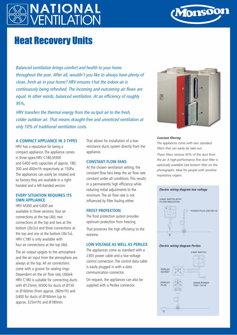
Constant filtering
The appliances come with two standard
filters that can easily be take out.
These filters remove 95% of the dust from
the air. A high-performance fine dust filter is
optionally available (see bottom filter on the
photograph). Ideal for people with sensitive
respiratory organs.
3-WAY SWITCH WITH
FILTER INDICATION
POWER PLUG 230V/50 HZ
Electric wiring diagram low voltage
PERILEX
SOCKET
PERILEX
PLUG
3-WAY SWITCH
MAINS POWER
230V / 50 HZ
Electric wiring diagram Perilex
Heat Recovery Units

3
KEY
1. Heated outdoor air to the bedroom and
the sitting room
2. Discharge foul air
3. Discharge foul air from kitchen, bathroom
and toilet
4. Supply outdoor air
5. Filters
6. Heat exchanger
7. Control pcb
8. Display
9. Direct current fans for constant volume
10. Condensate discharge
Settings display
The appliances come with a display for
setting and reading out functions for
increased ease of installation.
A cable kit and a computer program are
available for servicing purposes.
Naturally 95% efficiency
The synthetic heat exchanger transfers 95%
of the heat, which makes further heating of
the ventilation air superfluous (measured
under NEN 5138).
The EPS contribution is approx. 0.3.
The appliance in the picture is
the HRV M300 4b R
6
9
10
8
75
4
12
3
Technical specifications
Appliance C180 M300 G400
Ventilation capacity at 150 Pa [m3/h] Maximum 180 Maximum 300 Maximum 400
Rated power [W] (dependent on setting) 120 at 150m3/h (at 150 Pa) 175 at 300m3/h (at 150 Pa) 300 at 400m3/h (at 150 Pa)
Dimension duct connection [mm] Ø125 Ø150 and Ø160 Ø160 and Ø180
H x W x D [mm] 600 x 560 x 290602 x 675 x 420
(with bypass 500)
602 x 675 x 430
(with bypass 510)
Weight [kg] 25 31 32
Temperature efficiency [%] 95 95 95

4
HRV M300 and G400 4b R
HRV M300 and G400 3b/1o R
HRV M300 and G400 2b/2o R
HRV C180 4b R
KEY
I To dwelling
II To atmosphere
III From dwelling
IV From atmosphere
V Electric connections
VI Condensate discharge
DEMAND-CONTROLLEDVENTILATION
Usually the input ventilation air is divided
on the basis of the size of the various
rooms. The fresh outdoor air to those
rooms is really needed. That can be
achieved with demand-controlled
ventilation based on occupation
(CO2 measurement) or time programming
(clock function). A TNO certificate of
equivalence indicates that the EPC
advantage from such a controlled demand
system is 0.072 (2-zone time control) to
0.081 (2-zone CO2 control).
HOW IT WORKS
When the air quality is good, there is no
need for ventilation. The air quality
deteriorates when people are present, for
instance in the living room. In that case,
first the available ventilation air will be
sent to the living room in an intelligent
manner. Only when that appears to be
insufficient, the quantity of ventilation air
will be increased. That means customised
ventilation; the available ventilation air is
sent to the room where the ventilation air
is needed. A lower ventilation flow rate
means a lower energy consumption and a
lower sound level.
REMOTE CONTROL CBB
Communication between the various
components is arranged through the
Zigbee protocol. The
Zigbee protocol
is a wireless
communication
system. All
components, so
also the remote
control CBB (Control Panel), are
connected to a wall socket.
Operation
• Automatic based on presence
(CO2 measurement). CO2 sensors
determine the ventilation air flow rate.
At night, the ventilation in the living
room is reduced to the minimum and,
conversely, can be increased in the
bedrooms, without the high flow rate
causing additional noise nuisance.
• Automatic based on a time program
(clock function). A menu enables
adjustment of the control damper
settings for every day. The user can set
six time blocks per day.
• Manual control. The fan setting can
directly be changed by turning the
rotary knob on the remote control CBB.
OpenTherm
Control box
Renovent
Sleeping
zone
CO2 sensor
Damper
Control signal
Living zone
CO2 sensor
Setup with CO2-sensor
OpenTherm
Control box
Renovent
Sleeping
zone
Damper
Control signal
Living zone
Clock
Setup with clock function
Type A B C D E F G H I J K L M
C180 213 77 79 560 75 125 45 600 50 210 290 455 168
M300 321 121 165 675 89 99 45 602 210 385 420 445 -
G400 336 126 165 675 89 114 53 602 220 385 430 455 -
Dimensions of HRV C180, M300 and G400 (in mm)

ACCESSORIES FOR BALANCEDVENTILATION WITH HEATRECOVERY
Systems has developed
and selected appliance-specific accessories
that can be used to create an excellent
installation. Starting points are quality and
ease of use and assembly.
BYPASS UNIT FOR NIGHTVENTILATION
HRV M300 and G400 are
available ex factory with a bypass for
night ventilation that shuts off almost
completely. In summer, this bypass unit
ensures that cool night air replaces in so
far as possible the indoor air that has
been heated during the day. The air is
routed through the bypass unit. The
appliance comes with an automatic
control system that opens and closes the
bypass valve.
A bypass unit can also be retrofitted by
the installer or the user. This bypass unit
leads roughly 70% of the input air around
the HRV heat exchanger.
3-WAY SWITCH WITH FILTERINDICATION
The 3-way switch allows the user to
choose between three modes:
1. absence mode,
2. presence mode and
3. cooking/showering mode.
The 3-way switch is connected quickly and
easily on the outside of the appliance
using a data cable and a connector. That
makes connecting quick and easy. In
addition, it is possible to connect several
switches, for instance in the bathroom. For
convenience of the occupant, a 3-way
switch is available with a filter indicator
light. That shows when the filter has to be
cleaned.
WIRELESS REMOTE CONTROL
A radiographically operated remote
control is available as well. It can control
the ventilation system from anywhere in
the house without electric provisions.
Several remote controls (transmitters) can
be set for one receiver, for instance in the
bathroom as well as in the kitchen.
ADDITIONAL CONTROL OPTIONS
HRV M300 and G400 can be
extended with an option pcb. This pcb can
be used to control various accessories, for
instance a preheater and/or postheater
(1000W), a damper for sending extra
ventilation air to certain rooms or an
emergency contact. In addition, the option
pcb has an input for a CO2 sensor and a
humidity sensor.
ACOUSTIC FLEXIBLE HOSE
A good ventilation system should not
cause noise nuisance. Based on laboratory
and practice measurements, can
supply specially developed acoustic hoses
that give the best results in combination
with the HRV. These hoses come in
Ø125mm, Ø150mm, Ø160mm and
Ø180mm in boxes of 10m, but also in
finished sections from 1m. Connection kits
have been composed for ease of assembly
of the HRV. We strongly advise
against the use of other acoustic hoses.
SOUND ENGINEERING DATA
When using 1m of acoustic
flexible hose, the following sound pressure
can be expected in a living room
(measured under ISO 7235), expressed in
dB(A).
5
Sound pressure HRV M300
Frequency [Hz] 125 250 500 1000 2000 4000 Tot [dB(A)]
100m3/h, 40 Pa -5 -6.3 4.5 8.4 -13.2 -17.5 10.2
150m3/h, 60 Pa 0.6 0 10.4 11.2 -5.3 -9.8 14.3
300m3/h, 160 Pa 11.8 13.8 24 22.2 10.3 5 26.7
Sound pressure HRV G400
Frequency [Hz] 125 250 500 1000 2000 4000 Tot [dB(A)]
100m3/h, 40 Pa -5 -6.3 4.5 8.4 -13.2 -17.5 10.2
150m3/h, 60 Pa 5.7 6.2 14 15.2 2 -2.5 18.3
300m3/h, 160 Pa 18.1 23.8 33.9 30.8 12.6 23.8 36.3
Ø125mm Ø150mm Ø160mm Ø180mm
Finished section acoustic insulating hose 2 x 1m 2 x 1m 2 x 1m 2 x 1.5m
Thermally insulating hose - - 1 x 3m 1 x 3m
Universal clamping strips 4 4 8 8
Armaflex tape 1.25m 1.25m 1.25m 1.25m
Contents connecting kits HRV C180, M300 & G400
HRV HEAT RECOVERY DUCTSYSTEM
The revolutionary HRV heat recovery
synthetic duct system is available in
Ø125mm, Ø150mm and Ø180 mm. The
material insulates and allows creation of a
neat system. The availability of long
sections (2.25m) makes the HRV heat
recovery duct system very quick and easy
to assemble with only a little waste. Also
under complicated assembly conditions,
the flexible material offers practical
possibilities. In addition, the long socket
sleeves and compact bends (15°, 30°, 45°
and 90°) take up less space and make the
entire system look beautiful. The ducts are
easy to inspect and clean through a
special inspection sleeve that can also be
used as fixation bracket. In addition, the
supplied cutting template ensures that the
ducts can always be cut simply and
correctly. The HRV heat recovery pipe is
used for the ducts from and to the
atmosphere.
6
INCORPORATED DUCTS
developed a comprehensive range
of incorporated ducts for the ventilation
market, complete with all required
accessories such as couplings, end and
sliding pieces, bends and connections. The
sophisticated design, dimensions and
spacers of the system result in a low air
resistance, which is important for proper
performance of the ventilation system.
All ducts have a height of 80mm and they
are available in widths of 165, 180, 205
and 240mm. All parts are made of
galvanised sheet steel.
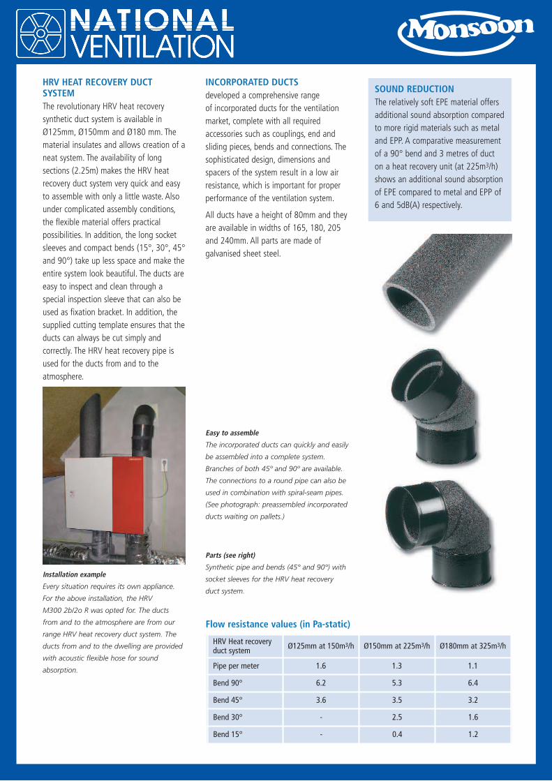
SOUND REDUCTION
The relatively soft EPE material offers
additional sound absorption compared
to more rigid materials such as metal
and EPP. A comparative measurement
of a 90° bend and 3 metres of duct
on a heat recovery unit (at 225m3/h)
shows an additional sound absorption
of EPE compared to metal and EPP of
6 and 5dB(A) respectively.
Installation example
Every situation requires its own appliance.
For the above installation, the HRV
M300 2b/2o R was opted for. The ducts
from and to the atmosphere are from our
range HRV heat recovery duct system. The
ducts from and to the dwelling are provided
with acoustic flexible hose for sound
absorption.
Easy to assemble
The incorporated ducts can quickly and easily
be assembled into a complete system.
Branches of both 45º and 90º are available.
The connections to a round pipe can also be
used in combination with spiral-seam pipes.
(See photograph: preassembled incorporated
ducts waiting on pallets.)
Parts (see right)
Synthetic pipe and bends (45° and 90°) with
socket sleeves for the HRV heat recovery
duct system.
HRV Heat recoveryduct system
Ø125mm at 150m3/h Ø150mm at 225m3/h Ø180mm at 325m3/h
Pipe per meter 1.6 1.3 1.1
Bend 90° 6.2 5.3 6.4
Bend 45° 3.6 3.5 3.2
Bend 30° - 2.5 1.6
Bend 15° - 0.4 1.2
Flow resistance values (in Pa-static)
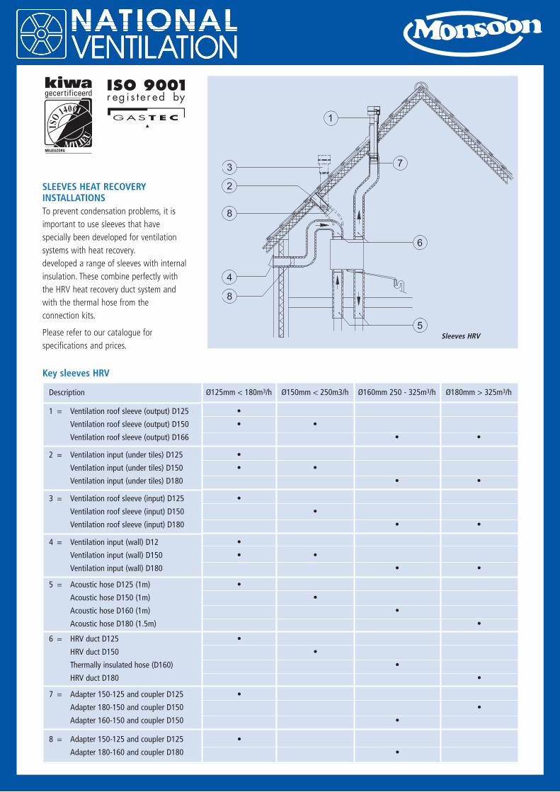
SLEEVES HEAT RECOVERYINSTALLATIONS
To prevent condensation problems, it is
important to use sleeves that have
specially been developed for ventilation
systems with heat recovery.
developed a range of sleeves with internal
insulation. These combine perfectly with
the HRV heat recovery duct system and
with the thermal hose from the
connection kits.
Please refer to our catalogue for
specifications and prices.
7
Sleeves HRV
MILIEUZORG
gecertificeerd
MILIEU
ISO
14001
MILIEU
ISO
14001
Description
1 = Ventilation roof sleeve (output) D125
Ventilation roof sleeve (output) D150
Ventilation roof sleeve (output) D166
2 = Ventilation input (under tiles) D125
Ventilation input (under tiles) D150
Ventilation input (under tiles) D180
3 = Ventilation roof sleeve (input) D125
Ventilation roof sleeve (input) D150
Ventilation roof sleeve (input) D180
4 = Ventilation input (wall) D12
Ventilation input (wall) D150
Ventilation input (wall) D180
5 = Acoustic hose D125 (1m)
Acoustic hose D150 (1m)
Acoustic hose D160 (1m)
Acoustic hose D180 (1.5m)
6 = HRV duct D125
HRV duct D150
Thermally insulated hose (D160)
HRV duct D180
7 = Adapter 150-125 and coupler D125
Adapter 180-150 and coupler D150
Adapter 160-150 and coupler D150
8 = Adapter 150-125 and coupler D125
Adapter 180-160 and coupler D180
Ø125mm < 180m3/h Ø150mm < 250m3/h Ø160mm 250 - 325m3/h Ø180mm > 325m3/h
•
• •
• •
•
• •
• •
•
•
• •
•
• •
• •
•
•
•
•
•
•
•
•
•
•
•
•
•
Key sleeves HRV