High-capacity Switch Capable of Handling 20 A Loads with ... · High-capacity Switch Capable of...
7
CSM_A_DS_E_2_1 1 General-purpose Basic Switch A High-capacity Switch Capable of Handling 20 A Loads with Large Inrush Currents • Same shape as OMRON Z Basic Switches except in pin plunger position, yet endures inrush currents as large as 75 A. Be sure to read Safety Precautions on page 5 and Safety Precautions for All Basic Switches. Specifications Ratings Note: 1. The above values are for steady-state current. 2. Inductive load has a power factor of 0.4 min. (AC) and a time constant of 7 ms max. (DC). 3. Lamp load has an inrush current of 10 times the steady-state current. 4. Motor load has an inrush current of 6 times the steady-state current. 5. The ratings values apply under the following test conditions: (1) Ambient temperature: 20±2°C (2) Ambient humidity: 65±5%RH (3) Operating frequency: 20 operations/min Certified Standard Ratings Ask your OMRON representative for information on certified models. UL/CSA (General ratings only) Model Number Structure Model Number Legend A - 20 G @ - @ (1) (2) (3) (4) (1) Ratings 20 : 20 A (250 VAC) (2) Contact Gap G : 0.5 m (3) Actuator None : Pin plunger D : Short spring plunger Q : Panel mount plunger Q21 : Panel mount cross roller plunger Q22 : Panel mount roller plunger V : Hinge lever V2 : Hinge roller lever V21 : Short hinge lever V22 : Short hinge roller lever (4) Terminals None : Solder terminal B : Screw terminal (with toothed washer) Ordering Information Terminal Solder terminal Screw terminal (-B) Actuator Model Model Pin plunger A-20G A-20G-B Short spring plunger A-20GD A-20GD-B Panel mount plunger A-20GQ A-20GQ-B Panel mount roller plunger A-20GQ22 A-20GQ22-B Panel mount cross roller plunger --- A-20GQ21-B Short hinge lever A-20GV21 A-20GV21-B Hinge lever A-20GV A-20GV-B Short hinge roller lever A-20GV22 A-20GV22-B Hinge roller lever A-20GV2 A-20GV2-B Rated voltage (V) Non-inductive load (A) Inductive load (A) Resistive load Lamp load Inductive load Motor load NC NO NC NO NC NO NC NO 125 VAC 250 VAC 500 VAC 20 20 15 7.5 7.5 4 20 20 10 12.5 8.3 2 8 VDC 14 VDC 30 VDC 125 VDC 250 VDC 20 20 6 0.5 0.25 3 3 3 0.5 0.25 1.5 1.5 1.5 0.5 0.25 20 15 5 0.05 0.03 12.5 12.5 5 0.05 0.03 Rated voltage Model A-20G 125 VAC 1 HP 10 A "L" 250 VAC 2 HP 480 VAC 20 A 125 VDC 0.5 A 250 VDC 0.25 A Accessories (Terminal Covers, and Separators): Refer to Z/A/X/DZ Common Accessories.
Transcript of High-capacity Switch Capable of Handling 20 A Loads with ... · High-capacity Switch Capable of...

CSM_A_DS_E_2_1
General-purpose Basic Switch
A
High-capacity Switch Capable of Handling 20 A Loads with Large Inrush Currents• Same shape as OMRON Z Basic Switches except in pin plungerposition, yet endures inrush currents as large as 75 A.
Be sure to read Safety Precautions on page 5 and Safety Precautions for All Basic Switches.
Specifications
Ratings
Note: 1. The above values are for steady-state current.2. Inductive load has a power factor of 0.4 min. (AC) and a time constant
of 7 ms max. (DC).3. Lamp load has an inrush current of 10 times the steady-state current.4. Motor load has an inrush current of 6 times the steady-state current.5. The ratings values apply under the following test conditions:
(1) Ambient temperature: 20±2°C(2) Ambient humidity: 65±5%RH(3) Operating frequency: 20 operations/min
Certified Standard RatingsAsk your OMRON representative for information on certified models.UL/CSA (General ratings only)
Model Number Structure
Model Number LegendA - 20 G @ - @
(1) (2) (3) (4)
(1) Ratings20 : 20 A (250 VAC)
(2) Contact GapG : 0.5 m
(3) ActuatorNone : Pin plunger
D : Short spring plungerQ : Panel mount plunger
Q21 : Panel mount cross roller plungerQ22 : Panel mount roller plunger
V : Hinge leverV2 : Hinge roller lever
V21 : Short hinge leverV22 : Short hinge roller lever
(4) TerminalsNone : Solder terminal
B : Screw terminal (with toothed washer)
Ordering Information
Terminal Solder terminal Screw terminal (-B)
Actuator Model Model
Pin plunger A-20G A-20G-B
Short spring plunger A-20GD A-20GD-B
Panel mount plunger A-20GQ A-20GQ-B
Panel mount roller plunger A-20GQ22 A-20GQ22-B
Panel mount cross roller plunger --- A-20GQ21-B
Short hinge lever A-20GV21 A-20GV21-B
Hinge lever A-20GV A-20GV-B
Short hinge roller lever A-20GV22 A-20GV22-B
Hinge roller lever A-20GV2 A-20GV2-B
Rated voltage
(V)
Non-inductive load (A) Inductive load (A)
Resistive load Lamp load Inductive
load Motor load
NC NO NC NO NC NO NC NO
125 VAC250 VAC500 VAC
202015
7.57.54
202010
12.58.32
8 VDC14 VDC30 VDC125 VDC250 VDC
2020
60.50.25
3330.50.25
1.51.51.50.50.25
2015
50.050.03
12.512.5
50.050.03
Rated voltage Model A-20G
125 VAC 1 HP 10 A "L"
250 VAC 2 HP
480 VAC 20 A
125 VDC 0.5 A
250 VDC 0.25 A
Accessories (Terminal Covers, and Separators): Refer to Z/A/X/DZ Common Accessories.
1

A
Characteristics
*1. The value is for the pin plunger. (Contact your OMRON representative for other models.)
*2. Malfunction: 1 ms max.
Contact Specification
Engineering DataMechanical Durability (A-20G)
Electrical Durability (A-20G)
Structure
Contact Form (SPDT)
Dimensions (Unit: mm)
TerminalsScrew Terminals (-B)
Solder Terminal (-A) ("-A" is not included in the model numbers.)
Note: 1. Appropriate terminal screw tightening torque: 0.78 to 1.18 N·m.2. Unless otherwise specified, a tolerance of ±0.4 mm applies to all dimensions.
Mounting HolesUse M4 mounting screws with plane washers or spring washers to securely mount the Switch. Tighten the screws to a torque of 1.18 to 1.47 N·m.
The Switch can be panel mounted, provided that the hexagonal nut of the actuator is tightened to a torque of 2.94 to 4.9 N·m.
Operating speed 0.01 mm to 1m/s *1
Operating frequency
Mechanical 240 operations/min
Electrical 20 operations/min
Insulation resistance 100 MΩ min. (at 500 VDC)
Contact resistance 15 mΩ max. (initial value)
Dielectric strength
1,000 VAC, 50/60 Hz for 1 min between terminals of the same polarity2,000 VAC, 50/60 Hz for 1 min between the current-carrying metal parts and the ground, and between each terminal and non-current-carrying metal parts
Vibration resistance Malfunction 10 to 55 Hz, 1.5-mm double amplitude *2
Shock re-sistance
Destruction 1,000 m/s2 max.
Malfunction 300 m/s2 max. *1 *2
DurabilityMechanical 1,000,000 operations min.
Electrical 500,000 operations min.
Degree of protection IP00
Degree of protection against electric shock Class I
Proof tracking index (PTI) 175
Ambient operating temperature −25°C to 80°C (with no icing)
Ambient operating humidity 35% to 85%RH
Weight Approx. 22 to 58 g
Contacts
Shape Rivet
Material Silver alloy
Gap (standard value) 0.5 mm
Inrush currentNC 75 A max.
NO 75 A max.
50
70
100
30
10
500
700
1,000
300
0.20.1 0.4 0.6 0.80.3 0.5 0.70
Dur
abili
ty (
x10
4 o
pera
tions
)
Overtravel (mm)
Ambient temperature: 20±2°CAmbient humidity: 65±5%RHWithout loadOperating frequency: 240 operations/min
50
70
100
30
10
500
700
1,000
300
5 2510 15 200
Dur
abili
ty (
x10
4 o
pera
tions
)
Switching current (A)
Ambient temperature: 20±2°CAmbient humidity: 65±5%RHOperating frequency: 20 operations/min
250 VAC, cosφ = 0.4
250 VAC, cosφ = 1
125 VAC, cosφ = 1
125 VAC, cosφ = 0.4
COM NC
NO
COM NO NC
1 3 2
17.45±0.2
49.2
9.2
20 20
Three, M4 × 5.5Terminal screws(with toothed washer)
COMNO
NC
1
2
3
11.9
6.4
49.2
25.4±0.1 17.45±0.2
Panel Mount Plunger Panel Mount Roller Plunger
25.4±0.1
Two, 4.2 dia. mountingholes or M4
12.5 dia.+0.20 12.5 dia.
13+0.20
+0.20
+0.205
2

A
Dimensions and Operating CharacteristicsThe models, illustrations, and graphics are for screw-terminal models. (The dimensions for models that are omitted here are the same as for pin-plunger models.)
Note: Unless otherwise specified, a tolerance of ±0.4 mm applies to all dimensions.
Operating Characteristics Model A-20G-B A-20GD-B A-20GQ-B A-20GQ22-B A-20GQ21-B
Operating force OFRelease force RF min.Pretravel PT max.Over Travel OT min.Movement differential MD max.
3.92 to 6.13 N2.79 N1.3 mm0.25 mm0.2 mm
3.92 to 6.13 N2.79 N1.3 mm3 mm
0.2 mm
3.92 to 6.13 N2.79 N1.3 mm5.6 mm0.2 mm
6.18 N max.2.75 N1.3 mm3.58 mm0.35 mm
6.18 N max.2.75 N1.3 mm3.58 mm0.35 mm
Operating Position OP 16.3±0.4 mm 26.2±0.5 mm 21.8±0.8 mm 33.4±1.2 mm 33.4±1.2 mm
49.2
11.925.4±0.1
19.05±0.25
24.2
17.45±0.2
OP
PT
9.2
2.3SR *+0.075−0.025
* Stainless-steel plunger
2.3 dia.4.2 dia. hole
+0.075−0.0254.2 dia.
+0.1−0.054.36 dia.
Pin PlungerA-20G-B
24.2
7.5
OP
PT 7.15dia.
11.2 dia.
15 dia.
11.9SR *
19.05±0.25
* Stainless-steel plunger
Short Spring PlungerA-20GD-B
OP
16.3
*213.1
PT 8.35 dia.11.9SR *1
19.05±0.25
M12 × 1 mounting screw
16 dia.
*1 Stainless-steel plunger*2 Incomplete screw part with a maximum length of 1.5 mm.
Two hexagon nuts(2 t × 14 width across flats)
Two lock nuts(2 t × 15.6 width across flats)
Panel Mount PlungerA-20GQ-B Note: Do not use both M12
mounting screw and mounting holes at the same time.
OP
16.3
*215.5
PT19.05±0.25
M12 × 1 mounting screw
Two hexagon nuts(3 t × 17 width across flats)
12.7 dia. × 4.8 *1
16 dia.
*1 Stainless-steel roller*2 Incomplete screw part with a maximum length of 1.5 mm.
Panel Mount Roller PlungerA-20GQ22-B
Note: Do not use both M12 mounting screw and mounting holes at the same time.
OP
16.3
*215.5
PT19.05±0.25
M12 × 1 mounting screw
Two hexagon nuts(3 t × 17 width across flats)
12.7 dia. × 4.8 *1
16 dia.
*1 Stainless-steel roller*2 Incomplete screw part with a maximum length of 1.5 mm.
Panel Mount Cross Roller PlungerA-20GQ21-B
Note: Do not use both M12 mounting screw and mounting holes at the same time.
3
A
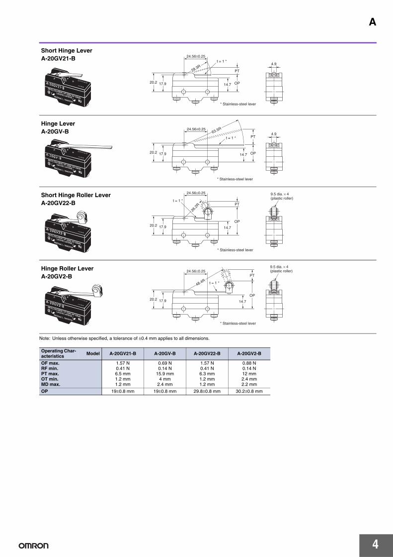
Note: Unless otherwise specified, a tolerance of ±0.4 mm applies to all dimensions.
Operating Char-acteristics Model A-20GV21-B A-20GV-B A-20GV22-B A-20GV2-B
OF max.RF min.PT max.OT min.MD max.
1.57 N0.41 N6.5 mm1.2 mm1.2 mm
0.69 N0.14 N
15.9 mm4 mm
2.4 mm
1.57 N0.41 N6.3 mm1.2 mm1.2 mm
0.88 N0.14 N12 mm2.4 mm2.2 mm
OP 19±0.8 mm 19±0.8 mm 29.8±0.8 mm 30.2±0.8 mm
4.9
17.920.2
28.3R
14.7 OP
PT
24.56±0.25
* Stainless-steel lever
t = 1 *
Short Hinge LeverA-20GV21-B
4.9
17.920.2
63.5R
14.7 OP
PT
24.56±0.25
* Stainless-steel lever
t = 1 *
Hinge LeverA-20GV-B
17.920.214.7
OP
PT
26.2
R
24.56±0.25
* Stainless-steel lever
9.5 dia. × 4 (plastic roller)
t = 1 *Short Hinge Roller LeverA-20GV22-B
17.920.214.7
OP
PT
48.4R
24.56±0.25
* Stainless-steel lever
9.5 dia. × 4 (plastic roller)
t = 1 *
Hinge Roller LeverA-20GV2-B
4
A
Safety PrecautionsRefer to Safety Precautions for All Basic Switches.
Terminal ConnectionWhen soldering lead wires to the Switch, make sure that the capacity of the soldering iron is 60 W maximum. Do not take more than 5 s to solder any part of the Switch. The characteristics of the Switch will deteriorate if a soldering iron with a capacity of more than 60 W is applied to any part of the Switch for 5 s or more.
Operation• Make sure that the switching frequency or speed is within the
specified range.1.If the switching speed is extremely slow, the contact may not be
switched smoothly, which may result in a contact failure or contact welding.
2.If the switching speed is extremely fast, switching shock may damage the Switch soon. If the switching frequency is too high, the contact may not catch up with the speed.
The rated permissible switching speed and frequency indicate the switching reliability of the Switch.The life of a Switch is determined at the specified switching speed. The life varies with the switching speed and frequency even when they are within the permissible ranges. In order to determine the life of a Switch model to be applied to a particular use, it is best to conduct an appropriate durability test on some samples of the model under actual conditions.
• Make sure that the actuator travel does not exceed the permissible OT position. The operating stroke must be set to 70% to 100% of the rated OT.
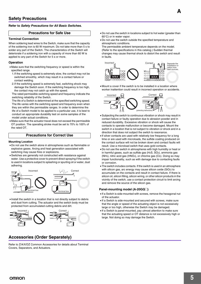
Mounting Location• Do not use the switch alone in atmospheres such as flammable or
explosive gases. Arcing and heat generation associated with switching may cause fires or explosions.
• Switches are generally not constructed with resistance against water. Use a protective cover to prevent direct spraying if the switch is used in locations subject to splashing or spurting oil or water, dust adhering.
• Install the switch in a location that is not directly subject to debris and dust from cutting. The actuator and the switch body must be protected from accumulated cutting debris and dirt.
• Do not use the switch in locations subject to hot water (greater than 60°C) or in water vapor.
• Do not use the switch outside the specified temperature and atmospheric conditions.The permissible ambient temperature depends on the model. (Refer to the specifications in this catalog.) Sudden thermal changes may cause thermal shock to distort the switch and result in faults.
• Mount a cover if the switch is to be installed in a location where worker inattention could result in incorrect operation or accidents.
• Subjecting the switch to continuous vibration or shock may result in contact failure or faulty operation due to abrasion powder and in reduced durability. Excessive vibration or shock will cause the contacts to operate malfunction or become damaged. Mount the switch in a location that is not subject to vibration or shock and in a direction that does not subject the switch to resonance.
• If silver contacts are used with relatively low frequency for a long time or are used with microloads, the sulfide coating produced on the contact surface will not be broken down and contact faults will result. Use a microload switch that uses gold contacts.
• Do not use the switch in atmospheres with high humidity or heat or in harmful gases, such as sulfide gas (H2S, SO2), ammonia gas (NH3), nitric acid gas (HNO3), or chlorine gas (Cl2). Doing so may impair functionality, such as with damage due to contacting faults or corrosion.
• The switch includes contacts. If the switch is used in an atmosphere with silicon gas, arc energy may cause silicon oxide (SiO2) to accumulate on the contacts and result in contact failure. If there is silicon oil, silicon filling, silicon wiring, or other silicon products in the vicinity of the switch, use a contact protection circuit to limit arcing and remove the source of the silicon gas.
Panel-mounting model (A-20GQ@)• If a Switch is side-mounted with screws, remove the hexagonal nut
of the actuator.• If a Switch is side-mounted and secured with screws, make sure
that the angle or speed of the actuating object is not excessively large or too high, otherwise the Switch may be damaged.
• If a Switch is panel-mounted, pay utmost attention to make sure that the actuating speed or OT distance is not excessively high or large. Not doing so may damage the Switch.
Accessories (Order Separately)
Refer to Z/A/X/DZ Common Accessories for details about Terminal Covers, Separators, and Actuators.
Precautions for Safe Use
Precautions for Correct Use
Terminal box Terminal box
Incorrect Correct
Incorrect Correct
Incorrect Separate the installation lo-cation from heat sources.
Correct
Correct
(preventing malfunctions)
Incorrect
5

Terms and Conditions of Sale1. Offer; Acceptance. These terms and conditions (these "Terms") are deemed
part of all quotes, agreements, purchase orders, acknowledgments, price lists,catalogs, manuals, brochures and other documents, whether electronic or inwriting, relating to the sale of products or services (collectively, the "Products")by Omron Electronics LLC and its subsidiary companies (“Omron”). Omronobjects to any terms or conditions proposed in Buyer’s purchase order or otherdocuments which are inconsistent with, or in addition to, these Terms.
2. Prices; Payment Terms. All prices stated are current, subject to change with-out notice by Omron. Omron reserves the right to increase or decrease priceson any unshipped portions of outstanding orders. Payments for Products aredue net 30 days unless otherwise stated in the invoice.
3. Discounts. Cash discounts, if any, will apply only on the net amount of invoicessent to Buyer after deducting transportation charges, taxes and duties, and willbe allowed only if (i) the invoice is paid according to Omron’s payment termsand (ii) Buyer has no past due amounts.
4. Interest. Omron, at its option, may charge Buyer 1-1/2% interest per month orthe maximum legal rate, whichever is less, on any balance not paid within thestated terms.
5. Orders. Omron will accept no order less than $200 net billing. 6. Governmental Approvals. Buyer shall be responsible for, and shall bear all
costs involved in, obtaining any government approvals required for the impor-tation or sale of the Products.
7. Taxes. All taxes, duties and other governmental charges (other than generalreal property and income taxes), including any interest or penalties thereon,imposed directly or indirectly on Omron or required to be collected directly orindirectly by Omron for the manufacture, production, sale, delivery, importa-tion, consumption or use of the Products sold hereunder (including customsduties and sales, excise, use, turnover and license taxes) shall be charged toand remitted by Buyer to Omron.
8. Financial. If the financial position of Buyer at any time becomes unsatisfactoryto Omron, Omron reserves the right to stop shipments or require satisfactorysecurity or payment in advance. If Buyer fails to make payment or otherwisecomply with these Terms or any related agreement, Omron may (without liabil-ity and in addition to other remedies) cancel any unshipped portion of Prod-ucts sold hereunder and stop any Products in transit until Buyer pays allamounts, including amounts payable hereunder, whether or not then due,which are owing to it by Buyer. Buyer shall in any event remain liable for allunpaid accounts.
9. Cancellation; Etc. Orders are not subject to rescheduling or cancellationunless Buyer indemnifies Omron against all related costs or expenses.
10. Force Majeure. Omron shall not be liable for any delay or failure in deliveryresulting from causes beyond its control, including earthquakes, fires, floods,strikes or other labor disputes, shortage of labor or materials, accidents tomachinery, acts of sabotage, riots, delay in or lack of transportation or therequirements of any government authority.
11. Shipping; Delivery. Unless otherwise expressly agreed in writing by Omron:a. Shipments shall be by a carrier selected by Omron; Omron will not drop ship
except in “break down” situations.b. Such carrier shall act as the agent of Buyer and delivery to such carrier shall
constitute delivery to Buyer;c. All sales and shipments of Products shall be FOB shipping point (unless oth-
erwise stated in writing by Omron), at which point title and risk of loss shallpass from Omron to Buyer; provided that Omron shall retain a security inter-est in the Products until the full purchase price is paid;
d. Delivery and shipping dates are estimates only; ande. Omron will package Products as it deems proper for protection against nor-
mal handling and extra charges apply to special conditions.12. Claims. Any claim by Buyer against Omron for shortage or damage to the
Products occurring before delivery to the carrier must be presented in writingto Omron within 30 days of receipt of shipment and include the original trans-portation bill signed by the carrier noting that the carrier received the Productsfrom Omron in the condition claimed.
13. Warranties. (a) Exclusive Warranty. Omron’s exclusive warranty is that theProducts will be free from defects in materials and workmanship for a period oftwelve months from the date of sale by Omron (or such other period expressedin writing by Omron). Omron disclaims all other warranties, express or implied.(b) Limitations. OMRON MAKES NO WARRANTY OR REPRESENTATION,EXPRESS OR IMPLIED, ABOUT NON-INFRINGEMENT, MERCHANTABIL-
ITY OR FITNESS FOR A PARTICULAR PURPOSE OF THE PRODUCTS.BUYER ACKNOWLEDGES THAT IT ALONE HAS DETERMINED THAT THEPRODUCTS WILL SUITABLY MEET THE REQUIREMENTS OF THEIRINTENDED USE. Omron further disclaims all warranties and responsibility ofany type for claims or expenses based on infringement by the Products or oth-erwise of any intellectual property right. (c) Buyer Remedy. Omron’s sole obli-gation hereunder shall be, at Omron’s election, to (i) replace (in the formoriginally shipped with Buyer responsible for labor charges for removal orreplacement thereof) the non-complying Product, (ii) repair the non-complyingProduct, or (iii) repay or credit Buyer an amount equal to the purchase price ofthe non-complying Product; provided that in no event shall Omron be responsi-ble for warranty, repair, indemnity or any other claims or expenses regardingthe Products unless Omron’s analysis confirms that the Products were prop-erly handled, stored, installed and maintained and not subject to contamina-tion, abuse, misuse or inappropriate modification. Return of any Products byBuyer must be approved in writing by Omron before shipment. Omron Compa-nies shall not be liable for the suitability or unsuitability or the results from theuse of Products in combination with any electrical or electronic components,circuits, system assemblies or any other materials or substances or environ-ments. Any advice, recommendations or information given orally or in writing,are not to be construed as an amendment or addition to the above warranty.See http://www.omron247.com or contact your Omron representative for pub-lished information.
14. Limitation on Liability; Etc. OMRON COMPANIES SHALL NOT BE LIABLEFOR SPECIAL, INDIRECT, INCIDENTAL, OR CONSEQUENTIAL DAMAGES,LOSS OF PROFITS OR PRODUCTION OR COMMERCIAL LOSS IN ANYWAY CONNECTED WITH THE PRODUCTS, WHETHER SUCH CLAIM ISBASED IN CONTRACT, WARRANTY, NEGLIGENCE OR STRICT LIABILITY.Further, in no event shall liability of Omron Companies exceed the individualprice of the Product on which liability is asserted.
15. Indemnities. Buyer shall indemnify and hold harmless Omron Companies andtheir employees from and against all liabilities, losses, claims, costs andexpenses (including attorney's fees and expenses) related to any claim, inves-tigation, litigation or proceeding (whether or not Omron is a party) which arisesor is alleged to arise from Buyer's acts or omissions under these Terms or inany way with respect to the Products. Without limiting the foregoing, Buyer (atits own expense) shall indemnify and hold harmless Omron and defend or set-tle any action brought against such Companies to the extent based on a claimthat any Product made to Buyer specifications infringed intellectual propertyrights of another party.
16. Property; Confidentiality. Any intellectual property in the Products is the exclu-sive property of Omron Companies and Buyer shall not attempt to duplicate itin any way without the written permission of Omron. Notwithstanding anycharges to Buyer for engineering or tooling, all engineering and tooling shallremain the exclusive property of Omron. All information and materials suppliedby Omron to Buyer relating to the Products are confidential and proprietary,and Buyer shall limit distribution thereof to its trusted employees and strictlyprevent disclosure to any third party.
17. Export Controls. Buyer shall comply with all applicable laws, regulations andlicenses regarding (i) export of products or information; (iii) sale of products to“forbidden” or other proscribed persons; and (ii) disclosure to non-citizens ofregulated technology or information.
18. Miscellaneous. (a) Waiver. No failure or delay by Omron in exercising any rightand no course of dealing between Buyer and Omron shall operate as a waiverof rights by Omron. (b) Assignment. Buyer may not assign its rights hereunderwithout Omron's written consent. (c) Law. These Terms are governed by thelaw of the jurisdiction of the home office of the Omron company from whichBuyer is purchasing the Products (without regard to conflict of law princi-ples). (d) Amendment. These Terms constitute the entire agreement betweenBuyer and Omron relating to the Products, and no provision may be changedor waived unless in writing signed by the parties. (e) Severability. If any provi-sion hereof is rendered ineffective or invalid, such provision shall not invalidateany other provision. (f) Setoff. Buyer shall have no right to set off any amountsagainst the amount owing in respect of this invoice. (g) Definitions. As usedherein, “including” means “including without limitation”; and “Omron Compa-nies” (or similar words) mean Omron Corporation and any direct or indirectsubsidiary or affiliate thereof.
Certain Precautions on Specifications and Use1. Suitability of Use. Omron Companies shall not be responsible for conformity
with any standards, codes or regulations which apply to the combination of theProduct in the Buyer’s application or use of the Product. At Buyer’s request,Omron will provide applicable third party certification documents identifyingratings and limitations of use which apply to the Product. This information byitself is not sufficient for a complete determination of the suitability of the Prod-uct in combination with the end product, machine, system, or other applicationor use. Buyer shall be solely responsible for determining appropriateness ofthe particular Product with respect to Buyer’s application, product or system.Buyer shall take application responsibility in all cases but the following is anon-exhaustive list of applications for which particular attention must be given:(i) Outdoor use, uses involving potential chemical contamination or electricalinterference, or conditions or uses not described in this document.(ii) Use in consumer products or any use in significant quantities. (iii) Energy control systems, combustion systems, railroad systems, aviationsystems, medical equipment, amusement machines, vehicles, safety equip-ment, and installations subject to separate industry or government regulations. (iv) Systems, machines and equipment that could present a risk to life or prop-erty. Please know and observe all prohibitions of use applicable to this Prod-uct. NEVER USE THE PRODUCT FOR AN APPLICATION INVOLVING SERIOUSRISK TO LIFE OR PROPERTY OR IN LARGE QUANTITIES WITHOUTENSURING THAT THE SYSTEM AS A WHOLE HAS BEEN DESIGNED TO
ADDRESS THE RISKS, AND THAT THE OMRON’S PRODUCT IS PROP-ERLY RATED AND INSTALLED FOR THE INTENDED USE WITHIN THEOVERALL EQUIPMENT OR SYSTEM.
2. Programmable Products. Omron Companies shall not be responsible for theuser’s programming of a programmable Product, or any consequence thereof.
3. Performance Data. Data presented in Omron Company websites, catalogsand other materials is provided as a guide for the user in determining suitabil-ity and does not constitute a warranty. It may represent the result of Omron’stest conditions, and the user must correlate it to actual application require-ments. Actual performance is subject to the Omron’s Warranty and Limitationsof Liability.
4. Change in Specifications. Product specifications and accessories may bechanged at any time based on improvements and other reasons. It is our prac-tice to change part numbers when published ratings or features are changed,or when significant construction changes are made. However, some specifica-tions of the Product may be changed without any notice. When in doubt, spe-cial part numbers may be assigned to fix or establish key specifications foryour application. Please consult with your Omron’s representative at any timeto confirm actual specifications of purchased Product.
5. Errors and Omissions. Information presented by Omron Companies has beenchecked and is believed to be accurate; however, no responsibility is assumedfor clerical, typographical or proofreading errors or omissions.

OMRON CANADA, INC. • HEAD OFFICEToronto, ON, Canada • 416.286.6465 • 866.986.6766 • www.omron247.com
OMRON ELECTRONICS DE MEXICO • HEAD OFFICEMéxico DF • 52.55.59.01.43.00 • 001.800.556.6766 • [email protected]
OMRON ELECTRONICS DE MEXICO • SALES OFFICEApodaca, N.L. • 52.81.11.56.99.20 • 001.800.556.6766 • [email protected]
OMRON ELETRÔNICA DO BRASIL LTDA • HEAD OFFICESão Paulo, SP, Brasil • 55.11.2101.6300 • www.omron.com.br
OMRON ARGENTINA • SALES OFFICECono Sur • 54.11.4783.5300
OMRON CHILE • SALES OFFICESantiago • 56.9.9917.3920
OTHER OMRON LATIN AMERICA SALES54.11.4783.5300
OMRON INDUSTRIAL AUTOMATION • THE AMERICAS HEADQUARTERSSchaumburg, IL USA • 847.843.7900 • 800.556.6766 • www.omron247.com
OMRON EUROpE B.V. • Wegalaan 67-69, NL-2132 JD, Hoofddorp, The Netherlands. • Tel: +31 (0) 23 568 13 00Fax: +31 (0) 23 568 13 88 • www.industrial.omron.eu
Cat. No. A_DS_E_2_1 11/08 Note: Specifications are subject to change. © 2011 Omron Electronics LLC Printed in U.S.A.