High-Amplitude Low-Cycle Fatigue in Concrete Sea Structures
15
High-Amplitude Low-Cycle Fatigue in Concrete Sea Structures Ben C. Gerwick, Jr. Consulting Construction Engineer San Francisco, California (Also, Professor of Civil Engineering, University of California at Berkeley) F ourteen prestressed concrete struc- tures are now in service as oil dril- ling, production, and storage platforms in the North Sea. Other fixed concrete structures are in service as offshore terminals, floating docks, floating ter- minals, breakwaters, and floating bridges in many parts of the world. These structures will typically be sub- jected to 2 x 10 8 cycles of waves during a normal service lifetime. At the same time, concepts are being developed for concrete structures in the Arctic regions, where they may be subjected to many extended periods of continuous crushing of sheet ice. One such structure, the Dome Petroleum's Tarsiut caisson-retained island, is cur- rently under construction in the Cana- dian Beaufort Sea. Such ice crushing may have a fre- quency of peak force development similar to the natural period of the structure.' If continuous crushing is as- sumed to act in one direction for 25 percent of the time over an ice regime lasting 4 months per year, such a structure could experience 10 7 cycles in a 50-year lifetime. In the case of waves, a probable long-term history of expected loadings can be developed, from which the stress ranges versus number of cycles (S-N curves) can be computed. In the case of Arctic ice, the distribution of ridges in the sheet and the forces and stresses acting on the structure are less well determined; however, a Poisson distribution appears probable 2 with rel- atively few large events interspersed among a large number of moderate and low cycles (see Fig. 1). The typical concrete sea structure, such as those in the North Sea, is so 82
Transcript of High-Amplitude Low-Cycle Fatigue in Concrete Sea Structures

High-Amplitude Low-CycleFatigue in ConcreteSea Structures
Ben C. Gerwick, Jr.Consulting Construction EngineerSan Francisco, California(Also, Professor of Civil Engineering,University of California at Berkeley)
F ourteen prestressed concrete struc-tures are now in service as oil dril-
ling, production, and storage platformsin the North Sea. Other fixed concretestructures are in service as offshoreterminals, floating docks, floating ter-minals, breakwaters, and floatingbridges in many parts of the world.These structures will typically be sub-jected to 2 x 10⁸ cycles of waves duringa normal service lifetime.
At the same time, concepts are beingdeveloped for concrete structures in theArctic regions, where they may besubjected to many extended periods ofcontinuous crushing of sheet ice. Onesuch structure, the Dome Petroleum'sTarsiut caisson-retained island, is cur-rently under construction in the Cana-dian Beaufort Sea.
Such ice crushing may have a fre-quency of peak force development
similar to the natural period of thestructure.' If continuous crushing is as-sumed to act in one direction for 25percent of the time over an ice regimelasting 4 months per year, such astructure could experience 107 cycles ina 50-year lifetime.
In the case of waves, a probablelong-term history of expected loadingscan be developed, from which thestress ranges versus number of cycles(S-N curves) can be computed. In thecase of Arctic ice, the distribution ofridges in the sheet and the forces andstresses acting on the structure are lesswell determined; however, a Poissondistribution appears probable 2 with rel-atively few large events interspersedamong a large number of moderate andlow cycles (see Fig. 1).
The typical concrete sea structure,such as those in the North Sea, is so
82
configured as to resist the cyclic forcein alternating membrane (in-planecompression and tension. Some hydr(static flexural bending and shears mabe superimposed on these axial responses. The walls of their base cai.sons are subjected to cyclic membranshears as they transmit the wave forceto the base and the underlying soil.
In the case of Arctic structures, whetthe continuous crushing is unidireitional over the short-term history, tlilocal zones of the peripheral walls aisubjected to a single amplitude cycl:flexural shear plus bending, while thinternal walls of the supporting stru^ture are subjected to single-amplitudcyclic membrane shear.
It has long been recognized that prystressed concrete has high endurance 1
cyclic loads which lie primarily in tl:moderate compression regime of thconcrete, that is, ranging from zero 1
about 60 percent of the compresshstrength (f^) of concrete. 3 Many tes-have established that this range can ksafely extended even to a tension cone-half the tensile strength of the coicrete. At this level, cracking of the coycrete does not occur even under a largnumber of cycles, and there apears I
be little, if any, reduction in enduranceA thorough discussion of fatigue anfatigue endurance of reinforced coicrete under cyclic loading at moderallevels of stress range is given in thACI Committee 215 Report.4
The majority of concrete sea struc-tures constructed to date have been de-signed so that there are relatively fewcycles which extend into the tensilerange; thus, the design correspondsquite well with the capabilities of pre-stressed concrete as given in the previ-ous paragraph. As a result, there havebeen no cases, to this author's knowl-edge, in which fatigue has occurred in aconcrete sea structure.
However, as increased use is made ofconcrete sea structures in even moreadverse environments, it becomes
necessary to develop a more thoroughunderstanding of the fatigue charac-teristics of the composite material"concrete-prestressing steel-unstressedsteel." In recognition of this, many testshave been and are continuing to be car-ried out, -especially in laboratories ofthe United Kingdom, Norway, and TheNetherlands (countries bordering theNorth Sea), from which a considerablebody of data has been accumulated andfrom which it is possible to begin to
PCI JOURNAL/September-October 1981 83

Fig. 1. Storm waves striking the Ekofisk offshore concrete storage caisson. Thesewaves cause fully-reversing cyclic loadings and develop significant stress ranges inboth the concrete and steel.
develop an understanding of the be-havior of the composite material.
High amplitude load cycling, ranginginto tension sufficiently to result incracking, is shown to dramatically re-duce the number of cycles which thecomposite material can withstand, withfailure occurring either in the conceteor the steel. 3 The purpose of this paperis to examine these phenomena and todevelop principles for safe design ofconcrete sea structures.
Relevant Experience
Prestressed concrete bridges and seastructures have shown excellent endur-ance under service conditions, with noreported failures due to fatigue. A tri-axially prestressed concrete foundationfor a forge has successfully sustainedmore than 3 x 10⁸ cycles of 100g accel-eration.s Many millions of prestressed
concrete piles have been successfullydriven under a thousand or more re-peated hammer blows which developedstress excursions from 0.6ff compres-sion to zero or even into a small amountof tension.
Contrasting with the above are sev-eral cases of failure of concrete struc-tural elements in other applicationsunder relatively few cycles of highamplitude loads, extending into thetensile range sufficiently far to developcracking. In the case of prestressedconcrete piles being driven in soft soils,where high rebound tensile stresseslead to the development of cracks thatopen and close under repeated blows,failure has occurred under as few as 50to 100 blows .6 The failure consists indisruption of the aggregate-paste bondand in brittle fracture of the steel. In-terestingly, significant heat developsindicating the large amount of energy
84

which is generated in the vicinity of thecrack. Preformed "cracks," as at splices,often exhibit similar behavior.
Similar high amplitude fatigue fail-ures occur during demolition, by re-peated impact, of reinforced and pre-stressed concrete structures.
Prestressed concrete railroad sleepersmay develop fatigue cracks at the railseat leading to progressive loss of bondand failure in 104 to 105 cycles aftercracking.
Earthquakes of prolonged durationcan produce failures due to cyclicmembrane shear. During the Anchor-....... ...age, Alaska earthquake of 1964, severalbuildings collapsed when shear con-nectors between precast elementsfailed in bond and shear under a fewcycles of high intensity. Cyclic shearunder earthquake has been intensivelyinvestigated7 in connection with thebehavior of prestressed concrete con-tainment structures for nuclear powerplants.
Recent Laboratory Tests
Several tests have been carried outby Det Norske Veritas on prestressedconcrete blocks, submerged in seawater at pressures typical of offshoreplatforms. Waagaard8 reports that thehydraulic fracturing effect of watertrapped in the cracks as they repeatedlyopened and closed, led to the splittingof the concrete along the reinforcement.
Similar reductions in fatigue lifewhere cracks repeatedly open and closeare reported by Taylor and Sharp.9Bannister1° reports on the acceleratingeffect of corrosion in reducing thefatigue life of reinforcing steel which isexposed to seawater through largecracks. His work has been recentlyconfirmed and extended by Arthur etal l' and Roper and Hetherington.12
Muguruma, 13 carrying out low-cyclehigh-amplitude tests of prestressedconcrete beams under flexural loading
in air, found that failure was precededby cracking, loss of bond, and theneither compression failure of the con-crete or brittle failure of the tendon.
The PCA tests14 were conducted onprecracked prestressed concrete bridgegirders. When cycled with a stressrange that went to the nominal tensilelimit of the concrete on each cycle, 6f f(based on an uncracked section), failureoccurred at 3 x 10⁶ cycles, whereas nofailure occurred when the cycling didnot extend beyond 3 in tension.
A series of tests on concrete sphereslssubjected to low-cycle, high-amplitudehydrostatic loading showed an S-Npattern .that is consistent with the pre-vious data. These tests also showed thebenefit of the inclusion of wire fibers indelaying the initiation of cracking andhence delaying fatigue failure.
Effect of Cracking on FatigueEndurance
When prestressed concrete is cycledthrough moderate compressive ranges,there is no significant development ofmicrocracks; therefore, the stiffness ormodulus remains unchanged. The steelstress ranges of both stressed and un-stressed reinforcement remain at lowlevels.
As the maximum compression levelreaches about 0.70 f,, microcracking isinitiated and the stiffness decreases,leading to possible increased dynamicamplification under cyclic phenomenasuch as waves and ice crushing. Creepof the concrete is increased, which re-duces the effective prestress, and hencemay lead to excursions into the tensilerange. There is evidence that Poisson'sratio also is increased.
A number of studies such as those byHawkinsls have reported the beneficialeffects of rest periods; the effect ofmoisture condition (reduction in tensileand fatigue strength) and the effect ofage (increase in fatigue strength from
PCI JOURNAL/September-October 1981 85

T5DET NORSKE VERITAS (DNV )
(IN AIR)
\^^^^DNV (SUBMERGED)
AUTHOR'S ^^\RECOMMENDED --.
ALLOWABLECURVE
PROBABLE_STRESS RANGESEXPERIENCED BY TYPICALOFFSHORE STRUCTURE INNORTH SEA: 50 YEAR LIFE
106 ins mIoLOG N (NUMBER OF CYCLES)
Fig. 2. WOhler curves for concrete in compression.
W
2Q
U)NW
I-(I)
28 days to 1 year by 20 percent). Theeffect of randomly varying loads is notyet fully established; however, recenttests by TNO'7 indicate a reduction inendurance capacity.
Cracking is initiated when the tensilestrength of the concrete is exceeded,either by excessive stress excursionsinto the tensile range which overcomeboth the prestress and the staticstrength of the concrete, or by repeatedcycling far enough into the tensilerange to lead to tensile fatigue of theconcrete. The reduction in prestressdue to creep can contribute to this.ls
On the other end of the range, underhigh compression, the increase in Pois-son's ratio leads to transverse cracking.In fact, compressive fatigue failure maywell be a case of tension failure due toPoisson's effect. The benefits of lateralconfining steel and fibers which havebeen reported are presumably due totheir effectiveness in restricting such
transverse cracking and thus "stiffen-ing" of the concrete transversely.
When cracks repeatedly open andclose, several adverse phenomenaoccur. The reinforcing steel stress in-creases rapidly, offset to some degreeby progressive loss of bond. Because ofthis, the "tension-stiffening effect" (thetensile force carried by the uncrackedconcrete between the cracks) is de-graded, leading to widened cracks andincreased deflections. 1 ' Since the pre-stressing steel usually has a lower ef-fective bond than the non-stressedsteel, its stress range may be somewhatless than that of the unstressed steel.
The dynamic effect of the crackclosing leads to mechanical abrasionand breaking loose of the aggregateparticles ("hammering").
When the structure is submerged, thewater in the crack is subjected to hightemporary pressures during crack clos-ing. $ As the water exits the crack under
86

0
WC9Z
NU)Wcr
IU)
•' 100 1000 3000 5000 7000CYCLES
Fig. 3. S-N curves plotted to natural scale.
high local velocity, it may erode thecement paste and any loose sand grains.It also erodes any deposits which mayhave acted under static or unidirec-tional loads to "block" the cracks. Moreseriously, the water may be trapped inthe small annulus that forms alongsidea crack19 and, under the instantaneoushydrostatic pressure peak, cause hy-draulic fracturing and splitting of theconcrete along the reinforcement.
These problems are magnified in thecase of extreme cyclic reversing mem-brane shear in the walls of offshorestructures and the sides and longitudi-nal bulkheads of floating structures.Here the reversing shear can produce a
double pattern of diagonal cracks,oriented at a substantial angle to theconventional grid of horizontal andvertical bars. Crack widths are substan-tially increased and there may even bedisplacement along the crack.
Following cracking, the steel mustpick up most of the force previouslysupplied by the tensile capacity of theconcrete. Initially some of this re-quirement is supplied by the "tensionstiffening" effect of the concrete; but asbond progressively degrades, the steel,both stressed and unstressed, mustcarry almost the entire amount. Theeffect of repeated cycling intensifiesthe loss of bond and the creep;'8 hence,
PCI JOURNAL/September-October 1981 87
0 I
0
W0ZIQIr
U)U)W
HU)
10
0
5 7 WIRE STRAND IN AIR
0– 7WIRE STRANDPROBABLE IN CRACKED CONCRETE
STRESS RANGES AND CORROSIVEOF PRESTRESSING ENVIRONMENTTENDONS IN TYPICALNORTH SEA STRUCTURE
5
^
IN 50 YEARS
CRACKINGOF CONCRETE
0102 104 106 108 IC
LOG N (NUMBER OF CYCLES)
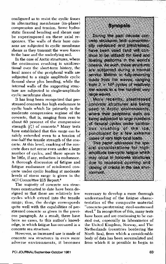
Fig. 4. Wohler curves for prestressing steel.
the loss of effective prestress, and in-creases the load which must be carriedby the steel.
The result, therefore, is that atcracking there is a quantum jump in thestress range of the steel, combined witha smaller but still significant jump inthe maximum compression stress levelin the concrete.
The steels, both unstressed and pre-stressed, have an endurance level ofabout 22,000 psi (160 MPa) or more,although Roper and Hetherington12 re-port values as low as 20,000 psi (140MPa). These levels can only be ap-proached after significant cracking hasoccurred.
For concrete in the splash zone,cracking and spalling, especially thatalong the reinforcing bars, may lead tocorrosion, which in turn, can lead tocorrosion-accelerated fatigue of thesteel.'°" 1, 2° While completely sub-merged structures, even when crackedare essentially free from corrosion, 21 thesplash zone is vulnerable because of
the ready availability of oxygen; hence,special care has to be taken in detailingthese structures.
Stress Range Histories vs.Cumulative Endurance
As long as the concrete remains with-out significant cracking in tension, thenit is possible to plot continuous func-tions3' 20' 22 of stress range versus thelog of the number of cycles (so-calledWohler diagrams). Both the allowablenumber of cycles and probable actualnumber of cycles at each stress rangecan be thus plotted for a typical con-crete offshore platform in the NorthSea. It will be seen (see Fig. 2) that thelatter curve lies well below the allow-able.
Waagaard20 in summarizing the re-sults of earlier research, shows thatMiner sums of 0.2 to 0.5 are appropriatefor describing the cumulative usagecapacity of concrete. When such a
88

y-
a20
w
z
XrnrnWCrHU)
BARS IN BEAMS INCORROSIVE ENVIRONMENT
50 ^\DET NORSKE \^\VERITAS RULES1^. _----
PROBABLE STRESS RANGES INREINFORCING BARS IN TYPICAL NORTHSEA STRUCTURE IN 50 YEARS
LOG N (NUMBER OF CYCLES)
Fig. 5. Wohler curves for conventional reinforcing steel.
X10
Miner's summation is carried out for atypical North Sea structure, it will usu-ally be found to be less than 0.1.
This summation, however, proves tobe very sensitive to the maximum stressrange, the high-amplitude low-cycleend normally contributing a major por-tion of the cumulative usage. This fea-ture can be put into better perspectivewhen the number of cycles is plottedon a natural scale (see Fig. 3). Similarplots can be made for the steels, bothstressed and unstressed (see Figs. 4 and5).
Although conventionally the safetyagainst failure is evaluated parallel tothe abscissa, by comparing the ratio ofthe calculated number of cycles at eachstress range to the corresponding al-lowable number of cycles as shown bythe Wohler curve, and then summingup these ratios, there is another andvery important way to address thesecurves and that is in regard to the ordi-nate, i.e., the stress range itself. A rela-tively modest increase in stress range or
the application of a load factor can leadto a disproportionately high increase inusage (see Fig. 6) 9,20
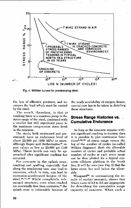
With excursions into the tensile rangeof the concrete, but still without crack-ing, a modified Goodman diagram canbe prepared after the example of Haw-kins (see Fig. 7).22
Once the concrete cracks, however, asignificant jump takes place in the steeland concrete stresses. This jump hasbeen indicated in Figs. 4 and 5 for thegiven steels.
Note also a smaller but significantjump in the probable stress range in theconcrete, which is indicated in Figs. 2and 8. This is due to the dynamic(hammering) effect on crack closing andalso due to stress amplification underdecreasing stiffness.
Cyclic membrane shear can be viewedas a case o.f cyclic diagonal tensionalternating with cyclic diagonal com-pression. When conventionally rein-forced, the concrete will crack undermoderate to large shear forces; hence,
PCI JOURNAUSeptember-October 1981 89

U)
XIii
Z_ 10 -2W(9Q _
IO
w
I-4--j 10
U
0 10J .40 .60
MAX. STRESS RANGE DURING TYPICALLONG-TERM WAVE RESPONSE HISTORY
Fig. 6. Non- linear increase in usage with increasing maximum stressrange.
the steel must be considered to carry allthe shear, and the stress range must bekept low.24 23 Under the typical patternsof diagonal cracking, crack widths areenlarged as compared with cracks nor-mal to the reinforcement at similarlevels of steel stress. Under high inten-sity loadings, displacement along thecracks may produce abrasion of theconcrete surfaces, bending of the steelbars, and rapidly decreasing shear stiff-ness, leading to dynamic amplifications.Conventional orthogonal grid patternsof unstressed steel are very inefficient.Therefore, vertical post-tensioning (seeFig. 9) has proven valuable and practic-able in preventing cracks, or at least, innarrowing their width and changingthem to a vertical direction where theymay be more efficiently resisted by thehorizontal stee1.23
For structures which are destined toserve in the Arctic, and which musttherefore resist the impact and crushingforces of the moving ice, consideration
must be given to the number and mag-nitude of cycles of loading in both flex-ure and shear. Peripheral walls mayhave been subjected to prior flexuraland shear cracking by high concen-trated loads such as those imposed bypressure ridges24 As a result, the rein-forcing steel will subsequently be car-rying most if not all the cyclic tensilestresses which are developed undercontinuous ice crushing.
The use of prestressed tendons, bothin the plane of the peripheral wall, and,in critical zones, through the wall, canbe used to create a favorable state oftriaxial stress, as well as limit thenumber of excursions into the crackingrange, thus preventing fatigue.
Suggested Design Principles
The design of concrete sea structureswhich are subjected to high amplitudecyclic loads, both unidirectional and
90

s5(^ S ^^vy
^SOUZ
d'P ^J^ 60 U) U)
^ ta D 4022f::
20Q
000O 0
TENSION
EXAMPLE: Enter withmaximum compression(minimum stress) at A; proceedto B, C, and D, where readallowable maximum tensilestress.
COMPRESSION=I-2 20
^ Cr A(0(i) 40
2U
60
L 8000
Fig. 7. Modified Goodman diagram for concrete subject to fully reversingstresses; 3 x 10⁶ cycles, 90 percent probability of non -failure, use saturatedstrengths for submerged concrete.
reversing, requires the exercise ofjudgment as well as technical analysis.There is a significant difference inperformance between reinforced andprestressed concrete which is un-cracked, concrete which has been pre-cracked by a prior extreme load, andconcrete which is subject to continuouscrack opening and closing. There is alsoa significant difference fox concretewhich is continually submerged ascompared to that in the splash zone.
Waagaard20 has presented a series offormulas for determining the Wohlercurves for a number of different loadingcombinations and for calculating thecumulative usage. Note that additionalrules are given in Appendix D of theDNV Rules.5
While formulas such as these areperhaps the most precise quantitativeguidelines available to the analyst, theypresent serious problems to the practi-
cal designer because of their complex-ity. Further, these formulas are merelylower bounds of widely scattered em-pirical data and do not reflect the sig-nificant differences in behavior due tosequence of loading, random variationsin stress ranges, and the effect of restperiods.
Therefore, the ACI in their "Guidefor the Design of Fixed Offshore Con-crete Structures" 26 followed thephilosophy originally expressed in theACI Committee 215 report4 and soughtto establish simplified guidelinethreshold values, below which fatigueis assumed to be a non-problem andtherefore requires no further check. Asimilar approach has been applied totwo recent large concrete platforms inthe North Sea.
If these threshold values are ex-ceeded, which usually occurs for only afew members in a structure, then a
PCI JOURNAL/September-October 1981 91
z0NzUI-
t2 MP
+4MP
102 I04 106
LOG Nl08 1010
-30 MPa
-20 M P
\ PROBABLE STRESS\ RANGE FOR 50 YEAR
CRACKED\ LIFESECTION
UNCRACKED '-SECTION ^^
—ALLOWABLESTRESS RANGEFOR CONCRETE
zONU)U
a20C.) -IOMP
PREC0MPRESSION.;:::;s. DUE TO STATIC
LOADS AND PRESTRESS
Fig. 8. Probable versus allowable stress range for prestressed concrete.
more detailed analysis must be carriedout, following procedures such as thoseprescribed by Waagaard.2o
Some suggested threshold values areas follows:
1. Maximum flexural tensile stressless than 100 psi (0.7 MPa) (see Item 7).
2. No tensile membrane stress (seeItem 7).
3. The stress range in the concretedoes not exceed 0.40 f f for environ-mental forces having a monthly returnperiod. This can also be expressed, inthe case of a wave loading, as environ-
mental forces equal to 0.6 times thoseunder extreme conditions.
A more exact limit, applicable espe-cially to cases where high prestress isused, can be given as (0.40 f f – 0.5 o-min), where "v min" is the minimumstress level during a cycle.
4. Stress range in the reinforcementless than 20,000 psi (140 MPa) for thesame environmental loading as in Item3 above. For bent or welded bars, thelimit reduces to 10,000 psi (70 MPa).More exact values are given as (140MPa – 0.33 s min), where "s min" is the
92

CP ^i 'Y C 444I I I I
j I I i I AI I I —VERTICAL
PRESTRESSINGTENDONS
I I I I I I I I I II I I I j I I I I ^ ^ Ijf-
--^^
I I j I I j I j I I I Ilr3 __111IIn;`';II•
1 I I II
TYPICAL Ili • illPATTERN FOR II^__lI^I
1 I Il_ _ ^+ I
rt
TRANSVERSE II ___ IICONVENTIONAL I II -A
I T REINFORCING IL • III
---L+--±---t--'t"++TBARS Ii
III VIII.I I I I • II
III--- l
II I I I ISECTION A-A
II 1 I i i i
ELEVATION OF SHELL WALL
Fig. 9. Schematic layout of vertical prestressing tendons in walls ofconcrete offshore platforms subject to membrane shear cyclicstress ranges.
minimum stress level during the cycle.5. If the shear force variation is
greater than 25 percent of the totalshear, and the total shear exceeds 50percent of the static shear capacity ofthe concrete including that contributedby axial compression, then all shear isto be carried by the stirrups at the stresslevel determined in Item 4 above.
6. Development lengths for rein-forcement at splices are to be doubled(as compared with static requirements)in the regions subject to significant
cyclic loading and especially wherestress reversals occur.
7. For prestressed concrete memberssubject to fully reversing cyclic load-ings, with occasional excursions intothe tensile range of the concrete greaterthan zero in membrane tension or 100psi (0.7 MPa) in flexure, the steel areashould be proportioned so as to be ableto carry the tensile force capacity of theuncracked concrete, at a stress range inthe steel appropriate to the number ofcycles into tension.
PCI JOURNALJSeptember-October 1981 93

The number of cycles in the tensilerange that may occur during the struc-ture's service life may be determinedfrom the projected environmentalloading history, as transformed to stressranges, with consideration of loss ofprestress through time due to stress re-laxation and creep; the latter beingamplified due to the cyclic nature of theloadings.'8
From Figs. 3 and 4, the allowablestress level for the steel can be deter-mined.
The actual cracking level of the con-crete should be reduced from the statictensile strength due to submergence. A
value of 80 percent of the static tensilestrength of the concrete is often appro-priate.
The required steel area can then bedetermined. In the case of cyclic fullyreversing essentially axial stresses, as inthe deck and bottom of a floating plat-form, or in the walls of shafts of offshorestructures, this required steel area per-centage will be the ratio of the allow-able tensile stresses in the concrete andsteel. A relatively high percentage, ap-proaching 2 percent, will usually befound required, which can be contrib-uted by both the stressed and un-stressed steels.
SUMMARY AND CONCLUSIONS
1. Prestressed concrete offshorestructures, both fixed and floating, haveinherently great endurance for moder-ate amplitude high cycle loadings typi-cal of normal sea states.
2. Under extreme high amplitudestress cycles, the concrete structuremay degrade, resulting in acceleratedcreep, loss of bond, decrease in stiff-ness, increased dynamic amplification,increase in Poisson's ratio, loss of pre-stress, and therefore cracking.
3. When the concrete is subjected tohigh amplitude stress ranges, extendingrepeatedly into the cracking range,fatigue can occur in a relatively smallnumber of cycles. The steel stressranges jump significantly upon crack-ing, and may lead to fatigue of the steel.At the high compression end, the in-creased lateral strains may lead to dis-ruption of bond between paste andaggregate and failure of the concrete incompression.
4. Confinement of the concrete bothstiffens and contains this lateral expan-sion and increases the resistance of theconcrete to compressive fatigue.
5. Use of adequate steel percentages,
both unstressed and stressed, controlsthe jump in steel stress range and canbe an effective means of preventingfatigue of the steel after cracking.
6. For concrete which is submerged,local hydraulic fracturing may occurwith repeated opening and closing ofthe cracks. Hence, opening and closingof cracks in submerged concrete shouldbe limited to a relatively few cyclesduring a service lifetime.
7. Cyclic membrane shear can mosteffectively be resisted by verticalpost-tensioning combined with hori-zontal steel (stressed or unstressed).
8. Special care must be given in criti-cal zones, to proper detailing and soundconstruction practice in order to ensurethat construction joints will not act aspreformed cracks and to eliminate localstress raisers such as sharp reentrantcorners, embedments, etc., that willlead to early cracking. Where thesecannot be avoided, additional localreinforcement should be provided toprevent crack propagation.
9. The splash zone is particularlyvulnerable because of the possibility ofcorrosion-accelerated fatigue after sig-
94

nificant cracking of the concrete. Thiscracking should be severely limited byproper design (prestress, adequate steelpercentages, and confinement).
10. Adequate endurance against lossof bond can be provided in zones sub-ject to significant stress reversals (suchas the base of shafts) by using reducedbond stresses (e.g., doubling the de-velopment length as compared withthat required for static loading).
11. In evaluating safety againstfatigue, attention should be given to theeffect of a possible increase in thestress ranges at the low-cycle high-amplitude end.
12. Through proper design and con-struction, prestressed concrete seastructures can be assured of long lifeeven under the cyclic loadings accom-panying the most severe environmentalconditions.
REFERENCES
1. Blenkarn, K. A., "Measurement andAnalysis of Ice Forces. on Cook InletStructures," OTC 1261, OffshoreTechnology Conference, Houston,Texas, 1970.
2. Hibler, W. D., "Characterization ofCold-Regions Terrain Using AirborneLaser - Profilometry," Journal ofGlaciology, V. 15, No. 73, 1975.
3. Gerwick, B. C., and Venuti, W. J.,"High- and Low-Cycle Fatigue Be-havior of Prestressed Concrete inOffshore Structures," Journal of EnergyResources Technology, V. 102, March1980, pp. 18-23.
4. ACI Committee 215, "Considerations forDesign of Concrete Structures Subjectedto Fatigue Loading," ACI Journal, Pro-ceedings V. 71, No. 3, March 1974, pp.97-121.
5. "Symposium on the Application of Pre-stressed Concrete to Machinery Struc-tures, Proceedings, Federation Inter-nationale de la Precontrainte, January1964.
6. Gerwick, B. C., and Brauner, H. A.,"Design of High-Performance Pre-stressed Concrete Piles for DynamicLoading," Special Technical Publication670, American Society for Testing andMaterials, Philadelphia, 1979.
7. White, R. N., and Gergely, P., "DesignConsiderations for Seismic TangentialShear in. Reinforced Concrete Contain-ment Structures," Proceedings, FourthInternational Conference on StructuralMechanics in Reactor Technology, 1977.
8. Waagaard, K., "Fatigue of Offshore Con-crete Structures-Design and Experi-
mental Investigation," Paper OTC 3009,Presented at Ninth Annual OffshoreTechnology Conference, May 1977.
9. Taylor, H., and Sharp, J., "Fatigue inOffshore Concrete Structures," TheStructural Engineer, March 1978.
10. Bannister, J. L., "Fatigue Resistance ofReinforcement for Concrete," Proceed-ings, Underwater ConstructionTechnology Conference, UniversityCollege, Cardiff, Wales, 1975.
11. Arthur, P. D., Earl, J. C., Hodykiess, T.,"Corrosion Fatigue in Concrete forMarine Applications," Paper presentedat ACI Fall Convention, Puerto Rico,1980.
12. Roper, H., and Hetherington, G. B.,"Fatigue of Reinforced Concrete in Air,Chloride Solution, and Sea Water,"Paper presented at ACI Annual Con-vention, Dallas, Texas 1981.
13. Muguruma, H., "Study on Low-CycleFatigue Strength of Post-Tensioned Un-bonded Prestressed Concrete Beams,"Journal of the Japan Prestressed Con-crete Engineering Association, V. 20,1978.
14. Rabbat, B. G.; Kaar, P. H.; Russell, H.G.; and Bruce, R. N., "Fatigue Tests ofFull-Size Prestressed Girders," Techni-cal Report 113, State of Louisiana De-partment of Transportation and De-velopment; Portland Cement Associa-tion, June 1978. See also "Fatigue Testsof Pretensioned Girders With Blanketedand Draped Strands" by same authors inJuly-August PCI JOURNAL, V. 24, No.4, 1979, pp. 88-114.
15. Balachandra, M.; Bagge, C.; and
PCI JOURNAUSeptember-October 1981 95
Haynes, H., "Low Cycle Fatigue Testsof Hollow Concrete Spheres," AgbabianAssociates, Defense Nuclear Agency,Washington, D.C., April 1978 (distribu-tion limited).
16 Hawkins, N. M., "Fatigue Consid-erations for Concrete Ships andOffshore Structures," Proceedings,Conference on Concrete Ships andFloating Structures, University ofCalifornia Extension Division, Ber-keley, California, 1975.
17 T.N.O., "Fatigue of Concrete," ReportNo. 04. 2. 6014; Institute T.N.O., Delft,The Netherlands, December 2, 1977.
18. Balaguru, P. N., "Analysis of PrestressedConcrete Beams for Fatigue Loading,"PCI JOURNAL, V. 26, No. 3, May-June1981, pp. 70-94.
19. Goto, Y., "Cracks Found in ConcreteAround Deformed Reinforcing Bars,"ACI Journal, V. 68, No. 4, April 1971,pp. 244-251.
20. Waagaard, K., "Fatigue Strength Evalu-ation of Offshore Concrete Structures,"Paper presented at ACI Annual Con-vention, Dallas, Texas, February 1981.
21. Beeby, A. W., "Corrosion of Reinforcing
Steel in Concrete and its Relation toCracking," The Structural Engineer,March 1978.
22. Hawkins, N. M., "Fatigue Characteris-tics in Bond and Shear of ReinforcedConcrete Beams, SP-41, Fatigue ofConcrete, American Concrete Institute,1974.
23. Gerwick, B. C., Jr., "Cyclic ShearCapacity of Offshore Concrete Struc-tures," International Symposium ofOffshore Structures, Brazil Offshore'79 RILEM-FIP-CEB-CNPq-PETRO-BRAS-UFRJ, Rio de Janeiro, Brazil,October, 1979.
24. Gerwick, B. C., Jr.; Litton, R. W.; Rei-mer, R. B., "Resistance of ConcreteWalls to High Concentrated Ice Loads,"Offshore Technology Conference Pre-prints, OTC 4111, 1981.
25. Det Norske Veritas, "Rules for the De-sign, Construction and Inspection ofOffshore Structures," Appendix D, Con-crete Structures, Det Norske Veritas,Oslo, Norway, 1977.
26. ACI Committee 357, "Guide for the De-sign of Fixed Offshore Concrete Struc-tures," ACI Journal, V. 75, No. 12, De-cember 1978, pp. 684-709.
NOTE: Discussion of this paper is invited. Please submit yourdiscussion to PCI Headquarters by May 1, 1982.
96