HGB-609-A FLUID REGULATOR - carlisleft.com · Appl L octite 271 to the threa and assemble Item 10...
8
SB-6-379-A (8/2017) 1 / 8 www.carlisleft.com HGB-609-A FLUID REGULATOR EN SERVICE MANUAL IMPORTANT! DO NOT DESTROY It is the Customer's responsibility to have all operators and service personnel read and understand this manual. Contact your local DeVilbiss representative for additional copies of this manual. READ ALL INSTRUCTIONS BEFORE OPERATING THIS DEVILBISS PRODUCT.
Transcript of HGB-609-A FLUID REGULATOR - carlisleft.com · Appl L octite 271 to the threa and assemble Item 10...
SB-6-379-A (8/2017) 1 / 8 www.carlisleft.com
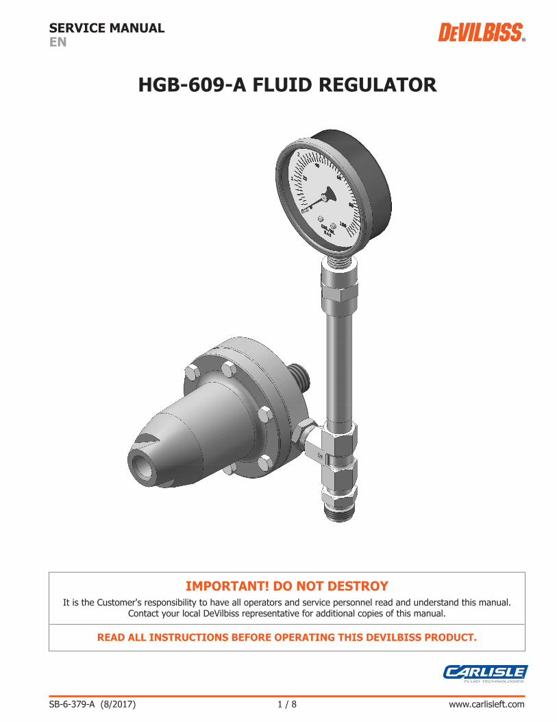
HGB-609-A FLUID REGULATOR
ENSERVICE MANUAL
IMPORTANT! DO NOT DESTROYIt is the Customer's responsibility to have all operators and service personnel read and understand this manual.
Contact your local DeVilbiss representative for additional copies of this manual.
READ ALL INSTRUCTIONS BEFORE OPERATING THIS DEVILBISS PRODUCT.
SB-6-379-A (8/2017)2 / 8
EN
www.carlisleft.com
DeVilbiss reserves the right to modify equipment specification without prior notice.
LOCK OUT / TAG-OUTFailure to de-energize, disconnect, lock out and tag-out all power sources before performing equipment maintenance could cause serious injury or death.
OPERATOR TRAINING All personnel must be trained before operating finishing equipment.
EQUIPMENT MISUSE HAZARD Equipment misuse can cause the equipment to rupture, malfunction, or start unexpectedly and result in serious injury.
PROJECTILE HAZARDYou may be injured by venting liquids or gases that are released under pressure, or flying debris.
PINCH POINT HAZARD Moving parts can crush and cut. Pinch points are basically any areas where there are moving parts.
INSPECT THE EQUIPMENT DAILY Inspect the equipment for worn or broken parts on a daily basis. Do not operate the equipment if you are uncertain about its condition.
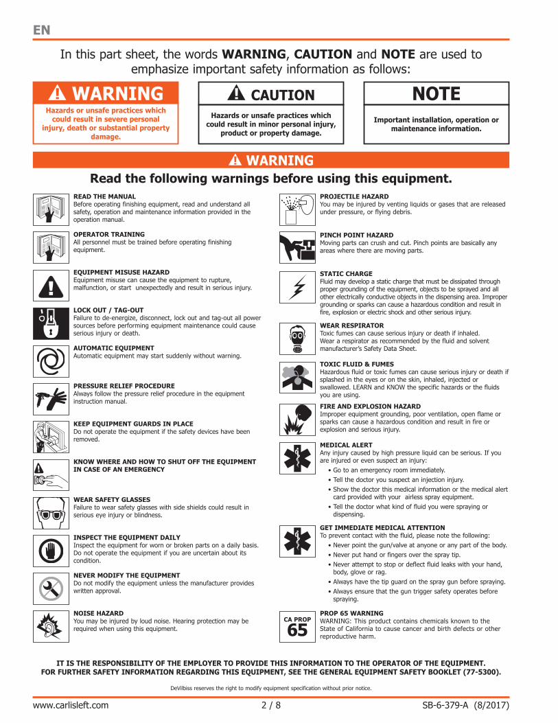
In this part sheet, the words WARNING, CAUTION and NOTE are used to emphasize important safety information as follows:
Hazards or unsafe practices which could result in minor personal injury,
product or property damage.
! CAUTIONImportant installation, operation or
maintenance information.
NOTE
Read the following warnings before using this equipment.READ THE MANUAL Before operating finishing equipment, read and understand all safety, operation and maintenance information provided in the operation manual.
WEAR SAFETY GLASSES Failure to wear safety glasses with side shields could result in serious eye injury or blindness.
NEVER MODIFY THE EQUIPMENT Do not modify the equipment unless the manufacturer provides written approval.
IT IS THE RESPONSIBILITY OF THE EMPLOYER TO PROVIDE THIS INFORMATION TO THE OPERATOR OF THE EQUIPMENT.FOR FURTHER SAFETY INFORMATION REGARDING THIS EQUIPMENT, SEE THE GENERAL EQUIPMENT SAFETY BOOKLET (77-5300).
KNOW WHERE AND HOW TO SHUT OFF THE EQUIPMENT IN CASE OF AN EMERGENCY
PRESSURE RELIEF PROCEDURE Always follow the pressure relief procedure in the equipment instruction manual.
NOISE HAZARD You may be injured by loud noise. Hearing protection may be required when using this equipment.
STATIC CHARGE Fluid may develop a static charge that must be dissipated through proper grounding of the equipment, objects to be sprayed and all other electrically conductive objects in the dispensing area. Improper grounding or sparks can cause a hazardous condition and result in fire, explosion or electric shock and other serious injury.
PROP 65 WARNINGWARNING: This product contains chemicals known to the State of California to cause cancer and birth defects or other reproductive harm.
WEAR RESPIRATOR Toxic fumes can cause serious injury or death if inhaled. Wear a respirator as recommended by the fluid and solvent manufacturer’s Safety Data Sheet.
TOXIC FLUID & FUMES Hazardous fluid or toxic fumes can cause serious injury or death if splashed in the eyes or on the skin, inhaled, injected or swallowed. LEARN and KNOW the specific hazards or the fluids you are using.
KEEP EQUIPMENT GUARDS IN PLACE Do not operate the equipment if the safety devices have been removed.
! WARNING
AUTOMATIC EQUIPMENTAutomatic equipment may start suddenly without warning.
FIRE AND EXPLOSION HAZARD Improper equipment grounding, poor ventilation, open flame or sparks can cause a hazardous condition and result in fire or explosion and serious injury.
MEDICAL ALERT Any injury caused by high pressure liquid can be serious. If you are injured or even suspect an injury:
• Go to an emergency room immediately.• Tell the doctor you suspect an injection injury.• Show the doctor this medical information or the medical alert
card provided with your airless spray equipment.• Tell the doctor what kind of fluid you were spraying or
dispensing.
GET IMMEDIATE MEDICAL ATTENTION To prevent contact with the fluid, please note the following:
• Never point the gun/valve at anyone or any part of the body.• Never put hand or fingers over the spray tip.• Never attempt to stop or deflect fluid leaks with your hand,
body, glove or rag.• Always have the tip guard on the spray gun before spraying.• Always ensure that the gun trigger safety operates before
spraying.
Hazards or unsafe practices which could result in severe personal
injury, death or substantial property damage.
! WARNING
SB-6-379-A (8/2017) 3 / 8
EN
www.carlisleft.com
Do not use with fluids hotter than 130 degrees Fahrenheit. Not suitable for concentrated acids or bases.
! WARNING
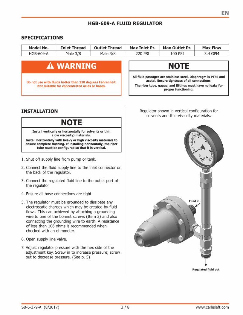
Regulated fluid out
Fluid in
Regulator shown in vertical configuration for solvents and thin viscosity materials.
INSTALLATION
Install vertically or horizontally for solvents or thin (low viscosity) materials.
Install horizontally with heavy or high viscosity materials to ensure complete flushing. If installing horizontally, the riser
tube must be configured so that it is vertical.
NOTE
1. Shut off supply line from pump or tank.
2. Connect the fluid supply line to the inlet connector on the back of the regulator.
3. Connect the regulated fluid line to the outlet port of the regulator.
4. Ensure all hose connections are tight.
5. The regulator must be grounded to dissipate any electrostatic charges which may be created by fluid flows. This can achieved by attaching a grounding wire to one of the bonnet screws (Item 3) and also connecting the grounding wire to earth. A resistance of less than 106 ohms is recommended when checked with an ohmmeter.
6. Open supply line valve.
7. Adjust regulator pressure with the hex side of the adjustment key. Screw in to increase pressure; screw out to decrease pressure. (See p. 5)
All fluid passages are stainless steel. Diaphragm is PTFE and acetal. Ensure tightness of all connections.
The riser tube, gauge, and fittings must have no leaks for proper functioning.
NOTE
SPECIFICATIONS
Model No. Inlet Thread Outlet Thread Max Inlet Pr. Max Outlet Pr. Max FlowHGB-609-A Male 3/8 Male 3/8 220 PSI 100 PSI 3.4 GPM
HGB-609-A FLUID REGULATOR
SB-6-379-A (8/2017)4 / 8
EN
www.carlisleft.com
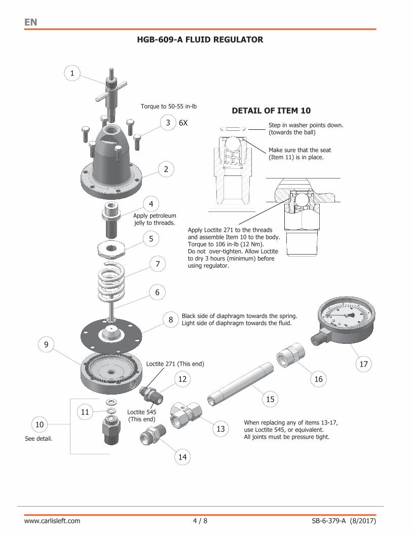
Torque to 50-55 in-lb
Apply petroleum jelly to threads.
Black side of diaphragm towards the spring. Light side of diaphragm towards the fluid.
When replacing any of items 13-17, use Loctite 545, or equivalent. All joints must be pressure tight.
Step in washer points down. (towards the ball)
Make sure that the seat (Item 11) is in place.
Loctite 545 (This end)
Loctite 271 (This end)
See detail.
DETAIL OF ITEM 10
Apply Loctite 271 to the threads and assemble Item 10 to the body. Torque to 106 in-lb (12 Nm). Do not over-tighten. Allow Loctite to dry 3 hours (minimum) before using regulator.
1
3 6X
2
4
5
7
8
6
9
12
13
14
15
16
17
10
11
Third Angle Projection
SHEET:
THIS DRAWING IS THE PROPERTY OF CARLISLE FLUID TECHNOLOGIES.INFORMATION, INCLUDING THE PRINCIPLE OF DESIGN, CONTAINED IN THIS DRAWING IS CONFIDENTIAL AND IS NOT TO BE COPIED, REPRODUCED, LOANED, OR USED IN ANY MANNER THAT MAY CONSTITUTE DETRIMENT DIRECTLY OR INDIRECTLY TO CARLISLE FLUID TECHNOLOGIES. ACCEPTANCE OF THIS DRAWING WILL BE CONSTRUED AS AN AGREEMENT TO THE ABOVE.
IMPORTANT NOTES:DIMENSIONS AND FINISHES APPLY AFTER PLATING OR HEAT TREATMENT. THREADS MUST FIT GAUGE. FILLETS TO BE .4/.5mm [.015/.020in] MAX. BREAK ALL SHARP CORNERS, .4/.5mm [.015/.020in] MAX. REMOVE ALL BURRS. DO NOT USE ANY SILICONE BASED MATERIALS OR PRODUCTS IN THE MANUFACTURING, PACKAGING, AND SHIPPING PROCESS.
DRAWN BY:
SIZE:
3/5/17 DMATERIAL: FINISH:
FLUID REGULATOR
APPROVED DATE:
APPROVED BY:SCALE:
1 of 1PART No:
DESCRIPTION:
DRAWN DATE:
PDB PDB
3/5/17
1:1REV:
320 Phillips Ave. Toledo, OH 43612 © 2016
HGB-609-A-SM A
CARLISLE FLUID TECHNOLOGIESUNLESS OTHERWISE SPECIFIED:ALL DIMENSIONS ARE IN INCHES
TOLERANCES:TWO PLACE DECIMAL: µ.010
THREE PLACE DECIMAL: µ.005FRACTION: 1/64
ANGLE: µ1°CONCENTRICITY: .006 TIR
SURFACE FINISH: 63 microinches
HGB-609-A FLUID REGULATOR
SB-6-379-A (8/2017) 5 / 8
EN
www.carlisleft.com
HGB-609-A FLUID REGULATOR
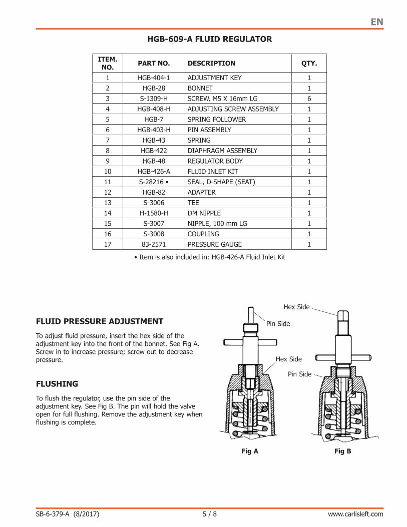
FLUID PRESSURE ADJUSTMENT
To adjust fluid pressure, insert the hex side of the adjustment key into the front of the bonnet. See Fig A. Screw in to increase pressure; screw out to decrease pressure.
FLUSHING
To flush the regulator, use the pin side of the adjustment key. See Fig B. The pin will hold the valve open for full flushing. Remove the adjustment key when flushing is complete.
Fig A Fig B
Hex Side
Pin Side
Hex Side
Pin Side
ITEM. NO. PART NO. DESCRIPTION QTY.
1 HGB-404-1 ADJUSTMENT KEY 1
2 HGB-28 BONNET 1
3 S-1309-H SCREW, M5 X 16mm LG 6
4 HGB-408-H ADJUSTING SCREW ASSEMBLY 1
5 HGB-7 SPRING FOLLOWER 1
6 HGB-403-H PIN ASSEMBLY 1
7 HGB-43 SPRING 1
8 HGB-422 DIAPHRAGM ASSEMBLY 1
9 HGB-48 REGULATOR BODY 1
10 HGB-426-A FLUID INLET KIT 1
11 S-28216 • SEAL, D-SHAPE (SEAT) 1
12 HGB-82 ADAPTER 1
13 S-3006 TEE 1
14 H-1580-H DM NIPPLE 1
15 S-3007 NIPPLE, 100 mm LG 1
16 S-3008 COUPLING 1
17 83-2571 PRESSURE GAUGE 1
• Item is also included in: HGB-426-A Fluid Inlet Kit
SB-6-379-A (8/2017)6 / 8
EN
www.carlisleft.com
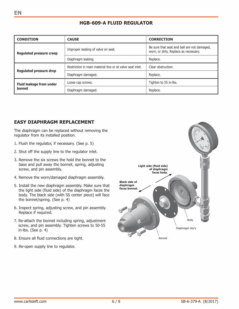
Black side of diaphragm faces bonnet.
Light side (fluid side) of diaphragm
faces body.
Body
Diaphragm Ass’y
Bonnet
HGB-609-A FLUID REGULATOR
EASY DIAPHRAGM REPLACEMENT
The diaphragm can be replaced without removing the regulator from its installed position.
1. Flush the regulator, if necessary. (See p. 5)
2. Shut off the supply line to the regulator inlet.
3. Remove the six screws the hold the bonnet to the base and pull away the bonnet, spring, adjusting screw, and pin assembly.
4. Remove the worn/damaged diaphragm assembly.
5. Install the new diaphragm assembly. Make sure that the light side (fluid side) of the diaphragm faces the body. The black side (with SS center piece) will face the bonnet/spring. (See p. 4)
6. Inspect spring, adjusting screw, and pin assembly. Replace if required.
7. Re-attach the bonnet including spring, adjustment screw, and pin assembly. Tighten screws to 50-55 in-lbs. (See p. 4)
8. Ensure all fluid connections are tight.
9. Re-open supply line to regulator.
CONDITION CAUSE CORRECTION
Regulated pressure creepImproper seating of valve on seat. Be sure that seat and ball are not damaged,
worn, or dirty. Replace as necessary.
Diaphragm leaking. Replace.
Regulated pressure dropRestriction in main material line or at valve seat inlet. Clear obstruction.
Diaphragm damaged. Replace.
Fluid leakage from under bonnet
Loose cap screws. Tighten to 55 in-lbs.
Diaphragm damaged. Replace.

SB-6-379-A (8/2017) 7 / 8
EN
www.carlisleft.com
NOTES

SB-6-379-A (8/2017)8 / 8
EN
www.carlisleft.com
WARRANTY POLICY
DeVilbiss products are covered by Carlisle Fluid Technologies one year materials and workmanship limited warranty. The use of any parts or accessories, from a source other than
Carlisle Fluid Technologies, will void all warranties. For specific warranty information please contact the closest Carlisle Fluid Technologies location listed below.
DeVilbiss is part of Carlisle Fluid Technologies, a global leader in innovative finishing technologies. For technical assistance or to locate an authorized distributor, contact one of our international sales
and customer support locations.
USA/Canada [email protected] Tel: 1-888-992-4657 Fax: 1-888-246-5732
United Kingdom [email protected] Tel: +44 (0)1202 571 111 Fax: +44 (0)1202 573 488
China [email protected] Tel: +8621-3373 0108 Fax: +8621-3373 0308
Mexico [email protected] Tel: +52 55 5321 2300 Fax: +52 55 5310 4790
Japan [email protected] Tel: +81 45 785 6421 Fax: +81 45 785 6517
Brazil [email protected] Tel: +55 11 5641 2776 Fax: +55 11 5641 1256
Germany [email protected] Tel: +49 (0) 6074 403 1 Fax: +49 (0) 6074 403 281
Australia [email protected] Tel: +61 (0) 2 8525 7555 Fax: +61 (0) 2 8525 7575
Carlisle Fluid Technologies reserves the right to modify equipment specifications without prior notice. DeVilbiss®, Ransburg®, ms®, BGK®, and Binks® are registered trademarks of Carlisle Fluid Technologies, Inc.
©2017 Carlisle Fluid Technologies, Inc. All rights reserved.
For the latest information about our products, visit www.carlisleft.com.