
HFODD for Leadership Class Computers N. Schunck, J. McDonnell, Hai Ah Nam.

HFODD
(v2.40h)
User’s Guide


HFODD (v2.40h): User’s Guide.
J. Dobaczewski,a,b,1 B.G. Carlsson,b J. Dudek,c J. Engel,d P. Olbratowski,a P.Powa lowski,e M. Sadziak,e J. Sarich,f W. Satu la,a N. Schunck,g,h A.
Staszczak,g,h,i M. Stoitsov,g,h,j M. Zalewskia and H. Zdunczuka
aInstitute of Theoretical Physics, University of Warsaw ul. Hoza 69, PL-00681 Warsaw,Poland
bDepartment of Physics, P.O. Box 35 (YFL), FI-40014 University of Jyvaskyla, FinlandcInstitut Pluridisciplinaire Hubert Curien (IPHC-DRS) et Universite Louis Pasteur/CNRS,
F-67037 Strasbourg Cedex 2, FrancedDepartment of Physics and Astronomy, CB3255, University of North Carolina,
Chapel Hill, NC 27599-3255, USAeDepartment of Physics, University of Warsaw, ul. Hoza 69, 00-681, Warsaw, Poland
f Argonne National Laboratory, 9700 South Cass Avenue, Building 221,Argonne, IL 60439-4844, USA
gDepartment of Physics and Astronomy, University of Tennessee, Knoxville, TN 37996, USAhOak Ridge National Laboratory, P.O. Box 2008, Oak Ridge, TN 37831, USA
iDepartment of Theoretical Physics, Maria Curie-Sk lodowska University,pl. M. Curie-Sk lodowskiej 1, 20-031 Lublin, PolandjInstitute of Nuclear Research and Nuclear Energy,
Bulgarian Academy of Sciences, Sofia, Bulgaria
Abstract
We describe the input data and installation procedures of the code hfodd (v2.40h). Thepresent write-up contains complete and comprehensive information that has originally beengiven in six independent publications. It is enhanced by the subject index and indexes ofvariables, input-data keywords, subroutines, and files that are used in this user guide.
Keywords
Hartree-Fock; Hartree-Fock-Bogolyubov; Skyrme interaction; self-consistent mean field; nuclearmany-body problem; superdeformation; quadrupole deformation; octupole deformation; pair-ing; nuclear radii; single-particle spectra; nuclear rotation; high-spin states; three-dimensionalrotation; chiral symmetry in nuclei; gauge symmetry; moments of inertia; level crossings; har-monic oscillator; Coulomb field; pairing; point-group symmetries. Yukawa interaction; angular-momentum projection; generator coordinate method; Schiff moments
1E-mail: [email protected]
1

2 Contents
Contents
1. INTRODUCTION 7
2. INPUT DATA FILE 82.1. General data . . . . . . . . . . . . . . . . . . . . . . . . . . . . . . . . . . . . . 10
2.1.1. Keyword: NUCLIDE . . . . . . . . . . . . . . . . . . . . . . . . . . . . . 102.1.2. Keyword: ITERATIONS . . . . . . . . . . . . . . . . . . . . . . . . . . . 102.1.3. Keyword: ITERAT EPS . . . . . . . . . . . . . . . . . . . . . . . . . . . . 102.1.4. Keyword: MAXANTIOSC . . . . . . . . . . . . . . . . . . . . . . . . . . . 102.1.5. Keyword: PING-PONG . . . . . . . . . . . . . . . . . . . . . . . . . . . . 112.1.6. Keyword: CHAOTIC . . . . . . . . . . . . . . . . . . . . . . . . . . . . . 122.1.7. Keyword: PHASESPACE . . . . . . . . . . . . . . . . . . . . . . . . . . . 12
2.2. Interaction . . . . . . . . . . . . . . . . . . . . . . . . . . . . . . . . . . . . . . . 142.2.1. Keyword: SKYRME-SET . . . . . . . . . . . . . . . . . . . . . . . . . . . 142.2.2. Keyword: SKYRME-STD . . . . . . . . . . . . . . . . . . . . . . . . . . . 142.2.3. Keyword: HBAR2OVR2M . . . . . . . . . . . . . . . . . . . . . . . . . . . 152.2.4. Keyword: SPIN ORBIT . . . . . . . . . . . . . . . . . . . . . . . . . . . . 152.2.5. Keyword: LANDAU . . . . . . . . . . . . . . . . . . . . . . . . . . . . . . 152.2.6. Keyword: LANDAU-SAT . . . . . . . . . . . . . . . . . . . . . . . . . . . 162.2.7. Keyword: EVE SCA TS . . . . . . . . . . . . . . . . . . . . . . . . . . . . 162.2.8. Keyword: ODD SCA TS . . . . . . . . . . . . . . . . . . . . . . . . . . . . 172.2.9. Keyword: EVE SCA PM . . . . . . . . . . . . . . . . . . . . . . . . . . . . 172.2.10. Keyword: ODD SCA PM . . . . . . . . . . . . . . . . . . . . . . . . . . . . 182.2.11. Keyword: EVE ADD TS . . . . . . . . . . . . . . . . . . . . . . . . . . . . 182.2.12. Keyword: ODD ADD TS . . . . . . . . . . . . . . . . . . . . . . . . . . . . 182.2.13. Keyword: EVE ADD PM . . . . . . . . . . . . . . . . . . . . . . . . . . . . 182.2.14. Keyword: ODD ADD PM . . . . . . . . . . . . . . . . . . . . . . . . . . . . 192.2.15. Keyword: G SCALING . . . . . . . . . . . . . . . . . . . . . . . . . . . . 192.2.16. Keyword: PAIR MATRI . . . . . . . . . . . . . . . . . . . . . . . . . . . . 192.2.17. Keyword: INI FERMI . . . . . . . . . . . . . . . . . . . . . . . . . . . . 192.2.18. Keyword: INI DELTA . . . . . . . . . . . . . . . . . . . . . . . . . . . . 192.2.19. Keyword: FIXDELTA N . . . . . . . . . . . . . . . . . . . . . . . . . . . . 202.2.20. Keyword: FIXDELTA P . . . . . . . . . . . . . . . . . . . . . . . . . . . . 202.2.21. Keyword: PAIRNFORCE . . . . . . . . . . . . . . . . . . . . . . . . . . . 202.2.22. Keyword: PAIRPFORCE . . . . . . . . . . . . . . . . . . . . . . . . . . . 202.2.23. Keyword: PAIR FORCE . . . . . . . . . . . . . . . . . . . . . . . . . . . . 212.2.24. Keyword: PAIRNINTER . . . . . . . . . . . . . . . . . . . . . . . . . . . 212.2.25. Keyword: PAIRPINTER . . . . . . . . . . . . . . . . . . . . . . . . . . . 212.2.26. Keyword: PAIR INTER . . . . . . . . . . . . . . . . . . . . . . . . . . . . 212.2.27. Keyword: CUTOFF . . . . . . . . . . . . . . . . . . . . . . . . . . . . . . 212.2.28. Keyword: YUKAWATERM . . . . . . . . . . . . . . . . . . . . . . . . . . . 212.2.29. Keyword: COULOMBPAR . . . . . . . . . . . . . . . . . . . . . . . . . . . 222.2.30. Keyword: INSERT HO . . . . . . . . . . . . . . . . . . . . . . . . . . . . 24
2.3. Symmetries . . . . . . . . . . . . . . . . . . . . . . . . . . . . . . . . . . . . . . 25

Contents 3
2.3.1. Keyword: SIMPLEXY . . . . . . . . . . . . . . . . . . . . . . . . . . . . . 252.3.2. Keyword: SIGNATUREY . . . . . . . . . . . . . . . . . . . . . . . . . . . 252.3.3. Keyword: PARITY . . . . . . . . . . . . . . . . . . . . . . . . . . . . . . 252.3.4. Keyword: ROTATION . . . . . . . . . . . . . . . . . . . . . . . . . . . . . 252.3.5. Keyword: TIMEREVERS . . . . . . . . . . . . . . . . . . . . . . . . . . . 272.3.6. Keyword: TSIMPLEX Y . . . . . . . . . . . . . . . . . . . . . . . . . . . . 272.3.7. Keyword: TSIMPLEXES . . . . . . . . . . . . . . . . . . . . . . . . . . . 272.3.8. Keyword: TSIMPLEX3D . . . . . . . . . . . . . . . . . . . . . . . . . . . 272.3.9. Keyword: PAIRING . . . . . . . . . . . . . . . . . . . . . . . . . . . . . 272.3.10. Keyword: HFB . . . . . . . . . . . . . . . . . . . . . . . . . . . . . . . . 282.3.11. Keyword: BCS . . . . . . . . . . . . . . . . . . . . . . . . . . . . . . . . 282.3.12. Keyword: FILSIG NEU . . . . . . . . . . . . . . . . . . . . . . . . . . . . 282.3.13. Keyword: FILSIG PRO . . . . . . . . . . . . . . . . . . . . . . . . . . . . 292.3.14. Keyword: INI INVERS . . . . . . . . . . . . . . . . . . . . . . . . . . . . 292.3.15. Keyword: INI ROTAT . . . . . . . . . . . . . . . . . . . . . . . . . . . . 292.3.16. Keyword: PROJECTGCM . . . . . . . . . . . . . . . . . . . . . . . . . . . 302.3.17. Keyword: SAVEKERNEL . . . . . . . . . . . . . . . . . . . . . . . . . . . 302.3.18. Keyword: CHECKERNEL . . . . . . . . . . . . . . . . . . . . . . . . . . . 312.3.19. Keyword: PARAKERNEL . . . . . . . . . . . . . . . . . . . . . . . . . . . 312.3.20. Keyword: TRANSITION . . . . . . . . . . . . . . . . . . . . . . . . . . . 312.3.21. Keyword: CUTOVERLAP . . . . . . . . . . . . . . . . . . . . . . . . . . . 322.3.22. Keyword: LIPKIN . . . . . . . . . . . . . . . . . . . . . . . . . . . . . . 322.3.23. Keyword: INI LIPKIN . . . . . . . . . . . . . . . . . . . . . . . . . . . . 322.3.24. Keyword: FIXLAMB2 N . . . . . . . . . . . . . . . . . . . . . . . . . . . . 322.3.25. Keyword: FIXLAMB2 P . . . . . . . . . . . . . . . . . . . . . . . . . . . . 322.3.26. Keyword: SLOWLIPKIN . . . . . . . . . . . . . . . . . . . . . . . . . . . 332.3.27. Keyword: FIXFERMI N . . . . . . . . . . . . . . . . . . . . . . . . . . . . 332.3.28. Keyword: FIXFERMI P . . . . . . . . . . . . . . . . . . . . . . . . . . . . 33
2.4. Configurations with no conserved symmetries . . . . . . . . . . . . . . . . . . . 342.4.1. Keyword: PHNONE NEU . . . . . . . . . . . . . . . . . . . . . . . . . . . . 342.4.2. Keyword: PHNONE PRO . . . . . . . . . . . . . . . . . . . . . . . . . . . . 342.4.3. Keyword: DIANON NEU . . . . . . . . . . . . . . . . . . . . . . . . . . . . 342.4.4. Keyword: DIANON PRO . . . . . . . . . . . . . . . . . . . . . . . . . . . . 342.4.5. Keyword: BLOCKSIZ N . . . . . . . . . . . . . . . . . . . . . . . . . . . . 342.4.6. Keyword: BLOCKSIZ P . . . . . . . . . . . . . . . . . . . . . . . . . . . . 35
2.5. Configurations with conserved simplex . . . . . . . . . . . . . . . . . . . . . . . 362.5.1. Keyword: VACSIM NEU . . . . . . . . . . . . . . . . . . . . . . . . . . . . 362.5.2. Keyword: VACSIM PRO . . . . . . . . . . . . . . . . . . . . . . . . . . . . 362.5.3. Keyword: PHSIMP NEU . . . . . . . . . . . . . . . . . . . . . . . . . . . . 362.5.4. Keyword: PHSIMP PRO . . . . . . . . . . . . . . . . . . . . . . . . . . . . 362.5.5. Keyword: DIASIM NEU . . . . . . . . . . . . . . . . . . . . . . . . . . . . 372.5.6. Keyword: DIASIM PRO . . . . . . . . . . . . . . . . . . . . . . . . . . . . 372.5.7. Keyword: BLOCKSIM N . . . . . . . . . . . . . . . . . . . . . . . . . . . . 372.5.8. Keyword: BLOCKSIM P . . . . . . . . . . . . . . . . . . . . . . . . . . . . 37
2.6. Configurations with conserved parity . . . . . . . . . . . . . . . . . . . . . . . . 38

4 Contents
2.6.1. Keyword: VACPAR NEU . . . . . . . . . . . . . . . . . . . . . . . . . . . . 382.6.2. Keyword: VACPAR PRO . . . . . . . . . . . . . . . . . . . . . . . . . . . . 382.6.3. Keyword: PHPARI NEU . . . . . . . . . . . . . . . . . . . . . . . . . . . . 382.6.4. Keyword: PHPARI PRO . . . . . . . . . . . . . . . . . . . . . . . . . . . . 382.6.5. Keyword: DIAPAR NEU . . . . . . . . . . . . . . . . . . . . . . . . . . . . 392.6.6. Keyword: DIAPAR PRO . . . . . . . . . . . . . . . . . . . . . . . . . . . . 402.6.7. Keyword: BLOCKSIQ N . . . . . . . . . . . . . . . . . . . . . . . . . . . . 402.6.8. Keyword: BLOCKSIQ P . . . . . . . . . . . . . . . . . . . . . . . . . . . . 40
2.7. Configurations with conserved parity and signature . . . . . . . . . . . . . . . . 412.7.1. Keyword: VACSIG NEU . . . . . . . . . . . . . . . . . . . . . . . . . . . . 412.7.2. Keyword: VACSIG PRO . . . . . . . . . . . . . . . . . . . . . . . . . . . . 412.7.3. Keyword: PHSIGN NEU . . . . . . . . . . . . . . . . . . . . . . . . . . . . 412.7.4. Keyword: PHSIGN PRO . . . . . . . . . . . . . . . . . . . . . . . . . . . . 422.7.5. Keyword: DIASIG NEU . . . . . . . . . . . . . . . . . . . . . . . . . . . . 422.7.6. Keyword: DIASIG PRO . . . . . . . . . . . . . . . . . . . . . . . . . . . . 422.7.7. Keyword: BLOCKSIG N . . . . . . . . . . . . . . . . . . . . . . . . . . . . 422.7.8. Keyword: BLOCKSIG P . . . . . . . . . . . . . . . . . . . . . . . . . . . . 43
2.8. Configurations . . . . . . . . . . . . . . . . . . . . . . . . . . . . . . . . . . . . . 442.8.1. Keyword: BLOCKFIX N . . . . . . . . . . . . . . . . . . . . . . . . . . . . 442.8.2. Keyword: BLOCKFIX P . . . . . . . . . . . . . . . . . . . . . . . . . . . . 44
2.9. Miscellaneous parameters . . . . . . . . . . . . . . . . . . . . . . . . . . . . . . . 452.9.1. Keyword: MAX MULTIP . . . . . . . . . . . . . . . . . . . . . . . . . . . . 452.9.2. Keyword: MAX SURFAC . . . . . . . . . . . . . . . . . . . . . . . . . . . . 452.9.3. Keyword: MAX MAGNET . . . . . . . . . . . . . . . . . . . . . . . . . . . . 452.9.4. Keyword: COULOMB . . . . . . . . . . . . . . . . . . . . . . . . . . . . . 452.9.5. Keyword: SLOW-DOWN . . . . . . . . . . . . . . . . . . . . . . . . . . . . 452.9.6. Keyword: SLOW-PAIR . . . . . . . . . . . . . . . . . . . . . . . . . . . . 462.9.7. Keyword: EPS HERMIT . . . . . . . . . . . . . . . . . . . . . . . . . . . . 462.9.8. Keyword: OPTI GAUSS . . . . . . . . . . . . . . . . . . . . . . . . . . . . 462.9.9. Keyword: GAUSHERMIT . . . . . . . . . . . . . . . . . . . . . . . . . . . 462.9.10. Keyword: BROYDEN . . . . . . . . . . . . . . . . . . . . . . . . . . . . . 46
2.10. Parameters of the HO basis . . . . . . . . . . . . . . . . . . . . . . . . . . . . . 482.10.1. Keyword: BASIS SIZE . . . . . . . . . . . . . . . . . . . . . . . . . . . . 482.10.2. Keyword: HOMEGAZERO . . . . . . . . . . . . . . . . . . . . . . . . . . . 482.10.3. Keyword: SURFAC PAR . . . . . . . . . . . . . . . . . . . . . . . . . . . . 482.10.4. Keyword: SURFAC DEF . . . . . . . . . . . . . . . . . . . . . . . . . . . . 49
2.11. Constraints on angular momentum . . . . . . . . . . . . . . . . . . . . . . . . . 502.11.1. Keyword: OMEGAY . . . . . . . . . . . . . . . . . . . . . . . . . . . . . . 502.11.2. Keyword: OMISOY . . . . . . . . . . . . . . . . . . . . . . . . . . . . . . 502.11.3. Keyword: OMEGA XYZ . . . . . . . . . . . . . . . . . . . . . . . . . . . . 502.11.4. Keyword: OMEGA RTP . . . . . . . . . . . . . . . . . . . . . . . . . . . . 502.11.5. Keyword: OMISO XYZ . . . . . . . . . . . . . . . . . . . . . . . . . . . . 502.11.6. Keyword: OMEGA TURN . . . . . . . . . . . . . . . . . . . . . . . . . . . . 512.11.7. Keyword: SPINCONSTR . . . . . . . . . . . . . . . . . . . . . . . . . . . 512.11.8. Keyword: SPICON XYZ . . . . . . . . . . . . . . . . . . . . . . . . . . . . 51

Contents 5
2.11.9. Keyword: SPICON OME . . . . . . . . . . . . . . . . . . . . . . . . . . . . 512.11.10.Keyword: NORBCONSTR . . . . . . . . . . . . . . . . . . . . . . . . . . . 52
2.12. Constraints on multipole moments . . . . . . . . . . . . . . . . . . . . . . . . . 532.12.1. Keyword: MULTCONSTR . . . . . . . . . . . . . . . . . . . . . . . . . . . 532.12.2. Keyword: SURFCONSTR . . . . . . . . . . . . . . . . . . . . . . . . . . . 532.12.3. Keyword: MULTCONSCA . . . . . . . . . . . . . . . . . . . . . . . . . . . 542.12.4. Keyword: BOHR BETAS . . . . . . . . . . . . . . . . . . . . . . . . . . . . 542.12.5. Keyword: SCHIFF MOM . . . . . . . . . . . . . . . . . . . . . . . . . . . . 54
2.13. Output-file parameters . . . . . . . . . . . . . . . . . . . . . . . . . . . . . . . . 552.13.1. Keyword: PRINT-ITER . . . . . . . . . . . . . . . . . . . . . . . . . . . 552.13.2. Keyword: PRINT-MOME . . . . . . . . . . . . . . . . . . . . . . . . . . . 552.13.3. Keyword: PRINT-INTR . . . . . . . . . . . . . . . . . . . . . . . . . . . 552.13.4. Keyword: EALLMINMAX . . . . . . . . . . . . . . . . . . . . . . . . . . . 552.13.5. Keyword: EQUASI MAX . . . . . . . . . . . . . . . . . . . . . . . . . . . . 552.13.6. Keyword: HFBMEANFLD . . . . . . . . . . . . . . . . . . . . . . . . . . . 562.13.7. Keyword: PRINT AMP . . . . . . . . . . . . . . . . . . . . . . . . . . . . 562.13.8. Keyword: TRANCUTPRI . . . . . . . . . . . . . . . . . . . . . . . . . . . 562.13.9. Keyword: ONE LINE . . . . . . . . . . . . . . . . . . . . . . . . . . . . . 562.13.10.Keyword: PRINT VIOL . . . . . . . . . . . . . . . . . . . . . . . . . . . . 562.13.11.Keyword: NILSSONLAB . . . . . . . . . . . . . . . . . . . . . . . . . . . 57
2.14. Files . . . . . . . . . . . . . . . . . . . . . . . . . . . . . . . . . . . . . . . . . . 582.14.1. Keyword: REVIEWFILE . . . . . . . . . . . . . . . . . . . . . . . . . . . 582.14.2. Keyword: REVIEW . . . . . . . . . . . . . . . . . . . . . . . . . . . . . . 582.14.3. Keyword: REPLAYFILE . . . . . . . . . . . . . . . . . . . . . . . . . . . 582.14.4. Keyword: RECORDFILE . . . . . . . . . . . . . . . . . . . . . . . . . . . 582.14.5. Keyword: RECORDSAVE . . . . . . . . . . . . . . . . . . . . . . . . . . . 592.14.6. Keyword: WOODSAFILE . . . . . . . . . . . . . . . . . . . . . . . . . . . 592.14.7. Keyword: COULOMFILE . . . . . . . . . . . . . . . . . . . . . . . . . . . 592.14.8. Keyword: COULOMSAVE . . . . . . . . . . . . . . . . . . . . . . . . . . . 592.14.9. Keyword: WAVEF FILE . . . . . . . . . . . . . . . . . . . . . . . . . . . . 602.14.10.Keyword: KERNELFILE . . . . . . . . . . . . . . . . . . . . . . . . . . . 602.14.11.Keyword: YUKAWASAVE . . . . . . . . . . . . . . . . . . . . . . . . . . . 602.14.12.Keyword: REPYUKFILE . . . . . . . . . . . . . . . . . . . . . . . . . . . 602.14.13.Keyword: RECYUKFILE . . . . . . . . . . . . . . . . . . . . . . . . . . . 612.14.14.Keyword: LIPKINSAVE . . . . . . . . . . . . . . . . . . . . . . . . . . . 612.14.15.Keyword: REPLIPFILE . . . . . . . . . . . . . . . . . . . . . . . . . . . 612.14.16.Keyword: RECLIPFILE . . . . . . . . . . . . . . . . . . . . . . . . . . . 612.14.17.Keyword: FIELD SAVE . . . . . . . . . . . . . . . . . . . . . . . . . . . . 622.14.18.Keyword: FIELD OLD . . . . . . . . . . . . . . . . . . . . . . . . . . . . 622.14.19.Keyword: REP FIELDS . . . . . . . . . . . . . . . . . . . . . . . . . . . . 622.14.20.Keyword: REC FIELDS . . . . . . . . . . . . . . . . . . . . . . . . . . . . 62
2.15. Starting the iteration . . . . . . . . . . . . . . . . . . . . . . . . . . . . . . . . . 632.15.1. Keyword: RESTART . . . . . . . . . . . . . . . . . . . . . . . . . . . . . 632.15.2. Keyword: CONT PAIRI . . . . . . . . . . . . . . . . . . . . . . . . . . . . 632.15.3. Keyword: CONT OMEGA . . . . . . . . . . . . . . . . . . . . . . . . . . . . 63

6 Contents
2.15.4. Keyword: READ WOODS . . . . . . . . . . . . . . . . . . . . . . . . . . . . 632.15.5. Keyword: NILSSONPAR . . . . . . . . . . . . . . . . . . . . . . . . . . . 642.15.6. Keyword: CONTYUKAWA . . . . . . . . . . . . . . . . . . . . . . . . . . . 642.15.7. Keyword: CONTLIPKIN . . . . . . . . . . . . . . . . . . . . . . . . . . . 642.15.8. Keyword: CONTFIELDS . . . . . . . . . . . . . . . . . . . . . . . . . . . 64
3. OUTPUT FILE 65
4. FORTRAN SOURCE FILE 694.1. Dimensions of arrays . . . . . . . . . . . . . . . . . . . . . . . . . . . . . . . . . 694.2. Vectorization properties . . . . . . . . . . . . . . . . . . . . . . . . . . . . . . . 694.3. FORTRAN-90 version . . . . . . . . . . . . . . . . . . . . . . . . . . . . . . . . 704.4. Library subroutines . . . . . . . . . . . . . . . . . . . . . . . . . . . . . . . . . . 70
4.4.1. BLAS . . . . . . . . . . . . . . . . . . . . . . . . . . . . . . . . . . . . . 704.4.2. Diagonalization subroutines . . . . . . . . . . . . . . . . . . . . . . . . . 714.4.3. Matrix inversion subroutines . . . . . . . . . . . . . . . . . . . . . . . . . 72
4.5. Printing the execution times . . . . . . . . . . . . . . . . . . . . . . . . . . . . . 72
5. TEST RUNS 735.1. Descriptions of the test runs . . . . . . . . . . . . . . . . . . . . . . . . . . . . . 74
5.1.1. Files dy152-a.dat through dy152-f.dat . . . . . . . . . . . . . . . . . . 745.1.2. Files tb151-a.dat through tb151-d.dat . . . . . . . . . . . . . . . . . . 755.1.3. Files la132-a.dat and la132-b.dat . . . . . . . . . . . . . . . . . . . . 765.1.4. File pb208-a.dat . . . . . . . . . . . . . . . . . . . . . . . . . . . . . . . 785.1.5. File sn120-a.dat . . . . . . . . . . . . . . . . . . . . . . . . . . . . . . . 795.1.6. Files ge064-a.dat and ge064-b.dat . . . . . . . . . . . . . . . . . . . . 795.1.7. File sn120-b.dat . . . . . . . . . . . . . . . . . . . . . . . . . . . . . . . 80
6. ACKNOWLEDGMENTS 81
Subject Index 82
Index of variables 86
Index of input-data keywords 91
Index of subroutines 94
Index of files 95

1. INTRODUCTION 7
1. INTRODUCTION
The code hfodd (v2.40h) solves the nuclear Skyrme-Hartree-Fock or Skyrme-Hartree-Fock-Bogolyubov problem by using the Cartesian deformed harmonic-oscillator basis. It is a re-sult of a long-term project that is developed at the Institute of Theoretical Physics, Univer-sity of Warsaw and in many other collaborating institutions. The code is one of the mainsolvers that are developed within the UNEDF collaboration (http://unedf.org/). The codehas been published and is available from the Computer Physics Communications Program Li-brary (http://www.cpc.cs.qub.ac.uk/cpc/). The description of the code, and how to use it,has been published in the Computer Physics Communications in the form of six independentpublications, which are below referred to as I [1], II [2], III [3], IV [4], V [5], and VI [6].
The present user’s guide summarizes articles I-VI and provides practical details presentedin the form that is suitable for a rapid reference on how to run the code. It also contains detailsupdated to those corresponding to version (v2.40h). Information pertaining to the physicsissues and numerical methods are not repeated here, and the user is referred to the originalpublications and to the references given therein.
Together with consulting the present user’s guide, the reader is invited to visit the hfodd
home page (http://www.fuw.edu.pl/∼dobaczew/hfodd/hfodd.html), where many useful filesare available for downloading and which contains information on future versions and extensionsbeing developed.
The present user’s guide overrides the previous version published in Ref. [7], which is nowobsolete.

8 2. INPUT DATA FILE
2. INPUT DATA FILE
The code reads the input data from the standard FORTRAN input file, and a general structureof the input data file is defined by the following rules:
1. Input data file is an ASCII file composed of independent input items.
2. An item is composed of the keyword line, and of the data line which follows immediatelythe keyword line. Two items contain no data lines, see point 6 below.
3. The keyword line contains in columns 1 through 10 a keyword which is a specific textdefining the item. If the keyword has less than 10 characters it has to be obligatorilypadded with appropriate number of trailing spaces. Columns beyond 10 are ignored andcan be used to place arbitrary comments or texts.
4. The data line contains a prescribed number of data values which are read in the freeFORTRAN FORMAT. The type of data (REAL, INTEGER, or CHARACTER) should matchthe definition of the given data line. The CHARACTER data should be provided startingfrom the 13-th column of the data line.
5. Items can be separated by an arbitrary numbers of comment lines. A line is treated asa comment and ignored provided it does not contain in columns 1 through 10 any of thevalid keywords.
6. Two items contain no data lines. The first one is defined by the keyword EXECUTE, andstarts a calculation for the currently defined input parameters. The second one is definedby the keyword ALL DONE, and terminates the program. The latter item is not requiredif the compiler is able to properly recognize the end of input data file. When the end ofinput data file is encountered, the program terminates as if the keyword ALL DONE wasfound.
7. A given item may occur any number of times in different places of the input data file.Only the last one of the same items occurring before a given EXECUTE keyword is takeninto account.
8. The items appearing between two consecutive items EXECUTE define the data set, i.e, theset of input parameters, for which the calculation will start at the moment when thelatter of the two such items is found. Between two consecutive items EXECUTE, the orderof other items is arbitrary.
9. All input parameters have the default values defined in the code (subroutine predef).Therefore, if the input data file contains only the item EXECUTE, and no other lines, acalculation for the default values is performed. In the present version, this results inperforming 50 iterations for the superdeformed state of 152Dy at the angular frequency ofhω=0.5 MeV.
10. Only those items which define the values of input parameters which are different from thedefault values have to be included in the input data file. The values of input parameters

2. INPUT DATA FILE 9
defined by any item stay in effect till another occurrence of the same item, or till the codeterminates. This rule is valid irrespective of how many EXECUTE items follow the givenitem.
In the following subsections we list all the valid keywords and their corresponding data lines.Titles of the subsections are introduced only to organize the keywords into groups pertainingto specific categories, but are otherwise irrelevant. The default values are given in data linesfollowing the keyword lines. In the data lines we also show names of the corresponding variables,which are referred to in the text.

10 2. INPUT DATA FILE
2.1. General data
This section lists keywords pertaining to definitions of particle numbers, iterations, and phasespace.
2.1.1. Keyword: NUCLIDE
86, 66 = IN FIX, IZ FIX
Numbers of neutrons (IN FIX) and protons (IZ FIX) in the nucleus under consideration. Calcu-lations for odd and odd-odd nuclei can be done only either with IROTAT=1 or with IPAIRI=1.In the latter case, the odd and odd-odd nuclei are described within the false-vacuum approxi-mation unless the quasiparticle blocking approximation is used for IPAHFB=1, see Secs. 2.7–2.7.For IPABCS=1, the blocking approximation is not yet implemented. For IN FIX=0 or IZ FIX=0,calculations are performed for one type of particles only, which allows to treat the atomic gases.
2.1.2. Keyword: ITERATIONS
50 = NOITER
For NOITER>0, the specified number of iterations is performed. Unless ICONTI=1 or IREAWS=1,the code starts with iteration number 0 by constructing the initial mean fields based on theNilsson potential. Specifying NOITER=0 requests only this initial phase. If the iteration isrestarted from the previously recorded potentials (ICONTI=1), then the counting of iterationscontinues from the number of iterations performed in the previous run. Along with requestingthe initial DT
2h transformations (INIINV>0 or INIKAR>0) or initial rotation (INIROT=1) onemust set NOITER=1.
2.1.3. Keyword: ITERAT EPS
0.0 = EPSITE
2.1.4. Keyword: MAXANTIOSC
1 = NULAST
These two parameters govern the termination of the HF iterations according to the achievedstability of solutions. The stability of the HF energy has been defined in (I-37) as the differencebetween the total energies calculated from the single-particle energies and from the Skyrmefunctional. The HF iterations continue until the absolute value of the stability is smaller thanEPSITE (in MeV) over NULAST consecutive iterations. When this condition is fulfilled, iterationprocedure terminates and the final results are printed. This allows for an automated adjustmentof the number of iterations that are required to achieve a given level of convergence. The numberof iterations NOITER, can now be set to a large value, at which the iterations terminate if astable solution is not found.

2.1. General data 11
The default value of EPSITE=0.0 deactivates this option, and then the code continues upto NOITER iterations regardless of the achieved stability. If a non-zero value of EPSITE is used,a non-zero value of NULAST has to be used too. In practice, a value of NULAST=5 preventsan accidental termination of iterations in all cases when the stability energy gradually goesthrough zero, but the solution is not yet self-consistent.
2.1.5. Keyword: PING-PONG
0.0, 3 = EPSPNG, NUPING
The code is able to detect the “ping-pong” divergence described in Sec. III-2.6, i.e., the situationwhen the HF iteration procedure gives oscillating results in every second iteration. Uponcontinuing the iteration, both sequences of results, i.e., those which correspond to the iterationnumbers being even and odd, stay different but perfectly stable, and hence the correct self-consistent solution is never attained.
The code recognizes such a situation by calculating the averages and variances of the stabilityenergy (I-37), separately in the even and in the odd sequences of results, over the last NUPING
pairs of iterations. The “ping-pong” divergence condition occurs when both variances becomea factor EPSPNG smaller than the absolute value of the difference of the corresponding averages,i.e., when
∆(δE)even < EPSPNG × |δEeven − δEodd|, (1a)
∆(δE)odd < EPSPNG × |δEeven − δEodd|, (1b)
where
δEeven =
NUPING−1∑
p=0
δEn−2p
/NUPING, (2a)
δEodd =
NUPING−1∑
p=0
δEn−2p−1
/NUPING, (2b)
and
∆(δE)even =
NUPING−1∑
p=0
(
δEn−2p − δEeven
)2
1/2
/NUPING, (3a)
∆(δE)odd =
NUPING−1∑
p=0
(
δEn−2p−1 − δEodd
)2
1/2
/NUPING. (3b)
Here, n denotes the number of the last accomplished HF iteration, and δEn′ denotes the stabilityenergy (I-37) obtained in the n′-th iteration.
The default value of EPSPNG=0.0 deactivates this option, and then the code continues upto NOITER iterations regardless of the “ping-pong” divergence. If a non-zero value of EPSPNGis used, a value of NUPING>1 has to be used too. In practice, values of EPSPNG=0.01 andNUPING=3 allow for an efficient detection of the “ping-pong” divergence condition.

12 2. INPUT DATA FILE
Upon discovering the “ping-pong” divergence, the HF iterations are terminated and a tableof absolute values of maximum differences of single-particle observables between the two se-quences of iterations is printed, see Sec. III-2.6. These maximum differences are determined forstates in each of the charge–parity–signature, charge–simplex, parity, or charge blocks, depend-ing on the conserved symmetries, and separately for particle and hole states. Whenever sucha maximum difference is found for a particle state and for a hole state with adjacent indices,such a pair is proposed as a candidate for the diabatic blocking calculation.
2.1.6. Keyword: CHAOTIC
0 = NUCHAO
The code is able to detect the “chaotic” divergence which occurs when the HF iterations giveresults which chaotically vary from one iteration to another one. The code recognizes sucha divergence by finding the local maxima Mk, k=1,2,. . . , in the sequence of absolute valuesof the stability energies (I-37), obtained in the entire series of the HF iterations performed.The “chaotic” divergence condition occurs when the code finds NUCHAO positive differencesMk−Mk−1. When this condition occurs, iteration procedure terminates and the final resultsare printed.
For NUCHAO=0 (the default value) the code does not check whether the “chaotic” divergenceoccurs or not. In practice, a value of NUCHAO=5 allows for an efficient detection of the “chaotic”divergence condition. However, for a small value of NUCHAO and a small value of EPSPNG, the“ping-pong” divergence can sometimes be mistaken for the “chaotic” divergence. If one is inter-ested in the diabatic-blocking data, printed after the “ping-pong” divergence, the recommendedvalue of NUCHAO=5 should be increased to 10 or more.
2.1.7. Keyword: PHASESPACE
0, 0, 0, 0 =NUMBSP(0,0), NUMBSP(1,0),NUMBSP(0,1), NUMBSP(1,1)
Numbers of the lowest mean-field eigenstates which are kept after the diagonalization of themean-field Hamiltonians in the four charge–simplex blocks: (s, q)=(+i, n), (−i, n), (+i, p),(−i, p). All other eigenstates are discarded. If any of these numbers is equal to zero (thedefault value), the code sets it equal to the number of neutrons IN FIX (for q=n) or protonsIZ FIX (for q=p). When no symmetry is conserved, the numbers of states kept in charge blocksare determined by sums NUMBSP(0,0) + NUMBSP(1,0) and NUMBSP(0,1) + NUMBSP(1,1)
For calculations without pairing, i.e. for IPAIRI=0, the user is responsible for using values ofNUMBSP large enough to accommodate all wave functions which might be useful for the requiredvacuum and particle-hole configurations, see Sec, II-3.4. In practice, the use of the defaultvalues described above is recommended as a safe option. The size of the matrices defined bythe NDSTAT parameter can be reduced by the user when small values of NUMBSP are used.
For calculations with the BCS pairing, i.e. for IPAIRI=1 and IPAHFB=0, values of NUMBSPdefine the pairing window in which the BCS equations are solved.

2.1. General data 13
For calculations with the HFB pairing, i.e. for IPAIRI=1 and IPAHFB=1, values of NUMBSPdefine the numbers of canonical states kept after diagonalizing density matrices. They areirrelevant for the pairing window, which is then defined by the cutoff energy ECUTOF.

14 2. INPUT DATA FILE
2.2. Interaction
This section lists keywords pertaining to definitions of coupling constants and interaction pa-rameters.
2.2.1. Keyword: SKYRME-SET
SKM* = SKYRME
CHARACTER*4 acronym of the Skyrme force parameter set. Must start at the 13-th column of thedata line. In version (v2.40h), valid acronyms [8] are SII, SIII, SV, SVI, SKM*, SKP, SKMP,SKI1, SKO, SKOP, SLY4, SLY5, SLY6, SLY7, MSK1, MSK2, MSK3, MSK4, MSK5, MSK6,SKX, SKXC. Other sets of parameters can easily be included in the subroutine params.
2.2.2. Keyword: SKYRME-STD
0, 1, 0, 0, 0 = ISTAND, KETA J, KETA W, KETACM, KETA M
Parameters of several standard Skyrme forces are encoded within the program. Calculation fora given standard force can be requested by specifying in the input data file its acronym SKYRME.Along with the force parameters, for each force there is encoded information on how the givenforce should be used, i.e., with which value of the parameter h2/2m, and with which treatmentof tensor, spin-orbit, and center-of-mass terms. For ISTAND=1, calculations are performed withthese features set in the way specific for the given force, and the rest of the switches read on thesame line is ignored. For ISTAND=0, the switches define nonstandard features in the followingway:
• For KETA J=1 the code takes into account in the functional, and for KETA J=0 neglects,the so-called tensor J2 terms. The second option is equivalent to setting in Eq. (I-12)coupling constants CJ
t =0 and CTt =0.
• For KETA W=0 or 1 the code uses the traditional (W ′
0 ≡ W0) or generalized (W ′
0 6= W0)spin-orbit term, respectively, where
C∇J0 = C∇j
0 = −12W0 − 1
4W ′
0, (4a)
C∇J1 = C∇j
1 = −14W ′
0. (4b)
For forces that use generalized spin-orbit term, option KETA W=0 sets W ′
0 equal to W0,while for forces that use traditional spin-orbit, option KETA W=1 has no effect. ForKETA W=2, strengths W0 and W ′
0 are set equal to the values of W0 INP and W0PINP, re-spectively, which are read under the keyword of SPIN ORBIT. Note that if KETA W=2 isused, and keyword SPIN ORBIT is not specified in the input data file, the default valuesof W0 INP and W0PINP supersede those that are encoded within the program for the givenSkyrme force.

2.2. Interaction 15
• For KETACM=0 the code uses the traditional one-body center-of-mass correction beforevariation,
Ec.m. ≃ Edirc.m. = − 1
A〈T 〉, (5)
where T=− h2
2m
∑Ai=1 ∇2
i is the one-body kinetic-energy operator. For KETACM=1 the codeuses the two-body center-of-mass correction after variation,
Ec.m. = − 1
2mA〈P 2〉, (6)
where P =−ih∑A
i=1 ∇i is the total linear momentum operator. Value of KETACM=2 isreserved for a future implementation of the two-body center-of-mass correction beforevariation. For KETACM=3 the center-of-mass correction is neglected.
• For KETA M=0 the code uses the value of h2/2m=20.73620941 MeV fm2, which was encodedin version (v1.75r). For KETA M=1 the code uses the value specific for the given Skyrmeforce. For KETA M=2 the code uses the value specified in the input data file under keywordHBAR2OVR2M.
2.2.3. Keyword: HBAR2OVR2M
20.73620941 = HBMINP
Value of the h2/2m parameter, which is used if KETA M=2 is set under keyword SKYRME-STD,and ignored otherwise.
2.2.4. Keyword: SPIN ORBIT
120.0, 120.0 = W0 INP, W0PINP
Strengths W0 and W ′
0 of the generalized spin-orbit interaction (4), which are used if KETA W=2is set under keyword SKYRME-STD, and ignored otherwise.
2.2.5. Keyword: LANDAU
000, 0.0, 0.0, 0.0, 0.0, 0.0, 0.0 =LANODD, X0 LAN, X1 LAN,G0 LAN, G0PLAN,G1 LAN, G1PLAN
Three-digit steering switch LANODD is used to specify the type of operations performed in orderto define selected time-odd coupling constants based on values of the Landau parameters. Theswitch is followed by values of x0, x1, g0, g′
0, g1, and g′
1, as given by equations:
x0 = Cs0 [0]/Cs
0[ρsat], (7a)
x1 = Cs1 [0]/Cs
1[ρsat], (7b)
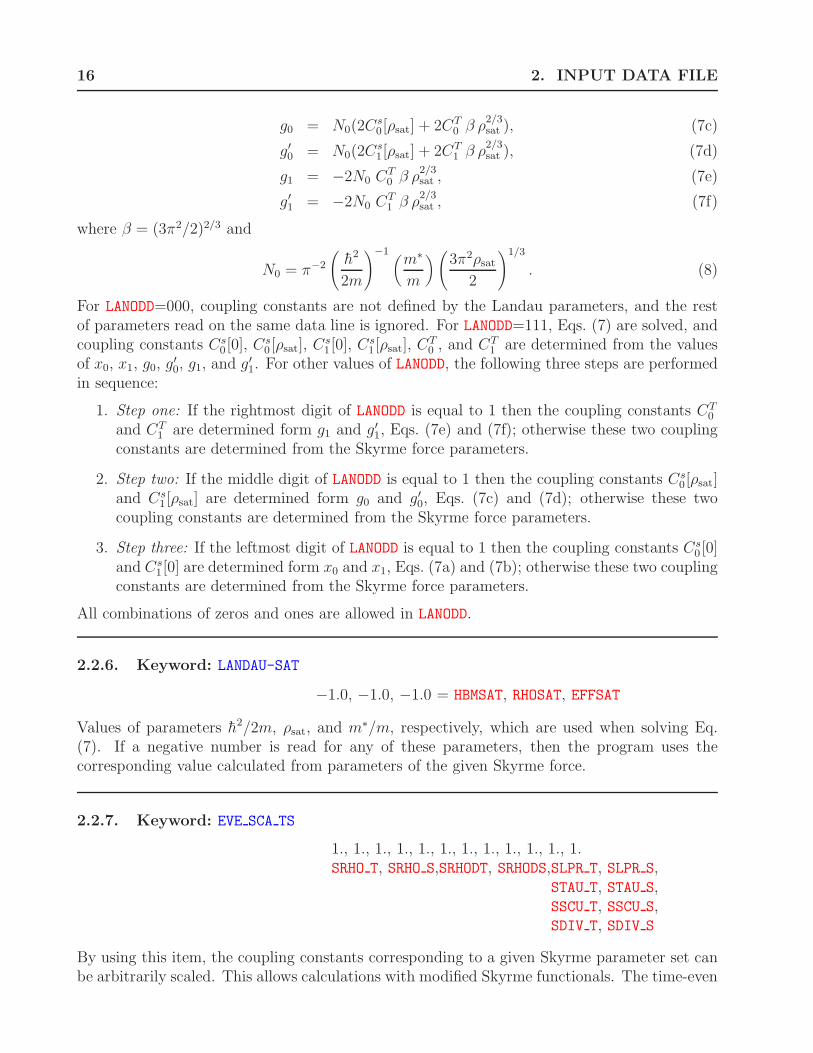
16 2. INPUT DATA FILE
g0 = N0(2Cs0[ρsat] + 2CT
0 β ρ2/3sat ), (7c)
g′
0 = N0(2Cs1[ρsat] + 2CT
1 β ρ2/3sat ), (7d)
g1 = −2N0 CT0 β ρ
2/3sat , (7e)
g′
1 = −2N0 CT1 β ρ
2/3sat , (7f)
where β = (3π2/2)2/3 and
N0 = π−2
(
h2
2m
)−1(
m∗
m
)
(
3π2ρsat
2
)1/3
. (8)
For LANODD=000, coupling constants are not defined by the Landau parameters, and the restof parameters read on the same data line is ignored. For LANODD=111, Eqs. (7) are solved, andcoupling constants Cs
0 [0], Cs0 [ρsat], Cs
1 [0], Cs1 [ρsat], CT
0 , and CT1 are determined from the values
of x0, x1, g0, g′
0, g1, and g′
1. For other values of LANODD, the following three steps are performedin sequence:
1. Step one: If the rightmost digit of LANODD is equal to 1 then the coupling constants CT0
and CT1 are determined form g1 and g′
1, Eqs. (7e) and (7f); otherwise these two couplingconstants are determined from the Skyrme force parameters.
2. Step two: If the middle digit of LANODD is equal to 1 then the coupling constants Cs0[ρsat]
and Cs1 [ρsat] are determined form g0 and g′
0, Eqs. (7c) and (7d); otherwise these twocoupling constants are determined from the Skyrme force parameters.
3. Step three: If the leftmost digit of LANODD is equal to 1 then the coupling constants Cs0 [0]
and Cs1 [0] are determined form x0 and x1, Eqs. (7a) and (7b); otherwise these two coupling
constants are determined from the Skyrme force parameters.
All combinations of zeros and ones are allowed in LANODD.
2.2.6. Keyword: LANDAU-SAT
−1.0, −1.0, −1.0 = HBMSAT, RHOSAT, EFFSAT
Values of parameters h2/2m, ρsat, and m∗/m, respectively, which are used when solving Eq.(7). If a negative number is read for any of these parameters, then the program uses thecorresponding value calculated from parameters of the given Skyrme force.
2.2.7. Keyword: EVE SCA TS
1., 1., 1., 1., 1., 1., 1., 1., 1., 1., 1., 1.SRHO T, SRHO S,SRHODT, SRHODS,SLPR T, SLPR S,
STAU T, STAU S,SSCU T, SSCU S,SDIV T, SDIV S
By using this item, the coupling constants corresponding to a given Skyrme parameter set canbe arbitrarily scaled. This allows calculations with modified Skyrme functionals. The time-even

2.2. Interaction 17
coupling constants in the total-sum representation,
Cρtot = Cρ
0 − Cρ1 , (9a)
Cρsum = 2Cρ
1 , (9b)
are multiplied by the 12 numbers from SRHO T to SDIV S. Variables with names ending with T
and S multiply the “total” and “sum” coupling constants, respectively. Variables with namescontaining the acronyms RHO, LPR, TAU, SCU, and DIV, multiply the coupling constants withsuperscripts ρ, ∆ρ, τ , J , and ∇J , respectively, and those with RHOD multiply the density-dependent part of Cρ. Similar name convention is used for many other variables in the codehfodd.
2.2.8. Keyword: ODD SCA TS
1., 1., 1., 1., 1., 1., 1., 1., 1., 1., 1., 1.SSPI T, SSPI S,SSPIDT, SSPIDS,SLPS T, SLPS S,
SCUR T, SCUR S,SKIS T, SKIS S,SROT T, SROT S
Same as above but for the time-odd coupling constants. The acronyms SPI, LPS, CUR, KIS, andROT correspond to coupling constants with superscripts s, ∆s, T , j, and ∇j, respectively, andthose with SPID correspond to the density-dependent part of Cs.
2.2.9. Keyword: EVE SCA PM
1., 1., 1., 1., 1., 1., 1., 1., 1., 1., 1., 1.SRHO P, SRHO M,SRHODP, SRHODM,SLPR P, SLPR M,
STAU P, STAU M,SSCU P, SSCU M,SDIV P, SDIV M
Same as above but for the time-even coupling constants in the isoscalar-isovector representation,
Cρ0 = 1
2Cρ
sum + Cρtot, (10a)
Cρ1 = 1
2Cρ
sum. (10b)
Variables with names ending with P and M multiply the isoscalar and isovector couplingconstants, respectively. The total-sum scaling factors are used first, and the isoscalar-isovectorscaling factors are used afterwards.

18 2. INPUT DATA FILE
2.2.10. Keyword: ODD SCA PM
1., 1., 1., 1., 1., 1., 1., 1., 1., 1., 1., 1.SSPI P, SSPI M,SSPIDP, SSPIDM,SLPS P, SLPS M,
SCUR P, SCUR M,SKIS P, SKIS M,SROT P, SROT M
Same as above but for the time-odd coupling constants in the isoscalar-isovector representation.
2.2.11. Keyword: EVE ADD TS
0., 0., 0., 0., 0., 0., 0., 0., 0., 0., 0., 0.ARHO T, ARHO S,ARHODT, ARHODS, ALPR T, ALPR S,
ATAU T, ATAU S,ASCU T, ASCU S,ADIV T, ADIV S
By using this item, the coupling constants corresponding to a given Skyrme parameter set canbe shifted by arbitrary values. The time-even coupling constants in the total-sum representation(I-14) are modified by adding the 12 numbers from ARHO T to ADIV S. By setting the scalingfactors SRHO T to SDIV S equal to zero, see the keyword EVE SCA TS, one can input here a newset of the coupling constants. The name convention of variables is here the same as for manyother variables in the code hfodd, see the keyword EVE SCA TS.
2.2.12. Keyword: ODD ADD TS
0., 0., 0., 0., 0., 0., 0., 0., 0., 0., 0., 0.ASPI T, ASPI S,ASPIDT, ASPIDS, ALPS T, ALPS S,
ACUR T, ACUR S,AKIS T, AKIS S,AROT T, AROT S
Same as above but for the time-odd coupling constants.
2.2.13. Keyword: EVE ADD PM
0., 0., 0., 0., 0., 0., 0., 0., 0., 0., 0., 0.ARHO P, ARHO M,ARHODP, ARHODM, ALPR P, ALPR M,
ATAU P, ATAU M,ASCU P, ASCU M,ADIV P, ADIV M
Same as above but for the time-even coupling constants in the isoscalar-isovector representation(10). The total-sum additive factors are used first, and the isoscalar-isovector additive factors

2.2. Interaction 19
are used afterwards.
2.2.14. Keyword: ODD ADD PM
0., 0., 0., 0., 0., 0., 0., 0., 0., 0., 0., 0.ASPI P, ASPI M,ASPIDP, ASPIDM, ALPS P, ALPS M,
ACUR P, ACUR M,AKIS P, AKIS M,AROT P, AROT M
Same as above but for the time-odd coupling constants in the isoscalar-isovector representation(10).
2.2.15. Keyword: G SCALING
1.0, 1.0 = FACTGN, FACTGP
For IPABCS=1 the code hfodd solves the BCS equations with the neutron and proton pairingstrengths defined in Ref. [9]. These values can be modified by defining here the multiplicativefactors FACTGN and FACTGP for neutrons and protons, respectively.
2.2.16. Keyword: PAIR MATRI
1, 0, 0, 0 = IDESTA, IDEMID, IDESTO, IDEDISFor IDESTA=1, the pairing matrix elements, required for the BCS pairing calculations withstate-dependent pairing gaps (IPABCS=3), are calculated in the first iteration. In the presentversion (v2.40h), only the value of IDESTA=1 is allowed, because the option of storing thepairing matrix elements is not yet implemented. For IDEMID=1, the pairing matrix elementsare calculated in the middle iterations (all between the first and the last one), for IDESTO=1 inthe last iteration, and/or for IDEDIS=n, in every n-th iteration, counting from the first one.
2.2.17. Keyword: INI FERMI
−8.0, −8.0 = FERINI(0), FERINI(1)
2.2.18. Keyword: INI DELTA
1.0, 1.0 = DELINI(0), DELINI(1)
For ICONTI=0 or ICONTI=1 and IPCONT=0, the HFB calculations are started by using the initialvalues of the neutron and proton Fermi energies, FERINI(0) and FERINI(1), and pairing gaps,DELINI(0) and DELINI(1). For ICONTI=1, the initial values of pairing gaps overwrite theHFB pairing potentials with constant values of DELINI(0) and DELINI(1) for neutrons andprotons, respectively. These constant potentials are ignored after the first iteration, i.e., in the

20 2. INPUT DATA FILE
first iteration, the mixing of previous and current potentials (see keyword SLOW-PAIR) is notperformed. A possibility of restarting calculations with nonzero pairing is very useful in casethe pairing would have vanished in a former run. For ICONTI=0 or IPCONT=0, values of FERINIand DELINI are ignored.
2.2.19. Keyword: FIXDELTA N
1.0, 0 = DELFIN, IDEFIN
For IDEFIN=1, the HFB pairing calculations (for IPAHFB=1) or BCS pairing calculations (forIPABCS=2) are performed with a fixed value of the neutron pairing gap equal to DELFIN. ForIDEFIN=0, value of DELFIN is ignored and the zero-range density-dependent pairing force (11)is used for neutrons. IDEFIN=1 requires IPAHFB=1 or IPABCS=2.
2.2.20. Keyword: FIXDELTA P
1.0, 0 = DELFIP, IDEFIP
Same as above but for the proton pairing gap.
2.2.21. Keyword: PAIRNFORCE
−200.0, 0.0, 1.0 = PRHO N, PRHODN, POWERN
Parameters V0, V1, and α, respectively, of the zero-range density-dependent pairing force definedby the pairing form-factor:
f(r) = V0 + V1ρα(r) = V0
(
1 −(
ρ(r)
ρ0
)α)
, (11)
which is used in the HFB pairing or BCS pairing calculations for neutrons. In case the valuesof V1 and α allow it, the code calculates the value of the saturation density ρ0 that gives theequivalent form of the pairing form-factor (11). In case ρ0 cannot be calculated, the codes setits value to 1; ρ0 is calculated only for the purpose of information, while internally the codeuses only the value of V1. For IDEFIN=1, or for IPAHFB6=1 and IPABCS6=3, parameters PRHO N,PRHODN, and POWERN are ignored.
2.2.22. Keyword: PAIRPFORCE
−200.0, 0.0, 1.0 = PRHO P, PRHODP, POWERP
Same as above but for the proton pairing force.

2.2. Interaction 21
2.2.23. Keyword: PAIR FORCE
−200.0, 0.0, 1.0 = PRHO T, PRHODT, POWERT
Same as above but for the neutron and proton pairing forces. This keyword is equivalent tousing the two keywords simultaneously, PAIRNFORCE and PAIRPFORCE, with identical parametersfor neutrons and protons.
2.2.24. Keyword: PAIRNINTER
−200.0, 0.16, 1.0 = PRHO N, PRHOSN, POWERN
Parameters V0, ρ0, and α, respectively, of the zero-range density-dependent pairing force (11),which is used in the HFB pairing or BCS pairing calculations for neutrons. In case the valuesof ρ0 and α allow it, the code calculates the value of V1 that gives the equivalent form of thepairing form-factor (11). In case V1 cannot be calculated, the code stops. For IDEFIN=1, or forIPAHFB6=1 and IPABCS6=3, parameters PRHO N, PRHOSN, and POWERN are ignored.
2.2.25. Keyword: PAIRPINTER
−200.0, 0.16, 1.0 = PRHO P, PRHOSP, POWERP
Same as above but for the proton pairing force.
2.2.26. Keyword: PAIR INTER
−200.0, 0.16, 1.0 = PRHO T, PRHOST, POWERT
Same as above but for the neutron and proton pairing forces. This keyword is equivalent tousing the two keywords simultaneously, PAIRNINTER and PAIRPINTER, with identical parametersfor neutrons and protons.
2.2.27. Keyword: CUTOFF
60.0 = ECUTOF
The cutoff energy emax for summing up contributions of the HFB quasiparticle states to densitymatrices, see Sec. IV-2.5. Ignored for IPAHFB=0.
2.2.28. Keyword: YUKAWATERM
0.7045, 4.7565, 1.0, 0.0, 0.0, 0.0, 1, 0PIMASS, PNMASS, YUKAGT, YUKAG0, YUKAG1, YUKAG2,IYUTYP, I YUKA
For I YUKA>0, the code calculates the average values of the time-reversal- and parity-violating

22 2. INPUT DATA FILE
Yukawa interaction (VI-59), with the pion mass (mπ) of PIMASS and the nucleon mass (mN) ofPNMASS. If values of zero are read, variables PIMASS and PNMASS remain unchanged. VariablesYUKAGT, YUKAG0, YUKAG1, and YUKAG2 correspond, respectively, to the coupling constants g,g0, g1, and g2, see Eq. (VI-59). For I YUKA=2 or 3, the direct matrix elements of the Yukawainteraction (VI-59) are, in addition, added to the self-consistent mean field. For I YUKA=2 or4, the exchange matrix elements are added. For IYUTYP=1, expression (VI-61) is used, whilefor IYUTYP=2, an analogous six-Gaussian expression is used without the short-range correction(VI-58), that is, for f(r) = 1. For I YUKA=0, all these input data are ignored and the Yukawainteraction is not taken into account.
Figures 1 and 2 show the actual CPU times required in calculations using the Skyrmeand Yukawa interactions, respectively. At N0 = 10, the latter take more than two orders ofmagnitude longer and, moreover, their CPU times scale like N7
0 rather than N40 . A local EDF
clearly makes for easier computing.
100
101
102CPU-time
6 128 1410
N0
CP
U t
ime
(sec
)
225Ra
10 iterations (Skyrme)
N02
N04
N06
Figure 1: The hfodd CPU times required for calculations that use the standard Skyrme EDF,shown as a function of the number of HO shells N0. The doubly logarithmic scale in the Figure,shows that these times scale as N4
0 .
2.2.29. Keyword: COULOMBPAR
7, 1, 1 = ICOTYP, ICOUDI, ICOUEXFor ICOUDI=0, 1, or 2, the Coulomb direct energy and Coulomb direct mean field are neglected,calculated by using the Green-function method, see Section I-5, or calculated by using theGaussian-expansion method, see Section VI-2.10, respectively. Similarly, for ICOUEX=0, 1, or2, the Coulomb exchange energy and Coulomb exchange mean field are neglected, calculatedby using the Slater approximation (I-19) or calculated exactly by using the Gaussian-expansionmethod, see Section VI-2.10, respectively. For the Gaussian-expansion method, that is, forICOUDI=2 or ICOUEX=2, positive values of ICOTYP denote the numbers of Gauss-Legendrenodes used in the integral of Eq. (VI-103). For ICOUDI=2 or ICOUEX=2, the iteration can laterbe smoothly continued (IFCONT=1, see the keyword CONTFIELDS) only by saving the matrix

2.2. Interaction 23
102
103
104
105
126 148 10
CPU time
N0
CP
U t
ime
(sec
)
225Ra
10 iterations (Yukawa)N0
5
N07
N09
Figure 2: Same as in Figure 1 but for calculations that use the Yukawa interaction. The CPUtimes scale as N7
0 .
elements of the mean field, that is, by requesting IWRIFI=1, see the keyword FIELD SAVE.Therefore, ICOUDI=2 or ICOUEX=2 and ICONTI=1 requires IFCONT=1.
In Fig. 3,the error in the exact Coulomb exchange energy is plotted as function of the numberof Gauss-Legendre nodes NC . A quite precise estimate is obtained for NC = 7 Gauss-Legendrenodes and the machine precision is obtained by doubling this number (along with doubling theCPU time). For NC = 7, these CPU times are shown in Fig. 4, which illustrates the fact thatthese times scale with the number of HO shells as N7
0 .
10-10
10-8
10-6
10-4
10-2
100
0 5 10 15
∆∆∆∆EExc>0
∆∆∆∆EExc<0
Number of Gaussians NC
| ∆∆ ∆∆E
exc|
(M
eV) 208Pb
Figure 3: Errors in the exact Coulomb exchange energy plotted in function of the number ofGauss-Legendre nodes NC .

24 2. INPUT DATA FILE
101
102
103
104CPU-time
6 128 1410
N0
CP
U t
ime
(sec
)
225Ra
10 iterations(Coulomb exchange)
N05
N07
N09
Figure 4: Same as in Figure 1 but for the calculations that determine the exact Coulombexchange energies. The CPU times scale as N7
0 .
2.2.30. Keyword: INSERT HO
0 = IPOTHO
For IPOTHO=1, an external HO potential is added to the self-consistent mean field. Parametersof the potential are identical to those defining the HO basis.

2.3. Symmetries 25
2.3. Symmetries
This section lists keywords pertaining to selection of conserved, broken, and restored symme-tries.
2.3.1. Keyword: SIMPLEXY
1 = ISIMPY
For ISIMPY=1, calculation with y-simplex conserved are performed, while for ISIMPY=0 thesimplex is broken. Value of ISIMPY must be consistent with switches IPARTY, ISIGNY, ISIMTY,and IROTAT, see Tables 1 and 2.
2.3.2. Keyword: SIGNATUREY
1 = ISIGNY
For ISIGNY=1, calculation with signature conserved are performed, while for ISIGNY=0 thesignature is broken. Value of ISIGNY must be consistent with switches ISIMPY, IPARTY, ISIMTX,and ISIMTZ, see Tables 1 and 3.
2.3.3. Keyword: PARITY
−1 = IPARTY
For IPARTY=1, calculation with parity conserved are performed, while for IPARTY=0 the parityis broken. Value of IPARTY must be consistent with switches ISIMPY and ISIGNY, see Table1. For IPARTY=−1 (the compatibility mode), the code sets IPARTY=ISIGNY and requires thatISIMPY=1
2.3.4. Keyword: ROTATION
1 = IROTAT
For IROTAT=1, calculation with time-reversal breaking are performed, while for IROTAT=0 thetime-reversal symmetry is conserved. In the latter case the calculations are performed onlyfor one value of the simplex, s=+i, which gives almost twice shorter CPU times. IROTAT=0is incompatible with providing a non-zero value of the angular frequency or with attemptingcalculation for odd or odd-odd nuclei without pairing, IPAIRI=0. IROTAT=1 is incompatiblewith IPABCS>0, i.e., the rotating solutions can be obtained for the HFB pairing but not for theBCS pairing.

26 2. INPUT DATA FILE
Table 1: Primary set of conserved and nonconserved symmetries allowed in the code hfodd
version (v2.40h).
Option Symmetries Switches
Sy Ry P ISIMPY ISIGNY IPARTY
P1 conserved conserved conserved 1 1 1P2 conserved nonconserved nonconserved 1 0 0P3 nonconserved conserved nonconserved 0 1 0P4 nonconserved nonconserved conserved 0 0 1P5 nonconserved nonconserved nonconserved 0 0 0
Table 2: Secondary set of conserved and nonconserved symmetries allowed in the code hfodd
version (v2.40h).
Option Symmetries Switches
Sy T STy ISIMPY ITIREV ISIMTY
S1 conserved conserved conserved 1 1 1S2 conserved nonconserved nonconserved 1 0 0S3 nonconserved conserved nonconserved 0 1 0S4 nonconserved nonconserved conserved 0 0 1S5 nonconserved nonconserved nonconserved 0 0 0
Table 3: Ternary set of conserved and nonconserved symmetries allowed in the code hfodd
version (v2.40h).
Option Symmetries Switches
Ry STx ST
z ISIGNY ISIMTX ISIMTZ
T1 conserved conserved conserved 1 1 1T2 conserved nonconserved nonconserved 1 0 0T3 nonconserved conserved nonconserved 0 1 0T4 nonconserved nonconserved conserved 0 0 1T5 nonconserved nonconserved nonconserved 0 0 0

2.3. Symmetries 27
2.3.5. Keyword: TIMEREVERS
0 = ITIREV
For ITIREV=1, calculation with time-reversal conserved are performed, while for ITIREV=0 thissymmetry is broken. This switch is used only as a convenient replacement of switch IROTAT;ITIREV=1 is equivalent to IROTAT=0 and ITIREV=0 is equivalent to IROTAT=1.
2.3.6. Keyword: TSIMPLEX Y
−1 = ISIMTY
For ISIMTY=1, calculation with y-simplexT conserved are performed, while for ISIMTY=0 thissymmetry is broken. Value of ISIMTY must be consistent with switches ISIMPY and IROTAT,see Table 2. For ISIMTY=−1 (the compatibility mode), the code sets ISIMTY to 1-IROTAT andrequires that ISIMPY=1.
2.3.7. Keyword: TSIMPLEXES
1, 1 = ISIMTX, ISIMTZ
For ISIMTX=1 and/or ISIMTZ=1, calculation with conserved symmetries given by x-simplexT
and/or z-simplexT are performed, respectively. These symmetries are broken for ISIMTX=0 andISIMTZ=0. Values of ISIMTX and ISIMTZ must be consistent with that of ISIGNY, see Table 3.
2.3.8. Keyword: TSIMPLEX3D
1, −1, 1 = ISIMTX, ISIMTY, ISIMTZ
This keyword allows to simultaneously input all the three switches that define the three T -simplexes. It is equivalent to using keywords TSIMPLEXES and TSIMPLEX Y together.
2.3.9. Keyword: PAIRING
0 = IPAIRI
For IPAIRI=0, calculation without pairing correlations (pure HF) are performed, while forIPAIRI=1 the pairing correlations are included. In the latter case, for IPAHFB=0 or 1 pairing isincluded within the BCS or HFB method, respectively. IPAIRI=1 requires either IPAHFB=1 orIPABCS>0 and is incompatible with simultaneously setting IPAHFB=1 and IPABCS>0, i.e., theHFB pairing and BCS pairing cannot be used simultaneously. IPAIRI=1 is incompatible withIROTAT=1, unless IPAHFB=1, i.e., the rotating solutions can be obtained for the HFB pairingbut not for the BCS pairing.
28 2. INPUT DATA FILE
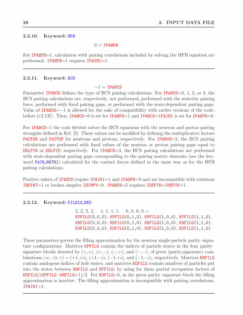
2.3.10. Keyword: HFB
0 = IPAHFB
For IPAHFB=1, calculation with pairing correlations included by solving the HFB equation areperformed. IPAHFB=1 requires IPAIRI=1.
2.3.11. Keyword: BCS
−1 = IPABCS
Parameter IPABCS defines the type of BCS pairing calculations. For IPABCS=0, 1, 2, or 3, theBCS pairing calculations are, respectively, not performed, performed with the seniority pairingforce, performed with fixed pairing gaps, or performed with the state-dependent pairing gaps.Value of IPABCS=−1 is allowed for the sake of compatibility with earlier versions of the code,before (v2.13f). Then, IPABCS=0 is set for IPAHFB=1 and IPABCS=IPAIRI is set for IPAHFB=0.
For IPABCS=1 the code hfodd solves the BCS equations with the neutron and proton pairingstrengths defined in Ref. [9]. These values can be modified by defining the multiplicative factorsFACTGN and FACTGP for neutrons and protons, respectively. For IPABCS=2, the BCS pairingcalculations are performed with fixed values of the neutron or proton pairing gaps equal toDELFIN or DELFIP, respectively. For IPABCS=3, the BCS pairing calculations are performedwith state-dependent pairing gaps corresponding to the pairing matrix elements (see the key-word PAIR MATRI) calculated for the contact forces defined in the same way as for the HFBpairing calculations.
Positive values of IPABCS require IPAIRI=1 and IPAHFB=0 and are incompatible with rotationsIROTAT=1 or broken simplex ISIMPY=0. IPABCS=2 requires IDEFIN=IDEFIP=1.
2.3.12. Keyword: FILSIG NEU
2, 2, 2, 2, 1, 1, 1, 1, 0, 0, 0, 0 =KPFILG(0,0,0), KPFILG(0,1,0), KPFILG(1,0,0), KPFILG(1,1,0),KHFILG(0,0,0), KHFILG(0,1,0), KHFILG(1,0,0), KHFILG(1,1,0),KOFILG(0,0,0), KOFILG(0,1,0), KOFILG(1,0,0), KOFILG(1,1,0)
These parameters govern the filling approximation for the neutron single-particle parity–signa-ture configurations. Matrices KPFILG contain the indices of particle states in the four parity–signature blocks denoted by (+,+), (+,−), (−,+), and (−,−), of given (parity,signature) com-binations, i.e., (π, r) = (+1,+i), (+1,−i), (−1,+i), and (−1,−i), respectively. Matrices KHFILGcontain analogous indices of hole states, and matrices KOFILG contain numbers of particles putinto the states between KHFILG and KPFILG, by using for them partial occupation factors ofKOFILG/(KPFILG−KHFILG+1)/2. For KOFILG=0, in the given parity–signature block the fillingapproximation is inactive. The filling approximation is incompatible with pairing correlations,IPAIRI=1.

2.3. Symmetries 29
2.3.13. Keyword: FILSIG PRO
2, 2, 2, 2, 1, 1, 1, 1, 0, 0, 0, 0 =KPFILG(0,0,1), KPFILG(0,1,1), KPFILG(1,0,1), KPFILG(1,1,1),KHFILG(0,0,1), KHFILG(0,1,1), KHFILG(1,0,1), KHFILG(1,1,1),KOFILG(0,0,1), KOFILG(0,1,1), KOFILG(1,0,1), KOFILG(1,1,1)
Same as above but for the proton single-particle parity–signature configurations.
2.3.14. Keyword: INI INVERS
0, 0 = INIINV, INIKARAllowed values of INIKAR=0, 1, 2, or 3 and INIINV=0, 1, 2, or 3 correspond to the followinginitial DT
2h transformations:
INIKAR=0 INIKAR=1 INIKAR=2 INIKAR=3
INIINV=0 I Rx Ry Rz
INIINV=1 P Sx Sy Sz
INIINV=2 T RTx RT
y RTz
INIINV=3 P T STx ST
y STz
where P is the space inversion, T is the time-reversal symmetry, Rk is the signature (rotationby angle π about the k = x, y, or z axis), and P T = P T , Sk = P Rk (simplex), RT
k = T Rk
(k-signatureT ), and STk = T Sk (k-simplexT ). For INIKAR=INIINV=0, no transformation is per-
formed and this option is inactive.
Transformations are performed at the level of the densities, after the first iteration. As a secu-rity measure, nonzero values of INIKAR and INIINV require NOITER=1. Such values also requireSLOWEV=SLOWOD=SLOWPA=0.0, so as not to mix the old and new potentials corresponding tothe original and transformed densities, respectively. They are also incompatible with IPRGCM6=0.
A given initial DT2h transformation must be accompanied by the correspondingly broken sym-
metries, that is, INIINV=1 or 3 requires IROTAT=1 and INIINV=2 or 3 requires IPARTY=0.
2.3.15. Keyword: INI ROTAT
0.0, 0.0, 0.0, 0 = ALPINI, BETINI, GAMINI, INIROTFor INIROT=1, the wave functions are rotated by the Euler angles α, β, and γ corresponding,respectively, to ALPINI, BETINI, and GAMINI (all in degrees). Transformations are performedat the level of the densities, after the first iteration. As a security measure, INIROT=1 requiresNOITER=1. It also requires SLOWEV=SLOWOD=SLOWPA=0.0, so as not to mix the old and newpotentials corresponding to the original and transformed densities, respectively. INIROT=1 isincompatible with IPRGCM6=0 and requires a spherical HO basis of hωx = hωy = hωz.

30 2. INPUT DATA FILE
A rotation about the z axis must be accompanied by the broken signature, that is, ALPINI6=0or GAMINI6=0 requires ISIGNY=0.
2.3.16. Keyword: PROJECTGCM
0, 0, 0, 1, 1, 0, 1, 1, 0IPRGCM, IPROMI, IPROMA, NUAKNO, NUBKNO, KPROJE,
IFRWAV, ITOWAV, IWRWAV
For IPRGCM=1 and 2, the code calculates the diagonal and non-diagonal GCM kernels, respec-tively. In addition, for NUAKNO6=1 or NUBKNO6=1, the AMP kernels are calculated, as describedin Section VI-2.1, although in the present version (v2.40h) this option is not yet available fornon-diagonal kernels of IPRGCM=2. The angular momentum projection (AMP) is performedfor doubled angular momenta from IPROMI to IPROMA and requires a spherical HO basis ofhωx = hωy = hωz. For even (odd) particle number IN FIX+IZ FIX, IPROMI, IPROMA, andKPROJE must be even (odd). For IPRGCM=1 and 2, the present version (v2.40h) also requiresIROTAT=1 and IPAIRI=0.
The AMP has been tested up to the values of angular momenta of 70h, and therefore, IPROMAmust not be larger than 2*70=140. After further tests, higher values could be used by increas-ing the parameter JMAX=70 in function dsmalg, which calculates the Wigner functions, seeEqs. (VI-1), (VI-4), and (VI-5).
NUAKNO is the number of Gauss-Tchebyschev nodes, which are used to perform integrations overthe α and γ Euler angles. For NUAKNO=1, these integrations are not performed (1D AMP) andthe states are assumed to be axial with the doubled projection of the angular momentum onthe z axis equal to KPROJE. NUBKNO is the number of Gauss-Legendre nodes, which are used toperform integrations over the β Euler angle. For NUAKNO>1 and NUBKNO>1, a full 3D AMP isperformed and the value of KPROJE is ignored. NUAKNO>1 requires ISIMPY=0 and ISIGNY=0.IPROMA must be larger than the absolute value of KPROJE.
For IPRGCM=2, the code calculates the GCM kernels between the states labeled by three-digitindices from ”000” to ”999”. Indices of the ”left” states vary between IFRWAV and ITOWAV,and these states are read from the disc. The index of the ”right” state equals to ITOWAV, andthis state is equal to the current state. In addition, for IWRWAV=1, the current state is savedon the disc with the index of ITOWAV. This allows for a simultaneous calculation of the ”right”state along with calculating its kernels with all previously calculated and stored ”left” states.The states can also be stored on disc without calculating kernels in the given run, that is, bysetting the value of ITOWAV along with IWRWAV=1 and IPRGCM=0. Names of files on the discare composed by concatenating the three-digit index, ”-”, and FILWAV.
2.3.17. Keyword: SAVEKERNEL
0 = ISAKER

2.3. Symmetries 31
For ISAKER=1, the code attempts reading the kernel files Nxxx-Lyyy-Rzzz-//FILKER, where //denotes concatenated strings. The three-digit indices are:
• xxx is the consecutive index of the kernel file,
• yyy is the index of the left wave function,
• zzz is the index of the right wave function.
In the work directory, the file names for all indices xxx are scanned, starting from 001. Thekernels stored in these files are read into memory and are not recalculated. The kernels thathave not been found in the kernel files are calculated and stored in the kernel file with thelowest available index xxx. In this way, one can submit many parallel jobs, see the keywordPARAKERNEL, that calculate kernels for different values of the Euler angles α, β, and γ. Theresults are then collected in different kernel files with indices xxx attributed automatically. Ifany of the jobs is terminated before completing its task, the same input data can be resubmittedand the calculation automatically continues from the point where it has been interrupted. Onceall the kernels will have been calculated, which requires a large CPU time, the AMP can beperformed within a very small CPU time by reading, again automatically, all the created kernelfiles. ISAKER=1 requires IPRGCM>0
2.3.18. Keyword: CHECKERNEL
1 = ICHKER
The names of kernel files are saved within these files. As a security measure, when reading thekernel files, their names are cross-checked against the saved information. This cross-checkingcan be deactivated by using ICHKER=0. This option is useful whenever the kernel files havebeen renamed for any reason.
2.3.19. Keyword: PARAKERNEL
0, 1, 1, 1, 1 = IPAKER, NUASTA, NUASTO, NUGSTA, NUGSTOFor IPAKER=1, the code only calculates kernels for different values of the Euler angles α, β, andγ and the AMP is suspended. Calculations are performed for the Gauss-Tchebyschev nodesin the Euler angle α from NUASTA to NUASTO, for those in the Euler angle γ from NUGSTA toNUGSTO, and for all the Gauss-Legendre nodes in the Euler angle β, that is, from 1 to NUBKNO.For IPAKER=1, to save memory, the code can be compiled with IPARAL=1. IPAKER=1 requiresIPRGCM>0 and ISAKER=1. Values of NUASTA, NUASTO, NUGSTA, NUGSTO must all be between 1and NUAKNO and must be ordered as NUASTA≤NUASTO and NUGSTA≤NUGSTO.
2.3.20. Keyword: TRANSITION
2, 1, 0 = NMURED, NMARED, NSIREDMaximum numbers of transition electric, transition magnetic, and transition surface or Schiffmoments, respectively, for which proton kernels and reduced matrix elements are calculated,

32 2. INPUT DATA FILE
printed, and stored in the kernel files. NMARED and NSIRED must not exceed NMURED. ForNMURED=0, NMARED=0, or NSIRED, the corresponding proton kernels and reduced matrix ele-ments are not calculated.
2.3.21. Keyword: CUTOVERLAP
0, 10−10, 1. = ICUTOV, CUTOVE, CUTOVF
For ICUTOV=0, parameters CUTOVE and CUTOVF are ignored and the collective states for theK-mixing calculation, Eq. (VI-10), are selected by their norm eigenvalues nm being larger thanthe negative of the smallest norm eigenvalue OVEMIN. For ICUTOV=1, the collective states areselected by their norm eigenvalues being larger than CUTOVE+CUTOVF*OVEMIN.
2.3.22. Keyword: LIPKIN
0, 0 = LIPKIN, LIPKIP
For LIPKIN=1 and/or LIPKIP=1, the Lipkin-Nogami corrections are included for neutronsand/or protons, respectively, see Section VI-29. In the present version (v2.40h), LIPKIN=1 orLIPKIP=1 requires IPAHFB=1.
2.3.23. Keyword: INI LIPKIN
0.1, 0.1 = FE2INI(0), FE2INI(1)
For IPCONT=0, or IPCONT=1 and ILCONT=0, the Lipkin-Nogami calculations are started byusing the initial values of the neutron and proton Lipkin-Nogami parameters λ2 (VI-98),FE2INI(0) and FE2INI(1), respectively. For IPCONT=1 and ILCONT=1, values of FE2INI areignored.
2.3.24. Keyword: FIXLAMB2 N
0.1, 0 = FE2FIN, IF2FIN
For IF2FIN=1, the neutron Lipkin-Nogami calculations are performed by using the fixed valueof the neutron Lipkin-Nogami parameter λ2 (VI-98) equal to FE2FIN. IF2FIN=1 requiresLIPKIN=1.
2.3.25. Keyword: FIXLAMB2 P
0.1, 0 = FE2FIP, IF2FIP
Same as above but for the proton Lipkin-Nogami calculations.

2.3. Symmetries 33
2.3.26. Keyword: SLOWLIPKIN
0.5 = SLOWLI
SLOWLI gives the value of the mixing fraction ǫ used for the Lipkin-Nogami parameter λ2 (VI-98), in analogy to the SLOWEV, SLOWOD and SLOWPA parameters.
2.3.27. Keyword: FIXFERMI N
-8.0, 0 = FERFIN, IFEFINFor IFEFIN=1, the HFB pairing calculations are performed with a fixed value of the neutronFermi energy equal to FERFIN. In the present version (v2.40h), IFEFIN=1 requires IPAHFB=1.
2.3.28. Keyword: FIXFERMI P
-8.0, 0 = FERFIP, IFEFIPSame as above but for the proton HFB pairing calculations.

34 2. INPUT DATA FILE
2.4. Configurations with no conserved symmetries
This section lists keywords pertaining to definitions of configurations in the case when nosymmetries are conserved, and the single-particle or single-quasiparticle space is divided intotwo charge blocks (neutrons and protons).
2.4.1. Keyword: PHNONE NEU
1, 00, 00 = NUPAHO, KPNONE, KHNONE
Neutron particle-hole excitations pertaining to the situation when all neutrons are in one com-mon block (no simplex, signature, or parity is conserved). NUPAHO is the consecutive numberfrom 1 to 5 (up to five sets of excitations can be specified in separate items). Particles are re-moved from the KHNONE-th state and put in the KPNONE-th state. At every stage of constructingexcitations the Pauli exclusion principle has to be respected (particle removed from an occupiedstate and put in an empty state). Values equal zero have no effect. Note that for all neutronssitting in one common block the reference configuration from which the particle-hole excita-tions are counted is defined by the total number of neutrons. These particle-hole excitationsare ignored unless ISIMPY=0, IPARTY=0, and IPAIRI=0.
2.4.2. Keyword: PHNONE PRO
1, 00, 00 = NUPAHO, KPNONE, KHNONE
Same as above but for the proton particle-hole excitations.
2.4.3. Keyword: DIANON NEU
2, 1, 0 = KPFLIZ, KHFLIZ, KOFLIZ
The diabatic blocking of neutron single-particle configurations in the situation when all neutronsare in one common block. The rules to define the blocking are analogous to those described forthe conserved parity, keyword DIAPAR NEU.
2.4.4. Keyword: DIANON PRO
2, 1, 0 = KPFLIZ, KHFLIZ, KOFLIZ
Same as above but for the diabatic blocking of proton single-particle configurations in thesituation when all protons are in one common block.
2.4.5. Keyword: BLOCKSIZ N
1, 0 = INSIZN, IDSIZN

2.4. Configurations with no conserved symmetries 35
For |IDSIZN|=1, the code performs the neutron quasiparticle blocking calculations in the casewhen no symmetries are conserved, see Section VI-2.7. For IDSIZN=+1 or −1, the blockedquasiparticle state is selected by having the largest overlap with the INSIZN-th neutron single-particle eigenstate of the HFB mean-field Routhian or with its time-reversed partner, respec-tively. Note that for rotating states, the time-reversed eigenstate is not necessarily an eigenstateof the Routhian. |IDSIZN|=1 requires ISIMPY=0, IPARTY=0, IPAHFB=1, and IROTAT=1.
2.4.6. Keyword: BLOCKSIZ P
1, 0 = INSIZP, IDSIZPSame as above but for the proton quasiparticle blocking. For odd-odd nuclei, neutron andproton quasiparticles can be simultaneously blocked.

36 2. INPUT DATA FILE
2.5. Configurations with conserved simplex
This section lists keywords pertaining to definitions of configurations in the case when simplexis conserved, and the single-particle or single-quasiparticle space is divided into four charge–simplex blocks (neutrons and protons with simplexes s=±i).
2.5.1. Keyword: VACSIM NEU
43, 43 = KVASIM(0), KVASIM(1)
Numbers of lowest neutron states occupied in the two simplex blocks, denoted by (+) and (−),of given simplexes, s=+i and s=−i, respectively. These numbers define the simplex referenceconfiguration from which the particle-hole excitations are counted. The definitions of simplexreference configuration and excitations are ignored unless ISIMPY=1, ISIGNY=0, and IPAIRI=0.
2.5.2. Keyword: VACSIM PRO
33, 33 = KVASIM(0), KVASIM(1)
Same as above but for the numbers of proton states.
2.5.3. Keyword: PHSIMP NEU
1, 00, 00, 00, 00 = NUPAHO, KPSIMP, KPSIMM, KHSIMP, KHSIMM
Neutron particle-hole excitations in the simplex blocks. NUPAHO is the consecutive number from1 to 5 (up to five sets of excitations can be specified in separate items). Particles are removedfrom the KHSIMP-th state in the (+) block and from the KHSIMM-th state in the (−) block,and put in the KPSIMP-th state in the (+) block and in the KPSIMM-th state in the (−) block.At every stage of constructing excitations the Pauli exclusion principle has to be respected(particle removed from an occupied state and put in an empty state). Values equal zero haveno effect. In practice, reasonable excitations can only be constructed by consulting the printedlists of single-particle states with their consecutive numbers in given blocks. These particle-holeexcitations are ignored unless ISIMPY=1, ISIGNY=0, and IPAIRI=0.
2.5.4. Keyword: PHSIMP PRO
1, 00, 00, 00, 00 = NUPAHO, KPSIMP, KPSIMM, KHSIMP, KHSIMM
Same as above but for the proton particle-hole excitations.

2.5. Configurations with conserved simplex 37
2.5.5. Keyword: DIASIM NEU
2, 2, 1, 1, 0, 0 = KPFLIM(0,0), KPFLIM(1,0),KHFLIM(0,0), KHFLIM(1,0),KOFLIM(0,0), KOFLIM(1,0)
The diabatic blocking of neutron single-particle simplex configurations. Matrices KPFLIM con-tain the indices of the particle states in the two simplex blocks denoted by (+) and (−), of givensimplex values, i.e., s=+i and −i, respectively. Matrices KHFLIM contain analogous indices ofthe hole states, and matrices KOFLIM define types of blocking in analogy to those shown inTable 4:
2.5.6. Keyword: DIASIM PRO
2, 2, 1, 1, 0, 0 = KPFLIM(0,1), KPFLIM(1,1),KHFLIM(0,1), KHFLIM(1,1),KOFLIM(0,1), KOFLIM(1,1)
Same as above but for the diabatic blocking of proton single-particle simplex configurations.
2.5.7. Keyword: BLOCKSIM N
1, 0, 0 = INSIMN, IRSIMN, IDSIMNFor |IDSIMN|=1, the code performs the neutron quasiparticle blocking calculations in the casewhen simplex is conserved, see Section VI-2.7. For IDSIMN=+1 or −1, the blocked quasiparticlestate is selected by having the largest overlap with the INSIMN-th neutron single-particle eigen-state of the HFB mean-field Routhian in a given simplex block or with its time-reversed partner,respectively. The simplex of the state, +i or −i, is defined by IRSIMN=0 or 1, respectively.|IDSIMN|=1 requires ISIMPY=1, IPARTY=0, IPAHFB=1, and IROTAT=1.
2.5.8. Keyword: BLOCKSIM P
1, 0, 0 = INSIMP, IRSIMP, IDSIMPSame as above but for the proton quasiparticle blocking. For odd-odd nuclei, neutron andproton quasiparticles can be simultaneously blocked.

38 2. INPUT DATA FILE
2.6. Configurations with conserved parity
This section lists keywords pertaining to definitions of configurations in the case when parity isconserved, and the single-particle or single-quasiparticle space is divided into four charge–parityblocks (neutrons and protons with parities π=±1).
2.6.1. Keyword: VACPAR NEU
44, 42 = KVASIQ(0), KVASIQ(1)
Numbers of lowest neutron states occupied in the two parity blocks, denoted by (+1) and(−1), of given parities, π=+1 and π=−1, respectively. These numbers define the parity ref-erence configuration from which the particle-hole excitations are counted. The definitions ofparity reference configuration and excitations are ignored unless IPARTY=1, or IPARTY=−1 andISIMPY=ISIGNY=1. They are also ignored for ISIMPY=1 and IPAIRI=1.
2.6.2. Keyword: VACPAR PRO
32, 34 = KVASIQ(0), KVASIQ(1)
Same as above but for the numbers of proton states.
2.6.3. Keyword: PHPARI NEU
1, 00, 00, 00, 00 = NUPAHO, KPSIQP, KPSIQM, KHSIQP, KHSIQM
Neutron particle-hole excitations in the parity blocks. NUPAHO is the consecutive number from1 to 5 (up to five sets of excitations can be specified in separate items). Particles are removedfrom the KHSIQP-th state in the (+1) block and from the KHSIQM-th state in the (−1) block, andput in the KPSIQP-th state in the (+1) block and in the KPSIQM-th state in the (−1) block. Atevery stage of constructing excitations the Pauli exclusion principle has to be respected (particleremoved from an occupied state and put in an empty state). Values equal zero have no effect.These particle-hole excitations are ignored unless ISIMPY=0, IPARTY=1, and IPAIRI=0.
2.6.4. Keyword: PHPARI PRO
1, 00, 00, 00, 00 = NUPAHO, KPSIQP, KPSIQM, KHSIQP, KHSIQM
Same as above but for the proton particle-hole excitations.

2.6. Configurations with conserved parity 39
2.6.5. Keyword: DIAPAR NEU
2, 2, 1, 1, 0, 0 = KPFLIQ(0,0), KPFLIQ(1,0),KHFLIQ(0,0), KHFLIQ(1,0),KOFLIQ(0,0), KOFLIQ(1,0)
The diabatic blocking of neutron single-particle parity configurations. Matrices KPFLIQ containthe indices of the particle states in the two parity blocks denoted by (+1) and (−1), of givenparities, i.e., π=+1 and −1, respectively. Matrices KHFLIQ contain analogous indices of thehole states, and matrices KOFLIQ define the type of blocking according to definitions shown inTable 4:
Table 4: Values of parameter KOFLIQ that specify type of blocking in case of conserved parity.Analogous values define type of blocking for other conserved symmetries.
KOFLIQ=0 ⇐⇒ No diabatic blocking in the given parity block.KOFLIQ=+1 ⇐⇒ The state which has the larger y-alignment is occupied.KOFLIQ=−1 ⇐⇒ The state which has the smaller y-alignment is occupied.KOFLIQ=+2 ⇐⇒ The state which has the larger y-intrinsic spin is occupied.KOFLIQ=−2 ⇐⇒ The state which has the smaller y-intrinsic spin is occupied.KOFLIQ=+3 ⇐⇒ The state which has the larger x-alignment is occupied.KOFLIQ=−3 ⇐⇒ The state which has the smaller x-alignment is occupied.KOFLIQ=+4 ⇐⇒ The state which has the larger x-intrinsic spin is occupied.KOFLIQ=−4 ⇐⇒ The state which has the smaller x-intrinsic spin is occupied.KOFLIQ=+5 ⇐⇒ The state which has the larger z-alignment is occupied.KOFLIQ=−5 ⇐⇒ The state which has the smaller z-alignment is occupied.KOFLIQ=+6 ⇐⇒ The state which has the larger z-intrinsic spin is occupied.KOFLIQ=−6 ⇐⇒ The state which has the smaller z-intrinsic spin is occupied.KOFLIQ=+7 ⇐⇒ The state which has the larger o-alignment is occupied.KOFLIQ=−7 ⇐⇒ The state which has the smaller o-alignment is occupied.KOFLIQ=+8 ⇐⇒ The state which has the larger o-intrinsic spin is occupied.KOFLIQ=−8 ⇐⇒ The state which has the smaller o-intrinsic spin is occupied.KOFLIQ=+9 ⇐⇒ The state which has the larger multipole moment Q20 is occupied.KOFLIQ=−9 ⇐⇒ The state which has the smaller multipole moment Q20 is occupied.KOFLIQ=+10 ⇐⇒ The state which has the larger multipole moment Q22 is occupied.KOFLIQ=−10 ⇐⇒ The state which has the smaller multipole moment Q22 is occupied.
Here, the x-, y-, and z-alignments or intrinsic spins denote projections of the total angularmomentum or spin, respectively, on the x, y, and z axes. Similarly, the o-alignment or o-intrinsicspin denotes analogous projections on the direction of the angular frequency ωJ .
Within the diabatic blocking procedure one does not predefine whether the particle or thehole state is occupied (as is the case when the particle-hole excitations are defined, see Section3.4 of II). In each iteration the code calculates the average alignments (or average intrinsicspins, or average quadrupole moments) of both states (those defined by KPFLIM and KHFLIM),and occupies that state for which a larger, or a smaller value is obtained. Therefore, the order

40 2. INPUT DATA FILE
of both states in the Routhian spectrum is irrelevant.The user is responsible for choosing the particle-state indices (in KPFLIM) only among those
corresponding to empty single-particle states, and the hole-state indices (in KHFLIM) only amongthose corresponding to occupied single-particle states.
2.6.6. Keyword: DIAPAR PRO
2, 2, 1, 1, 0, 0 = KPFLIQ(0,1), KPFLIQ(1,1),KHFLIQ(0,1), KHFLIQ(1,1),KOFLIQ(0,1), KOFLIQ(1,1)
Same as above but for the diabatic blocking of proton single-particle parity configurations.
2.6.7. Keyword: BLOCKSIQ N
1, 0, 0 = INSIQN, IPSIQN, IDSIQNFor |IDSIQN|=1, the code performs the neutron quasiparticle blocking calculations in the casewhen parity is conserved. For IDSIQN=+1 or −1, the blocked quasiparticle state is selectedby having the largest overlap with the INSIQN-th neutron single-particle eigenstate of the HFBmean-field Routhian in a given parity block or with its time-reversed partner, respectively. Theparity of the state, +1 or −1, is defined by IPSIQN=0 or 1, respectively. |IDSIQN|=1 requiresISIMPY=0, IPARTY=1, IPAHFB=1, and IROTAT=1.
2.6.8. Keyword: BLOCKSIQ P
1, 0, 0 = INSIQP, IPSIQP, IDSIQPSame as above but for the proton quasiparticle blocking. For odd-odd nuclei, neutron andproton quasiparticles can be simultaneously blocked.
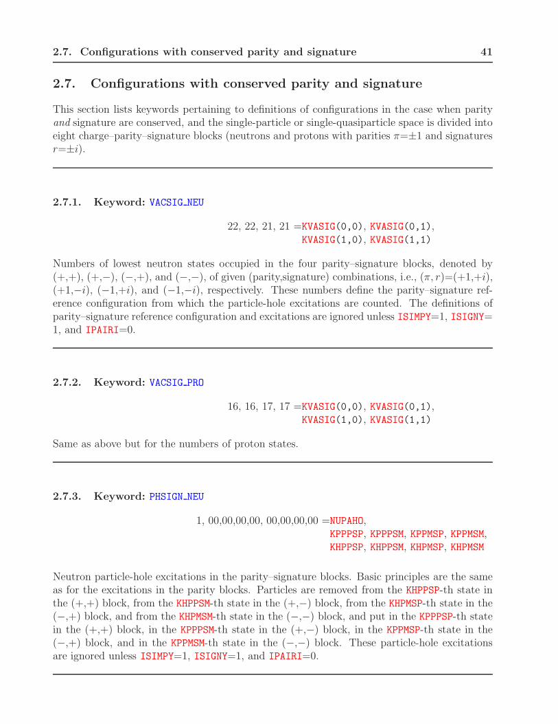
2.7. Configurations with conserved parity and signature 41
2.7. Configurations with conserved parity and signature
This section lists keywords pertaining to definitions of configurations in the case when parityand signature are conserved, and the single-particle or single-quasiparticle space is divided intoeight charge–parity–signature blocks (neutrons and protons with parities π=±1 and signaturesr=±i).
2.7.1. Keyword: VACSIG NEU
22, 22, 21, 21 =KVASIG(0,0), KVASIG(0,1),KVASIG(1,0), KVASIG(1,1)
Numbers of lowest neutron states occupied in the four parity–signature blocks, denoted by(+,+), (+,−), (−,+), and (−,−), of given (parity,signature) combinations, i.e., (π, r)=(+1,+i),(+1,−i), (−1,+i), and (−1,−i), respectively. These numbers define the parity–signature ref-erence configuration from which the particle-hole excitations are counted. The definitions ofparity–signature reference configuration and excitations are ignored unless ISIMPY=1, ISIGNY=1, and IPAIRI=0.
2.7.2. Keyword: VACSIG PRO
16, 16, 17, 17 =KVASIG(0,0), KVASIG(0,1),KVASIG(1,0), KVASIG(1,1)
Same as above but for the numbers of proton states.
2.7.3. Keyword: PHSIGN NEU
1, 00,00,00,00, 00,00,00,00 =NUPAHO,KPPPSP, KPPPSM, KPPMSP, KPPMSM,KHPPSP, KHPPSM, KHPMSP, KHPMSM
Neutron particle-hole excitations in the parity–signature blocks. Basic principles are the sameas for the excitations in the parity blocks. Particles are removed from the KHPPSP-th state inthe (+,+) block, from the KHPPSM-th state in the (+,−) block, from the KHPMSP-th state in the(−,+) block, and from the KHPMSM-th state in the (−,−) block, and put in the KPPPSP-th statein the (+,+) block, in the KPPPSM-th state in the (+,−) block, in the KPPMSP-th state in the(−,+) block, and in the KPPMSM-th state in the (−,−) block. These particle-hole excitationsare ignored unless ISIMPY=1, ISIGNY=1, and IPAIRI=0.

42 2. INPUT DATA FILE
2.7.4. Keyword: PHSIGN PRO
1, 00,00,00,00, 00,00,00,00 =NUPAHO,KPPPSP, KPPPSM, KPPMSP, KPPMSM,KHPPSP, KHPPSM, KHPMSP, KHPMSM
Same as above but for the proton particle-hole excitations.
2.7.5. Keyword: DIASIG NEU
2, 2, 2, 2, 1, 1, 1, 1, 0, 0, 0, 0 =KPFLIG(0,0,0), KPFLIG(0,1,0), KPFLIG(1,0,0), KPFLIG(1,1,0),KHFLIG(0,0,0), KHFLIG(0,1,0), KHFLIG(1,0,0), KHFLIG(1,1,0),KOFLIG(0,0,0), KOFLIG(0,1,0), KOFLIG(1,0,0), KOFLIG(1,1,0)
The diabatic blocking of neutron single-particle parity–signature configurations. MatricesKPFLIG contain the indices of particle states in the four parity–signature blocks denoted by(+,+), (+,−), (−,+), and (−,−), of given (parity,signature) combinations, i.e., (π, r) = (+1,+i),(+1,−i), (−1,+i), and (−1,−i), respectively. Matrices KHFLIG contain analogous indices of holestates, and matrices KOFLIG define the type of blocking according to Table 4. Other rules de-scribed for the parity case apply here analogously.
2.7.6. Keyword: DIASIG PRO
2, 2, 2, 2, 1, 1, 1, 1, 0, 0, 0, 0 =KPFLIG(0,0,1), KPFLIG(0,1,1), KPFLIG(1,0,1), KPFLIG(1,1,1),KHFLIG(0,0,1), KHFLIG(0,1,1), KHFLIG(1,0,1), KHFLIG(1,1,1),KOFLIG(0,0,1), KOFLIG(0,1,1), KOFLIG(1,0,1), KOFLIG(1,1,1)
Same as above but for the diabatic blocking of proton single-particle parity–signature configu-rations.
2.7.7. Keyword: BLOCKSIG N
1, 0, 0, 0 = INSIGN, IPSIGN, ISSIGN, IDSIGN
For |IDSIGN|=1, the code performs the neutron quasiparticle blocking calculations in the casewhen parity and signature are conserved. For IDSIGN=+1 or −1, the blocked quasiparticle stateis selected by having the largest overlap with the INSIGN-th neutron single-particle eigenstate ofthe HFB mean-field Routhian in a given parity–signature block or with its time-reversed part-ner, respectively. The parity of the state, +1 or −1, is defined by IPSIGN=0 or 1, respectively.The signature of the state, +i or −i, is defined by ISSIGN=0 or 1, respectively. |IDSIGN|=1requires ISIMPY=1, IPARTY=1, IPAHFB=1, and IROTAT=1.

2.7. Configurations with conserved parity and signature 43
2.7.8. Keyword: BLOCKSIG P
1, 0, 0, 0 = INSIGP, IPSIGP, ISSIGP, IDSIGPSame as above but for the proton quasiparticle blocking. For odd-odd nuclei, neutron andproton quasiparticles can be simultaneously blocked.

44 2. INPUT DATA FILE
2.8. Configurations
This section lists keywords pertaining to definitions of configurations in the case when anycombination of parity and signature symmetry is conserved.
2.8.1. Keyword: BLOCKFIX N
0, 0 = IFIBLN, INIBLNFor IFIBLN=1, the neutron quasiparticle blocking is based on calculating overlaps with a fixedsingle-particle wave function. The method is based on beginning the iteration by defining thenumber of the single-particle state, that is, INSIGN, INSIMN, INSIQN, or INSIZN, depending onthe selected symmetry conditions. Then, for INIBLN=1 this one single-particle wave function isstored in memory and on the record file, and in consecutive iterations the overlaps are calculatedwith respect to this fixed single-particle wave function. Therefore, subsequent changes in theordering and structure of single-particle states do not affect the blocking mechanism. ForINIBLN=0, in the first iteration this fixed single-particle wave function is not initialized, butit is read from the record file. IFIBLN=1 requires |IDSIGN|=1, |IDSIMN|=1, |IDSIQN|=1, or|IDSIZN|=1, depending on the selected symmetry conditions. IFIBLN=1 and INIBLN=0 requiresICONTI=1.
2.8.2. Keyword: BLOCKFIX P
0, 0 = IFIBLP, INIBLPSame as above but for the proton quasiparticle blocking.

2.9. Miscellaneous parameters 45
2.9. Miscellaneous parameters
This section lists keywords pertaining to definitions of parameters specifying various numericalconditions of the code execution.
2.9.1. Keyword: MAX MULTIP
2, 4, 4 = NMUCON, NMUCOU, NMUPRI
Maximum multipolarities λ of multipole moments used in the code for the constraints, Eq. (15),surface term of the Coulomb mean field, and printed on the output, respectively. Values notlarger than λ=9 are currently allowed. In case of the conserved parity, only even multipolesare used in the Coulomb mean field.
2.9.2. Keyword: MAX SURFAC
0, 0 = NSICON, NSIPRI
Maximum multipolarities λ of surface multipole moments, used in the code for the constraints,Eq. (15), and printed on the output, respectively. Values not larger than λ=7 are currentlyallowed.
2.9.3. Keyword: MAX MAGNET
0, 0 = NMACON, NMAPRI
Same as above but for the magnetic moments. In version (v2.40h) constraints on magneticmoments are not yet implemented, which requires NMACON=0. Values not larger than λ=9 arecurrently allowed.
2.9.4. Keyword: COULOMB
80, 79, 0.25 = NUMCOU, NUMETA, FURMAX
NUMCOU gives the number of points NCoul, Eq. (I-100), used when summing up the CoulombGreen function. The dimensionless parameter d defining the size of the Coulomb parallelepiped,Eqs. (I-102) and (I-96), is given by NUMCOU*FURMAX. NUMETA gives the order of the Simpsonintegration of the solid harmonics on the faces of the parallelepiped, see Sec. I-5.
2.9.5. Keyword: SLOW-DOWN
0.5, 0.5 = SLOWEV, SLOWOD
The standard prescription to calculate the HF potential in the next iteration is to mix a givenfraction ǫ of the HF potentials from the previous iteration, with the fraction 1−ǫ of potentials

46 2. INPUT DATA FILE
calculated in the current iteration. SLOWEV and SLOWOD give the values of the mixing fractions ǫ,separately for the time-even and time-odd potentials. This mixing slows down the convergence,and is necessary for the convergence of the iterative procedure.
2.9.6. Keyword: SLOW-PAIR
0.5 = SLOWPA
Similarly as in the particle-hole channel, SLOWPA gives the value of the mixing fraction ǫ usedin the pairing channel, in analogy to SLOWEV and SLOWOD.
2.9.7. Keyword: EPS HERMIT
1.0E–14 = EPSHER
Numerical precision requested for determining values of Hermite polynomials.
2.9.8. Keyword: OPTI GAUSS
1 = IOPTGS
For IOPTGS=1 and IREAWS=0, expression Lµ = 2Nµ + 2 is used to calculate the order of theGauss-Hermite integration Lµ from the maximum number Nµ of HO quanta in the directionµ=x, y, or z, and the input parameters NXHERM, NYHERM, and NZHERM are ignored.
2.9.9. Keyword: GAUSHERMIT
18, 18, 32 = NXHERM, NYHERM, NZHERM
Orders Lx, Ly, and Lz of the Gauss-Hermite integration in three Cartesian directions. Must beeven. Ignored if IOPTGS=0 or IREAWS=1.
2.9.10. Keyword: BROYDEN
0, 7, 0.8, 1000. = IBROYD, N ITER, ALPHAM, BROTRI
For IBROYD=1, the Broyden method is used to accelerate the convergence, see Section VI-2.8.For IBROYD=0, or IBROYD=1 and N ITER=0, variables N ITER, ALPHAM, and BROTRI, which areread on this line, are ignored, that is, the previous values are kept. N ITER is the number ofiterations used to approximate the inverse Jacobian, ALPHAM is the value of the parameter α ofthe linear mixing to which is added the Broyden correction, and BROTRI triggers an automaticswitch to the Broyden method, that is, when the absolute value of the stability energy becomeslower than BROTRI, iterations are changed to the Broyden scheme. A large value of BROTRIensures that the Broyden method is used from the very first iteration. IBROYD=1 is incompatible

2.9. Miscellaneous parameters 47
with I YUKA>0, ICOUDI=2, or ICOUEX=2. The Broyden method is implemented only in theFORTRAN-90 version of hfodd.

48 2. INPUT DATA FILE
2.10. Parameters of the HO basis
This section lists keywords pertaining to definitions of parameters of the HO basis.
2.10.1. Keyword: BASIS SIZE
15, 301, 800.0 = NOSCIL, NLIMIT, ENECUT
The HO basis is composed of states having not more than N0=NOSCIL quanta in either of theCartesian directions, and not more than M=NLIMIT states in total. The states are added tothe basis according to the increasing energy of the deformed harmonic oscillator,
ǫnxnynz= hωx(nx + 1
2) + hωy(ny + 1
2) + hωz(nz + 1
2). (12)
In case of degenerate HO states (e.g., for an axially deformed HO) the complete multipletsare included, so the actual number of states LDBASE can be slightly larger than NLIMIT. IfNLIMIT=0, it is set to the number of states up to NOSCIL spherical HO shells, that is, NLIMIT =((NOSCIL+1)*(NOSCIL+2)*(NOSCIL+3))/6. If NLIMIT≥0, the cutoff energy ENECUT is ignored;otherwise all states having HO energy smaller then ENECUT are included in the basis, and NLIMIT
is ignored.
2.10.2. Keyword: HOMEGAZERO
1.2 = FCHOM0
The code uses the standard value of the spherical HO frequency hω0=41 MeV/A1/3 multipliedby the scaling factor f=FCHOM0.
2.10.3. Keyword: SURFAC PAR
86, 66, 1.23 = INNUMB, IZNUMB, R0PARM
The code hfodd calculates parameters of the HO basis, and the zero-iteration Nilsson potential,by defining the standard nuclear surface Σ,
Σ : R(θ, φ) = c(α)
1 +λmax∑
λ=0
λ∑
µ=−λ
αλµYλµ(θ, φ)
, (13)
corresponding to the volume 43π*R0PARM3*(INNUMB+IZNUMB), where c(α) is a function of αλµ
such that the volume enclosed by the surface Σ does not depend on α, i.e., in particularc(0)=R0=R0PARM*(INNUMB+IZNUMB)1/3 .

2.10. Parameters of the HO basis 49
2.10.4. Keyword: SURFAC DEF
2, 0, 0.61 = LAMBDA, MIU, ALPHAR
The code defines frequencies of the deformed HO in three directions by using relation ωxRx =ωyRy = ωzRz, where Rµ are the lengths of principal axes of the nuclear surface Σ (13) definedby real deformation parameters αλµ=ALPHAR(LAMBDA,MIU). The overall factor is defined by(ωxωyωz)
1/3=ω0.

50 2. INPUT DATA FILE
2.11. Constraints on angular momentum
This section lists keywords pertaining to definitions of constraints on angular momentum. Thecomplete cranking term in the energy density functional is given by:
Ecran =∑
a=x,y,z
[
−ωJ0a〈J0a〉 + CJa
(
〈J0a〉 − J0a
)2 − ωJ1a〈J1a〉]
+ CA
(
ωJ0 × 〈J0〉ωJ0
)2
. (14)
2.11.1. Keyword: OMEGAY
0.5 = OMEGAY
Isoscalar angular frequency ωJ0y in the y direction, see Eq. (14). A non-zero value of OMEGAYrequires IROTAT=1 and cannot be used for the BCS pairing, i.e., for IPAIRI=1 and IPAHFB=0.
2.11.2. Keyword: OMISOY
0.00 = OMISOY
Same as above for the isovector angular frequency ωJ1y in the y direction.
2.11.3. Keyword: OMEGA XYZ
0.00, 0.00, 0.00, 0 = OMEGAX, OMEGAY, OMEGAZ, ITILAX
For ITILAX=1, values of the three Cartesian components of the isoscalar angular frequencyvector ωJ0, see Eq. (14). For ITILAX=0 these values are ignored. ITILAX=1 requires IROTAT=1,ISIMPY=0, and IPAIRI=0. A non-zero value of OMEGAX, OMEGAY, or OMEGAZ requires brokensymmetry ISIMTX=0, ISIMTY=0, or ISIMTZ=0, respectively.
2.11.4. Keyword: OMEGA RTP
0.00, 0.00, 0.00, 0 = OMERAD, OMETHE, OMEPHI, ITILAX
Same as above but for values of the standard spherical components of the isoscalar angularfrequency, i.e., ωJ0r, ωJ0θ, and ωJ0φ.
2.11.5. Keyword: OMISO XYZ
0.00, 0.00, 0.00, 0 = OMISOX, OMISOY, OMISOZ, ITISAX
For ITISAX=1, values of the three Cartesian components of the isovector angular frequencyvector ωJ1, see Eq. (14). For ITISAX=0 these values are ignored. ITISAX=1 requires IROTAT=1,

2.11. Constraints on angular momentum 51
ISIMPY=0, and IPAIRI=0. A non-zero value of OMISOX, OMISOY, or OMISOZ requires brokensymmetry ISIMTX=0, ISIMTY=0, or ISIMTZ=0, respectively.
2.11.6. Keyword: OMEGA TURN
0 = IMOVAX
For IMOVAX=1 or −1, the isoscalar angular frequency vector ωJ0 is in each iteration set in thedirection of the total angular momentum J0, or opposite to this direction, respectively, whileits length is kept equal to that fixed by the sum of squares of OMEGAX, OMEGAY, and OMEGAZ. ForIMOVAX=0, vector ωJ0 is not changed during the iteration. IMOVAX=1 or −1 requires ITILAX=1,ITISAX=0, and IFLAGA=0.
2.11.7. Keyword: SPINCONSTR
0.0, 0.0, 0 = STIFFI(2), ASKEDI(2), IFLAGI(2)
For IFLAGI(2)=1, the quadratic constraint on spin is used together with the linear constraint.Values of STIFFI(2) and ASKEDI(2) correspond respectively to CJy and J0y in Eq. (14). ForIFLAGI(2)=0, there is no quadratic constraint on spin. This keyword is maintained onlyfor compatibility reasons; in version (v2.40h) of the code hfodd it has been replaced bySPICON XYZ.
2.11.8. Keyword: SPICON XYZ
0.0, 0.0, 0 = STIFFI(1), ASKEDI(1), IFLAGI(1)0.0, 0.0, 0 = STIFFI(2), ASKEDI(2), IFLAGI(2)0.0, 0.0, 0 = STIFFI(3), ASKEDI(3), IFLAGI(3)
Same as above but for quadratic constraints in the x, y, and z directions corresponding toIFLAGI(1)=1, IFLAGI(2)=1, and IFLAGI(1)=1, respectively. IFLAGI(1)=1, IFLAGI(2)=1,or IFLAGI(3)=1 requires broken symmetry ISIMTX=0, ISIMTY=0, or ISIMTZ=0, respectively.
2.11.9. Keyword: SPICON OME
0.0, 0.0, 0 = STIFFA, ASKEDA, IFLAGA
For IFLAGA=1, the quadratic constraint on the angle between the angular frequency and angularmomentum vectors, see Eq. (14). In version (v2.40h) the angle is constrained to zero. Valueof STIFFA corresponds to CA in Eq. (14). Value of ASKEDA must be set to 0; this variable isreserved for a future implementation of the constraint to a non-zero angle. For IFLAGA=0, thereis no quadratic constraint on the angle. IFLAGA=1 requires ISIMPY=0, IROTAT=1, ITILAX=1,ITISAX=0, IFLAGI(1)=0, IFLAGI(2)=0, IFLAGI(3)=0, and a non-zero value of sum of squaresof OMEGAX, OMEGAY, and OMEGAZ.

52 2. INPUT DATA FILE
2.11.10. Keyword: NORBCONSTR
0 = NO ORB
For NO ORB=1, constraints on the intrinsic spin only are used and the orbital part of the angularmomentum is not constrained. NO ORB=1 requires IROTAT=1.

2.12. Constraints on multipole moments 53
2.12. Constraints on multipole moments
This section lists keywords pertaining to definitions of constraints on multipole moments andsurface multipole moments. The complete multipole constraint term in the energy densityfunctional is given by:
Emult =∑
λµ
Cλµ
(
〈Qλµ〉 − Qλµ
)2+∑
λµ
CSλµ
(
〈QSλµ〉 − QS
λµ
)2. (15)
The multipole and surface multipole moments are defined as
Qλµ(r) = aλµrλY ∗
λµ(θ, φ), (16)
and
QSλµ(r) = aλµr
λ+2Y ∗
λµ(θ, φ), (17)
respectively, where Yλµ are the standard spherical harmonics in the convention of Ref. [10]. Forλ≤2, factors aλµ are listed in Table 5, while for λ>2 aλµ=1.
Table 5: Adopted definitions of the normalization factors aλµ and the corresponding multipolemoments Qλµ.
λ µ aλµ Qλµ
0 0√
4π 1
1 0√
4π/3 z
1 1 −√
8π/3 x − iy
2 0√
16π/5 2z2 − x2 − y2
2 1 −√
8π/15 zx − izy
2 2√
32π/5√
3(x2 − y2 − 2ixy)
2.12.1. Keyword: MULTCONSTR
2, 0, 0.01, 42.0, 1 = LAMBDA, MIU, STIFFQ, QASKED, IFLAGQ
For IFLAGQ=1, the total multipole moment of the given multipolarity λ and µ is constrained.Values of LAMBDA, MIU, STIFFQ, and QASKED correspond respectively to λ, µ, Cλµ, and Qλµ inEq. (15). For IFLAGQ=0, there is no constraint in the given multipolarity.
2.12.2. Keyword: SURFCONSTR
2, 0, 0.0, 0.0, 0 = LAMBDA, MIU, STIFFS, SASKED, IFLAGS

54 2. INPUT DATA FILE
For IFLAGS=1, the total surface multipole moment of the given multipolarity λ and µ is con-strained. Values of LAMBDA, MIU, STIFFS, and SASKED correspond respectively to λ, µ, CS
λµ, andQS
λµ in Eq. (15). For IFLAGS=0, there is no constraint in the given multipolarity. For IFLAGS=2or 3, only the neutron or proton, respectively, surface multipole moments are constrained. Forall constrained multipolarities, values of IFLAGS must be the same.
2.12.3. Keyword: MULTCONSCA
1, 0., 0., 0 = LAMBDA, STIFFG, GASKED, IFLAGG
For IFLAGG=1, the total scalar multipole moment of the given multipolarity λ is constrained.Values of LAMBDA, STIFFG, and GASKED correspond, respectively, to λ, Cλ, and Qλ in Eq. (VI-80). For IFLAGG=0, there is no scalar constraint in the given multipolarity. The constrainedmultipolarity LAMBDA cannot be equal to 0 or exceed NMUCON. For conserved parity IPARTY=1,only even moments can be constrained.
2.12.4. Keyword: BOHR BETAS
4, 0, 1 = NEXBET, IPRIBE, IPRIBLFor a given set of electric multipole moments, the code calculates and prints the correspondingfirst-order (for IPRIBL=1) and/or exact (for IPRIBE=1) Bohr deformation parameters, see Sec-tion VI-2.5. For IPRIBE=1, in case the code fails to find the exact values, the first-order valuesare printed irrespective of the value of IPRIBL. The exact values are sought for multipolaritiesup to NEXBET, which must not be greater than NMUPRI. The approximate values are printed upto multipolarity of NMUPRI.
2.12.5. Keyword: SCHIFF MOM
0 = ISCHIF
For ISCHIF=1, the surface multipole moments are everywhere in the code replaced by the Schiffmoments, see Section VI-2.6.

2.13. Output-file parameters 55
2.13. Output-file parameters
This section lists keywords pertaining to definitions of parameters specifying character of in-formation printed on the output file.
2.13.1. Keyword: PRINT-ITER
1, 0, 1 = IPRSTA, IPRMID, IPRSTO
The code prints results for the first, middle, and/or last iteration if the corresponding param-eters IPRSTA, IPRMID, and IPRSTO equal 1.
2.13.2. Keyword: PRINT-MOME
1, 1, 1 = IPRI N, IPRI P, IPRI T
The code prints values of the neutron, proton, and total moments (multipole moments, surfacemultipole moments, or magnetic moments) only if the corresponding parameters IPRI N=1,IPRI P=1, and IPRI T=1, respectively.
2.13.3. Keyword: PRINT-INTR
1 = INTRIP
The code prints the values of moments (multipole moments, surface multipole moments, ormagnetic moments) and angular momenta in the intrinsic frame only if INTRIP=1.
2.13.4. Keyword: EALLMINMAX
–12.0, 0.0 = EMINAL, EMAXAL
The code prints tables of single-particle properties for states with values of the single-particleRouthians between EMINAL and EMAXAL. No table is printed unless EMINAL ≤ EMAXAL.
2.13.5. Keyword: EQUASI MAX
10.0 = EMAXQU
The code prints tables of quasiparticle properties for the HFB states with values of the quasi-particle energies smaller than EMAXQU. No table is printed unless EMAXQU>0.

56 2. INPUT DATA FILE
2.13.6. Keyword: HFBMEANFLD
0 = IMFHFB
For IMFHFB=1, eigenvalues of the HFB mean-field single-particle Hamiltonian or Routhian areprinted. IMFHFB=1 requires IPAHFB=1.
2.13.7. Keyword: PRINT AMP
0, 999, 1, 1, 1, 0, 0ISLPRI, ISUPRI, IENPRI, ISRPRI, IMIPRI, IKEPRI, IRMPRI
These parameters govern the printing of the AMP results. If not restricted by the values ofthe doubled angular momenta for which the calculations are performed, IPROMI and IPROMA,the results are printed only for the doubled angular momenta between ISLPRI and ISUPRI. ForIENPRI=1, the AMP energies are printed. In addition, for IENPRI=2, the AMP kernels are alsoprinted. For ISRPRI=1, the sum rules are printed and compared with the HF average values.For IMIPRI=1, the energies of the K-mixed states are printed. For IKEPRI=1 and/or IRMPRI=1,the proton reduced kernels and/or reduced matrix elements, respectively, are printed.
2.13.8. Keyword: TRANCUTPRI
0., 0., 0., = QMUCUT, QMACUT, QSICUT
Values of the proton kernels and reduced matrix elements for the transition electric, transitionmagnetic, and transition surface or Schiff moments are printed only if their absolute values arelarger than, respectively, QMUCUT, QMACUT, and QSICUT. This option is meant to avoid printinglong lists of very small or zero values.
2.13.9. Keyword: ONE LINE
1 = I1LINE
For I1LINE6= 0, a one-line convergence report is printed at each iteration. For I1LINE=1, thecode prints the values of deformation γ, total angular momentum, total angular frequency ω,and angle between vectors of angular momentum and frequency. For I1LINE=2, the code printsthe values of neutron and proton pairing gaps and Lipkin-Nogami parameters λ2.
2.13.10. Keyword: PRINT VIOL
0 = IVIPRI
For IVIPRI=1, the code prints integrals of several symmetry-violating terms. IVIPRI=1 re-quires IROTAT=1.

2.13. Output-file parameters 57
2.13.11. Keyword: NILSSONLAB
3 = NILXYZ
This option used for NILXYZ=1, 2, or 3, allows for printing the Nilsson labels defined withrespect to the x, y, or z axis, respectively. This feature is useful when the axial symmetry axisof a nucleus and its angular momentum are aligned along the x or y axis and not along the z axis,for which the standard Nilsson labels are defined. This is particularly important for analyzingconfigurations of band heads of odd nuclei within the conserved y-signature-symmetry limit.

58 2. INPUT DATA FILE
2.14. Files
This section lists keywords that define files used by the code.
2.14.1. Keyword: REVIEWFILE
HFODD.REV = FILREV
CHARACTER*68 file name of the review file. Must start at the 13-th column of the data line.The ASCII review file is written after calculating every data set (i.e., once per every EXECUTE
item), provided IREVIE>0. The file is not rewound, so the results for several data sets can beaccumulated in a single file. This is so provided the filename FILREV is not changed betweenthe EXECUTE items. The file contains all relevant parameters and results of calculation in aform suitable for reading by another program. It is meant as an interface to programs whichanalyze and/or plot the results. The file contains sections defined by keywords (different thankeywords used in the input data file described here). The detailed structure of the review fileis not documented in the present write up, and can be inferred from inspecting the specimenproduced by the sample run, and from the subroutine review.
2.14.2. Keyword: REVIEW
2 = IREVIE
The review file is not written if IREVIE=0. For IREVIE=2, the table of single-particle propertiesis included in the review file in addition to other results, which are written for IREVIE=1.
2.14.3. Keyword: REPLAYFILE
HFODD.REP = FILREP
CHARACTER*68 file name of the replay file. Must start at the 13-th column of the data line. Thebinary replay file with the name defined in FILREP must exist if ICONTI=1, and will be read. Ifthe filenames FILREP and FILREC are identical, the replay file will be subsequently overwrittenas a new record file. These feature is implemented to facilitate chaining of jobs which followone another.
2.14.4. Keyword: RECORDFILE
HFODD.REC = FILREC
CHARACTER*68 file name of the record file. Must start at the 13-th column of the data line. IfIWRIRE=1, binary record file is written after each HF iteration. It contains complete informationwhich allows restarting the iteration in another run of the code. To restart, one has to specifyICONTI=1 and provide the name of the file by defining FILREP. In case of the computer crash,or upon a successful completion of the given input data set, the record file contains the results

2.14. Files 59
of the last performed iteration. The file is always rewound before it is written, so the resultsfor consecutive iterations do not pile up.
2.14.5. Keyword: RECORDSAVE
1 = IWRIRE
For IWRIRE=1, the record file is saved on disc after each iteration is completed. For IWRIRE=0,it is saved only once, after all iterations are completed. This option is useful on systems wherethe speed of writing large amounts of data to disc could hamper the system performance. ForIWRIRE=−1, the record file is never saved, and the run cannot be later continued.
2.14.6. Keyword: WOODSAFILE
WOODS.WFN = FILWOO
CHARACTER*68 file name of the Woods-Saxon file. Must start at the 13-th column of thedata line. This file is read provided IREAWS=1. The binary Woods-Saxon file constitutes aninterface between the Woods-Saxon code and the code hfodd. It contains the Woods-Saxonwave functions and numerous other parameters which define the current calculation. Theparameters read from the Woods-Saxon file overwrite the values provided in the input data file.Since the current version of the Woods-Saxon code will be published separately, the feature ofstarting the iteration from the Woods-Saxon results is not documented in the present write up.
2.14.7. Keyword: COULOMFILE
HFODD.COU = FILCOU
CHARACTER*68 file name of the Coulomb file containing auxiliary data for a faster calculation ofthe Coulomb mean field. Must start at the 13-th column of the data line. Parameters NUMCOU,NUMETA, and FURMAX which define the calculations of the Coulomb direct potential (see Secs.I-5 and II-3.5) are usually kept unchanged for the whole series of calculations in one region ofnuclei. Therefore, many Coulomb auxiliary results can be calculated only once, and stored inthe file FILCOU. Handling of this file is determined by the input parameters ICOULI and ICOULO.
2.14.8. Keyword: COULOMSAVE
0,0 = ICOULI, ICOULO
Input parameters ICOULI and ICOULO determine actions pertaining to reading and/or writingof the Coulomb file FILCOU, according to the following table:

60 2. INPUT DATA FILE
ICOULI ICOULO Action0 0 neither read nor write the Coulomb file1 0 read, but do not write the Coulomb file0 1 do not read, but write the Coulomb file1 1 use automated handling of the Coulomb file
The default values of ICOULI=ICOULO=0 ensure that the code hfodd (v2.40h) behaves asthat in version (v1.60r). However, unless it is required by special circumstances, a use of theautomated handling of the Coulomb file (ICOULI=ICOULO=1) is recommended. Within theautomated mode, the code checks whether the Coulomb file exists, and whether it containsdata which match the current values of the input parameters NUMCOU, NUMETA, and FURMAX. Ifthis is the case, the code reads the data from the Coulomb file. If this is not the case, thecode calculates the Coulomb auxiliary results and stores them in the Coulomb file FILCOU. Inthe automated mode, the user is informed by appropriate messages printed on the output fileabout what type of the action has been taken in the given run of the code.
2.14.9. Keyword: WAVEF FILE
HFODD.WFN = FILWAV
CHARACTER*68 file name of the wave function file. Must start at the 13-th column of the dataline. The binary wave function files must exist if IPRGCM=2, and will be read, see the keywordPROJECTGCM.
2.14.10. Keyword: KERNELFILE
HFODD.KER = FILKER
CHARACTER*68 file name of the kernel file. Must start at the 13-th column of the data line. Thebinary kernel files are written and read if ISAKER=1, see the keyword SAVEKERNEL.
2.14.11. Keyword: YUKAWASAVE
1 = IWRIYU
For IWRIYU=1 and I YUKA≥2, the Yukawa file is saved on disc after each iteration is completed.The file contains the matrix elements of the Yukawa mean field. For IWRIYU=0 and I YUKA≥2,the file is saved only once, after all iterations are completed. For IWRIYU=−1, the file isnever saved. The Yukawa calculations can be restarted by using the Yukawa file. Therefore,IYCONT=1 requires setting IWRIYU=0 or 1 in the run that is to be continued. Equivalently, theYukawa calculations can be restarted by using the field file, which requires setting IWRIFI=0or 1 in the run that is to be continued.
2.14.12. Keyword: REPYUKFILE
HFODD.YUP = FILYUP

2.14. Files 61
CHARACTER*68 file name of the Yukawa file. Must start at the 13-th column of the data line.The binary Yukawa file with the name defined in FILYUP must exist if IYCONT=1, and will beread. If the filenames FILYUP and FILYUC are identical, the Yukawa file will be subsequentlyoverwritten as a new Yukawa file.
2.14.13. Keyword: RECYUKFILE
HFODD.YUC = FILYUC
CHARACTER*68 file name of the Yukawa file. Must start at the 13-th column of the data line.If IWRIYU=1, binary Yukawa file is written after each HF iteration. It contains completeinformation that allows restarting the Yukawa calculations in another run of the code. Torestart, one has to specify IYCONT=1 and provide the name of the file by defining FILYUP.
2.14.14. Keyword: LIPKINSAVE
1 = IWRILI
For IWRILI=1 and LIPKIN=1 or LIPKIP=1, the Lipkin-Nogami file is saved on disc after eachiteration is completed. The file contains the matrix elements of the particle density matrices.For IWRILI=0 and LIPKIN=1 or LIPKIP=1, the file is saved only once, after all iterations arecompleted. For IWRILI=−1, the file is never saved. The Lipkin-Nogami calculations can berestarted by using the Lipkin-Nogami file. Therefore, ILCONT=1 requires setting IWRILI=0or 1 in the run that is to be continued. Equivalently, the Lipkin-Nogami calculations can berestarted by using the field file, which requires setting IWRIFI=0 or 1 in the run that is to becontinued.
2.14.15. Keyword: REPLIPFILE
HFODD.LIP = FILLIP
CHARACTER*68 file name of the Lipkin-Nogami file. Must start at the 13-th column of the dataline. The binary Lipkin-Nogami file with the name defined in FILLIP must exist if ILCONT=1,and will be read. If the filenames FILLIP and FILLIC are identical, the Lipkin-Nogami file willbe subsequently overwritten as a new Lipkin-Nogami file.
2.14.16. Keyword: RECLIPFILE
HFODD.LIC = FILLIC
CHARACTER*68 file name of the Lipkin-Nogami file. Must start at the 13-th column of the dataline. If IWRILI=1, binary Lipkin-Nogami file is written after each HF iteration. It containscomplete information that allows restarting the Lipkin-Nogami calculations in another run ofthe code. To restart, one has to specify ILCONT=1 and provide the name of the file by definingFILLIP.

62 2. INPUT DATA FILE
2.14.17. Keyword: FIELD SAVE
−1 = IWRIFI
For IWRIFI=1, the field file, is saved on disc after each iteration is completed. The file containsthe matrix elements of the mean field. For IWRIFI=0, the file is saved only once, after alliterations are completed. For IWRIFI=−1, the file is never saved. To restart calculations of theexact Coulomb exchange energy, the field file must exist. IFCONT=1 requires setting IWRIFI=0or 1 in the run that is to be continued.
2.14.18. Keyword: FIELD OLD
0 = IWRIOL
For IWRIOL=1, in the last iteration the mean fields are not updated, that is, the mixing fractionsǫ are set equal to 1, irrespective of values of the SLOWEV, SLOWOD and SLOWPA parameters. In thisway, information stored on the record file corresponds to the last but one iteration. Only then,restarting of the calculation from the field file leads to a smooth continuation of iterations.
2.14.19. Keyword: REP FIELDS
HFODD.FIP = FILFIP
CHARACTER*68 file name of the field file. Must start at the 13-th column of the data line. Thebinary field file with the name defined in FILFIP must exist if IFCONT=1, and will be read. Ifthe filenames FILFIP and FILFIC are identical, the field file will be subsequently overwrittenas a new field file.
2.14.20. Keyword: REC FIELDS
HFODD.FIC = FILFIC
CHARACTER*68 file name of the field file. Must start at the 13-th column of the data line. IfIWRIFI=1, binary field file is written after each HF iteration. It contains complete informationthat allows restarting the calculations from the matrix elements of fields. To restart, one hasto specify IFCONT=1 and provide the name of the file by defining FILFIP.

2.15. Starting the iteration 63
2.15. Starting the iteration
This section lists keywords that pertain to starting and restarting the code.
2.15.1. Keyword: RESTART
0 = ICONTI
For ICONTI=1, results stored in the replay file (written as a record file in a previous run) areused to start the iteration. The code assumes (without checking) that the parameters of theHO basis are the same as those used in the previous run. The replay file name should beprovided by defining FILREP. If the previous run was done with IREAWS=1, the current runmust also use IREAWS=1, and the same Woods-Saxon file must be provided. This so becausethe Woods-Saxon file contains not only the information about the starting potential (which isignored for ICONTI=1) but also defines the HO basis.
2.15.2. Keyword: CONT PAIRI
0 = IPCONT
For IPCONT=1, results stored in the replay file are used to define the HFB pairing properties inthe first iteration; otherwise values read in matrices FERINI and DELINI are used. When theHFB pairing correlations are taken into account (i.e., for IPAHFB=1), and if a smooth restartand continuation of iterations from previously stored results is required, value of IPCONT=1must be used. IPCONT=1 is incompatible with either of IPAHFB=0 or ICONTI=0.
2.15.3. Keyword: CONT OMEGA
0 = IOCONT
For IOCONT=1, the angular momentum vector J0 stored in the replay file is used to define in thefirst iteration the direction of the angular frequency vector ωJ0, see Eq. (14); otherwise valuesread in OMEGAX, OMEGAY, and OMEGAZ are used (see keyword OMEGA XYZ). IOCONT=1 requiresIMOVAX=1 or −1.
2.15.4. Keyword: READ WOODS
0 = IREAWS
For IREAWS=1, the results stored by the previously performed Woods-Saxon calculation areused to start the iteration and to define the HO basis. For ICONTI=1 and IREAWS=1 theWoods-Saxon file must also be provided, and is used only to define the HO basis.

64 2. INPUT DATA FILE
2.15.5. Keyword: NILSSONPAR
0, –1.175, –0.247, –1.175, –0.352, 11.17, 11.17, 6.28 =NILDAT, CNILSN, DNILSN, CNILSP, DNILSP,HBANIX, HBANIY, HBANIZ
For IREAWS=0 and ICONTI=0, the code starts the calculation from the Nilsson potential. ForNILDAT=1 or NILDAT=2, the Nilsson parameters C and D [Ref. [11], Eq. (2.89)] are for neutronsgiven by CNILSN and DNILSN and for protons by CNILSP and DNILSP. For NILDAT=1, frequenciesof the deformed HO are defined by HBANIX, HBANIY, and HBANIZ, while for NILDAT=2 they arethe same as those of the HO basis defined under keyword SURFAC DEF. If NILDAT=0, the Nilssonparameters C and D are defined by Eq. (2.91) and Table 2.3 of Ref. [11], while frequencies ofthe deformed HO are the same as those of the HO basis defined under keyword SURFAC DEF.For NILDAT=0, the Nilsson parameters read from the input file are ignored.
2.15.6. Keyword: CONTYUKAWA
0 = IYCONT
For IYCONT=1, results stored in the Yukawa file are used to define the Yukawa fields in thefirst iteration; otherwise the Yukawa fields are set equal to zero. When the Yukawa fields aretaken into account (i.e., for I YUKA=2), and if a smooth restart and continuation of iterationsfrom previously stored results is required, value of IYCONT=1 must be used. IYCONT=1 isincompatible with either of I YUKA<2 or ICONTI=0.
2.15.7. Keyword: CONTLIPKIN
0 = ILCONT
For ILCONT=1, results stored in the Lipkin-Nogami file are used to define the density matrixrequired for the Lipkin-Nogami calculations in the first iteration; otherwise the required den-sity matrix is set equal to zero. For the Lipkin-Nogami calculations (i.e., for LIPKIN=1 orLIPKIP=1), and if a smooth restart and continuation of iterations from previously stored re-sults is required, value of ILCONT=1 must be used. ILCONT=1 is incompatible with either ofLIPKIN=LIPKIP=0 or IPCONT=0.
2.15.8. Keyword: CONTFIELDS
0 = IFCONT
For IFCONT=1, results stored in the field file are used to define the matrix elements of fields inthe first iteration; otherwise the matrix elements are recalculated. For the Gaussian-expansionmethod used to calculate the Coulomb energy and Coulomb mean field, that is for ICOUDI=2 orICOUEX=2, and if a smooth restart and continuation of iterations from previously stored resultsis required, value of IFCONT=1 must be used. IFCONT=1 is incompatible with ICONTI=0.

3. OUTPUT FILE 65
3. OUTPUT FILE
The code writes results on standard FORTRAN output file. The output file begins with theinformation pertaining to the general parameters of the calculation, then gives informationabout the starting point of the iteration, provides the convergence report, and finally containsthe results calculated at the last iteration. Structure of the output file strongly depends on thetype of calculation that are requested in the given run; especially on the assumed conservedand broken symmetries. As a rule, only the information relevant for the specific run is printed.Descriptions and comments printed on the output file are in most cases self-explanatory. Inthis section we list only those explanations that are not explicitly included in the output file.
• Section CLASSICAL NUCLEAR SURFACE lists deformation parameters used to define thenuclear surface from which the basis parameters are derived, see keyword SURFAC DEF. Italso gives the basis parameters such as the OSCILLATOR FREQUENCIES: HBAROX, HBAROY,and HBAROZ corresponding to hωx, hωy, and hωz.
• Section PHYSICAL CONSTANTS gives values of hc in MeV fm (H BARC), of hc/e2 (HBCOE2),of the neutron and proton masses in MeV/c2 (XMASSN and XMASSP), of the kinetic-energycoefficient h2/2m before (HBMASS) and after the center-of-mass correction (HBMRPA), ofthe elementary charge squared e2 in MeV fm (ECHAR2), and of the coefficient precedingthe integral in the Coulomb exchange energy (COULEX). For details see the comments inthe setbas subroutine.
• Section OSCILLATOR LENGTHS, CONSTANTS, and FREQUENCIES gives the values of 1/bµ, bµ,and hωµ, respectively, which characterize the HO basis in three Cartesian directions, µ=x,y, z.
• Section BASIS CUT-OFF CONTROL PARAMETERS gives maximum numbers of the HO quantain three directions NXMAXX, NYMAXX, and NZMAXX corresponding to Nx, Ny, and Nz, as wellas the orders of the Gauss-Hermite quadratures NXHERM, NYHERM, and NZHERM, correspond-ing to Lx, Ly, and Lz, see keyword OPTI GAUSS. It also gives the number M of the HOstates included in the basis as requested in the input file (NLIMIT) and as used in thecalculation (LDBASE).
• Section SHAPE OF THE OSCILLATOR-BASIS DIAMOND gives the numbers of the HO quantain a given direction for fixed numbers of the HO quanta in both remaining directions.The output is arranged in such a way that the shape of the grid of points nxnynz is clearlyvisualized by projections in every of the three directions.
• Section SKYRME FORCE DEFINITION lists the name and parameters of the Skyrme force,together with parameters KETA J, KETA W, KETACM, and KETA M that define the way thegiven force should be used (see keyword SKYRME-STD).
• Section COEFFICIENTS DEFINING THE SKYRME FUNCTIONAL gives values of the couplingconstants in the Skyrme functional. These values take into account scaling factors, whichare printed in the section SCALING FACTORS, unless they are all equal to 1.

66 3. OUTPUT FILE
• Section CALCULATIONS WITH THE TILTED-AXIS CRANKING gives values of components ofthe angular frequency vector and its length. For switches IMOVAX=1 or −1 and IOCONT=0,these values are used only in the first iteration, and later ignored, because the angularfrequency vector is in each iteration readjusted to be aligned or anti-aligned with theangular momentum vector.
• Sections PARITY/SIGNATURE, SIMPLEX, or PARITY CONFIGURATIONS give the vacuum andparticle-hole configurations requested in the input file for the corresponding symmetry.
• Section CONVERGENCE REPORT gives the list of performed iterations. For each iteration,one line is printed showing the energy, stability energy, average values of the intrinsicquadrupole moment Q and γ deformation, total angular momentum, angular frequency,angle between the angular frequency and angular momentum vectors, and total pairingenergy.
• Section SINGLE-PARTICLE PROPERTIES lists the single-particle states calculated for theNilsson, Woods-Saxon, or Hartree-Fock Routhian operators. For every state one line isprinted which gives the value of the single-particle Routhian, the consecutive numbersin the parity–signature block or simplex block, the quantum numbers [N, nz, Λ]Ω of theNilsson asymptotic state which has the largest component in the given state, the averagevalue of the parity operator (in %), the average values of projections of the intrinsicand total angular momenta (in h), and their ratio called the g-factor. For broken simplexsymmetry, three projections of the total angular momentum and intrinsic spin are printedin the first and second line, respectively, for each single-particle state.
• Section DENSITY INTEGRALS IN THE SKYRME FUNCTIONAL gives integrals of products ofdensities, which appear in the Skyrme functional. Terms in the functional are identifiedby the acronyms described under keywords EVE SCA TS and ODD SCA TS.
• Section CONTRIBUTIONS TO ENERGY IN THE SKYRME FUNCTIONAL gives the values of var-ious terms which appear in the Skyrme functional. These contributions are the productsof the coupling constants and of the density integrals described above. The sums oftime-even and time-odd contributions are also printed.
• Section EULER ANGLES OF THE PRINCIPAL-AXES FRAME gives the standard Euler anglesα, β, and γ [10] in degrees, which define the orientation of the intrinsic frame (principal-axes frame) of reference with respect to the original frame.
• Section MULTIPOLE MOMENTS gives values of neutron, proton, or mass multipole momentswith respect to the original frame of reference. In particular, the λ=0 moment corre-sponds to the number of particles. Similarly, section MULTIPOLE MOMENTS [UNITS: (10
FERMI)^LAMBDA] [INTRINSIC FRAME] gives analogous values with respect to the intrinsicframe of reference. Whenever the parity symmetry is broken, yet another analogous sec-tion gives information on values of multipole moments with respect to the center-of-massreference frame.
• Sections ROOT-MEAN-SQUARE AND GEOMETRIC SIZES gives the rms average values of theradius and of the x, y, and z coordinates. In order to better visualize the size of the

3. OUTPUT FILE 67
nucleus, the geometric sizes are also calculated by multiplying the rms radius by√
5/3
and the rms coordinates by√
5.
• Sections MAGNETIC MOMENTS [MAGNETON*FERMI^(LAMBDA-1)] and MAGNETIC MOMENTS
[MAGNETON*FERMI^(LAMBDA-1)] [INTRINSIC FRAME] give values of magnetic momentswith respect to the original and intrinsic frame, respectively.
• Section ANGULAR MOMENTA gives for ISIMPY=1 the average values of the total and intrin-sic neutron, proton, and total angular momentum (in h). It also gives the correspond-ing values and contributions to the first moment of inertia J (1)=I/ω (in h2/MeV). ForISIMPY=0, this section gives values of neutron, proton, and total projections of the totalangular momentum and intrinsic spin on the three Cartesian axes in the original andintrinsic frame, respectively.
• Sections NEUTRON CONFIGURATIONS and PROTON CONFIGURATIONS give a visual represen-tation of states occupied in the parity–signature blocks, simplex blocks, or parity blocks.The lines denoted by CONF: give the configurations requested in the input data set, whilethose denoted by VACC: give the configurations characterizing the given HF state. Bycomparing the two sets one can verify whether the requested configuration has beenobtained, and eventually devise a new configuration to be calculated. The consecutivenumbers printed in the horizontal direction correspond to the consecutive numbers inblocks printed in the section SINGLE-PARTICLE PROPERTIES. By comparing the two sec-tions one can effectively associate the Nilsson labels with the calculated configurationsand also prepare the configuration input data.
• Section ENERGIES gives a summary of the energies calculated for the HF state. The kineticenergy, single-particle energy, and pairing energy are printed for neutrons (NEU), protons(PRO), and all particles (TOT). Then, pairing rearrangement energy P-REARR, pairinggap PAIRGAP, and Fermi energy E-FERMI are printed. The Coulomb direct energy (DIR)
and Coulomb exchange energy (EXC) are printed together with their sum (TOT). Themultipole (MULT), surface multipole (SURF), and cranking (SPIN) constraint energies,are printed together with the corresponding corrections energies (CORR.). Then therearrangement energy is printed followed by the values of the Routhian and the spin-orbitand Skyrme energies, the latter two split in the time-even (EVE) and time-odd (ODD)
contributions. Finally, the total energies are printed as (SP) and (FUN), respectively,while their difference is printed as the stability (STAB).
• Section CODE COMPILED WITH THE... lists the values of the most important array dimen-sions and switches declared in the PARAMETER statements, fixed at the compilation stage.
• Sections BOHR DEFORMATIONS (EXACT MULTIPOLE MOMENTS) give values of the Bohr de-formation parameters, determined as described in Section VI-2.5.
• Section KERNELS AND AVERAGE VALUES... gives values of the diagonal norm kernels NKK
(VI-5) and average AMP energies HKK/NKK for different values of I and K. Real andimaginary parts of NKK are both printed, although all imaginary parts should be equalto zero when the numerical precision is sufficiently good.

68 3. OUTPUT FILE
• Section SUM RULES... compares real and imaginary parts of the sum rules (VI-49) and(VI-50) with the corresponding HF average values. Results are printed for the normkernels N I
KK, which must sum up to 1. This condition is a primary test of whethera sufficient number of the angular momenta are included in the sum of Eq. (VI-48).In the example of the file ge064-a.out, the sum rule for the norm kernel NORM= 0.3248
indicates a much too small value of Imax and too small numbers of the Gauss-Tchebyschevand Gauss-Legendre integration nodes.
• Sections REDUCED KERNELS... give values of the reduced kernels (VI-56) of electric andmagnetic transition operators.
• Sections RESULTS OF THE K-MIXING... give values of the energies Ei of K-mixed states,see Eq. (VI-3) and values of norm eigenvalues nm, see Eq. (VI-9).
• Sections REDUCED MAT.ELEMS... give values of the reduced matrix elements (VI-57) ofelectric and magnetic transition operators calculated for the K-mixed states.
• Section NUMBERS OF CALLS TO SUBROUTINES gives the statistics of calls to subroutines,which together with the section EXECUTION TIMES IN SUBROUTINES illustrates the workflow of the code.

4. FORTRAN SOURCE FILE 69
4. FORTRAN SOURCE FILE
FORTRAN source of code hfodd (v2.40h) is provided in the file hfodd.f and can be modifiedin several places, as described in this section.
4.1. Dimensions of arrays
The code hfodd uses the arrays’ dimensions declared through the PARAMETER statements. Thisallows changing the dimensions and adapting the size of the reserved memory to the problembeing solved. Whenever too small a dimension is defined, the code aborts with a messageindicating the dimension that should be increased. Substantial amount of memory is requiredonly for arrays depending on the following PARAMETER values:
PARAMETER (NDMAIN=21)
Corresponds to the maximum number of the HO quanta. Should be larger or equal to the inputparameter NOSCIL defined under keyword BASIS SIZE.
PARAMETER (NDBASE=507)
Corresponds to the maximum number of the HO basis states. Should be larger or equal to theinput parameter NLIMIT defined under keyword BASIS SIZE. It should also be larger or equal tothe actual size of the HO basis LDBASE, which can be larger than NLIMIT in case of degenerateHO states.
PARAMETER (NDXHRM=33,NDYHRM=33,NDZHRM=45)
Correspond to the maximum numbers of the HO Gauss-Hermite integration nodes in threeCartesian directions. Should be larger or equal to the input parameters NXHERM, NYHERM, andNZHERM, respectively, that are defined under keyword GAUSHERMIT or determined in an optimalway, see keyword OPTI GAUSS.
PARAMETER (NDSTAT=181)
Corresponds to the maximum numbers of the single-particle states or quasiparticle states, whichare kept after diagonalization. Should be larger or equal to the input parameters NUMBSP(0,0)+ NUMBSP(1,0) and NUMBSP(0,1) + NUMBSP(1,1), see keyword PHASESPACE.
On vector machines, parameters NDBASE, NDXHRM, NDYHRM, NDZHRM, and NDSTAT should beodd integers in order to minimize the risk of bank memory conflicts. By the same token,parameter NDMAIN should be even, because it defines the array dimensions beginning with 0.
4.2. Vectorization properties
As discussed in Sec. I-4.3, the code hfodd has to operate by using seven-fold nested shortloops, and this part does not perform well in a vector processor. However, it turns out thatthe loops can be artificially made longer in such a way that the final CPU time in a vectorprocessor actually becomes much shorter. All the places where this trick has been applied canbe identified in the source file by finding the lines beginning with CVECTOR and CSCALAR, forexample:
CVECTOR
DO KZ=0,LAZOXY(NX,NY)+LAZOXY(MX,MY)

70 4. FORTRAN SOURCE FILE
CSCALAR DO KZ=NZ+MZ,0,-2
RESULT=RESULT+COEF00(KZ,NZ,MZ,3)*T_AUXI(KZ)
END DO
The line beginning with CSCALAR should be made active on a scalar or superscalar machine.The line immediately below the line which begins with CVECTOR should be active on a vectormachine. The results of calculation do not depend on which version of loops is activated.
4.3. FORTRAN-90 version
The code hfodd version (v2.40h) is written in FORTRAN-77. However, on several platforms,several tested FORTRAN-77 compilers did not perform well with respect to the memory man-agement. In particular, they often distributed large arrays on computer’s stack and heap ina wasteful way, and then the available memory could be insufficient for the code to execute,especially for a large HO basis. Therefore, crucial parts of the code have been promoted toFORTRAN-90, with a use of an explicit memory allocation and deallocation. In the FORTRANsource code provided in the file hfodd.f, all these FORTRAN-90 features are commented outand inactive. However, very simple modifications of the source code can easily be performedto transform code hfodd to FORTRAN-90. To this end, the user should run an automatededitor script which performs the following two operations:
1. Replace all strings ”C F90” by spaces, and
2. Remove two lines of code (or three lines of the file) after lines marked by the string:”C IN F90 VERSION PLEASE REMOVE THE TWO FOLLOWING LINES”.
The FORTRAN-90 version should be compiled with the ”fixed form” non-standard option ofthe FORTRAN-90 compiler.
A set of c-shell and ex-editor scripts is provided within the hfodd distribution file, andallows performing the above modifications of the FORTRAN source code.
The present version of the code hfodd version (v2.40h) is the last one that works underFORTRAN-77; future releases will only use FORTRAN-90 programming.
4.4. Library subroutines
4.4.1. BLAS
The code hfodd requires an implementation of the BLAS (Basic Linear Algebra Subprogams)interface for common dense vector and matrix computations. A reference implementation ofthese subroutines can be downloaded fromhttp://www.netlib.org/blas/blas.tgz,
but for peak performance it is recommended that an optimized version of these routines shouldbe installed. Optimized machine-specific BLAS (such as Sun Performance Library and IntelMath Kernel Library) are available from most hardware vendors, and there are also third-partyoptimized implementations such as GOTO and ATLAS available for various architectures.
The BLAS subroutines are in the REAL*8/COMPLEX*16 version, and should be compiledwithout promoting real numbers to the double precision. On the other hand, the code hfodd

4.4. Library subroutines 71
itself does require compilation with an option promoting to double precision. Therefore, thecode and the BLAS package should be compiled separately, and then should be linked together.
4.4.2. Diagonalization subroutines
The code hfodd requires an external subroutine that diagonalizes complex hermitian matri-ces. Version (v1.60r) (see II) has been prepared with an interface to the NAGLIB subroutinef02axe, version (v1.75r) (see III) with an interface to the LAPACK subroutine zhpev, andversion (v2.08i) (see IV) with an interface to the LAPACK subroutine zhpevx. In the presentversion (v2.40h), all these interfaces remain supported and can be activated as described inII–IV. However, the recommended interface is now to the LAPACK subroutine zheevr, asdescribed in this section below.
In version (v2.08i) we have implemented interface to the LAPACK subroutine zhpevx,which can be downloaded (with dependencies) fromhttp://netlib2.cs.utk.edu/cgi-bin/netlibfiles.pl?filename=/lapack/complex16/zhpevx.fThis subroutine finds not all, but only the lowest eigenvectors, and hence performs calcula-tions in less CPU time; the gain is particularly significant for a large HO basis. Numbers ofeigenvectors to be found are defined by the size of the phasespace, see keyword PHASESPACE.
Subroutine zhpevx and its dependencies are in the REAL*8/COMPLEX*16 version, and shouldbe compiled without promoting real numbers to the double precision. Therefore, the code andthe zhpevx package should be compiled separately, and then should be linked together.
In order to activate the interface to the LAPACK zhpevx subroutine, the following modi-fications of the code hfodd (v2.40h) have to be made:
1. Change everywhere the value of parameter I CRAY=1 into I CRAY=0.
2. Change everywhere the value of parameter IZHPEV=0 into IZHPEV=2.
3. If your compiler does not support undefined externals, or subroutines called with differentparameters, remove calls to subroutines cgemm, f02axe, zhpev, and zheevr.
In version (v2.40h) we have implemented interface to the LAPACK subroutine zheevr,which can be downloaded (with dependencies) fromhttp://www.netlib.org/cgi-bin/netlibfiles.pl?filename=/lapack/complex16/zheevr.f
This subroutine works with unpacked matrices and hence performs calculations in less CPUtime at the expense of using a larger memory. Alternatively, the entire LAPACK library canbe downloaded fromhttp://www.netlib.org/lapack/lapack.tgz
Subroutine zheevr and its dependencies are in the REAL*8/COMPLEX*16 version, and shouldbe compiled without promoting real numbers to the double precision. Therefore, the code andthe zheevr package should be compiled separately, and then should be linked together.
In order to activate the interface to the LAPACK zheevr subroutine, the following modi-fications of the code hfodd (v2.40h) have to be made:
1. Change everywhere the value of parameter I CRAY=1 into I CRAY=0.
2. Change everywhere the value of parameter IZHPEV=0 into IZHPEV=3.

72 4. FORTRAN SOURCE FILE
3. If your compiler and linker do not support undefined externals, or subroutines called withdifferent parameters, remove calls to subroutines cgemm, f02axe, zhpev, and zhpevx.
4.4.3. Matrix inversion subroutines
The code hfodd requires external subroutines that invert complex matrices and calculate theirdeterminants. In version (v2.40h) we have implemented interfaces to the LINPACK subroutineszgedi and zgeco, which can be downloaded fromhttp://www.netlib.org/linpack/zgedi.f , andhttp://www.netlib.org/linpack/zgeco.f , respectively, together withhttp://www.netlib.org/linpack/zgefa.f
These subroutines are in the REAL*8/COMPLEX*16 version, and should be compiled withoutpromoting real numbers to the double precision. Therefore, the code and these subroutinesshould be compiled separately, and then should be linked together.
4.5. Printing the execution times
After successful completion of execution, the code hfodd prints the table of CPU times spentin principal subroutines, as well as the total execution time. Since implementation of thetime-checking functions widely varies between compilers and platforms, in the file hfodd.f allreferences to these functions are commented out and inactive. However, very simple modifica-tions of the source code can easily be performed to activate one of the following options:
1. Replace all strings ”CCPUT” by spaces in order to activate a call to the FORTRAN-90subroutine cpu time, which returns CPU execution times.
2. Replace all strings ”CETIM” by spaces in order to activate a call to function etime, whichreturns CPU execution times.
3. Replace all strings ”CUNIX” by spaces in order to activate a call to the UNIX functiontime, which returns wall clock execution times.
4. Replace all strings ”CSAL” by spaces in order to activate a call to the SALFORD c©FORTRAN subroutine dclock@, which returns wall clock execution times.
5. Replace all strings ”CF32” by spaces in order to activate a call to the MICROSOFT c©F32 subroutine gettim, which returns wall clock execution times.
Other time-checking functions, available to the user, can be analogously called in the subroutinecputim.

5. TEST RUNS 73
5. TEST RUNS
Several examples of input and output files are provided with the released versions (v1.60r),(v1.75r), (v2.08i), and (v2.40h) of the program hfodd, or added in this user’s guide, as listedin Table 6. The input data files dy152-a.dat through dy152-f.dat present the valid inputitems of each version and the default or recommended values of the input parameters. Theinput data files tb151-a.dat through tb151-d.dat are distributed with version (v1.75r), andprovide examples of calculations with diabatic blocking. The input data files la132-a.dat
and la132-b.dat are specific for version (v2.08i) and later, and illustrate various symmetryoptions of the code. The files pb128-a.dat and sn120-a.dat are added in this user’s guideand give examples of the spherical HF and HFB calculations, respectively. The input datafiles ge064-a.dat through ge064-c.dat and sn120-b.dat are specific for version (v2.40h) andlater, and illustrate the AMP calculations and Lipkin-Nogami method, respectively.
Table 6: Input data files supplied with versions (v1.60r), (v1.75r), (v2.08i), and (v2.40h) of theprogram hfodd or added in this user’s guide. Each output file listed has been obtained byrunning the version of the code specific for the given input data file.
Distribution Input Contents Output(v1.60r) dy152-a.dat Only keyword EXECUTE dy152-a.out
Example of superdeformed HF calculationsdy152-b.dat All input items of (v1.60r), dy152-b.out
default values of input items(v1.75r) dy152-c.dat All input items of (v1.75r), dy152-c.out
default values of input itemsdy152-d.dat Input items added in (v1.75r), dy152-d.out
recommended values of input itemstb151-a.dat Example of adiabatic calculations tb151-a.out
tb151-b.dat Example of adiabatic calculations tb151-b.out
tb151-c.dat Example of diabatic blocking tb151-c.out
tb151-d.dat Example of diabatic blocking tb151-d.out
(v2.08i) dy152-e.dat All input items of (v2.08i), dy152-e.out
default values of input itemsla132-a.dat Example of tilted-axis-cranking calculations la132-a.out
la132-b.dat Example of tilted-axis-cranking calculations la132-b.out
(v2.40h) dy152-f.dat All input items of (v2.40h) dy152-f.out
default values of input itemsge064-a.dat Example of AMP calculations ge064-a.out
ge064-b.dat Example of AMP calculations ge064-b.out
sn120-b.dat Example of Lipkin-Nogami method sn120-b.out
User’s pb128-a.dat Example of spherical HF calculations pb208-a.out
guide sn120-a.dat Example of spherical HFB calculations sn120-a.out

74 5. TEST RUNS
5.1. Descriptions of the test runs
5.1.1. Files dy152-a.dat through dy152-f.dat
As explained in Section 2., all the input data parameters of the code have their default values,which are assumed if the relevant input items are absent in the input data file. Each parameterintroduced in a given version is also valid in all later versions, and its default value remainsunchanged. Later versions introduce new parameters, but their default values are such that thenew features are not active. Thus, the results of running a later version are identical to thoseof running an earlier version, provided that the values of those new parameters are left at thedefault. In particular, running each version with its default data set corresponds to identicalconditions and gives the same solution. All the input items valid for a given version are alsorecognized and read by the subsequent ones. In general, running a later version with an inputdata file prepared for an earlier version leads to the same solution. However, the structure ofthe output file may be modified from version to version; in particular because later versionsmay calculate more observables.
Running the code with the default values results in performing 50 iterations for the super-deformed state in 152Dy at the angular frequency of hω = 0.5 MeV. The pairing correlationsare not taken into account. The HO basis is defined by an axially symmetric (with respectto the z axis) nuclear surface with physical deformation typical for superdeformed bands inthe A ∼ 150 region. The parity, y-signature, x-simplexT (and their products) are imposed asconserved symmetries, while the time-reversal symmetry is broken in order to describe rota-tion (about the y axis). The run starts from the Nilsson potential, and an appropriate weakconstraint on the quadrupole moment 〈Q20〉 is used to ensure that the iterations fall into thesuperdeformed minimum.
The input data files dy152-a.dat through dy152-f.dat define either the default or rec-ommended values of the input parameters for the released versions of the code. They containeither all or some of the valid input items, as described in Table 6. File dy152-a.dat containsonly keyword EXECUTE, and when used as input for any version of the code it results in per-forming calculations with the default data set. Files dy152-b.dat, dy152-c.dat, dy152e-dat,and dy152f-dat contain all the valid input items of versions (v1.60r), (v1.75r), (v2.08i), and(v2.40h), respectively, and the input data are identical to the default values. File dy152-d.dat
contains only the input items introduced in version (v1.75r), and the corresponding new param-eters are set to recommended values, which differ from the default ones in the following way.The default values are such that the code works identically to version (v1.60r). The parametersEPSITE, NULAST, EPSPNG, and NUCHAO, control the termination of the iterations. By default,they are set so that always the number of iterations specified by NOITER is performed. Therecommended values define an optimal level, at which convergence, “chaotic” divergence, or“ping-pong” divergence are detected to stop the iterations earlier. The differences between thedefault and recommended values of the variables governing the diabatic blocking are irrelevantbecause the diabatic blocking is disabled by default. Also by default, the Coulomb file is neitherread from nor written to disc. With the recommended values of the parameters ICOULI andICOULO, its reading and writing is handled automatically, which saves the CPU time.
Files dy152-a.dat through dy152-f.dat serve only as suitable patterns to modify the inputparameters. However, it should be a good practice to include in the input data file only thoseinput items which modify the input parameters with respect to the default values. In this

5.1. Descriptions of the test runs 75
-8 .0
-7 .5
-7 .0
-6 .5
-6 .0
0.5 0.6 0.7 0.8
Ne
utr
on
Ro
uth
ian
s (
Me
V)
(a)
0.5 0.6 0.7 0.8
(b)
R otational frequency (M eV)
[761]3/2
[514]9/2
[521]3/2
Figure 5: Negative-parity neutron single-particle Routhians in 151Tb calculated for the[761]3/2(r=+i) (a) and [514]9/2(r=+i) (b) neutron diabatic configuration. Solid and dashedcurves denote the r=+i and r=–i signatures, respectively. The arrows denote the angularfrequencies where the converged solutions near the crossing points could not be found.
way, the danger of accidentally modifying some intricate numerical parameters of the code isminimized.
5.1.2. Files tb151-a.dat through tb151-d.dat
Files tb151-a.dat through tb151-d.dat provide data for calculations in which single-particleconfigurations corresponding to two crossing bands in 151Tb [12] are followed either adiabaticallyor diabatically. The pairing correlations are not taken into account. The parity, y-signature,x-simplexT (and their products) are imposed as conserved symmetries, while the time-reversalsymmetry is broken in order to describe rotation (about the y axis). The angular frequencyrange from hω = 0.50 to 0.80 MeV is scanned with the step of 0.05 MeV. Calculations athω = 0.50 are started from the Nilsson potential, and iterations for each subsequent frequencyare restarted from the solution obtained at the preceding frequency. The two considered bandsare based on excited physical configurations, in which the last neutron occupies either the[514]9/2(r=+i) or [761]3/2(r=+i) Nilsson level. At hω = 0.50 MeV the level [514]9/2(r=+i)is lower in energy, and has number 23 – + (23rd state of π=–1 and r=+i), while the level[761]3/2(r=+i) has number 24 – +. These two levels cross in the concerned frequency intervalso that at hω = 0.80 MeV the situation is the opposite. This is illustrated in Figure 5, whichis explained in detail below.

76 5. TEST RUNS
In the files tb151-a.dat and tb151-b.dat it is required that always the level 23 – + or 24 –+ be occupied, respectively, which amounts to following the configuration adiabatically. If, say,the level 23 – + is occupied, the solutions at low and high frequencies correspond to physicalconfigurations [514]9/2(r=+i) and [761]3/2(r=+i), respectively, while in the vicinity of thecrossing no solution can be found, because the so-called “ping-pong” divergence occurs. Thismeans that the physical states [514]9/2(r=+i) and [761]3/2(r=+i) change their energy orderevery second iteration, so that each of them once becomes the level 23 – +. Thus, putting theneutron always on the level 23 – + results in occupying alternately the very different physicalstates [514]9/2(r=+i) and [761]3/2(r=+i), which cannot lead to convergence.
The code detects the “ping-pong” divergence, stops the iterations, and prints a table thathelps identify the crossing orbitals. Such a table is reproduced in Table 7 for the 23 – + adiabaticconfiguration at hω = 0.65 MeV. For both protons and neutrons, in each parity–signature block,and separately for the particle and hole states, the code finds the level for which the differencein the angular momentum or intrinsic spin alignment (on the y axis) between the last and lastbut one iteration is the largest. The indices of those levels in the parity–signature blocks, andthe absolute values of the differences are printed in the upper part of the table, independentlyfor the angular momentum and intrinsic spin. If in some symmetry block, the indices of theparticle and hole states found in this way differ by one, then it is probable that these twolevels cross and cause the “ping-pong” divergence. When such pairs exist, they are listed in thelower part of the table. In the given example, the pair of states 23 – + and 24 – + is properlyrecognized on the basis of both the angular momentum and intrinsic spin. The crossing orbitals,[514]9/2(r=+i) and [761]3/2(r=+i), have markedly different alignments of about −0.46h and+2.23, respectively, which corresponds to the values 2.820 and 2.807h given in the table.
If one wishes to follow, say, the configuration [761]3/2(r=+i) diabatically, one should requestthat, of the levels 23 – + and 24 – +, the one with physical properties of the state [761]3/2(r=+i)be occupied. One can chose, for instance, the state with higher angular momentum alignment,independent of whether it is lower or higher in energy. In order to diabatically follow theconfiguration [514]9/2(r=+i), one can chose the state with lower alignment. The correspondingruns are defined in the files tb151-c.dat and tb-151-d.dat. Indeed, in each case solutionscorresponding to the same physical configuration is found at each angular frequency. Moreover,the “ping-pong” divergence does not occur, even very close to the crossing frequency. Figure 5shows the negative-parity neutron single-particle Routhians obtained from the calculations offiles tb151-c.dat and tb-151-d.dat.
5.1.3. Files la132-a.dat and la132-b.dat
File la132-a.dat defines two consecutive runs, which lead to a planar solution [13] in thetriaxially deformed nucleus 132La for hω = 0.25 MeV. The pairing correlations are not takeninto account. Since the calculations involve the tilted-axis cranking, a spherically invariantHO basis (with the three HO frequencies equal and comprising only entire HO shells) is usedin order not to favor any orientation of the solution in space. The first run is performed athω = 0 with the parity, y-signature, x-simplexT (and their products) conserved, and with thetime-reversal broken in order to describe odd numbers of neutrons and protons. Due to thepresence of the odd nucleons, even for hω=0 one obtains a non-zero angular momentum, whichis oriented along the y axis. The run starts from the Nilsson potential, and in 94 iterations finds

5.1. Descriptions of the test runs 77
Table 7: Example of the output printed when the “ping-pong” divergence is found, see text.
*******************************************************************************
* *
* TABLE BELOW GIVES THE MAXIMUM ABSOLUTE VALUES OF DIFFERENCES OF ALIGNMENT *
* BETWEEN THE LAST TWO ITERATIONS. IT MAY SERVE AS A GUIDE TO SELECT STATES *
* WHICH EXCHANGE WAVE FUNCTIONS IN EVERY SECOND ITERATION. SUCH STATES MAY *
* BE CANDIDATES FOR A CALCULATION WITH DIABATICALLY BLOCKED CONFIGURATIONS *
* *
*******************************************************************************
* * *
* BLOCKS * ANGULAR MOMENTUM ALIGNMENT INTRINSIC SPIN ALIGNMENT *
* ------ * -------------------------- ------------------------- *
* * PARTICLES HOLES PARTICLES HOLES *
* ISO. PAR. SIG. * INDEX VALUE INDEX VALUE INDEX VALUE INDEX VALUE *
* * *
*******************************************************************************
* * *
* NEUT + + * 38 0.221 13 0.018 24 0.023 13 0.016 *
* NEUT + - * 28 0.163 7 0.041 33 0.014 7 0.032 *
* NEUT - - * 39 0.095 13 0.198 44 0.015 14 0.150 *
* NEUT - + * 24 2.820 23 2.807 24 0.164 23 0.167 *
* PROT + + * 24 0.255 13 0.149 25 0.129 14 0.122 *
* PROT + - * 27 1.733 13 0.062 21 0.319 8 0.020 *
* PROT - - * 32 0.119 10 0.530 32 0.029 10 0.065 *
* PROT - + * 24 2.649 15 0.082 24 0.153 10 0.030 *
* * *
*******************************************************************************
* *
* FOLLOWS THE LIST OF CANDIDATE CONFIGURATIONS FOR THE DIABATIC BLOCKING *
* *
*******************************************************************************
* NEUT - + * 24 2.820 23 2.807 *
* NEUT - + * 24 0.164 23 0.167 *
*******************************************************************************
a triaxial solution, whose shape is forced by using appropriate constraints for the quadrupolemoments 〈Q20〉 and 〈Q22〉. The constraints are set so that this solution nearly corresponds tothe unconstrained minimum, and are used only to prevent the iterations from falling into otherlocal minima. These constraints are chosen so that the short, medium, and long axes of themass distribution coincide with the y, x, and z axes, respectively. For the concerned solution,the single-particle configuration defined in the input data file in terms of numbers of particlesin the parity–signature blocks physically corresponds to the odd proton particle occupying thelowest substate of the h11/2 orbital and the odd neutron hole left on the highest h11/2 substate.
The second run starts from the solution obtained in the first run, and performs calculationswith all symmetries broken except parity, with multipole constraints released, and for theangular frequency of hω = 0.25 MeV. The single-particle configuration specified in terms ofparity blocks is obtained from the configuration for the first run simply by adding the numbers

78 5. TEST RUNS
of particles in the two signature sub-blocks of each parity block. All the three components ofthe initial angular frequency vector are non-zero, hωx = hωy = hωz = (0.25/
√3) MeV, which
breaks all symmetries except parity in the first iteration, thus making the calculations otherwisesymmetry-unrestricted. If a symmetry was not broken in the first iteration, it would artificiallyremain conserved as governed by the theorem about self-consistent symmetries [11].
The Kerman-Onishi condition [14] states that the angular momentum and angular frequencyvectors must be parallel in self-consistent solutions. Standard iteration, with IMOVAX=0, re-quires several thousand iterations for the nucleus to turn appropriately in space to achievethe alignment of these vectors below the angle of 0.01. On the other hand, iteration withIMOVAX=1, as shown in the example of file la132-a.dat, achieves the alignment of 0.000001
within 92 iterations. In the solution resulting from the second run, the angular momentumvector has non-zero components only on the y and z axes of the intrinsic frame, which are theshort and long axes of the triaxial mass distribution. The calculations of the file la132-a.dat
are performed in two steps to get a better control over what is going on and to avoid divergenceor falling into undesired minima.
The input data provided in the file la132-b.dat are similar to those of the file la132-a.dat,except that the second run is performed with the x-simplexT conserved. In this way, theangular momentum and angular frequency vectors are confined within the plane y-z, whichis also a principal plane of the mass distribution. After the first run, this plane containsthe short and long axes. The components of the initial angular frequency vector are set tohωy = hωz = (0.25/
√2) MeV and hωx=0. Since the planar solution in question corresponds
to non-equal projections of the angular momentum on the short and long axes, in order tosatisfy the Kerman-Onishi condition, the nucleus still has to turn in space about the x axis.For IMOVAX=0, this process is also very slow, while for IMOVAX=1, as in file la132-b.dat,it takes again only 92 iterations. The x-simplexT -imposing solution obtained by using thefile la132-b.dat differs from the symmetry-unrestricted result of the file la132-a.dat only byorientation in space; apart from that, the values of all observables are identical. This shows thatin the considered self-consistent solution the x-simplexT symmetry is spontaneously conserved.
5.1.4. File pb208-a.dat
The input data file pb208-a.dat defines two consecutive runs to perform precise calculationsfor the spherical ground state of the doubly-magic nucleus 208Pb in a large basis of 26 HOshells. The pairing correlations are not taken into account. Conservation of all the symmetriesconsidered in the code (the group DT
2h) is imposed. For the spherical shape, the specifiedparity–signature configuration corresponds to occupation of the entire magic shells, up to theproton and neutron magic numbers 82 and 126, respectively. A spherical basis is used, i.e.,with all the three characteristic HO frequencies equal (hωx=hωy=hωz=hω0) and comprisingonly the entire HO shells. The so-called physical value of hω0 = f × 41 MeV/A1/3 with f = 1.2is taken, following the default settings of the code. To speed up the calculations, the programhfodd uses a diagonalization algorithm that can reduce the computational effort by findingless eigenstates than the matrix size (the lowest ones). In the present example, in each charge–simplex block only one extra state is calculated as compared to the number of occupied states inthat block, as governed by the input parameter NUMBSP. This is far less than the code’s default,and such a way of proceeding is possible only because no particle-hole excitations into higher

5.1. Descriptions of the test runs 79
states are required. Also for the sake of saving time, a solution in a small basis of N0=12 HOshells is obtained first, starting from the Nilsson potential, and then serves as a good startingpoint for the time-consuming calculations with N0=26. The number of states in the sphericalbasis comprising the HO shells from 0 to N0 equals M=(N0 + 1)(N0 + 2)(N0 + 3)/6, and hencethe numbers of the HO basis states (for each projection of the intrinsic spin) equal M=455 andM=3654, respectively for N0=12 and N0=26. Since the code hfodd can restart iterations onlyif the number of Gauss-Hermite integration nodes is preserved, both runs are performed with54 points in each of the Cartesian directions, which is excessive for N0=12, but optimal forN0=26. For N0=26, the 54 points ensure exact integration of all matrix elements apart fromthose of the Coulomb interaction and density-dependent term.
The energies of 208Pb obtained from calculations with N0=12 and N0=26 equal −1630.638and −1635.531 MeV, respectively. The latter value is very close to the result of −1635.666 MeVobtained by using a very precise one-dimensional spherical code working in spatial coordinates[15]. Although the N0=12 HO basis is evidently too small for a precise determination of theenergy, other observables may not be so sensitive to the HO basis size. For instance, the massroot-mean-square radii obtained for N0=12 and N0=26 equal 5.5540 and 5.5554 fm, respectively,the result of coordinate-space calculations being 5.5550 fm.
5.1.5. File sn120-a.dat
The input data file sn120-a.dat provides an example of the HFB calculations for the sphericalground state in 120Sn. All symmetries considered in the code (the group DT
2h) are imposed,except the particle-number symmetry, which is broken in order to describe the pairing corre-lations. A spherical basis is used. The pairing correlations are included within the full HFBmethod, and the zero-range density-dependent interaction given by the pairing form-factor(11) is used in the particle-particle channel. The particle and pairing densities are obtained bysumming up contributions from the quasiparticle states with the equivalent-spectrum energiesnot exceeding ǫmax=60 MeV, which is the code’s default pairing window. In the pairing form-factor (11), the power α=1 and the saturation density ρ0=0.32 fm−3 are taken. The interactionstrength, V0=−285.88 MeV fm3, was adjusted for the given cutoff energy, ǫmax, to reproducethe value of ∆N=1.245 MeV for the average neutron pairing gap in 120Sn. The same values ofα, ρ0 and V0 are taken for both neutrons and protons. The Fermi energy of −8 MeV and thepairing gap of 1 MeV are used in the first iteration to construct the HFB Hamiltonian, whilethe initial mean field is given by the Nilsson potential.
Since 120Sn is a proton-magic nucleus, the proton pairing decreases during the iteration andvanishes in the HFB solution. As expected, one obtains a significant thickness of the neutronskin (difference between the neutron and proton root-mean-square radii), which in the presentcase equals 0.14 fm.
5.1.6. Files ge064-a.dat and ge064-b.dat
File ge064-a.dat contains the input data that allow for determining the rotating triaxialstate in the nucleus 64Ge and then performing a 3D AMP of this state. This input data filecomprises four runs of the code: (i) starting from the Nilsson initial potential, the code performs20 iterations with constrained values of quadrupole moments Q20 and Q22, such that the initialdeformation and orientation of the nucleus is determined, (ii) after releasing the constraints, the

80 5. TEST RUNS
triaxial minimum is converged, (iii) the rotating solution for I = 6 is converged by setting theangular frequency of hω = 0.575 MeV, and (iv) the AMP of the rotating solution is performed.Small numbers of the Gauss-Tchebyschev (10) and Gauss-Legendre nodes (10), see Section VI-2.1, which are used in this run, do not allow for a precise AMP resolution of high angularmomenta. This input data file is only meant to provide an example of a rapid calculation.
File ge064-b.dat contains the input data that allow for a correct AMP, with higher numbersof the Gauss-Tchebyschev (40) and Gauss-Legendre nodes (40), but its execution requires aCPU time which is 43=64 times longer (about 200h). Alternatively, one can run in parallel40 jobs by executing the input data files ge064-c.dat with characters NUASTA replaced byintegers from 1 to 40.
5.1.7. File sn120-b.dat
File sn120-b.dat contains the input data that allow for determining the ground state in thenucleus 120Sn with the Lipkin-Nogami corrections taken into account.
6. ACKNOWLEDGMENTS 81
6. ACKNOWLEDGMENTS
This work was supported in part by the Polish Ministry of Science and Higher Education underContract No. N N202 328234, by the Academy of Finland and University of Jyvaskyla withinthe FIDIPRO programme, by the UNEDF SciDAC Collaboration under the U.S. Departmentof Energy grant No. DE-FC02-07ER41457, and by the computational grant from the Interdis-ciplinary Centre for Mathematical and Computational Modeling (ICM) of the University ofWarsaw.
References
[1] J. Dobaczewski and J. Dudek, Comput. Phys. Commun. 102, 166 (1997).
[2] J. Dobaczewski and J. Dudek, Comput. Phys. Commun. 102, 183 (1997).
[3] J. Dobaczewski and J. Dudek, Comput. Phys. Commun. 131, 164 (2000).
[4] J. Dobaczewski and P. Olbratowski, Comput. Phys. Commun. 158, 158 (2004).
[5] J. Dobaczewski and P. Olbratowski, Comput. Phys. Commun. 167, 214 (2005).
[6] J. Dobaczewski, W. Satu la, B.G. Carlsson, J. Engel, P. Olbratowski, P. Powa lowski,M. Sadziak, J. Sarich, N. Schunck, A. Staszczak, M.V. Stoitsov, M. Zalewski, and H.Zdunczuk, Comput. Phys. Commun. 180, 2361 (2009).
[7] J. Dobaczewski, J. Dudek, and P. Olbratowski, HFODD User’s Guide: nucl-th/0501008(2005).
[8] M. Bender, P.-H. Heenen, and P.-G. Reinhard, Rev. Mod. Phys. 75, 121 (2003).
[9] J. Dudek, A. Majhofer and J. Skalski, J. Phys. G6, 447 (1980).
[10] D.A. Varshalovich, A.N. Moskalev, and V.K. Khersonskii, Quantum Theory of Angular
Momentum (World Scientific, Singapore 1988).
[11] P. Ring and P. Schuck, The Nuclear Many-Body Problem (Springer-Verlag, Berlin, 1980).
[12] N. El Aouad, J. Dobaczewski, J. Dudek, X. Li, W.D. Luo, H. Molique, A. Bouguettoucha,Th. Byrski, F.A. Beck, D. Curien, G. Duchne, Ch. Finck, and B. Kharraja, Nucl. Phys. A676, 155 (2000).
[13] P. Olbratowski, J. Dobaczewski, J. Dudek, and W. P lociennik, Phys. Rev. Lett. 93, 052501(2004).
[14] A.K. Kerman and N. Onishi, Nucl. Phys. A361, 179 (1981).
[15] K. Bennaceur and J. Dobaczewski, Comput. Phys. Commun. 168, 96 (2005).

82 Subject Index
Subject Index
K-mixed states, 56, 68K-mixing, 32g-factor, 66
acronym, 14, 17, 66adiabatic, 73, 75, 76after variation, 15alignment, 39, 76AMP (1D), 30AMP (3D), 30AMP calculations, 30, 31, 56, 73, 79, 80AMP energy, 56, 67AMP kernels, 30, 56angular frequency, 8, 25, 39, 50, 51, 56, 63, 66,
74–78, 80angular momentum, 30, 39, 50, 51, 56, 57, 63,
66, 67, 76, 78angular momentum projection (see AMP), 30array dimensions, 67, 69ATLAS BLAS, 70atomic gas, 10average neutron pairing gap, 79average values, 21, 39, 56, 66–68axial states, 30axial symmetry, 48, 57, 74
Basic Linear Algebra Subprogams, 70BCS equation, 12, 19, 28BCS pairing, 12, 20, 21, 25, 27, 28, 50before variation, 15BLAS, 70, 71blocking approximation (see diabatic blocking
or quasiparticle blocking), 10Bohr deformation parameters, 54, 67broken parity, 25, 66broken particle-number symmetry, 79broken signature, 25, 30broken simplex, 25, 28, 66broken symmetry, 25, 27, 29, 50, 51, 65, 77, 78broken time-reversal, 27, 74–76Broyden method, 46
canonical state, 13
Cartesian axes, 67Cartesian components, 50Cartesian directions, 46, 48, 65, 69, 79center-of-mass, 14, 15, 65, 66chaotic, 12, 74charge block, 12charge–parity block, 38charge–parity–signature block, 41charge–simplex block, 12, 36, 78collective states, 32comment, 8, 65, 70, 72compatibility, 25, 27, 28, 51compilation, 67compiler, 70–72complex hermitian matrices, 71conserved symmetry, 12, 25–27, 34–42, 44, 45,
54, 57, 65, 74–76, 78constant potential, 19constraint, 45, 50, 51, 53, 54, 67, 74, 77contact forces, 28converged solution, 75, 80convergence, 10, 46, 56, 65, 74, 76coordinate-space calculations, 79Coulomb direct energy, 22, 67Coulomb direct mean field, 22Coulomb direct potential, 59Coulomb energy, 64Coulomb exchange energy, 22, 62, 65, 67Coulomb exchange mean field, 22Coulomb file, 59, 60, 74Coulomb Green function, 45Coulomb interaction, 79Coulomb mean field, 45, 59, 64coupling constants, 14–19, 22, 65, 66CPU time, 25, 69, 71, 72, 74, 80cranking term, 50crossing bands, 75cutoff energy, 13, 21, 48, 79
data line, 8, 9, 14, 16, 58–62data set, 8, 58, 67, 74data value, 8

Subject Index 83
default value, 8, 9, 11, 12, 14, 60, 73, 74deformation, 65, 66, 74, 79deformation γ, 56deformed harmonic oscillator, 48density matrix, 13, 21, 61, 64density-dependent part, 17density-dependent term, 79diabatic blocking, 12, 34, 37, 39, 40, 42, 73, 74diabatic-blocking data, 12diagonalization, 12, 69, 78direct matrix elements, 22divergence, 11, 12, 74, 76–78double precision, 70, 71doubly-magic nucleus, 78download, 70, 71
earlier versions, 28editor script, 70eigenstate, 12, 78eigenstate of Routhian, 35, 37, 40, 42eigenvalue of HFB mean-field, 56eigenvectors, 71electric multipole moment, 54electric transition, 68elementary charge, 65end of input data file, 8energy, 66energy density functional, 50, 53equivalent-spectrum, 79Euler angles, 29–31, 66exchange matrix elements, 22execution, 72external HO potential, 24
false-vacuum approximation, 10Fermi energy, 19, 33, 67, 79field file, 60–62, 64filling approximation, 28first iteration, 19, 29, 46, 63, 64, 66, 78, 79fixed pairing gap, 28FORTRAN source, 69, 70FORTRAN-77, 70FORTRAN-90, 47, 70, 72
Gauss-Hermite integration, 46Gauss-Hermite nodes, 69, 79
Gauss-Hermite quadrature, 65Gauss-Legendre nodes, 22, 23, 30, 31, 68, 80Gauss-Tchebyschev nodes, 30, 31, 68, 80Gaussian-expansion method, 22, 64GCM kernels, 30generalized spin-orbit, 14, 15GOTO BLAS, 70Green-function method, 22
Hamiltonian, 56hardware, 70Hermite polynomials, 46HFB calculations, 79HFB equation, 28HFB pairing, 13, 19–21, 25, 27, 28, 33, 63HO basis, 24, 48, 63–65, 69–71, 74, 76, 79HO quanta, 65, 69HO state, 48, 69hole state, 12, 28, 37, 39, 42
initial mean field, 10, 79initial rotation, 10input data, 8, 22, 31, 67, 74, 78–80input data file, 8, 14, 15, 58, 59, 73, 74, 77–80input item, 8, 73, 74input parameter, 8, 60, 69, 73, 74, 78Intel Math Kernel Library, 70intrinsic frame, 55, 66, 67, 78intrinsic spin, 52, 76, 79item, 8iteration, 10–12, 22, 39, 44–46, 48, 51, 55, 56,
58–66, 74–79iteration number, 11
Kerman-Onishi condition, 78kernel, 30, 31, 56, 60, 68kernel file, 31, 32, 60keyword line, 8, 9kinetic energy, 67kinetic-energy operator, 15
Landau parameters, 15LAPACK subroutine, 71last iteration, 62linear momentum, 15link, 71Lipkin-Nogami file, 61, 64

84 Subject Index
Lipkin-Nogami method, 32, 61, 64, 73, 80Lipkin-Nogami parameter, 32, 33, 56Lipkin-Nogami parameters, 32
magic numbers, 78magnetic moment, 45, 55, 67magnetic transition, 68mass, 65mass distribution, 77, 78matrix elements, 23, 60–62, 64, 79mean-field Hamiltonian, 12mean-field Routhian, 35, 37, 40, 42memory, 31, 44, 69–71mixing, 20, 46mixing fraction, 33, 46, 62moment of inertia, 67multipole moment, 39, 45, 53, 55, 66
NAGLIB subroutine, 71neutron skin, 79Nilsson asymptotic state, 66Nilsson labels, 57, 67Nilsson potential, 10, 48, 64, 74–76, 79norm eigenvalues, 32, 68norm kernels, 67, 68normalization factor, 53nuclear surface, 48, 65, 74nucleon mass, 22number of iterations, 10number of neutrons, 12
occupied, 36, 38–41, 67, 76occupied state, 34, 36, 38, 78odd nuclei, 10, 25, 57odd-odd nuclei, 10, 25, 35, 37, 40, 43one-body center-of-mass, 15orbital angular momentum, 52overlap, 35, 37, 40, 42, 44
pairing, 20, 27, 28, 46, 67, 74–76, 78, 79pairing energy, 66, 67pairing force, 20, 21, 28pairing form-factor, 20, 21, 79pairing gap, 19, 20, 28, 56, 67, 79pairing matrix elements, 28pairing strength, 19, 28pairing window, 12, 13, 79
parallel calculations, 80parameter set, 14parity, 38–42, 44, 45, 66, 74–78parity block, 38, 40, 67, 77, 78parity symmetry, 25parity–signature configuration, 28parity–signature block, 28, 41, 42, 66, 67, 76,
77parity–signature configuration, 29, 42, 78particle number, 10, 30particle state, 12, 28, 37, 39, 42particle-hole channel, 46particle-hole configuration, 12, 66particle-hole excitation, 34, 36, 38, 39, 41, 78particle-number symmetry, 79particle-particle channel, 79Pauli exclusion principle, 34, 36, 38phase space, 10ping-pong, 11, 12, 74, 76, 77pion mass, 22planar solution, 76, 78principal axes, 49principal-axes frame, 66
quadrupole moment, 39, 66, 74, 77, 79quasiparticle blocking, 10, 35, 37, 40, 42, 44quasiparticle energy, 55quasiparticle properties, 55quasiparticle state, 21, 69, 79
radius, 66rearrangement energy, 67recommended value, 12, 73, 74record file, 44, 58, 59, 62, 63reduced kernels, 56, 68reduced matrix elements, 31, 56, 68reference configuration, 34, 36, 38, 41replay file, 58, 63restored symmetry, 25review file, 58root-mean-square radii, 79rotating state, 35, 79Routhian, 40, 55, 56, 66, 67, 75, 76
saturation density, 20, 79scalar constraint, 54

Subject Index 85
scalar multipole moment, 54Schiff moment, 31, 54, 56security measure, 29, 31self-consistent mean field, 22, 24self-consistent solution, 11, 78seniority pairing force, 28short-range correction, 22signature, 30, 41, 42, 44, 74–76signature symmetry, 25, 29simplex, 25, 27, 36, 37, 74–76, 78simplex block, 37, 66, 67simplex symmetry, 29Simpson integration, 45single-particle configuration, 34, 75, 77single-particle energy, 10, 67single-particle observables, 12single-particle properties, 55, 58single-particle state, 36, 66, 69Skyrme force, 14–16, 65Skyrme functional, 10, 16, 65, 66Skyrme parameter set, 16, 18Slater approximation, 22solid harmonics, 45space inversion, 29spatial coordinates, 79spherical basis, 78, 79spherical code, 79spherical ground state, 78, 79spherical harmonics, 53spherical HO basis, 29, 30spin, 39, 51, 66, 67spin-orbit, 14, 67stability, 10, 11, 67stability energy, 46, 66standard FORTRAN input, 8standard FORTRAN output, 65starting point, 79state-dependent pairing gaps, 28subroutine, 70–72sum rules, 56, 68Sun Performance Library, 70superdeformed, 8, 73, 74surface multipole moment, 45, 53–55switches, 67symmetry axis, 57
symmetry-violating terms, 56
tensor, 14termination of the HF iteration, 10theorem about self-consistent symmetries, 78tilted-axis cranking, 73, 76time-even contribution, 66, 67time-even coupling constants, 16–18time-even potential, 46time-odd contribution, 66, 67time-odd coupling constants, 15, 17–19time-odd potential, 46time-reversal symmetry, 25, 27, 29, 74, 76time-reversed partner, 35, 37, 40, 42traditional spin-orbit, 14transition electric moment, 31, 56transition magnetic moment, 31, 56transition surface moment, 31, 56triaxial deformation, 76–80two-body center-of-mass, 15
vector machine, 69vector processor, 69
wave function, 12, 29, 31, 44, 59, 60wave function file, 60Wigner function, 30Woods-Saxon file, 59, 63work flow, 68
Yukawa calculations, 60, 61Yukawa fields, 64Yukawa file, 60, 61, 64Yukawa interaction, 22
zero-range density-dependent interaction, 79zero-range density-dependent pairing, 20, 21

86 Index of variables
Index of variablesACUR M, 19ACUR P, 19ACUR S, 18ACUR T, 18ADIV M, 18ADIV P, 18ADIV S, 18ADIV T, 18AKIS M, 19AKIS P, 19AKIS S, 18AKIS T, 18ALPHAM, 46ALPHAR, 49ALPINI, 29, 30ALPR M, 18ALPR P, 18ALPR S, 18ALPR T, 18ALPS M, 19ALPS P, 19ALPS S, 18ALPS T, 18ARHO M, 18ARHO P, 18ARHO S, 18ARHO T, 18ARHODM, 18ARHODP, 18ARHODS, 18ARHODT, 18AROT M, 19AROT P, 19AROT S, 18AROT T, 18ASCU M, 18ASCU P, 18ASCU S, 18ASCU T, 18ASKEDA, 51ASKEDI, 51ASPI M, 19
ASPI P, 19ASPI S, 18ASPI T, 18ASPIDM, 19ASPIDP, 19ASPIDS, 18ASPIDT, 18ATAU M, 18ATAU P, 18ATAU S, 18ATAU T, 18
BETINI, 29BROTRI, 46
CNILSN, 64CNILSP, 64COULEX, 65CUTOVE, 32CUTOVF, 32
DELFIN, 20, 28DELFIP, 20, 28DELINI, 19, 20, 63DNILSN, 64DNILSP, 64
ECHAR2, 65ECUTOF, 13, 21EFFSAT, 16EMAXAL, 55EMAXQU, 55EMINAL, 55ENECUT, 48EPSHER, 46EPSITE, 10, 11, 74EPSPNG, 11, 12, 74
FACTGN, 19, 28FACTGP, 19, 28FCHOM0, 48FE2FIN, 32FE2FIP, 32FE2INI, 32

Index of variables 87
FERFIN, 33FERFIP, 33FERINI, 19, 20, 63FILCOU, 59, 60FILFIC, 62FILFIP, 62FILKER, 31, 60FILLIC, 61FILLIP, 61FILREC, 58FILREP, 58, 63FILREV, 58FILWAV, 30, 60FILWOO, 59FILYUC, 61FILYUP, 60, 61FURMAX, 45, 59, 60
G0 LAN, 15G0PLAN, 15G1 LAN, 15G1PLAN, 15GAMINI, 29, 30GASKED, 54
H BARC, 65HBANIX, 64HBANIY, 64HBANIZ, 64HBAROX, 65HBAROY, 65HBAROZ, 65HBCOE2, 65HBMASS, 65HBMINP, 15HBMRPA, 65HBMSAT, 16
I1LINE, 56I CRAY, 71I YUKA, 21, 22, 47, 60, 64IBROYD, 46ICHKER, 31ICONTI, 10, 19, 20, 23, 44, 58, 63, 64ICOTYP, 22ICOUDI, 22, 23, 47, 64
ICOUEX, 22, 23, 47, 64ICOULI, 59, 60, 74ICOULO, 59, 60, 74ICUTOV, 32IDEDIS, 19IDEFIN, 20, 21, 28IDEFIP, 20, 28IDEMID, 19IDESTA, 19IDESTO, 19IDSIGN, 42, 44IDSIGP, 43IDSIMN, 37, 44IDSIMP, 37IDSIQN, 40, 44IDSIQP, 40IDSIZN, 34, 35, 44IDSIZP, 35IENPRI, 56IF2FIN, 32IF2FIP, 32IFCONT, 22, 23, 62, 64IFEFIN, 33IFEFIP, 33IFIBLN, 44IFIBLP, 44IFLAGA, 51IFLAGG, 54IFLAGI, 51IFLAGQ, 53IFLAGS, 53, 54IFRWAV, 30IKEPRI, 56ILCONT, 32, 61, 64IMFHFB, 56IMIPRI, 56IMOVAX, 51, 63, 66, 78IN FIX, 10, 12, 30INIBLN, 44INIBLP, 44INIINV, 10, 29INIKAR, 10, 29INIROT, 10, 29INNUMB, 48INSIGN, 42, 44

88 Index of variables
INSIGP, 43INSIMN, 37, 44INSIMP, 37INSIQN, 40, 44INSIQP, 40INSIZN, 34, 35, 44INSIZP, 35INTRIP, 55IOCONT, 63, 66IOPTGS, 46IPABCS, 10, 19–21, 25, 27, 28IPAHFB, 10, 12, 13, 20, 21, 27, 28, 32, 33, 35,
37, 40, 42, 50, 56, 63IPAIRI, 10, 12, 13, 25, 27, 28, 30, 34, 36, 38,
41, 50, 51IPAKER, 31IPARAL, 31IPARTY, 25, 26, 29, 34, 35, 37, 38, 40, 42, 54IPCONT, 19, 20, 32, 63, 64IPOTHO, 24IPRGCM, 29–31, 60IPRI N, 55IPRI P, 55IPRI T, 55IPRIBE, 54IPRIBL, 54IPRMID, 55IPROMA, 30, 56IPROMI, 30, 56IPRSTA, 55IPRSTO, 55IPSIGN, 42IPSIGP, 43IPSIQN, 40IPSIQP, 40IREAWS, 10, 46, 59, 63, 64IREVIE, 58IRMPRI, 56IROTAT, 10, 25, 27–30, 35, 37, 40, 42, 50–52,
56IRSIMN, 37IRSIMP, 37ISAKER, 30, 31, 60ISCHIF, 54ISIGNY, 25–27, 30, 36, 38, 41
ISIMPY, 25–28, 30, 34–38, 40–42, 50, 51, 67ISIMTX, 25–27, 50, 51ISIMTY, 25–27, 50, 51ISIMTZ, 25–27, 50, 51ISLPRI, 56ISRPRI, 56ISSIGN, 42ISSIGP, 43ISTAND, 14ISUPRI, 56ITILAX, 50, 51ITIREV, 26, 27ITISAX, 50, 51ITOWAV, 30IVIPRI, 56IWRIFI, 23, 60–62IWRILI, 61IWRIOL, 62IWRIRE, 58, 59IWRIYU, 60, 61IWRWAV, 30IYCONT, 60, 61, 64IYUTYP, 21, 22IZ FIX, 10, 12, 30IZHPEV, 71IZNUMB, 48
JMAX, 30
KETA J, 14, 65KETA M, 14, 15, 65KETA W, 14, 15, 65KETACM, 14, 15, 65KHFILG, 28, 29KHFLIG, 42KHFLIM, 37, 39, 40KHFLIQ, 39, 40KHFLIZ, 34KHNONE, 34KHPMSM, 41, 42KHPMSP, 41, 42KHPPSM, 41, 42KHPPSP, 41, 42KHSIMM, 36KHSIMP, 36KHSIQM, 38

Index of variables 89
KHSIQP, 38KOFILG, 28, 29KOFLIG, 42KOFLIM, 37KOFLIQ, 39, 40KOFLIZ, 34KPFILG, 28, 29KPFLIG, 42KPFLIM, 37, 39, 40KPFLIQ, 39, 40KPFLIZ, 34KPNONE, 34KPPMSM, 41, 42KPPMSP, 41, 42KPPPSM, 41, 42KPPPSP, 41, 42KPROJE, 30KPSIMM, 36KPSIMP, 36KPSIQM, 38KPSIQP, 38KVASIG, 41KVASIM, 36KVASIQ, 38
LAMBDA, 49, 53, 54LANODD, 15, 16LDBASE, 48, 65, 69LIPKIN, 32, 61, 64LIPKIP, 32, 61, 64
MIU, 49, 53, 54
N ITER, 46NDBASE, 69NDMAIN, 69NDSTAT, 12, 69NDXHRM, 69NDYHRM, 69NDZHRM, 69NEXBET, 54NILDAT, 64NILXYZ, 57NLIMIT, 48, 65, 69NMACON, 45NMAPRI, 45
NMARED, 31, 32NMUCON, 45, 54NMUCOU, 45NMUPRI, 45, 54NMURED, 31, 32NO ORB, 52NOITER, 10, 11, 29, 74NOSCIL, 48, 69NSICON, 45NSIPRI, 45NSIRED, 31, 32NUAKNO, 30, 31NUASTA, 31NUASTO, 31NUBKNO, 30, 31NUCHAO, 12, 74NUGSTA, 31NUGSTO, 31NULAST, 10, 11, 74NUMBSP, 12, 13, 69, 78NUMCOU, 45, 59, 60NUMETA, 45, 59, 60NUPAHO, 34, 36, 38, 41, 42NUPING, 11NXHERM, 46, 65, 69NXMAXX, 65NYHERM, 46, 65, 69NYMAXX, 65NZHERM, 46, 65, 69NZMAXX, 65
OMEGAX, 50, 51, 63OMEGAY, 50, 51, 63OMEGAZ, 50, 51, 63OMEPHI, 50OMERAD, 50OMETHE, 50OMISOX, 50, 51OMISOY, 50, 51OMISOZ, 50, 51OVEMIN, 32
PIMASS, 21, 22PNMASS, 21, 22POWERN, 20, 21POWERP, 20, 21

90 Index of variables
POWERT, 21PRHO N, 20, 21PRHO P, 20, 21PRHO T, 21PRHODN, 20PRHODP, 20PRHODT, 21PRHOSN, 21PRHOSP, 21PRHOST, 21
QASKED, 53QMACUT, 56QMUCUT, 56QSICUT, 56
R0PARM, 48RHOSAT, 16
SASKED, 53, 54SCUR M, 18SCUR P, 18SCUR S, 17SCUR T, 17SDIV M, 17SDIV P, 17SDIV S, 16–18SDIV T, 16SKIS M, 18SKIS P, 18SKIS S, 17SKIS T, 17SKYRME, 14SLOWEV, 29, 33, 45, 46, 62SLOWLI, 33SLOWOD, 29, 33, 45, 46, 62SLOWPA, 29, 33, 46, 62SLPR M, 17SLPR P, 17SLPR S, 16SLPR T, 16SLPS M, 18SLPS P, 18SLPS S, 17SLPS T, 17SRHO M, 17
SRHO P, 17SRHO S, 16SRHO T, 16–18SRHODM, 17SRHODP, 17SRHODS, 16SRHODT, 16SROT M, 18SROT P, 18SROT S, 17SROT T, 17SSCU M, 17SSCU P, 17SSCU S, 16SSCU T, 16SSPI M, 18SSPI P, 18SSPI S, 17SSPI T, 17SSPIDM, 18SSPIDP, 18SSPIDS, 17SSPIDT, 17STAU M, 17STAU P, 17STAU S, 16STAU T, 16STIFFA, 51STIFFG, 54STIFFI, 51STIFFQ, 53STIFFS, 53, 54
W0 INP, 14, 15W0PINP, 14, 15
X0 LAN, 15X1 LAN, 15XMASSN, 65XMASSP, 65
YUKAG0, 21, 22YUKAG1, 21, 22YUKAG2, 21, 22YUKAGT, 21, 22

Index of input-data keywords 91
Index of input-data keywords
ALL DONE, 8
BASIS SIZE, 48, 69BCS, 28BLOCKFIX N, 44BLOCKFIX P, 44BLOCKSIG N, 42BLOCKSIG P, 43BLOCKSIM N, 37BLOCKSIM P, 37BLOCKSIQ N, 40BLOCKSIQ P, 40BLOCKSIZ N, 34BLOCKSIZ P, 35BOHR BETAS, 54BROYDEN, 46
CHAOTIC, 12CHECKERNEL, 31CONT OMEGA, 63CONT PAIRI, 63CONTFIELDS, 22, 64CONTLIPKIN, 64CONTYUKAWA, 64COULOMB, 45COULOMBPAR, 22COULOMFILE, 59COULOMSAVE, 59CUTOFF, 21CUTOVERLAP, 32
DIANON NEU, 34DIANON PRO, 34DIAPAR NEU, 34, 39DIAPAR PRO, 40DIASIG NEU, 42DIASIG PRO, 42DIASIM NEU, 37DIASIM PRO, 37
EALLMINMAX, 55EPS HERMIT, 46EQUASI MAX, 55
EVE ADD PM, 18EVE ADD TS, 18EVE SCA PM, 17EVE SCA TS, 16, 18, 66EXECUTE, 8, 9, 58, 73, 74
FIELD OLD, 62FIELD SAVE, 23, 62FILSIG NEU, 28FILSIG PRO, 29FIXDELTA N, 20FIXDELTA P, 20FIXFERMI N, 33FIXFERMI P, 33FIXLAMB2 N, 32FIXLAMB2 P, 32
G SCALING, 19GAUSHERMIT, 46, 69
HBAR2OVR2M, 15HFB, 28HFBMEANFLD, 56HOMEGAZERO, 48
INI DELTA, 19INI FERMI, 19INI INVERS, 29INI LIPKIN, 32INI ROTAT, 29INSERT HO, 24ITERAT EPS, 10ITERATIONS, 10
KERNELFILE, 60
LANDAU, 15LANDAU-SAT, 16LIPKIN, 32LIPKINSAVE, 61
MAX MAGNET, 45MAX MULTIP, 45MAX SURFAC, 45MAXANTIOSC, 10

92 Index of input-data keywords
MULTCONSCA, 54MULTCONSTR, 53
NILSSONLAB, 57NILSSONPAR, 64NORBCONSTR, 52NUCLIDE, 10
ODD ADD PM, 19ODD ADD TS, 18ODD SCA PM, 18ODD SCA TS, 17, 66OMEGA RTP, 50OMEGA TURN, 51OMEGA XYZ, 50, 63OMEGAY, 50OMISO XYZ, 50OMISOY, 50ONE LINE, 56OPTI GAUSS, 46, 65, 69
PAIR FORCE, 21PAIR INTER, 21PAIR MATRI, 19, 28PAIRING, 27PAIRNFORCE, 20, 21PAIRNINTER, 21PAIRPFORCE, 20, 21PAIRPINTER, 21PARAKERNEL, 31PARITY, 25PHASESPACE, 12, 69, 71PHNONE NEU, 34PHNONE PRO, 34PHPARI NEU, 38PHPARI PRO, 38PHSIGN NEU, 41PHSIGN PRO, 42PHSIMP NEU, 36PHSIMP PRO, 36PING-PONG, 11PRINT-INTR, 55PRINT-ITER, 55PRINT-MOME, 55PRINT AMP, 56PRINT VIOL, 56
PROJECTGCM, 30, 60
READ WOODS, 63REC FIELDS, 62RECLIPFILE, 61RECORDFILE, 58RECORDSAVE, 59RECYUKFILE, 61REP FIELDS, 62REPLAYFILE, 58REPLIPFILE, 61REPYUKFILE, 60RESTART, 63REVIEW, 58REVIEWFILE, 58ROTATION, 25
SAVEKERNEL, 30, 60SCHIFF MOM, 54SIGNATUREY, 25SIMPLEXY, 25SKYRME-SET, 14SKYRME-STD, 14, 15, 65SLOW-DOWN, 45SLOW-PAIR, 20, 46SLOWLIPKIN, 33SPICON OME, 51SPICON XYZ, 51SPIN ORBIT, 14, 15SPINCONSTR, 51SURFAC DEF, 49, 64, 65SURFAC PAR, 48SURFCONSTR, 53
TIMEREVERS, 27TRANCUTPRI, 56TRANSITION, 31TSIMPLEX3D, 27TSIMPLEX Y, 27TSIMPLEXES, 27
VACPAR NEU, 38VACPAR PRO, 38VACSIG NEU, 41VACSIG PRO, 41VACSIM NEU, 36VACSIM PRO, 36

Index of input-data keywords 93
WAVEF FILE, 60WOODSAFILE, 59
YUKAWASAVE, 60YUKAWATERM, 21

94 Index of subroutines
Index of subroutinesCGEMM, 71, 72CPU TIME, 72CPUTIM, 72
DCLOCK, 72DSMALG, 30
ETIME, 72
F02AXE, 71, 72
GETTIM, 72
PARAMS, 14PREDEF, 8
REVIEW, 58
SETBAS, 65
TIME, 72
ZGECO, 72ZGEDI, 72ZHEEVR, 71ZHPEV, 71, 72ZHPEVX, 71, 72

Index of files 95
Index of filesdy152-a.dat, 73, 74dy152-a.out, 73dy152-b.dat, 73, 74dy152-b.out, 73dy152-c.dat, 73, 74dy152-c.out, 73dy152-d.dat, 73, 74dy152-d.out, 73dy152-e.dat, 73dy152-e.out, 73dy152-f.dat, 73, 74dy152-f.out, 73dy152e-dat, 74dy152f-dat, 74
ge064-a.dat, 73, 79ge064-a.out, 68, 73ge064-b.dat, 73, 79, 80ge064-b.out, 73ge064-c.dat, 73, 80
hfodd.f, 69, 70, 72
la132-a.dat, 73, 76, 78la132-a.out, 73la132-b.dat, 73, 76, 78la132-b.out, 73
pb128-a.dat, 73pb208-a.dat, 78pb208-a.out, 73
sn120-a.dat, 73, 79sn120-a.out, 73sn120-b.dat, 73, 80sn120-b.out, 73
tb-151-d.dat, 76tb151-a.dat, 73, 75, 76tb151-a.out, 73tb151-b.dat, 73, 76tb151-b.out, 73tb151-c.dat, 73, 76tb151-c.out, 73
tb151-d.dat, 73, 75tb151-d.out, 73