Heterogeneous cognitive radio sensor networks through...
10
International Journal of Sensors and Sensor Networks 2015; 3(1-1): 1-10 Published online November 28, 2014 (http://www.sciencepublishinggroup.com/j/ijssn) doi: 10.11648/j.ijssn.s.2015030101.11 Heterogeneous cognitive radio sensor networks through RoF-MIMO technologies Shozo Komaki 1 , Sevia M. Idrus 2 , Toshio Wakabayashi 1 , A. K. M. Muzahidul Islam 1 , Sabariah Baharun 1 , Wan Haslina Hassan 1 1 Department of Electronics Systems Engineering, MJIIT, UTM, Jalan Semarak, 54100, Kuala Lumpure, Malaysia 2 Head of Photonics Fabrication Lab., Faculty of Electrical Engineering, UTM, Jalan Universiti, UTM, Johor, Malaysia Email address: [email protected] (S. Komaki) , [email protected] (S. Idrus), [email protected](T. Wakabayashi), [email protected] (A. K. M. M. Islam), [email protected] (S. Baharun), [email protected] (W. H. Hassan) To cite this article: Shozo Komaki, Sevia M. Idrus, Toshio Wakabayashi, A. K. M. Muzahidul Islam, Sabariah Baharun, Wan Haslina Hassan. Heterogeneous Cognitive Radio Sensor Networks through RoF-MIMO Technologies. International Journal of Sensors and Sensor Networks. Special Issue: Wireless Sensors and Sensor Networks. Vol. 3, No. 1-1, 2015, pp. 1-10. doi: 10.11648/j.ijssn.s.2015030101.11 Abstract: Recently, smart grid networks are researched and developed for the greening of the energy consumption. When introducing these into the university or the community, it is required not only the wide area cooperation and the high-speed monitoring & control, but also the construction of the heterogeneous infrastructure with the security and the flexibility. In this paper, recent research on the Radio on Fiber (RoF) technologies are described, and the technology application to the university and/or community smart grid is suggested. And also it is proposed the wide area remote connection of heterogeneous cognitive radio networks by RoF-MIMO (Multiple Input Multiple Output) technologies. Network throughput and the network outage rate using various types of RoF-MIMO systems are calculated and compared. And it is shown that the distributed parallel RoF-MIMO can improve the throughput and the outage performance simultaneously. Prototyping Experiment is also conducted in the faculty building and confirms that the network outage is improved by the distributed parallel RoF-MIMO. Keywords: Wireless Sensor Networks, RoF-MIMO, Smart Grids, Heterogeneous Networking 1. Introduction Smart grids using wireless sensor networks are key issue to establish an ecological and sustainable society. Recently, cognitive radio sensor network (CRSN) technology has been proposed to solve the radio spectrum utilization problem. [1] This technology is now considered to be the wireless ad hoc networks, because the smaller cell spectrum sensing and operation is effective to find the spectrum hole and slots. It has the higher performance comparing with the macro-cell operation. However ad hoc small cell networks have some problems in global extension of the heterogeneous system operation such as community networks. For the CRSN in home and/or business office, the uniform wireless system construction is available, because the single owner decides and conducts the equipment installation in their own facility. On the other hand, in the small community grids, such as a big mall, university and multi-vender integrated manufacturing farm, various and different types of the sensor terminals and the mobile terminals are gathering at the same place. In such a small community, heterogeneous and cognitive wireless sensor networks and several types of smart grid equipment are installed. Small number of wireless sensors of single network is distributed in the wide area through different groups of networks, like sandwich structure. Then, it becomes difficult to establish wide area sensor networks by using heterogeneous wireless sensor terminals, because the sensor density of reachable terminal becomes thin and the signal becomes unreachable. For the efficient and highly reliable use of the heterogeneous CRSN, we propose to establish the virtual radio free space transmission using the Radio on Fiber (RoF) technologies [2]-[4]. The conceptual illustration of the virtual radio free space transmission with radio agents is shown in Fig. 1. This infrastructure supports not only the CRSN but also the total operation of the heterogeneous radio systems cooperation by the Agent Based Communication Protocol (ABCP) [5]-[8]. In this paper, Section 2 describes the Radio Free Space Transmission using the RoF-MIMO (Multiple Input Multiple Output) system [9]-[28]. Also RoF-MIMO is categorized into four types, i.e. the Serial RoF-MIMO, the Parallel RoF-MIMO
-
Upload
trankhuong -
Category
Documents
-
view
214 -
download
0
Transcript of Heterogeneous cognitive radio sensor networks through...
International Journal of Sensors and Sensor Networks 2015; 3(1-1): 1-10
Published online November 28, 2014 (http://www.sciencepublishinggroup.com/j/ijssn)
doi: 10.11648/j.ijssn.s.2015030101.11
Heterogeneous cognitive radio sensor networks through RoF-MIMO technologies
Shozo Komaki1, Sevia M. Idrus
2, Toshio Wakabayashi
1, A. K. M. Muzahidul Islam
1,
Sabariah Baharun1, Wan Haslina Hassan
1
1Department of Electronics Systems Engineering, MJIIT, UTM, Jalan Semarak, 54100, Kuala Lumpure, Malaysia 2Head of Photonics Fabrication Lab., Faculty of Electrical Engineering, UTM, Jalan Universiti, UTM, Johor, Malaysia
Email address: [email protected] (S. Komaki) , [email protected] (S. Idrus), [email protected](T. Wakabayashi),
[email protected] (A. K. M. M. Islam), [email protected] (S. Baharun), [email protected] (W. H. Hassan)
To cite this article: Shozo Komaki, Sevia M. Idrus, Toshio Wakabayashi, A. K. M. Muzahidul Islam, Sabariah Baharun, Wan Haslina Hassan. Heterogeneous
Cognitive Radio Sensor Networks through RoF-MIMO Technologies. International Journal of Sensors and Sensor Networks. Special Issue:
Wireless Sensors and Sensor Networks. Vol. 3, No. 1-1, 2015, pp. 1-10. doi: 10.11648/j.ijssn.s.2015030101.11
Abstract: Recently, smart grid networks are researched and developed for the greening of the energy consumption. When
introducing these into the university or the community, it is required not only the wide area cooperation and the high-speed
monitoring & control, but also the construction of the heterogeneous infrastructure with the security and the flexibility. In this
paper, recent research on the Radio on Fiber (RoF) technologies are described, and the technology application to the university
and/or community smart grid is suggested. And also it is proposed the wide area remote connection of heterogeneous cognitive
radio networks by RoF-MIMO (Multiple Input Multiple Output) technologies. Network throughput and the network outage rate
using various types of RoF-MIMO systems are calculated and compared. And it is shown that the distributed parallel
RoF-MIMO can improve the throughput and the outage performance simultaneously. Prototyping Experiment is also
conducted in the faculty building and confirms that the network outage is improved by the distributed parallel RoF-MIMO.
Keywords: Wireless Sensor Networks, RoF-MIMO, Smart Grids, Heterogeneous Networking
1. Introduction
Smart grids using wireless sensor networks are key issue to
establish an ecological and sustainable society. Recently,
cognitive radio sensor network (CRSN) technology has been
proposed to solve the radio spectrum utilization problem. [1]
This technology is now considered to be the wireless ad hoc
networks, because the smaller cell spectrum sensing and
operation is effective to find the spectrum hole and slots. It has
the higher performance comparing with the macro-cell
operation. However ad hoc small cell networks have some
problems in global extension of the heterogeneous system
operation such as community networks. For the CRSN in
home and/or business office, the uniform wireless system
construction is available, because the single owner decides
and conducts the equipment installation in their own facility.
On the other hand, in the small community grids, such as a big
mall, university and multi-vender integrated manufacturing
farm, various and different types of the sensor terminals and
the mobile terminals are gathering at the same place. In such a
small community, heterogeneous and cognitive wireless
sensor networks and several types of smart grid equipment are
installed. Small number of wireless sensors of single network
is distributed in the wide area through different groups of
networks, like sandwich structure. Then, it becomes difficult
to establish wide area sensor networks by using heterogeneous
wireless sensor terminals, because the sensor density of
reachable terminal becomes thin and the signal becomes
unreachable.
For the efficient and highly reliable use of the
heterogeneous CRSN, we propose to establish the virtual
radio free space transmission using the Radio on Fiber (RoF)
technologies [2]-[4]. The conceptual illustration of the virtual
radio free space transmission with radio agents is shown in Fig.
1. This infrastructure supports not only the CRSN but also the
total operation of the heterogeneous radio systems
cooperation by the Agent Based Communication Protocol
(ABCP) [5]-[8].
In this paper, Section 2 describes the Radio Free Space
Transmission using the RoF-MIMO (Multiple Input Multiple
Output) system [9]-[28]. Also RoF-MIMO is categorized into
four types, i.e. the Serial RoF-MIMO, the Parallel RoF-MIMO

2 Shozo Komaki et al.: Heterogeneous Cognitive Radio Sensor Networks through RoF-MIMO Technologies
with terminal connection, the Parallel RoF-MIMO with
distributed connection and the DRoF-MIMO (Digitally
connected RoF-MIMO). Final part of Section 2 proposed the
conceptual system of smart grids for small community and
compared with the smart grids for Home and/or Office.
Section 3 analyzes the performance of CSRN with/without
RoF-MIMO systems, such as network outage probability and
the throughput performance. RoF-MIMO performances are
theoretically calculated and compered among the every type
of RoF-MIMO systems and also the system without
RoF-MIMO. To confirm the performance, the prototype
system experiments are conducted in MJIIT, UTM building.
Section 4 shows the prototype experimental setup and
obtained results. In the final section 5, RoF-MIMO
technologies for antenna multiplexing are classified and
compared.
Figure 1. Conceptual illustration of the total configuration of the virtual radio free space with Radio Agents.
2. RoF Applied to the Heterogeneous
Cognitive Radio Sensor Networks
2.1. Virtual Radio Free Space Transmission
In Fig.2, CRSN and their Virtual Radio (VRa) Free Space
transmission to the other place is shown. VRa is realized by
using the RoF-MIMO technology, such as [9]. RoF- MIMO
technology requires multiple input-antenna and output-antenna
at the both side of the optical fiber. To reproduce the radio space
at the other side, radio space that has multiple parameters of
Time (frequency, frame, time-slot, phase), Location (3
dimensional coordinates) and radio wave polarizations are
translated into one dimensional fiber space, by using various
types of RoF technologies shown in Section 5.
MIMO technologies are classified into two types, i.e.
single-user MIMO and multi-user MIMO. In case of CRSN,
latter multi-user MIMO is utilized, so RoF- MIMO should
provide the multi-user MIMO function.
Figure 2. Cognitive radio sensor networks on RoF-MIMO system.
2.2. Various Types of RoF-MIMO Systems
RoF-MIMO systems are classified into the following types,
as shown in Fig.3.
(a) Serial RoF-MIMO
(b) Parallel RoF-MIMO-T
(c) Parallel RoF-MIMO-D
(d) DRoF-MIMO
Figure 3. Classification of ROF-MIMO systems.
V
V
U
U
U U
U
U U
U
U U
U
U U
U
U
U U
U
U
U
U
U
V
V
U
U
Internet
International Journal of Sensors and Sensor Networks 2015; 3(1-1): 1-10 3
Serial RoF-MIMO is used for a remote site connection, i.e.
the function of CRSN area extension. Parallel RoF-MIMO
with terminal connection type (Parallel RoF-MIMO-T) is
utilized for the congested area bypassing to ease the spectrum
sensing and radio interference reduction. The parallel
RoF-MIMO with distributed antenna (Parallel RoF-MIMO-D)
is utilized for the multi-point connection. DRoF-MIMO is
utilized for radio space transmission by digital pulse format
through internet or digital broadband networks. In this case
radio signals are band-pass sampling and digitized at the
input port. At the out put port, radio signals are reproduced
by D/A conversion of digital data. In this case, long distance
connection of radio space is available, and normally used for
serial connection of separate CRSNs.
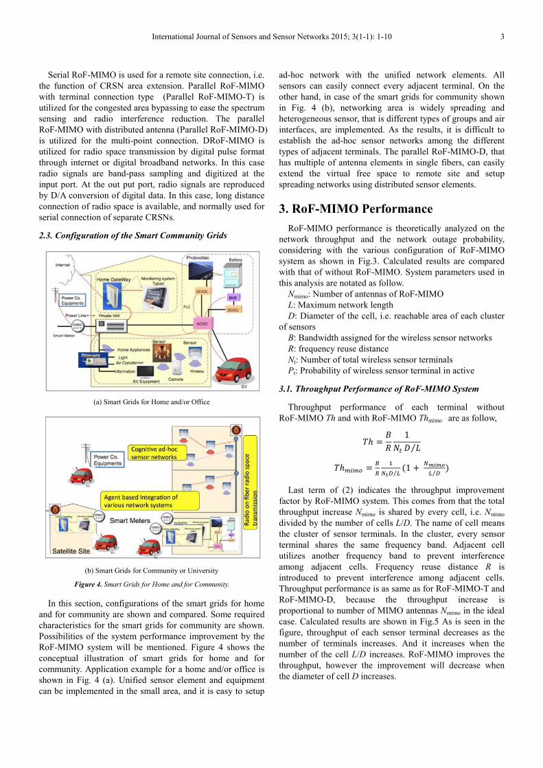
2.3. Configuration of the Smart Community Grids
(a) Smart Grids for Home and/or Office
(b) Smart Grids for Community or University
Figure 4. Smart Grids for Home and for Community.
In this section, configurations of the smart grids for home
and for community are shown and compared. Some required
characteristics for the smart grids for community are shown.
Possibilities of the system performance improvement by the
RoF-MIMO system will be mentioned. Figure 4 shows the
conceptual illustration of smart grids for home and for
community. Application example for a home and/or office is
shown in Fig. 4 (a). Unified sensor element and equipment
can be implemented in the small area, and it is easy to setup
ad-hoc network with the unified network elements. All
sensors can easily connect every adjacent terminal. On the
other hand, in case of the smart grids for community shown
in Fig. 4 (b), networking area is widely spreading and
heterogeneous sensor, that is different types of groups and air
interfaces, are implemented. As the results, it is difficult to
establish the ad-hoc sensor networks among the different
types of adjacent terminals. The parallel RoF-MIMO-D, that
has multiple of antenna elements in single fibers, can easily
extend the virtual free space to remote site and setup
spreading networks using distributed sensor elements.
3. RoF-MIMO Performance
RoF-MIMO performance is theoretically analyzed on the
network throughput and the network outage probability,
considering with the various configuration of RoF-MIMO
system as shown in Fig.3. Calculated results are compared
with that of without RoF-MIMO. System parameters used in
this analysis are notated as follow.
Nmimo: Number of antennas of RoF-MIMO
L: Maximum network length
D: Diameter of the cell, i.e. reachable area of each cluster
of sensors
B: Bandwidth assigned for the wireless sensor networks
R: frequency reuse distance
Nt: Number of total wireless sensor terminals
Pt: Probability of wireless sensor terminal in active
3.1. Throughput Performance of RoF-MIMO System
Throughput performance of each terminal without
RoF-MIMO Th and with RoF-MIMO Thmimo are as follow,
�ℎ =�
�
1
�� ⁄
�ℎ � � =�
�
�
��� �⁄(1 +
�����
� �⁄)
Last term of (2) indicates the throughput improvement
factor by RoF-MIMO system. This comes from that the total
throughput increase Nmimo is shared by every cell, i.e. Nmimo
divided by the number of cells L/D. The name of cell means
the cluster of sensor terminals. In the cluster, every sensor
terminal shares the same frequency band. Adjacent cell
utilizes another frequency band to prevent interference
among adjacent cells. Frequency reuse distance R is
introduced to prevent interference among adjacent cells.
Throughput performance is as same as for RoF-MIMO-T and
RoF-MIMO-D, because the throughput increase is
proportional to number of MIMO antennas Nmimo in the ideal
case. Calculated results are shown in Fig.5 As is seen in the
figure, throughput of each sensor terminal decreases as the
number of terminals increases. And it increases when the
number of the cell L/D increases. RoF-MIMO improves the
throughput, however the improvement will decrease when
the diameter of cell D increases.

4 Shozo Komaki et al.: Heterogeneous Cognitive Radio Sensor Networks through RoF-MIMO Technologies
Figure 5. Throughput performance of RoF-MIMO
3.2. Network Outage Rate Improvement by RoF-MIMO
Network outage happens when the link among the sensor
terminals is not reachable. In this analysis, it is assumed that
the cells are series-connected in the sensor networks, and the
network outage happens when any one of cells in the
networks does not have any sensor terminal. Network outage
probability is calculated as follows.
���� =
(1 −
��)��
����, � �!" = 2(
− 2� � � − 1)(1 −
��)��$�
����, � �!� = � � �(
� � �
− 1)(1 −
��)��$�
where, ���� , ����, � �!" and ����, � �!� denote the
network outage probability of the without RoF-MIMO, with
the RoF-MIMO-T and the RoF-MIMO-D, respectively. In this
analysis, terminal distribution is uniform in the single
dimensional space 0 through L. And it is assumed that the
probability of wireless sensor terminal in active state Pt = 1.
This means that all the sensors are power on and exist in the
area of 0 through L.
Calculated examples of network outage probability are
shown in Fig.6. As is seen in Fig.6 (a), the network outage
probability decreases as the number of terminals increases.
The RoF-MIMO system can improve the network outage
probability. Improvement factor decreases when network
length L/D becomes large. The RoF-MIMO-T is superior in
case of network length is short. The RoF-MIMO-D is superior
in case of network length is large.
Figure 6 (b) shows the calculated network outage rate vs.
network length, and it clearly shows that the ROF-MIMO-D is
better than the RoF-MIMO-T.
Figure 6 (c) shows the improvement of network outage rate
vs. number of the parallel RoF-MIMO-D stage Nmimo , i.e.
number of antennas in RoF-MIMO-D. It shows that the outage
probability is improved in proportional of Nmimo. It may be
easy to increase Nmimo in case of the RoF-MIMO-D system, by
using the optical star coupler.
(a) Network outage rate vs. Total number of terminals
(b) Network outage rate vs. normalized Network length
(c) Network outage rate and RoF-MIMO-D dimension Nmimo
Figure 6. Improvement of network outage rate by RoF-MIMO system
International Journal of Sensors and Sensor Networks 2015; 3(1-1): 1-10 5
4. Prototype System Experiments
4.1. Experimental Setup
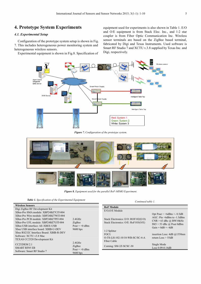
Configuration of the prototype system setup is shown in Fig.
7. This includes heterogeneous power monitoring system and
heterogeneous wireless sensors.
Experimental equipment is shown in Fig.8. Specification of
equipment used for experiments is also shown in Table 1. E/O
and O/E equipment is from Stack Elec. Inc., and 1:2 star
coupler is from Fiber Optic Communication Inc. Wireless
sensor terminals are based on the ZigBee based terminal,
fabricated by Digi and Texas Instruments. Used software is
Smart RF Studio 7 and XCTU v.3.8 supplied by Texas Inc. and
Digi, respectively.
Figure 7. Configuration of the prototype system.
Figure 8. Equipment used for the parallel RoF-MIMO Experiment.
Table 1. Specification of the Experimental Equipment
Wireless Sensors
Digi ZigBee RF Development Kit
XBee-Pro SMA module: XBP24BZ7CIT-004
XBee-Pro Wire module: XBP24BZ7WIT-004
XBee-Pro PCB module: XBP24BZ7PIT-004
XBee-Pro UFL module: XBP24BZ7UIT-004
XBee-USB interface: AE-XBEE-USB
Xbee USB interface board: XBIB-U-DEV
Xbee RS232C Interface Board: XBIB-R-DEV
Software: XCTU v3.8 Mac
2.4GHz
ZigBee
Pout = +0 dBm
9600 bps
TEXAS CC2520 Development Kit
CC2520EM 2.1
SMART RF05 EB
Software: Smart RF Studio 7
2.4GHz
ZigBee
Pout = +0 dBm
9600 bps
Continued table 1.
RoF Module
E/O,O/E Module
Stack Electronics: E/O: ROF102(E/O)
Stack Electronics: O/E: RoF103(O/E)
Opt Pout = +6dBm +- 0.5dB
AGC: Pin +6dBm to -1.5dBm
CNR > 63 dBc @ BW10kHz
IM3 > 53 dBc @ Pout 0dBm
Gain = 0dB +- 4dB
1:2 Splitter
FOCI:
O-TS-LH-102-10/10-WB-SC/SC-4-A
insertion Loss: 4dB @1550nm
return Loss > 55dB
Fiber Cable
Corning: SM-2Z-SCSC-30 Single Mode
Loss 0.09-0.14dB
6 Shozo Komaki et al.: Heterogeneous Cognitive Radio Sensor Networks through RoF-MIMO Technologies
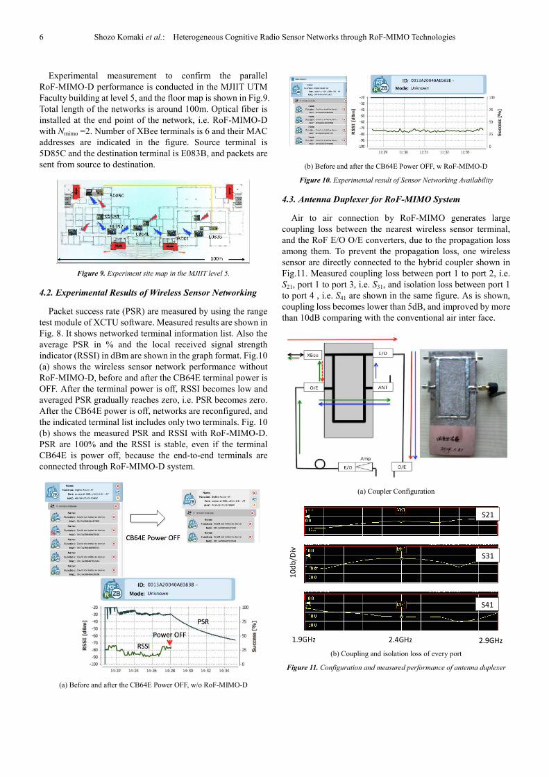
Experimental measurement to confirm the parallel
RoF-MIMO-D performance is conducted in the MJIIT UTM
Faculty building at level 5, and the floor map is shown in Fig.9.
Total length of the networks is around 100m. Optical fiber is
installed at the end point of the network, i.e. RoF-MIMO-D
with Nmimo =2. Number of XBee terminals is 6 and their MAC
addresses are indicated in the figure. Source terminal is
5D85C and the destination terminal is E083B, and packets are
sent from source to destination.
Figure 9. Experiment site map in the MJIIT level 5.
4.2. Experimental Results of Wireless Sensor Networking
Packet success rate (PSR) are measured by using the range
test module of XCTU software. Measured results are shown in
Fig. 8. It shows networked terminal information list. Also the
average PSR in % and the local received signal strength
indicator (RSSI) in dBm are shown in the graph format. Fig.10
(a) shows the wireless sensor network performance without
RoF-MIMO-D, before and after the CB64E terminal power is
OFF. After the terminal power is off, RSSI becomes low and
averaged PSR gradually reaches zero, i.e. PSR becomes zero.
After the CB64E power is off, networks are reconfigured, and
the indicated terminal list includes only two terminals. Fig. 10
(b) shows the measured PSR and RSSI with RoF-MIMO-D.
PSR are 100% and the RSSI is stable, even if the terminal
CB64E is power off, because the end-to-end terminals are
connected through RoF-MIMO-D system.
(a) Before and after the CB64E Power OFF, w/o RoF-MIMO-D
(b) Before and after the CB64E Power OFF, w RoF-MIMO-D
Figure 10. Experimental result of Sensor Networking Availability
4.3. Antenna Duplexer for RoF-MIMO System
Air to air connection by RoF-MIMO generates large
coupling loss between the nearest wireless sensor terminal,
and the RoF E/O O/E converters, due to the propagation loss
among them. To prevent the propagation loss, one wireless
sensor are directly connected to the hybrid coupler shown in
Fig.11. Measured coupling loss between port 1 to port 2, i.e.
S21, port 1 to port 3, i.e. S31, and isolation loss between port 1
to port 4 , i.e. S41 are shown in the same figure. As is shown,
coupling loss becomes lower than 5dB, and improved by more
than 10dB comparing with the conventional air inter face.
(a) Coupler Configuration
(b) Coupling and isolation loss of every port
Figure 11. Configuration and measured performance of antenna duplexer
S21
S31
S41
1.9GHz 2.4GHz 2.9GHz
10
db
/Div
International Journal of Sensors and Sensor Networks 2015; 3(1-1): 1-10 7
5. RoF-MIMO Technologies for Antenna
Multiplexing
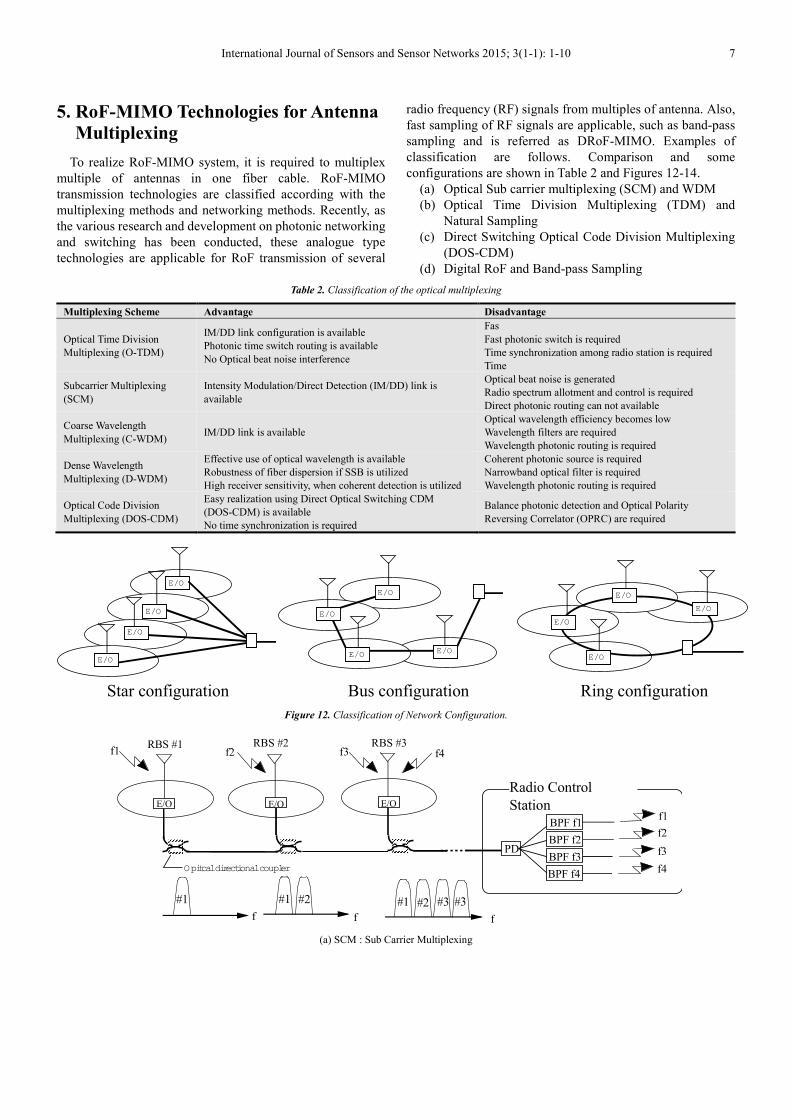
To realize RoF-MIMO system, it is required to multiplex
multiple of antennas in one fiber cable. RoF-MIMO
transmission technologies are classified according with the
multiplexing methods and networking methods. Recently, as
the various research and development on photonic networking
and switching has been conducted, these analogue type
technologies are applicable for RoF transmission of several
radio frequency (RF) signals from multiples of antenna. Also,
fast sampling of RF signals are applicable, such as band-pass
sampling and is referred as DRoF-MIMO. Examples of
classification are follows. Comparison and some
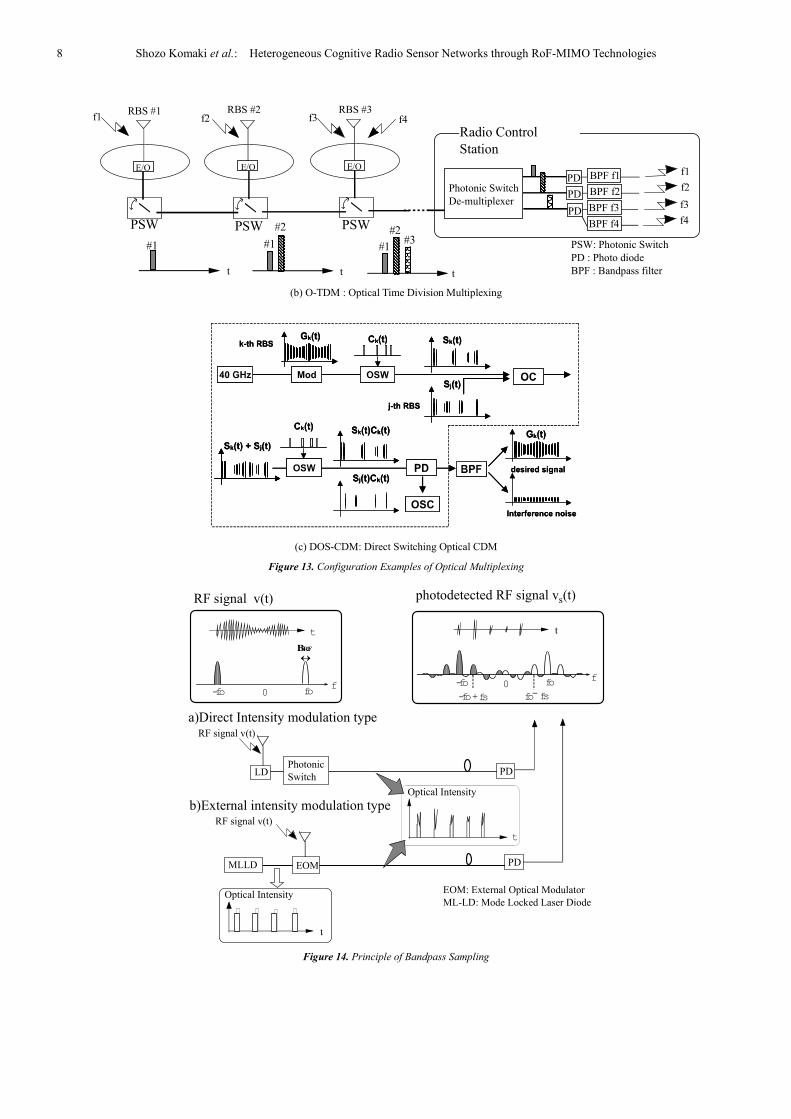
configurations are shown in Table 2 and Figures 12-14.
(a) Optical Sub carrier multiplexing (SCM) and WDM
(b) Optical Time Division Multiplexing (TDM) and
Natural Sampling
(c) Direct Switching Optical Code Division Multiplexing
(DOS-CDM)
(d) Digital RoF and Band-pass Sampling
Table 2. Classification of the optical multiplexing
Multiplexing Scheme Advantage Disadvantage
Optical Time Division
Multiplexing (O-TDM)
IM/DD link configuration is available
Photonic time switch routing is available
No Optical beat noise interference
Fas
Fast photonic switch is required
Time synchronization among radio station is required
Time
Subcarrier Multiplexing
(SCM)
Intensity Modulation/Direct Detection (IM/DD) link is
available
Optical beat noise is generated
Radio spectrum allotment and control is required
Direct photonic routing can not available
Coarse Wavelength
Multiplexing (C-WDM) IM/DD link is available
Optical wavelength efficiency becomes low
Wavelength filters are required
Wavelength photonic routing is required
Dense Wavelength
Multiplexing (D-WDM)
Effective use of optical wavelength is available
Robustness of fiber dispersion if SSB is utilized
High receiver sensitivity, when coherent detection is utilized
Coherent photonic source is required
Narrowband optical filter is required
Wavelength photonic routing is required
Optical Code Division
Multiplexing (DOS-CDM)
Easy realization using Direct Optical Switching CDM
(DOS-CDM) is available
No time synchronization is required
Balance photonic detection and Optical Polarity
Reversing Correlator (OPRC) are required
Figure 12. Classification of Network Configuration.
(a) SCM : Sub Carrier Multiplexing
E/O
Star configuration Bus configuration Ring configuration
E/O
E/O
E/O
E/O
E/O
E/O E/O
E/O
E/O
E/O
E/O
Radio Control
Station
RBS #1 RBS #2 RBS #3
#2 #3#1
f
f1 f2 f3 f4
ff
#1 #2#1 #3
PD
f4
f3
f2
f1
Opitcal directional couplerBPF f3
BPF f2
BPF f1
BPF f4
E/OE/O E/O
8 Shozo Komaki et al.: Heterogeneous Cognitive Radio Sensor Networks through RoF-MIMO Technologies
(b) O-TDM : Optical Time Division Multiplexing
(c) DOS-CDM: Direct Switching Optical CDM
Figure 13. Configuration Examples of Optical Multiplexing
Figure 14. Principle of Bandpass Sampling
RBS #1 RBS #2 RBS #3
#1
#2#3#1
#2
#1
t t t
f1 f2 f3 f4
PSW PSWPSW
PD
f4
f3
f2
f1
Photonic Switch
De-multiplexerBPF f3
BPF f2
BPF f1
BPF f4
PSW: Photonic Switch
PD : Photo diode
BPF : Bandpass filter
PD
PD
E/O E/O E/O
Radio Control
Station
t
fo-fo
fsfofs-fo+
f0
BRF
-fo fof
0
t
RF signal v(t)
a)Direct Intensity modulation type
b)External intensity modulation type
Photonic
Switch
EOM
LD
RF signal v(t)
t
Optical Intensity
MLLD
EOM: External Optical Modulator
ML-LD: Mode Locked Laser DiodeOptical Intensity
t
RF signal v(t)
PD
PD
photodetected RF signal v (t)s

International Journal of Sensors and Sensor Networks 2015; 3(1-1): 1-10 9
6. Conclusion
In this paper, RoF-MIMO application to the Smart Grids for
community is investigated and the Virtual Radio Free Space
connection of Cognitive Radio Sensor Networks is proposed.
This connection utilizes the RoF-MIMO system, and the
systems are classified into four types. Network outage
probability and the throughput performances of every type are
analyzed and calculated theoretically and compared. Results
show that the network outage probability and the system
throughput, i.e. simultaneous user capacity, can be improved
by using the parallel ROF-MIMO with distributed connection.
To confirm the theoretical result, experiments using the
prototype wireless sensor terminals are conducted in the
faculty building and confirmed that the Parallel RoF-MIMO
with distributed connection can relieve the network outage. In
the final part, various types of MIMO antenna multiplication
methods are introduced and the advantages and disadvantages
are compared.
Acknowledgements
Authors expressed their deep gratitude to Dr. Anthony
Edward Robert Centeno, MJIIT, UTM for his offer of the
ZigBee wireless sensor terminals and development kits.
Authors also expressed their gratitude to Prof. Dr. Rozhan Bin
Othman, MJIIT, UTM, and the Sumitomo Electric Corp. for
the co-operation on the community smart grid project.
References
[1] J. Mitola and G. Q. Maguire, “Cognitive radio: making software radios more personal,” IEEE personal communications, vol. 6, pp. 13-18, 1999.
[2] Hamed Al-Raweshidy, and Shozo Komaki, “Radio Over Fiber Technologies for Mobile Communication Networks,” Artech House, 2002
[3] Satbir Singh, “Simulative Radio Over Fiber Communication System,” Lambert, 2011.
[4] Jesse Russell, and Ronald Cohn, “Radio Over Fiber,” Pubmix, 2013.
[5] S. Komaki, edited, “ Wireless Agents Technology (in Japanese),” Maruzen Press., July 2008.
[6] T. Kaji, Y. Minoda, K. Tsukamoto, and S. Komaki, "Radio agent realizing user utility-based resource allocation in wireless spot access," IEEE International Symposium on ISCIT 2004, 2004, pp. 286-289 vol.1.
[7] Y. Morioka, T. Higashino, K. Tsukamoto, and S. Komaki, "Proposal of SIP based AP Selection Agent System in Wireless LAN," IEEE 18th International Symposium on PIMRC 2007, 2007, pp. 1-5.
[8] S. Komaki, "Heterogeneous cognitive radio on fiber technologies for university and/or community smart grids," IEEE 4th International Conference on ICP2013, 2013, pp. 1-4.
[9] H. Luong Hong, T. Higashino, K. Tsukamoto, and S. Komaki, "Performance improvement of radio-on-fiber ubiquitous antenna system using sub-carrier resource management," Proc. SPIE - Int. Soc. Opt. Eng. (USA). pp. 63900-1, 2006.
[10] L.H. Hai, K. Tsukamoto, and S. Komaki, “Performance Improvement of RoF Ubiquitous Antenna system using Sub-carrier Resource Management,” IEICE Trans Electron, Vol.E90-C, No.2, Feb. 2007
[11] R. Abdolee, R. Ngah, V. Vakilian, and T. A. Rahman, "Application of radio-over-fiber (ROF) in mobile communication," 2007 Asia-Pacific Conference on Applied Electromagnetics (APACE). p. 5 pp., 2007.
[12] C. A. R. Fernandes, A. Kibangou, G. Favier, and J. C. M. Mota, "Identification of nonlinear MIMO radio over fiber uplink channels," ITS '07. 2007 International Telecommunications Symposium. pp. 213-18., 2007.
[13] H. Luong Hong, T. Higashino, K. Tsukamoto, and S. Komaki, “Grouping methods for orthogonal frequency- and space-division multiple access in a radio-on-fiber radio-space transmission system,” Optical Engineering, vol. 46, no. 9, pp. 1-9, 2007.
[14] H. Seongtaek, K. Hoon, B. Kim, J. Lee, H. Lee, S. Kim, K. Song, J. Cho, and Y. Oh, "RoF system for TDD-based 44 MIMO OFDMA wireless communication systems," LEOS 2007. 20th Annual Meeting of the IEEE Lasers and Electro-Optics Society. pp. 745-6.
[15] I. Harjula, A. Ramirez, F. Martinez, D. Zorrilla, M. Katz, and V. Polo, "Practical issues in the combining of MIMO techniques and RoF in OFDM/A systems," Electronic Communications. Proceedings of the 7th WSEAS International Conference on Electronics Hardware, Wireless and Optical Communications (EHAC '08). pp. 244-8., 2007.
[16] T. Yamakami, T. Higashino, K. Tsukamoto, and S. Komaki, "An experimental investigation of applying MIMO to RoF ubiquitous antenna system," 2008 International Topical Meeting on Microwave Photonics (MWP 2008) jointly held with the 2008 Asia-Pacific Microwave Photonics Conference (APMP). pp. 201-4., 2008.
[17] M. Sauer, A. Kobyakov, and A. Ng'Oma, "Radio over fiber for picocellular network architectures," LEOS 2009 -22nd Annual Meeting of the IEEE Lasers and Electro-Optics Society. LEO 2009. pp. 675-6., 2009.
[18] I. J. G. Zuazola, J. C. Batchelor, A. Nkansah, D. Wake, and N. J. Gomes, "Microcell MIMO RoF system using low cost array antennas and improved DFB matching lines," 2009 Loughborough Antennas Propagation Conference (LAPC). pp. 373-6., 2009.
[19] A. Chowdhury, C. Hung-Chang, F. Shu-Hao, Y. Jianjun, and C. Gee-Kung, “Multi-band transport technologies for in-building host-neutral wireless over fiber access systems,” Journal of Lightwave Technology, vol. 28, no. 16, pp. 2406-15, 2010.
[20] A. Hekkala, J. Perttu, M. Lasanen, L. C. Vieira, and N. J. Gomes, "Predistortion study of radio over fibre link," 2010 Future Network Mobile Summit. p. 8 pp., 2010.
[21] T. Higashino, T. Yamakami, K. Tsukamoto, and S. Komaki, "Link quality based MIMO antenna selection in RoF ubiquitous antenna," 2010 IEEE Topical Meeting on Microwave Photonics (MWP 2010). p. 4 pp., 2010.

10 Shozo Komaki et al.: Heterogeneous Cognitive Radio Sensor Networks through RoF-MIMO Technologies
[22] K. Mitsuyama, T. Ikeda, and T. Ohtsuki, "Practical delay difference correction in distributed MIMO OFDM systems," 2010 IEEE International Conference on Wireless Information Technology and Systems (ICWITS 2010). p. 4 pp., 2010.
[23] C. A. R. Fernandes, G. Favier, and J. C. M. Mota, “PARAFAC-based channel estimation and data recovery in nonlinear MIMO spread spectrum communication systems,” Signal Processing, vol. 91, no. 2, pp. 311-22, 2011.
[24] L. Tarlazzi, P. Faccin, E. M. Vitucci, F. Fuschini, and V. Degli-Esposti, "Characterization of an interleaved F-DAS MIMO indoor propagation channel," 2010 Loughborough Antennas Propagation Conference (LAPC 2010). pp. 505-8., 2010.
[25] C.T. Lin, A. Ng’oma,. W.Y. Lee, C.C. Wei,. C.Y. Wang, T.H. Lu, J.H. Chen, W.Jr. Jiang, and C.H. Ho, “2 × 2 MIMO radio-over-fiber system at 60 GHz employing frequency domain equalization,” OPTICS EXPRESS, Vol. 20, No. 1 , January 2012
[26] S.Komaki,” Radio on Fiber Technology for Cognitive Wireless Sensor Networks ,” Proc. of ICIVE2012, Dahka, Bangladesh, pp.1-5, May 2013.
[27] T. Tashiro, K. Miyamoto, T. Iwakuni, K. Hara, Y. Fukada, J. Kani, et al., "40 km fiber transmission of time domain multiplexed MIMO RF signals for RoF-DAS over WDM-PON," in Optical Fiber Communication Conference and Exposition (OFC/NFOEC), 2012 and the National Fiber Optic Engineers Conference, pp. 1-3.
[28] G. S. D. Gordon, M. J. Crisp, R. V. Penty, and I. H. White, "Experimental investigation of antenna selection and transmit beamforming for capacity enhancement in 3X3 MIMO-enabled radio-over-fiber DAS," in Microwave Photonics (MWP), 2013 International Topical Meeting on, pp. 313-316.