HercuFlex Gear Couplings - Lovejoy, Inc. · 2019-01-16 · 4 HercuFlex Gear Couplings Gear Coupling...
28
FX Series CX Series FXL Series RA/RAHS Series The Reinvention of the Gear Coupling HercuFlex Gear Couplings
Transcript of HercuFlex Gear Couplings - Lovejoy, Inc. · 2019-01-16 · 4 HercuFlex Gear Couplings Gear Coupling...
FX Series
CX Series
FXL Series
RA/RAHS Series
The Reinvention of the Gear Coupling
HercuFlex Gear Couplings

www.lovejoy-inc.com2
When using Lovejoy products, you must follow these instructions and take the following precautions. Failure to do so may cause the power transmission product to break and parts to be thrown with sufficient force to cause severe injury or death.
Refer to this Lovejoy Catalog for proper selection, sizing, horsepower, torque range, and speed range of power transmission products, including elastomeric elements for couplings. Follow the installation instructions included with the product, and in the individual product catalogs for proper installation of power transmission products. Do not exceed catalog ratings.
During start up and operation of power transmission product, avoid sudden shock loads. Coupling assembly should operate quietly and smoothly. If coupling assembly vibrates or makes beating sound, shut down immediately, and recheck alignment. Shortly after initial operation and periodically thereafter, where applicable, inspect coupling assembly for: alignment, wear of elastomeric element, bolt torques, and flexing elements for signs of fatigue. Do not operate coupling assembly if alignment is improper, or where applicable, if elastomeric element is damaged, or worn to less than 75% of its original thickness.
Do not use any of these power transmission products for elevators, man lifts, or other devices that carry people. If the power transmission product fails, the lift device could fall resulting in severe injury or death.
For all power transmission products, you must install suitable guards in accordance with OSHA and American Society of Mechanical Engineers Standards. Do not start power transmission product before suitable guards are in place. Failure to properly guard these products may result in severe injury or death from personnel contacting moving parts or from parts being thrown from assembly in the event the power transmission product fails.
If you have any questions, contact the Lovejoy Engineering Department at 1-630-852-0500.
DisclaimerThis catalog is provided solely to give you analysis tools and data to assist you in your product selection. Product performance is affected by many factors beyond the control of Timken. Therefore, you must validate the suitability and feasibility of all product selections for your applications.
Lovejoy products are sold subject to Timken terms and conditions of sale, which include our limited warranty and remedy. Please consult with your Lovejoy engineer for more information and assistance.
Every reasonable effort has been made to ensure the accuracy of the information in this writing, but no liability is accepted for errors, omissions or for any other reason.
Safety Warning
WARNINGFailure to observe the following warnings could create a risk
of death or serious injury.
Proper maintenance and handling practices are critical. Failure to follow selection recommendations and installation instructions and to maintain proper lubrication
can result in equipment failure.
1-630-852-0500 3
Gear Coupling Selection Process ....................................................................................................4
Application Service Factors .............................................................................................................5
FX Series Couplings ....................................................................................................................... 6-7
CX Series Couplings ...................................................................................................................... 8-9
FXL Series Couplings ................................................................................................................ 10-11
Flange Interchangeability Information ................................................................................ 12-13
Additional Dimensional Data ................................................................................................. 14-15
RA and RAHS Type Rigid Adjustable Couplings ................................................................. 16-17
HercuFlex Continuous Sleeve Gear Couplings ................................................................... 18-19
HercuFlex Flanged Sleeve Gear Couplings .......................................................................... 20-21
Coupling Grease Information ....................................................................................................... 22
Application Worksheet .................................................................................................................. 23
Product Warranty ........................................................................................................................... 24
Section Page No.
Table of Contents
www.lovejoy-inc.com4
HercuFlex Gear CouplingsGear Coupling Selection Process
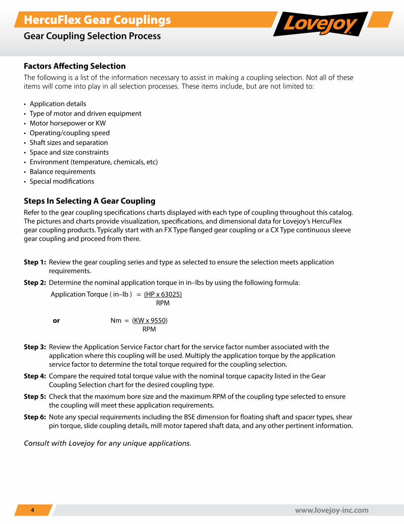
Factors Affecting SelectionThe following is a list of the information necessary to assist in making a coupling selection. Not all of these items will come into play in all selection processes. These items include, but are not limited to:
• Application details• Type of motor and driven equipment• Motor horsepower or KW• Operating/coupling speed• Shaft sizes and separation• Space and size constraints• Environment (temperature, chemicals, etc)• Balance requirements• Special modifications
Steps In Selecting A Gear CouplingRefer to the gear coupling specifications charts displayed with each type of coupling throughout this catalog. The pictures and charts provide visualization, specifications, and dimensional data for Lovejoy’s HercuFlex gear coupling products. Typically start with an FX Type flanged gear coupling or a CX Type continuous sleeve gear coupling and proceed from there.
Step 1: Review the gear coupling series and type as selected to ensure the selection meets application requirements.
Step 2: Determine the nominal application torque in in–lbs by using the following formula:
Application Torque ( in–lb ) = (HP x 63025) RPM
or Nm = (KW x 9550) RPM
Step 3: Review the Application Service Factor chart for the service factor number associated with the application where this coupling will be used. Multiply the application torque by the application service factor to determine the total torque required for the coupling selection.
Step 4: Compare the required total torque value with the nominal torque capacity listed in the Gear Coupling Selection chart for the desired coupling type.
Step 5: Check that the maximum bore size and the maximum RPM of the coupling type selected to ensure the coupling will meet these application requirements.
Step 6: Note any special requirements including the BSE dimension for floating shaft and spacer types, shear pin torque, slide coupling details, mill motor tapered shaft data, and any other pertinent information.
Consult with Lovejoy for any unique applications.
1-630-852-0500 5
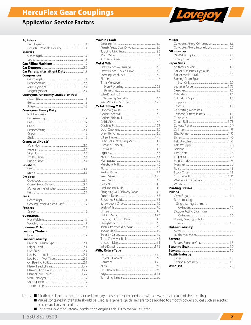
HercuFlex Gear CouplingsApplication Service Factors
Agitators Pure Liquids .................................................................... 1.0 Liquids—Variable Density...................................... 1.0Blowers Centrifugal ....................................................................... 1.0 Lobe ..................................................................................... 1.2Can Filling Machines ..................................................... 1.0Car Dumpers ........................................................................ 2.0Car Pullers, Intermittent Duty .............................. 1.5Compressors Centrifugal ....................................................................... 1.0 Reciprocating ................................................................. 2.2 Multi-Cylinder ................................................................ 2.0 Single Cylinder .............................................................. 2.0Conveyors, Uniformly Loaded or Fed Assembly .......................................................................... 1.2 Belt ........................................................................................ 1.2 Screw................................................................................... 1.2Conveyors, Heavy Duty Not Uniformly Fed Assembly ................................................................. 1.5 Belt ........................................................................................ 1.5 Oven .................................................................................... 1.5 Reciprocating ................................................................. 2.0 Screw................................................................................... 1.5 Shaker ................................................................................. 1.5Cranes and Hoists1
Main Hoists ...................................................................... 2.0 Reversing .......................................................................... 2.0 Skip Hoists........................................................................ 2.0 Trolley Drive .................................................................... 2.0 Bridge Drive .................................................................... 2.0Crushers Ore ........................................................................................ 3.0 Stone ................................................................................... 3.0Dredges Conveyors ........................................................................ 2.0 Cutter Head Drives .................................................... 2.0 Maneuvering Winches ............................................. 2.0 Pumps................................................................................. 2.0Fans Centrifugal ....................................................................... 1.0 Cooling Towers Forced Draft ................................ 1.5Feeders Screw................................................................................... 1.5Generators Not Welding .................................................................... 1.0 Welding ............................................................................. 1.5Hammer Mills ...................................................................... 2.0Laundry Washers Reversing .......................................................................... 1.5Lumber Industry Barkers—Drum Type ................................................. 2.0 Edger Feed ..................................................................... 2.0 Live Rolls ........................................................................... 2.0 Log Haul—Incline ....................................................... 2.0 Log Haul—Well Type ................................................ 2.0 Off Bearing Rolls ........................................................... 2.0 Planer Feed Chains ...................................................1.75 Planer Tilting Hoist ....................................................1.75 Planer Floor Chains ...................................................1.75 Slab Conveyor................................................................ 1.5 Sorting Table .................................................................. 1.5 Trimmer Feed ................................................................. 1.5
Machine Tools Bending Roll ................................................................... 2.0 Punch Press, Gear Driven ........................................ 2.0 Tapping Machines ...................................................... 2.0 Main Drives...................................................................... 1.5 Auxiliary Drives.............................................................. 1.5Metal Mills Draw Bench—Carriage ............................................ 2.0 Draw Bench—Main Drive ...................................... 2.0 Forming Machines ...................................................... 2.0 Slitters ................................................................................. 1.5 Table Conveyors Non-Reversing ......................................................2.25 Reversing .................................................................... 2.5 Wire Drawing & Flattening Machine ................................................ 2.0 Wire Winding Machine ..........................................1.75Metal Rolling Mills Blooming Mills ............................................................. 2.5 Coilers, hot mill ............................................................. 2.0 Coilers, cold mill ........................................................... 1.5 Cold Mills .......................................................................... 2.0 Cooling Beds ................................................................1.75 Door Openers ................................................................ 2.0 Draw Benches ................................................................ 2.0 Edger Drives..................................................................1.75 Feed Rolls, Reversing Mills ..................................... 3.5 Furnace Pushers ........................................................... 2.5 Hot Mills ............................................................................ 3.0 Ingot Cars ......................................................................... 2.5 Kick-outs ........................................................................... 2.5 Manipulators .................................................................. 3.0 Merchant Mills ............................................................... 3.0 Piercers ............................................................................... 3.0 Pusher Rams ................................................................... 2.5 Reel Drives .....................................................................1.75 Reel Drums ...................................................................... 2.0 Reelers ................................................................................ 3.0 Rod and Bar Mills ......................................................... 3.0 Roughing Mill Delivery Table ............................... 3.0 Runout Tables ................................................................ 2.5 Saws, hot & cold ........................................................... 2.5 Screwdown Drives ...................................................... 3.0 Skelp Mills ........................................................................ 3.0 Slitters ................................................................................. 3.0 Slabing Mills ..................................................................1.75 Soaking Pit Cover Drives ......................................... 3.0 Straighteners .................................................................. 2.5 Tables, transfer & runout ........................................ 2.5 Thrust Block..................................................................... 3.0 Traction Drive ................................................................. 3.0 Tube Conveyor Rolls .................................................. 2.5 Unscramblers ................................................................. 2.5 Wire Drawing ...............................................................1.75Mills, Rotary Type Ball ......................................................................................2.25 Dryers & Coolers ........................................................... 2.0 Hammer ..........................................................................1.75 Kilns ...................................................................................... 2.0 Pebble & Rod .................................................................. 2.0 Pug .....................................................................................1.75 Tumbling Barrels .......................................................... 2.0
Mixers Concrete Mixers, Continuous .............................. 1.5 Concrete Mixers, Intermittent.............................. 2.0Oil Industry Oil Well Pumping ......................................................... 2.0 Rotary Kilns ...................................................................... 2.0Paper Mills Agitators, Mixers ........................................................... 1.5 Barker Auxiliaries, Hydraulic .................................. 2.0 Barker Mechanical ....................................................... 2.0 Barking Drum Spur Gear Only ................................................................... 2.0 Beater & Pulper ...........................................................1.75 Bleacher ............................................................................. 1.0 Calenders .......................................................................... 2.0 Calenders, Super .......................................................... 1.5 Chippers ............................................................................ 2.5 Coaters ............................................................................... 1.0 Converting Machines, except Cutters, Platers .......................................... 1.5 Conveyors ........................................................................ 1.5 Couch Roll ......................................................................1.75 Cutters, Platters ............................................................. 2.0 Cylinders .........................................................................1.75 Disc Refiners .................................................................1.75 Dryers ................................................................................1.75 Felt Stretcher ................................................................1.25 Felt Whipper .................................................................. 2.0 Jordans .............................................................................1.75 Line Shaft .......................................................................... 1.5 Log Haul ............................................................................ 2.0 Pulp Grinder ..................................................................1.75 Press Roll ........................................................................... 2.0 Reel ....................................................................................... 1.5 Stock Chests ................................................................... 1.5 Suction Roll ...................................................................1.75 Washers & Thickeners ............................................... 1.5 Winders .............................................................................. 1.5Printing Presses ................................................................ 1.5Pumps Centrifugal ....................................................................... 1.0 Reciprocating Single Acting 3 or more Cylinders .................................................................... 1.5 Double Acting 2 or more Cylinders .................................................................... 2.0 Rotary, Gear Type, Lobe Vane ............................................................................... 1.5Rubber Industry Mixer .................................................................................... 2.0 Rubber Calender .......................................................... 2.0Screens Rotary, Stone or Gravel............................................. 1.5Steering Gear ...................................................................... 1.0Stokers ...................................................................................... 1.0Textile Industry Dryers .................................................................................. 1.5 Dyeing Machinery ...................................................... 1.5Windlass .................................................................................. 2.0
Notes: n 1 indicates: If people are transported, Lovejoy does not recommend and will not warranty the use of the coupling. n Values contained in the table should be used as a general guide and are to be applied to smooth power sources such as electric
motors and steam turbines. n For drives involving internal combustion engines add 1.0 to the values listed.
www.lovejoy-inc.com6
HercuFlex Gear CouplingsFX SeriesOverview
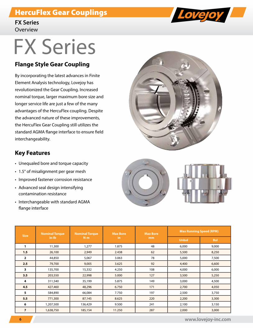
FX SeriesFlange Style Gear Coupling
By incorporating the latest advances in Finite
Element Analysis technology, Lovejoy has
revolutionized the Gear Coupling. Increased
nominal torque, larger maximum bore size and
longer service life are just a few of the many
advantages of the HercuFlex coupling. Despite
the advanced nature of these improvements,
the HercuFlex Gear Coupling still utilizes the
standard AGMA flange interface to ensure field
interchangeability.
Key Features
• Unequaled bore and torque capacity
• 1.5° of misalignment per gear mesh
• Improved fastener corrosion resistance
• Advanced seal design intensifying contamination resistance
• Interchangeable with standard AGMA flange interface
Size Nominal Torquein-lb
Nominal TorqueN-m
Max Borein
Max Boremm
Max Running Speed (RPM)
Unbal Bal
1 11,300 1,277 1.875 48 6,000 9,000
1.5 26,100 2,949 2.438 62 5,500 8,250
2 44,850 5,067 3.063 78 5,000 7,500
2.5 79,700 9,005 3.625 92 4,400 6,600
3 135,700 15,332 4.250 108 4,000 6,000
3.5 203,550 22,998 5.000 127 3,500 5,250
4 311,540 35,199 5.875 149 3,000 4,500
4.5 427,460 48,296 6.750 171 2,700 4,050
5 584,890 66,084 7.750 197 2,500 3,750
5.5 771,300 87,145 8.625 220 2,200 3,300
6 1,207,500 136,429 9.500 241 2,100 3,150
7 1,638,750 185,154 11.250 287 2,000 3,000
1-630-852-0500 7
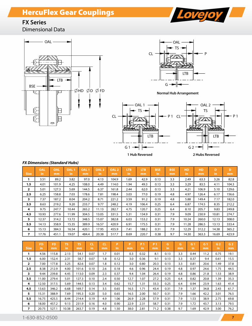
HercuFlex Gear CouplingsFX SeriesDimensional Data
OAL
BSE
LTB
HD D FD
OAL
LTB
TS
CL P
G G 1
LTB
P 1
OAL 1
TS
CL
G 2
LTB
P 1
OAL 2
TS
CL
OAL
BSE
LTB
HD D FD
OAL
LTB
TS
CL P
G G 1
LTB
P 1
OAL 1
TS
CL
G 2
LTB
P 1
OAL 2
TS
CL
OAL
BSE
LTB
HD D FD
OAL
LTB
TS
CL P
G G 1
LTB
P 1
OAL 1
TS
CL
G 2
LTB
P 1
OAL 2
TS
CL
OAL
BSE
LTB
HD D FD
OAL
LTB
TS
CL P
G G 1
LTB
P 1
OAL 1
TS
CL
G 2
LTB
P 1
OAL 2
TS
CL
Normal Hub Arrangement
1 Hub Reversed 2 Hubs Reversed
FX Dimensions (Standard Hubs)
SizeOAL
inOAL mm
OAL 1 in
OAL 1 mm
OAL 2 in
OAL 2 mm
LTB in
LTB mm
BSE in
BSE mm
HD in
HD mm
D in
D mm
1 3.51 89.2 3.82 97.0 4.13 104.9 1.69 42.9 0.13 3.3 2.49 63.3 3.26 82.8
1.5 4.01 101.9 4.25 108.0 4.49 114.0 1.94 49.3 0.13 3.3 3.29 83.5 4.11 104.3
2 5.01 127.3 5.69 144.5 6.37 161.8 2.44 62.0 0.13 3.3 4.21 106.9 5.10 129.6
2.5 6.25 158.8 7.03 178.6 7.81 198.4 3.03 77.0 0.19 4.8 4.97 126.4 6.17 156.6
3 7.37 187.2 8.04 204.2 8.71 221.2 3.59 91.2 0.19 4.8 5.88 149.4 7.17 182.0
3.5 8.63 219.2 9.20 233.7 9.77 248.2 4.19 106.4 0.25 6.4 6.87 174.5 8.35 212.2
4 9.75 247.7 10.44 265.2 11.13 282.7 4.75 120.7 0.25 6.4 8.10 205.7 9.83 249.8
4.5 10.93 277.6 11.99 304.5 13.05 331.5 5.31 134.9 0.31 7.9 9.09 230.9 10.81 274.7
5 12.37 314.2 13.72 348.5 15.07 382.8 6.03 153.2 0.31 7.9 10.24 260.0 12.13 308.0
5.5 14.13 358.9 15.35 389.9 16.57 420.9 6.91 175.5 0.31 7.9 11.28 286.5 13.13 333.4
6 15.13 384.3 16.54 420.1 17.95 455.9 7.41 188.2 0.31 7.9 12.29 312.2 14.38 365.2
7 17.76 451.1 19.07 484.4 20.38 517.7 8.69 220.7 0.38 9.7 14.30 363.3 16.69 423.9
SizeFD in
FD mm
TS in
TS mm
CL in
CL mm
P in
P mm
P 1 in
P 1 mm
G in
G mm
G 1 in
G 1 mm
G 2 in
G 2 mm
1 4.56 115.8 2.13 54.1 0.07 1.7 0.01 0.3 0.32 8.1 0.13 3.3 0.44 11.2 0.75 19.1
1.5 6.00 152.4 2.31 58.7 0.07 1.8 0.12 3.0 0.36 9.1 0.13 3.3 0.37 9.4 0.61 15.5
2 7.00 177.8 3.25 82.6 0.07 1.8 0.12 3.0 0.80 20.3 0.13 3.3 0.81 20.6 1.49 37.8
2.5 8.38 212.9 4.00 101.6 0.10 2.6 0.18 4.6 0.96 24.4 0.19 4.8 0.97 24.6 1.75 44.5
3 9.44 239.8 4.45 113.0 0.09 2.3 0.37 9.4 1.04 26.4 0.19 4.8 0.86 21.8 1.53 38.9
3.5 11.00 279.4 5.01 127.3 0.10 2.4 0.50 12.7 1.07 27.2 0.25 6.4 0.82 20.8 1.39 35.3
4 12.50 317.5 5.69 144.5 0.13 3.4 0.62 15.7 1.31 33.3 0.25 6.4 0.94 23.9 1.63 41.4
4.5 13.63 346.2 6.68 169.7 0.14 3.5 0.65 16.5 1.71 43.4 0.31 7.9 1.37 34.8 2.43 61.7
5 15.31 388.9 7.69 195.3 0.20 5.0 0.65 16.5 2.00 50.7 0.31 7.9 1.66 42.2 3.01 76.5
5.5 16.75 425.5 8.44 214.4 0.19 4.9 1.06 26.9 2.28 57.9 0.31 7.9 1.53 38.9 2.75 69.8
6 18.00 457.2 9.13 231.9 0.16 4.0 0.90 22.9 2.31 58.7 0.31 7.9 1.72 43.7 3.13 79.5
7 20.75 527.1 10.38 263.7 0.19 4.8 1.50 38.0 2.81 71.2 0.38 9.7 1.69 42.9 3.00 76.2
www.lovejoy-inc.com8
HercuFlex Gear CouplingsCX SeriesOverview
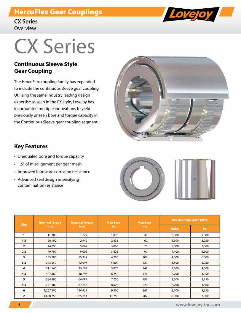
CX SeriesContinuous Sleeve Style Gear Coupling
The HercuFlex coupling family has expanded
to include the continuous sleeve gear coupling.
Utilizing the same industry leading design
expertise as seen in the FX style, Lovejoy has
incorporated multiple innovations to yield
previously unseen bore and torque capacity in
the Continuous Sleeve gear coupling segment.
Key Features
• Unequaled bore and torque capacity
• 1.5° of misalignment per gear mesh
• Improved hardware corrosion resistance
• Advanced seal design intensifying contamination resistance
Size Nominal Torquein-lb
Nominal TorqueN-m
Max Borein
Max Boremm
Max Running Speed (RPM)
Unbal Bal
1 11,300 1,277 1.875 48 6,000 9,000
1.5 26,100 2,949 2.438 62 5,500 8,250
2 44,850 5,067 3.063 78 5,000 7,500
2.5 79,700 9,005 3.625 92 4,400 6,600
3 135,700 15,332 4.250 108 4,000 6,000
3.5 203,550 22,998 5.000 127 3,500 5,250
4 311,540 35,199 5.875 149 3,000 4,500
4.5 427,460 48,296 6.750 171 2,700 4,050
5 584,890 66,084 7.750 197 2,500 3,750
5.5 771,300 87,145 8.625 220 2,200 3,300
6 1,207,500 136,429 9.500 241 2,100 3,150
7 1,638,750 185,154 11.250 287 2,000 3,000
1-630-852-0500 9
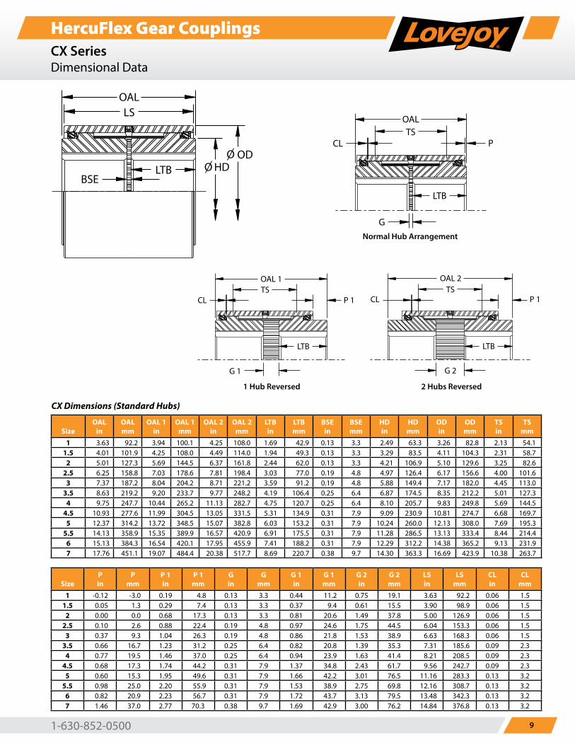
HercuFlex Gear CouplingsCX SeriesDimensional Data
OALLS
BSELTB HD
ODOO
OALTS
OAL 1TS
OAL 2TS
CL
G
G 1 G 2
CL CL
LTB LTB
P 1 P 1
LTB
P
OALLS
BSELTB HD
ODOO
OALTS
OAL 1TS
OAL 2TS
CL
G
G 1 G 2
CL CL
LTB LTB
P 1 P 1
LTB
P
OALLS
BSELTB HD
ODOO
OALTS
OAL 1TS
OAL 2TS
CL
G
G 1 G 2
CL CL
LTB LTB
P 1 P 1
LTB
P
OALLS
BSELTB HD
ODOO
OALTS
OAL 1TS
OAL 2TS
CL
G
G 1 G 2
CL CL
LTB LTB
P 1 P 1
LTB
P
Normal Hub Arrangement
1 Hub Reversed 2 Hubs Reversed
CX Dimensions (Standard Hubs)
SizeOAL
inOAL mm
OAL 1 in
OAL 1 mm
OAL 2 in
OAL 2 mm
LTB in
LTB mm
BSE in
BSE mm
HD in
HD mm
OD in
OD mm
TS in
TS mm
1 3.63 92.2 3.94 100.1 4.25 108.0 1.69 42.9 0.13 3.3 2.49 63.3 3.26 82.8 2.13 54.11.5 4.01 101.9 4.25 108.0 4.49 114.0 1.94 49.3 0.13 3.3 3.29 83.5 4.11 104.3 2.31 58.7
2 5.01 127.3 5.69 144.5 6.37 161.8 2.44 62.0 0.13 3.3 4.21 106.9 5.10 129.6 3.25 82.62.5 6.25 158.8 7.03 178.6 7.81 198.4 3.03 77.0 0.19 4.8 4.97 126.4 6.17 156.6 4.00 101.6
3 7.37 187.2 8.04 204.2 8.71 221.2 3.59 91.2 0.19 4.8 5.88 149.4 7.17 182.0 4.45 113.03.5 8.63 219.2 9.20 233.7 9.77 248.2 4.19 106.4 0.25 6.4 6.87 174.5 8.35 212.2 5.01 127.3
4 9.75 247.7 10.44 265.2 11.13 282.7 4.75 120.7 0.25 6.4 8.10 205.7 9.83 249.8 5.69 144.54.5 10.93 277.6 11.99 304.5 13.05 331.5 5.31 134.9 0.31 7.9 9.09 230.9 10.81 274.7 6.68 169.7
5 12.37 314.2 13.72 348.5 15.07 382.8 6.03 153.2 0.31 7.9 10.24 260.0 12.13 308.0 7.69 195.35.5 14.13 358.9 15.35 389.9 16.57 420.9 6.91 175.5 0.31 7.9 11.28 286.5 13.13 333.4 8.44 214.4
6 15.13 384.3 16.54 420.1 17.95 455.9 7.41 188.2 0.31 7.9 12.29 312.2 14.38 365.2 9.13 231.97 17.76 451.1 19.07 484.4 20.38 517.7 8.69 220.7 0.38 9.7 14.30 363.3 16.69 423.9 10.38 263.7
SizeP in
P mm
P 1 in
P 1 mm
G in
G mm
G 1 in
G 1 mm
G 2 in
G 2 mm
LS in
LS mm
CL in
CL mm
1 -0.12 -3.0 0.19 4.8 0.13 3.3 0.44 11.2 0.75 19.1 3.63 92.2 0.06 1.51.5 0.05 1.3 0.29 7.4 0.13 3.3 0.37 9.4 0.61 15.5 3.90 98.9 0.06 1.5
2 0.00 0.0 0.68 17.3 0.13 3.3 0.81 20.6 1.49 37.8 5.00 126.9 0.06 1.52.5 0.10 2.6 0.88 22.4 0.19 4.8 0.97 24.6 1.75 44.5 6.04 153.3 0.06 1.5
3 0.37 9.3 1.04 26.3 0.19 4.8 0.86 21.8 1.53 38.9 6.63 168.3 0.06 1.53.5 0.66 16.7 1.23 31.2 0.25 6.4 0.82 20.8 1.39 35.3 7.31 185.6 0.09 2.3
4 0.77 19.5 1.46 37.0 0.25 6.4 0.94 23.9 1.63 41.4 8.21 208.5 0.09 2.34.5 0.68 17.3 1.74 44.2 0.31 7.9 1.37 34.8 2.43 61.7 9.56 242.7 0.09 2.3
5 0.60 15.3 1.95 49.6 0.31 7.9 1.66 42.2 3.01 76.5 11.16 283.3 0.13 3.25.5 0.98 25.0 2.20 55.9 0.31 7.9 1.53 38.9 2.75 69.8 12.16 308.7 0.13 3.2
6 0.82 20.9 2.23 56.7 0.31 7.9 1.72 43.7 3.13 79.5 13.48 342.3 0.13 3.27 1.46 37.0 2.77 70.3 0.38 9.7 1.69 42.9 3.00 76.2 14.84 376.8 0.13 3.2
www.lovejoy-inc.com10
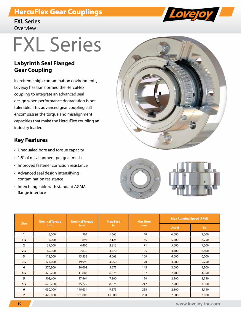
HercuFlex Gear CouplingsFXL SeriesOverview
Size Nominal Torquein-lb
Nominal TorqueN-m
Max Borein
Max Boremm
Max Running Speed (RPM)
Unbal Bal
1 8,000 904 1.563 40 6,000 9,000
1.5 15,000 1,695 2.125 55 5,500 8,250
2 39,000 4,406 2.813 71 5,000 7,500
2.5 69,300 7,830 3.370 85 4,400 6,600
3 118,000 13,332 4.063 100 4,000 6,000
3.5 177,000 19,998 4.750 120 3,500 5,250
4 270,900 30,608 5.675 145 3,000 4,500
4.5 370,700 41,883 6.375 167 2,700 4,050
5 508,600 57,464 7.500 190 2,500 3,750
5.5 670,700 75,779 8.375 212 2,200 3,300
6 1,050,000 118,634 9.375 238 2,100 3,150
7 1,425,000 161,003 11.000 280 2,000 3,000
FXL SeriesLabyrinth Seal Flanged Gear Coupling
In extreme high contamination environments,
Lovejoy has transformed the HercuFlex
coupling to integrate an advanced seal
design when performance degradation is not
tolerable. This advanced gear coupling still
encompasses the torque and misalignment
capacities that make the HercuFlex coupling an
industry leader.
Key Features
• Unequaled bore and torque capacity
• 1.5° of misalignment per gear mesh
• Improved fastener corrosion resistance
• Advanced seal design intensifying contamination resistance
• Interchangeable with standard AGMA flange interface
1-630-852-0500 11
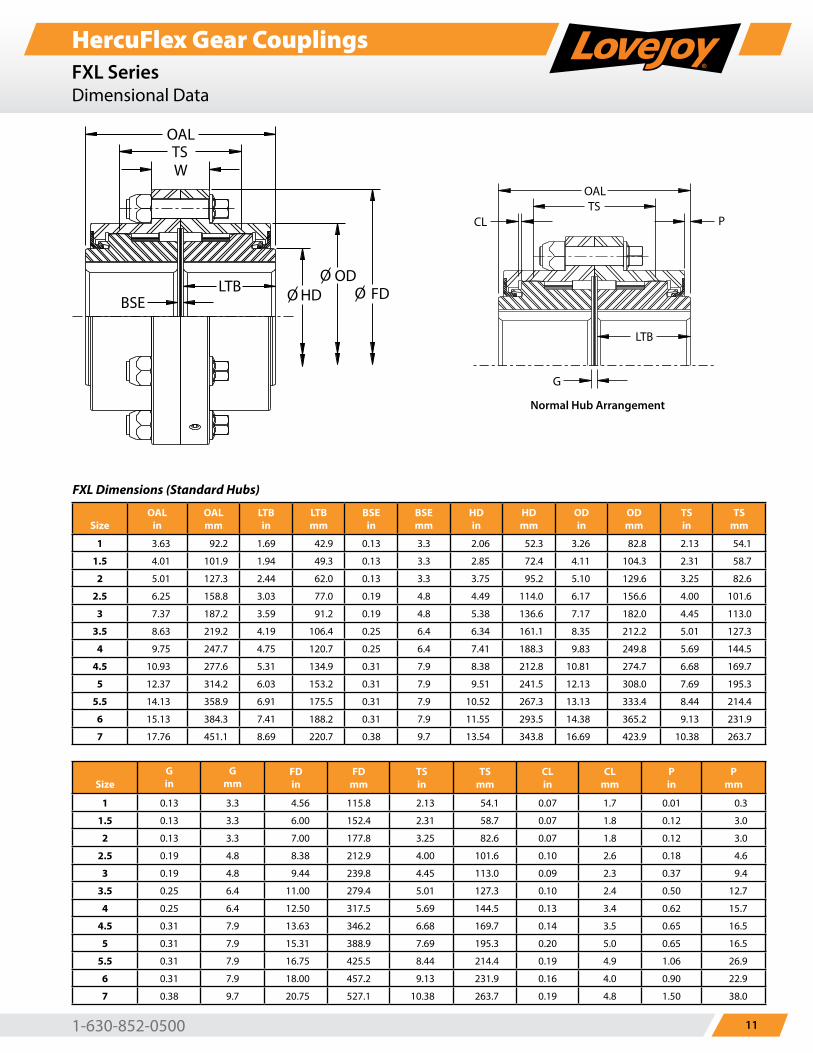
HercuFlex Gear CouplingsFXL SeriesDimensional Data
FXL Dimensions (Standard Hubs)
SizeOAL
inOAL mm
LTB in
LTB mm
BSE in
BSE mm
HD in
HD mm
OD in
OD mm
TS in
TS mm
1 3.63 92.2 1.69 42.9 0.13 3.3 2.06 52.3 3.26 82.8 2.13 54.1
1.5 4.01 101.9 1.94 49.3 0.13 3.3 2.85 72.4 4.11 104.3 2.31 58.7
2 5.01 127.3 2.44 62.0 0.13 3.3 3.75 95.2 5.10 129.6 3.25 82.6
2.5 6.25 158.8 3.03 77.0 0.19 4.8 4.49 114.0 6.17 156.6 4.00 101.6
3 7.37 187.2 3.59 91.2 0.19 4.8 5.38 136.6 7.17 182.0 4.45 113.0
3.5 8.63 219.2 4.19 106.4 0.25 6.4 6.34 161.1 8.35 212.2 5.01 127.3
4 9.75 247.7 4.75 120.7 0.25 6.4 7.41 188.3 9.83 249.8 5.69 144.5
4.5 10.93 277.6 5.31 134.9 0.31 7.9 8.38 212.8 10.81 274.7 6.68 169.7
5 12.37 314.2 6.03 153.2 0.31 7.9 9.51 241.5 12.13 308.0 7.69 195.3
5.5 14.13 358.9 6.91 175.5 0.31 7.9 10.52 267.3 13.13 333.4 8.44 214.4
6 15.13 384.3 7.41 188.2 0.31 7.9 11.55 293.5 14.38 365.2 9.13 231.9
7 17.76 451.1 8.69 220.7 0.38 9.7 13.54 343.8 16.69 423.9 10.38 263.7
OAL
LTB
G
TSCL P
OALTS
BSE
W
LTBODO
FDOHDO
OALTS
OAL 1TS
OAL 2TS
CL
G
G 1 G 2
CL CL
LTB LTB
P 1 P 1
LTB
P
THESE ARE THE CX DRAWINGSSTILL NEED THE FXL NORMAL, 1 HUB AND 2 HUB REVERSED
THESE ARE THE CX DRAWINGSSTILL NEED THE FXL NORMAL, 1 HUB AND 2 HUB REVERSED
THESE ARE THE CX DRAWINGSSTILL NEED THE FXL NORMAL, 1 HUB AND 2 HUB REVERSED
Normal Hub Arrangement
SizeG in
G mm
FD in
FD mm
TS in
TS mm
CL in
CL mm
P in
P mm
1 0.13 3.3 4.56 115.8 2.13 54.1 0.07 1.7 0.01 0.3
1.5 0.13 3.3 6.00 152.4 2.31 58.7 0.07 1.8 0.12 3.0
2 0.13 3.3 7.00 177.8 3.25 82.6 0.07 1.8 0.12 3.0
2.5 0.19 4.8 8.38 212.9 4.00 101.6 0.10 2.6 0.18 4.6
3 0.19 4.8 9.44 239.8 4.45 113.0 0.09 2.3 0.37 9.4
3.5 0.25 6.4 11.00 279.4 5.01 127.3 0.10 2.4 0.50 12.7
4 0.25 6.4 12.50 317.5 5.69 144.5 0.13 3.4 0.62 15.7
4.5 0.31 7.9 13.63 346.2 6.68 169.7 0.14 3.5 0.65 16.5
5 0.31 7.9 15.31 388.9 7.69 195.3 0.20 5.0 0.65 16.5
5.5 0.31 7.9 16.75 425.5 8.44 214.4 0.19 4.9 1.06 26.9
6 0.31 7.9 18.00 457.2 9.13 231.9 0.16 4.0 0.90 22.9
7 0.38 9.7 20.75 527.1 10.38 263.7 0.19 4.8 1.50 38.0
www.lovejoy-inc.com12
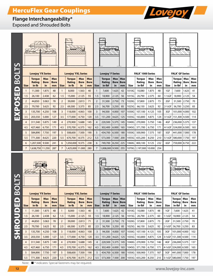
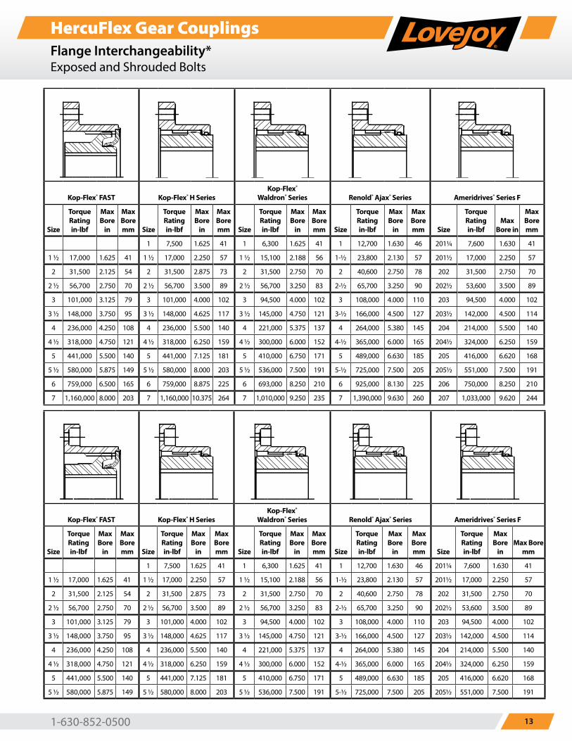
HercuFlex Gear CouplingsFlange Interchangeability*Exposed and Shrouded Bolts
EXPO
SED
BO
LTS
Lovejoy® FX Series Lovejoy® FXL Series Lovejoy® F Series FALK® 1000 Series FALK® GF Series Kop-Flex® FAST Kop-Flex® H SeriesKop-Flex®
Waldron® Series Renold® Ajax® Series Ameridrives® Series F
Size
Torque Rating
in-lb
Max Bore
in
Max Bore mm Size
Torque Rating
in-lb
Max Bore
in
Max Bore mm Size
Torque Rating in-lbf
Max Bore
in
Max Bore mm Size
Torque Rating in-lbf
Max Bore
in
Max Bore mm Size
Torque Rating in-lbf
Max Bore
in
Max Bore mm Size
Torque Rating in-lbf
Max Bore
in
Max Bore mm Size
Torque Rating in-lbf
Max Bore
in
Max Bore mm Size
Torque Rating in-lbf
Max Bore
in
Max Bore mm Size
Torque Rating in-lbf
Max Bore
in
Max Bore mm Size
Torque Rating in-lbf
Max Bore in
Max Bore mm
1 11,300 1.875 48 1 8,000 1.563 40 1 7,600 1.625 42 1010G 10,080 1.875 48 1GF 7,600 1.625 41 1 7,500 1.625 41 1 6,300 1.625 41 1 12,700 1.630 46 201¼ 7,600 1.630 41
1.5 26,100 2.438 62 1.5 15,000 2.125 55 1.5 18,900 2.125 56 1015G 20,790 2.375 60 1-½GF 18,900 2.125 54 1 ½ 17,000 1.625 41 1 ½ 17,000 2.250 57 1 ½ 15,100 2.188 56 1-½ 23,800 2.130 57 201½ 17,000 2.250 57
2 44,850 3.063 78 2 39,000 2.813 71 2 31,500 2.750 73 1020G 37,800 2.875 73 2GF 31,500 2.750 70 2 31,500 2.125 54 2 31,500 2.875 73 2 31,500 2.750 70 2 40,600 2.750 78 202 31,500 2.750 70
2.5 79,700 3.625 92 2.5 69,300 3.375 85 2.5 56,700 3.250 85 1025G 66,150 3.625 92 2-½GF 56,700 3.250 83 2 ½ 56,700 2.750 70 2 ½ 56,700 3.500 89 2 ½ 56,700 3.250 83 2-½ 65,700 3.250 90 202½ 53,600 3.500 89
3 135,700 4.250 108 3 118,000 4.063 100 3 94,500 4.000 107 1030G 107,100 4.125 105 3GF 101,000 4.000 102 3 101,000 3.125 79 3 101,000 4.000 102 3 94,500 4.000 102 3 108,000 4.000 110 203 94,500 4.000 102
3.5 203,550 5.000 127 3.5 177,000 4.750 120 3.5 151,200 4.625 125 1035G 163,800 4.875 124 3-½GF 151,300 4.500 114 3 ½ 148,000 3.750 95 3 ½ 148,000 4.625 117 3 ½ 145,000 4.750 121 3-½ 166,000 4.500 127 203½ 142,000 4.500 114
4 311,540 5.875 149 4 270,900 5.688 145 4 220,500 5.375 145 1040G 270,900 5.750 146 4GF 236,000 5.375 137 4 236,000 4.250 108 4 236,000 5.500 140 4 221,000 5.375 137 4 264,000 5.380 145 204 214,000 5.500 140
4.5 427,460 6.750 171 4.5 370,700 6.375 162 4.5 302,400 6.000 165 1045G 371,700 6.750 171 4-½GF 324,000 6.500 165 4 ½ 318,000 4.750 121 4 ½ 318,000 6.250 159 4 ½ 300,000 6.000 152 4-½ 365,000 6.000 165 204½ 324,000 6.250 159
5 584,890 7.750 197 5 508,600 7.500 190 5 434,700 6.500 180 1050G 500,900 7.375 187 5GF 441,000 7.000 178 5 441,000 5.500 140 5 441,000 7.125 181 5 410,000 6.750 171 5 489,000 6.630 185 205 416,000 6.620 168
5.5 771,300 8.625 220 5.5 670,700 8.375 212 5.5 573,300 7.500 200 1055G 655,200 8.250 210 5-½GF 580,000 7.750 197 5 ½ 580,000 5.875 149 5 ½ 580,000 8.000 203 5 ½ 536,000 7.500 191 5-½ 725,000 7.500 205 205½ 551,000 7.500 191
6 1,207,500 9.500 241 6 1,050,000 9.375 238 6 749,700 8.250 225 1060G 800,100 9.125 232 6GF 759,000 8.750 222 6 759,000 6.500 165 6 759,000 8.875 225 6 693,000 8.250 210 6 925,000 8.130 225 206 750,000 8.250 210
7 1,638,750 11.250 287 7 1,425,000 11.000 280 7 1,008,000 9.500 255 1070G 1,197,000 10.000 254 7 1,160,000 8.000 203 7 1,160,000 10.375 264 7 1,010,000 9.250 235 7 1,390,000 9.630 260 207 1,033,000 9.620 244
SHRO
UD
ED B
OLT
S
Lovejoy® FX Series Lovejoy® FXL Series Lovejoy® F Series FALK® 1000 Series FALK® GF Series Kop-Flex® FAST Kop-Flex® H SeriesKop-Flex®
Waldron® Series Renold® Ajax® Series Ameridrives® Series F
Size
Torque Rating
in-lb
Max Bore
in
Max Bore mm Size
Torque Rating
in-lb
Max Bore
in
Max Bore mm Size
Torque Rating in-lbf
Max Bore
in
Max Bore mm Size
Torque Rating in-lbf
Max Bore
in
Max Bore mm Size
Torque Rating in-lbf
Max Bore
in
Max Bore mm Size
Torque Rating in-lbf
Max Bore
in
Max Bore mm Size
Torque Rating in-lbf
Max Bore
in
Max Bore mm Size
Torque Rating in-lbf
Max Bore
in
Max Bore mm Size
Torque Rating in-lbf
Max Bore
in
Max Bore mm Size
Torque Rating in-lbf
Max Bore
inMax Bore
mm
1 11,300 1.875 48 1 8,000 1.563 40 1 7,600 1.625 42 1010G 10,080 1.875 48 1GF 7,600 1.625 41 1 7,500 1.625 41 1 6,300 1.625 41 1 12,700 1.630 46 201¼ 7,600 1.630 41
1.5 26,100 2.438 62 1.5 15,000 2.125 55 1.5 18,900 2.125 56 1015G 20,790 2.375 60 1-½GF 18,900 2.125 54 1 ½ 17,000 1.625 41 1 ½ 17,000 2.250 57 1 ½ 15,100 2.188 56 1-½ 23,800 2.130 57 201½ 17,000 2.250 57
2 44,850 3.063 78 2 39,000 2.813 71 2 31,500 2.750 73 1020G 37,800 2.875 73 2GF 31,500 2.750 70 2 31,500 2.125 54 2 31,500 2.875 73 2 31,500 2.750 70 2 40,600 2.750 78 202 31,500 2.750 70
2.5 79,700 3.625 92 2.5 69,300 3.375 85 2.5 56,700 3.250 85 1025G 66,150 3.625 92 2-½GF 56,700 3.250 83 2 ½ 56,700 2.750 70 2 ½ 56,700 3.500 89 2 ½ 56,700 3.250 83 2-½ 65,700 3.250 90 202½ 53,600 3.500 89
3 135,700 4.250 108 3 118,000 4.063 100 3 94,500 4.000 107 1030G 107,100 4.125 105 3GF 101,000 4.000 102 3 101,000 3.125 79 3 101,000 4.000 102 3 94,500 4.000 102 3 108,000 4.000 110 203 94,500 4.000 102
3.5 203,550 5.000 127 3.5 177,000 4.750 120 3.5 151,200 4.625 125 1035G 163,800 4.875 124 3-½GF 151,300 4.500 114 3 ½ 148,000 3.750 95 3 ½ 148,000 4.625 117 3 ½ 145,000 4.750 121 3-½ 166,000 4.500 127 203½ 142,000 4.500 114
4 311,540 5.875 149 4 270,900 5.688 145 4 220,500 5.375 145 1040G 270,900 5.750 146 4GF 236,000 5.375 137 4 236,000 4.250 108 4 236,000 5.500 140 4 221,000 5.375 137 4 264,000 5.380 145 204 214,000 5.500 140
4.5 427,460 6.750 171 4.5 370,700 6.375 162 4.5 302,400 6.000 165 1045G 371,700 6.750 171 4-½GF 324,000 6.500 165 4 ½ 318,000 4.750 121 4 ½ 318,000 6.250 159 4 ½ 300,000 6.000 152 4-½ 365,000 6.000 165 204½ 324,000 6.250 159
5 584,890 7.750 197 5 508,600 7.500 190 5 434,700 6.500 180 1050G 500,900 7.375 187 5GF 441,000 7.000 178 5 441,000 5.500 140 5 441,000 7.125 181 5 410,000 6.750 171 5 489,000 6.630 185 205 416,000 6.620 168
5.5 771,300 8.625 220 5.5 670,700 8.375 212 5.5 573,300 7.500 200 1055G 655,200 8.250 210 5-½GF 580,000 7.750 197 5 ½ 580,000 5.875 149 5 ½ 580,000 8.000 203 5 ½ 536,000 7.500 191 5-½ 725,000 7.500 205 205½ 551,000 7.500 191
Note: n * indicates: Special fasteners may be required.
1-630-852-0500 13
HercuFlex Gear CouplingsFlange Interchangeability*Exposed and Shrouded Bolts
EXPO
SED
BO
LTS
Lovejoy® FX Series Lovejoy® FXL Series Lovejoy® F Series FALK® 1000 Series FALK® GF Series Kop-Flex® FAST Kop-Flex® H SeriesKop-Flex®
Waldron® Series Renold® Ajax® Series Ameridrives® Series F
Size
Torque Rating
in-lb
Max Bore
in
Max Bore mm Size
Torque Rating
in-lb
Max Bore
in
Max Bore mm Size
Torque Rating in-lbf
Max Bore
in
Max Bore mm Size
Torque Rating in-lbf
Max Bore
in
Max Bore mm Size
Torque Rating in-lbf
Max Bore
in
Max Bore mm Size
Torque Rating in-lbf
Max Bore
in
Max Bore mm Size
Torque Rating in-lbf
Max Bore
in
Max Bore mm Size
Torque Rating in-lbf
Max Bore
in
Max Bore mm Size
Torque Rating in-lbf
Max Bore
in
Max Bore mm Size
Torque Rating in-lbf
Max Bore in
Max Bore mm
1 11,300 1.875 48 1 8,000 1.563 40 1 7,600 1.625 42 1010G 10,080 1.875 48 1GF 7,600 1.625 41 1 7,500 1.625 41 1 6,300 1.625 41 1 12,700 1.630 46 201¼ 7,600 1.630 41
1.5 26,100 2.438 62 1.5 15,000 2.125 55 1.5 18,900 2.125 56 1015G 20,790 2.375 60 1-½GF 18,900 2.125 54 1 ½ 17,000 1.625 41 1 ½ 17,000 2.250 57 1 ½ 15,100 2.188 56 1-½ 23,800 2.130 57 201½ 17,000 2.250 57
2 44,850 3.063 78 2 39,000 2.813 71 2 31,500 2.750 73 1020G 37,800 2.875 73 2GF 31,500 2.750 70 2 31,500 2.125 54 2 31,500 2.875 73 2 31,500 2.750 70 2 40,600 2.750 78 202 31,500 2.750 70
2.5 79,700 3.625 92 2.5 69,300 3.375 85 2.5 56,700 3.250 85 1025G 66,150 3.625 92 2-½GF 56,700 3.250 83 2 ½ 56,700 2.750 70 2 ½ 56,700 3.500 89 2 ½ 56,700 3.250 83 2-½ 65,700 3.250 90 202½ 53,600 3.500 89
3 135,700 4.250 108 3 118,000 4.063 100 3 94,500 4.000 107 1030G 107,100 4.125 105 3GF 101,000 4.000 102 3 101,000 3.125 79 3 101,000 4.000 102 3 94,500 4.000 102 3 108,000 4.000 110 203 94,500 4.000 102
3.5 203,550 5.000 127 3.5 177,000 4.750 120 3.5 151,200 4.625 125 1035G 163,800 4.875 124 3-½GF 151,300 4.500 114 3 ½ 148,000 3.750 95 3 ½ 148,000 4.625 117 3 ½ 145,000 4.750 121 3-½ 166,000 4.500 127 203½ 142,000 4.500 114
4 311,540 5.875 149 4 270,900 5.688 145 4 220,500 5.375 145 1040G 270,900 5.750 146 4GF 236,000 5.375 137 4 236,000 4.250 108 4 236,000 5.500 140 4 221,000 5.375 137 4 264,000 5.380 145 204 214,000 5.500 140
4.5 427,460 6.750 171 4.5 370,700 6.375 162 4.5 302,400 6.000 165 1045G 371,700 6.750 171 4-½GF 324,000 6.500 165 4 ½ 318,000 4.750 121 4 ½ 318,000 6.250 159 4 ½ 300,000 6.000 152 4-½ 365,000 6.000 165 204½ 324,000 6.250 159
5 584,890 7.750 197 5 508,600 7.500 190 5 434,700 6.500 180 1050G 500,900 7.375 187 5GF 441,000 7.000 178 5 441,000 5.500 140 5 441,000 7.125 181 5 410,000 6.750 171 5 489,000 6.630 185 205 416,000 6.620 168
5.5 771,300 8.625 220 5.5 670,700 8.375 212 5.5 573,300 7.500 200 1055G 655,200 8.250 210 5-½GF 580,000 7.750 197 5 ½ 580,000 5.875 149 5 ½ 580,000 8.000 203 5 ½ 536,000 7.500 191 5-½ 725,000 7.500 205 205½ 551,000 7.500 191
6 1,207,500 9.500 241 6 1,050,000 9.375 238 6 749,700 8.250 225 1060G 800,100 9.125 232 6GF 759,000 8.750 222 6 759,000 6.500 165 6 759,000 8.875 225 6 693,000 8.250 210 6 925,000 8.130 225 206 750,000 8.250 210
7 1,638,750 11.250 287 7 1,425,000 11.000 280 7 1,008,000 9.500 255 1070G 1,197,000 10.000 254 7 1,160,000 8.000 203 7 1,160,000 10.375 264 7 1,010,000 9.250 235 7 1,390,000 9.630 260 207 1,033,000 9.620 244
SHRO
UD
ED B
OLT
S
Lovejoy® FX Series Lovejoy® FXL Series Lovejoy® F Series FALK® 1000 Series FALK® GF Series Kop-Flex® FAST Kop-Flex® H SeriesKop-Flex®
Waldron® Series Renold® Ajax® Series Ameridrives® Series F
Size
Torque Rating
in-lb
Max Bore
in
Max Bore mm Size
Torque Rating
in-lb
Max Bore
in
Max Bore mm Size
Torque Rating in-lbf
Max Bore
in
Max Bore mm Size
Torque Rating in-lbf
Max Bore
in
Max Bore mm Size
Torque Rating in-lbf
Max Bore
in
Max Bore mm Size
Torque Rating in-lbf
Max Bore
in
Max Bore mm Size
Torque Rating in-lbf
Max Bore
in
Max Bore mm Size
Torque Rating in-lbf
Max Bore
in
Max Bore mm Size
Torque Rating in-lbf
Max Bore
in
Max Bore mm Size
Torque Rating in-lbf
Max Bore
inMax Bore
mm
1 11,300 1.875 48 1 8,000 1.563 40 1 7,600 1.625 42 1010G 10,080 1.875 48 1GF 7,600 1.625 41 1 7,500 1.625 41 1 6,300 1.625 41 1 12,700 1.630 46 201¼ 7,600 1.630 41
1.5 26,100 2.438 62 1.5 15,000 2.125 55 1.5 18,900 2.125 56 1015G 20,790 2.375 60 1-½GF 18,900 2.125 54 1 ½ 17,000 1.625 41 1 ½ 17,000 2.250 57 1 ½ 15,100 2.188 56 1-½ 23,800 2.130 57 201½ 17,000 2.250 57
2 44,850 3.063 78 2 39,000 2.813 71 2 31,500 2.750 73 1020G 37,800 2.875 73 2GF 31,500 2.750 70 2 31,500 2.125 54 2 31,500 2.875 73 2 31,500 2.750 70 2 40,600 2.750 78 202 31,500 2.750 70
2.5 79,700 3.625 92 2.5 69,300 3.375 85 2.5 56,700 3.250 85 1025G 66,150 3.625 92 2-½GF 56,700 3.250 83 2 ½ 56,700 2.750 70 2 ½ 56,700 3.500 89 2 ½ 56,700 3.250 83 2-½ 65,700 3.250 90 202½ 53,600 3.500 89
3 135,700 4.250 108 3 118,000 4.063 100 3 94,500 4.000 107 1030G 107,100 4.125 105 3GF 101,000 4.000 102 3 101,000 3.125 79 3 101,000 4.000 102 3 94,500 4.000 102 3 108,000 4.000 110 203 94,500 4.000 102
3.5 203,550 5.000 127 3.5 177,000 4.750 120 3.5 151,200 4.625 125 1035G 163,800 4.875 124 3-½GF 151,300 4.500 114 3 ½ 148,000 3.750 95 3 ½ 148,000 4.625 117 3 ½ 145,000 4.750 121 3-½ 166,000 4.500 127 203½ 142,000 4.500 114
4 311,540 5.875 149 4 270,900 5.688 145 4 220,500 5.375 145 1040G 270,900 5.750 146 4GF 236,000 5.375 137 4 236,000 4.250 108 4 236,000 5.500 140 4 221,000 5.375 137 4 264,000 5.380 145 204 214,000 5.500 140
4.5 427,460 6.750 171 4.5 370,700 6.375 162 4.5 302,400 6.000 165 1045G 371,700 6.750 171 4-½GF 324,000 6.500 165 4 ½ 318,000 4.750 121 4 ½ 318,000 6.250 159 4 ½ 300,000 6.000 152 4-½ 365,000 6.000 165 204½ 324,000 6.250 159
5 584,890 7.750 197 5 508,600 7.500 190 5 434,700 6.500 180 1050G 500,900 7.375 187 5GF 441,000 7.000 178 5 441,000 5.500 140 5 441,000 7.125 181 5 410,000 6.750 171 5 489,000 6.630 185 205 416,000 6.620 168
5.5 771,300 8.625 220 5.5 670,700 8.375 212 5.5 573,300 7.500 200 1055G 655,200 8.250 210 5-½GF 580,000 7.750 197 5 ½ 580,000 5.875 149 5 ½ 580,000 8.000 203 5 ½ 536,000 7.500 191 5-½ 725,000 7.500 205 205½ 551,000 7.500 191
www.lovejoy-inc.com14
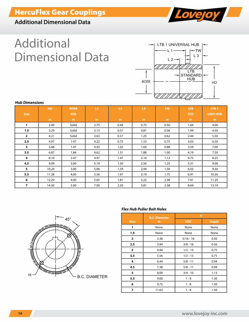
HercuFlex Gear CouplingsAdditional Dimensional Data
HDBORE
Flex Hub Puller Bolt Holes
SizeB.C. Diameter
in
H
UNC Depth
1 None None None
1.5 None None None
2 3.38 5/16 - 18 0.50
2.5 3.94 3/8 - 16 0.56
3 4.94 1/2 - 13 0.75
3.5 5.56 1/2 - 13 0.75
4 6.44 5/8 - 11 0.94
4.5 7.38 5/8 - 11 0.94
5 8.00 3/4 - 10 1.13
5.5 9.00 1 - 8 1.50
6 9.75 1 - 8 1.50
7 11.63 1 - 8 1.50
Additional Dimensional Data
Hub Dimensions
Size
HD BORE L1 L2 L3 TW LTB LTB 1
RSB STD UNIV HUB
in in in in in in in in
1 2.49 Solid 2.75 0.44 0.75 0.50 1.69 4.00
1.5 3.29 Solid 3.13 0.57 0.81 0.56 1.94 4.50
2 4.21 Solid 3.63 0.57 1.25 0.62 2.44 5.50
2.5 4.97 1.47 4.22 0.75 1.53 0.75 3.03 6.50
3 5.88 1.47 4.43 1.02 1.69 0.88 3.59 7.00
3.5 6.87 1.84 4.62 1.31 1.88 1.00 4.19 7.50
4 8.10 2.47 4.97 1.47 2.16 1.12 4.75 8.25
4.5 9.09 3.00 5.19 1.50 2.56 1.25 5.31 9.00
5 10.24 3.00 5.06 1.59 2.94 1.50 6.03 9.50
5.5 11.28 4.00 5.56 1.97 3.19 1.75 6.91 10.50
6 12.29 4.00 5.65 1.81 3.22 2.38 7.41 11.25
7 14.30 5.00 7.00 2.50 3.81 2.38 8.69 13.19
1-630-852-0500 15
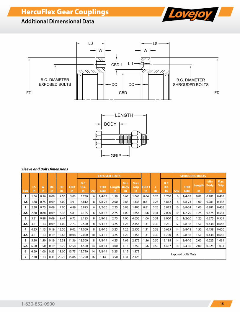
HercuFlex Gear CouplingsAdditional Dimensional Data
Sleeve and Bolt Dimensions
SizeLSin
Win
DCin
FDin
CBDin
EXPOSED BOLTS
CBD 1in
Lin
SHROUDED BOLTS
B.C.Dia.
in QtyTHD Size
Lengthin
MinBody
in
MaxGrip
in
B.C.Dia.
in QtyTHD Size
LengthMin
BodyMaxGrip
in in in
1 1.66 0.56 0.09 4.56 3.03 3.750 6 1/4-28 1.50 0.63 1.063 0.64 0.25 3.750 6 1/4-28 0.81 0.281 0.438
1.5 1.88 0.75 0.09 6.00 3.91 4.812 8 3/8-24 2.00 0.88 1.438 0.81 0.25 4.812 8 3/8-24 1.00 0.281 0.438
2 2.38 0.75 0.09 7.00 4.89 5.875 6 1/2-20 2.25 0.88 1.406 0.81 0.25 5.812 10 3/8-24 1.00 0.281 0.438
2.5 2.88 0.88 0.09 8.38 5.81 7.125 6 5/8-18 2.75 1.00 1.656 1.06 0.31 7.000 10 1/2-20 1.25 0.375 0.531
3 3.31 0.88 0.09 9.44 6.73 8.125 8 5/8-18 2.75 1.00 4.656 1.06 0.31 8.000 12 1/2-20 1.25 0.375 0.531
3.5 3.81 1.13 0.09 11.00 7.73 9.500 8 3/4-16 3.25 1.25 2.156 1.31 0.38 9.281 12 5/8-18 1.50 0.438 0.656
4 4.25 1.13 0.19 12.50 9.02 11.000 8 3/4-16 3.25 1.25 2.156 1.31 0.38 10.625 14 5/8-18 1.50 0.438 0.656
4.5 4.81 1.13 0.19 13.63 10.08 12.000 10 3/4-16 3.25 1.25 1.156 1.31 0.38 11.750 14 5/8-18 1.50 0.438 0.656
5 5.50 1.50 0.19 15.31 11.36 13.500 8 7/8-14 4.25 1.69 2.875 1.56 0.56 13.188 14 3/4-16 2.00 0.625 1.031
5.5 6.00 1.50 0.19 16.75 12.58 14.500 14 7/8-14 3.00 1.13 1.750 1.56 0.56 14.437 16 3/4-16 2.00 0.625 1.031
6 6.69 1.00 0.25 18.00 13.75 15.750 14 7/8-14 3.25 1.19 1.875Exposed Bolts Only
7 7.38 1.13 0.31 20.75 15.86 18.250 16 1-14 3.50 1.31 2.125
www.lovejoy-inc.com16
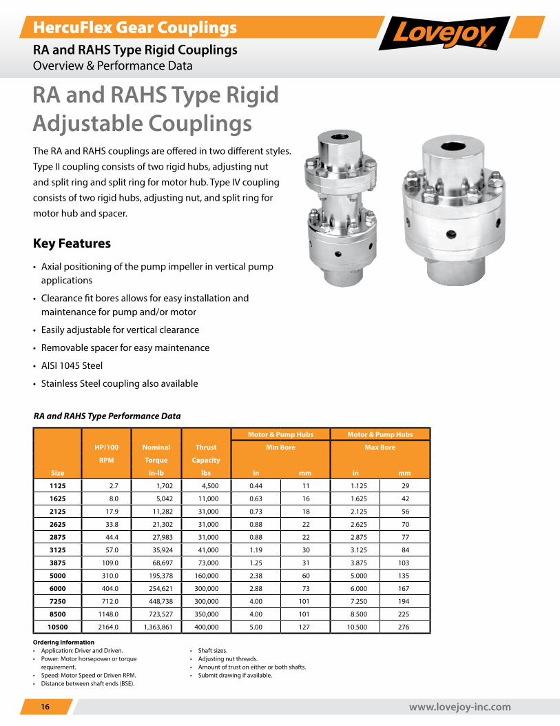
HercuFlex Gear CouplingsRA and RAHS Type Rigid CouplingsOverview & Performance Data
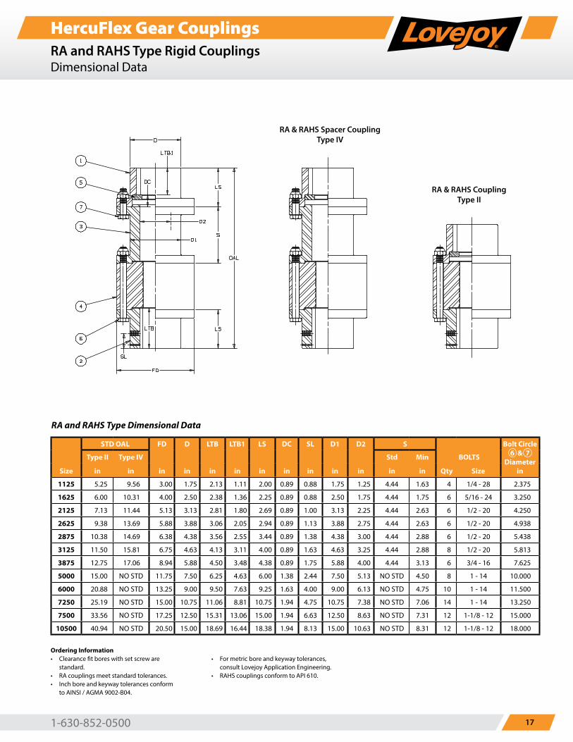
The RA and RAHS couplings are offered in two different styles.
Type II coupling consists of two rigid hubs, adjusting nut
and split ring and split ring for motor hub. Type IV coupling
consists of two rigid hubs, adjusting nut, and split ring for
motor hub and spacer.
Key Features
• Axial positioning of the pump impeller in vertical pump applications
• Clearance fit bores allows for easy installation and maintenance for pump and/or motor
• Easily adjustable for vertical clearance
• Removable spacer for easy maintenance
• AISI 1045 Steel
• Stainless Steel coupling also available
RA and RAHS Type Performance Data
Motor & Pump Hubs Motor & Pump Hubs
HP/100 Nominal Thrust Min Bore Max Bore
RPM Torque Capacity
Size in-lb lbs in mm in mm
1125 2.7 1,702 4,500 0.44 11 1.125 29
1625 8.0 5,042 11,000 0.63 16 1.625 42
2125 17.9 11,282 31,000 0.73 18 2.125 56
2625 33.8 21,302 31,000 0.88 22 2.625 70
2875 44.4 27,983 31,000 0.88 22 2.875 77
3125 57.0 35,924 41,000 1.19 30 3.125 84
3875 109.0 68,697 73,000 1.25 31 3.875 103
5000 310.0 195,378 160,000 2.38 60 5.000 135
6000 404.0 254,621 300,000 2.88 73 6.000 167
7250 712.0 448,738 300,000 4.00 101 7.250 194
8500 1148.0 723,527 350,000 4.00 101 8.500 225
10500 2164.0 1,363,861 400,000 5.00 127 10.500 276
Ordering Information• Application: Driver and Driven.• Power: Motor horsepower or torque
requirement.• Speed: Motor Speed or Driven RPM.• Distance between shaft ends (BSE).
• Shaft sizes.• Adjusting nut threads.• Amount of trust on either or both shafts.• Submit drawing if available.
RA and RAHS Type Rigid Adjustable Couplings
1-630-852-0500 17
HercuFlex Gear CouplingsRA and RAHS Type Rigid CouplingsDimensional Data
RA and RAHS Type Dimensional Data
STD OAL FD D LTB LTB1 LS DC SL D1 D2 S Bolt Circle6 & 7
Diameterin
Type II Type IV Std Min BOLTS
Size in in in in in in in in in in in in in Qty Size
1125 5.25 9.56 3.00 1.75 2.13 1.11 2.00 0.89 0.88 1.75 1.25 4.44 1.63 4 1/4 - 28 2.375
1625 6.00 10.31 4.00 2.50 2.38 1.36 2.25 0.89 0.88 2.50 1.75 4.44 1.75 6 5/16 - 24 3.250
2125 7.13 11.44 5.13 3.13 2.81 1.80 2.69 0.89 1.00 3.13 2.25 4.44 2.63 6 1/2 - 20 4.250
2625 9.38 13.69 5.88 3.88 3.06 2.05 2.94 0.89 1.13 3.88 2.75 4.44 2.63 6 1/2 - 20 4.938
2875 10.38 14.69 6.38 4.38 3.56 2.55 3.44 0.89 1.38 4.38 3.00 4.44 2.88 6 1/2 - 20 5.438
3125 11.50 15.81 6.75 4.63 4.13 3.11 4.00 0.89 1.63 4.63 3.25 4.44 2.88 8 1/2 - 20 5.813
3875 12.75 17.06 8.94 5.88 4.50 3.48 4.38 0.89 1.75 5.88 4.00 4.44 3.13 6 3/4 - 16 7.625
5000 15.00 NO STD 11.75 7.50 6.25 4.63 6.00 1.38 2.44 7.50 5.13 NO STD 4.50 8 1 - 14 10.000
6000 20.88 NO STD 13.25 9.00 9.50 7.63 9.25 1.63 4.00 9.00 6.13 NO STD 4.75 10 1 - 14 11.500
7250 25.19 NO STD 15.00 10.75 11.06 8.81 10.75 1.94 4.75 10.75 7.38 NO STD 7.06 14 1 - 14 13.250
7500 33.56 NO STD 17.25 12.50 15.31 13.06 15.00 1.94 6.63 12.50 8.63 NO STD 7.31 12 1-1/8 - 12 15.000
10500 40.94 NO STD 20.50 15.00 18.69 16.44 18.38 1.94 8.13 15.00 10.63 NO STD 8.31 12 1-1/8 - 12 18.000
Ordering Information• Clearance fit bores with set screw are
standard.• RA couplings meet standard tolerances.• Inch bore and keyway tolerances conform
to AINSI / AGMA 9002-B04.
• For metric bore and keyway tolerances, consult Lovejoy Application Engineering.
• RAHS couplings conform to API 610.
RA & RAHS Spacer CouplingType IV
RA & RAHS CouplingType II
www.lovejoy-inc.com18
HercuFlex Gear CouplingsContinuous Sleeve Gear CouplingsOverview
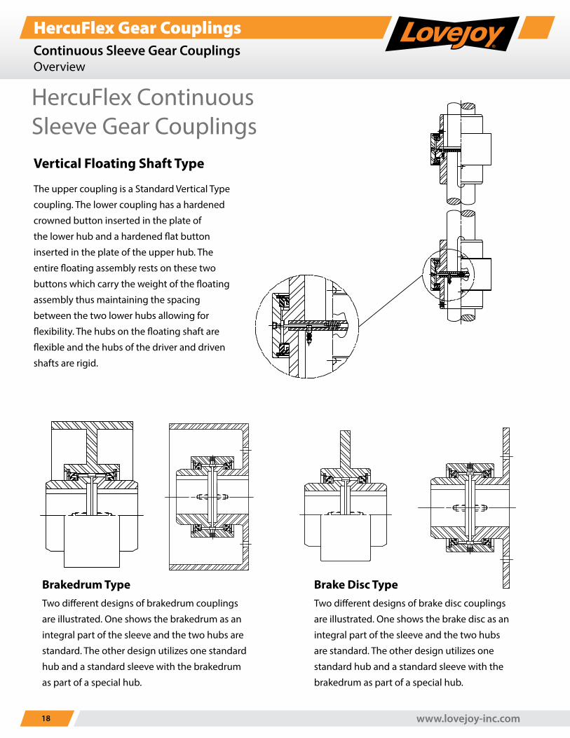
Vertical Floating Shaft Type
The upper coupling is a Standard Vertical Type
coupling. The lower coupling has a hardened
crowned button inserted in the plate of
the lower hub and a hardened flat button
inserted in the plate of the upper hub. The
entire floating assembly rests on these two
buttons which carry the weight of the floating
assembly thus maintaining the spacing
between the two lower hubs allowing for
flexibility. The hubs on the floating shaft are
flexible and the hubs of the driver and driven
shafts are rigid.
Brakedrum TypeTwo different designs of brakedrum couplings
are illustrated. One shows the brakedrum as an
integral part of the sleeve and the two hubs are
standard. The other design utilizes one standard
hub and a standard sleeve with the brakedrum
as part of a special hub.
Brake Disc TypeTwo different designs of brake disc couplings
are illustrated. One shows the brake disc as an
integral part of the sleeve and the two hubs
are standard. The other design utilizes one
standard hub and a standard sleeve with the
brakedrum as part of a special hub.
HercuFlex Continuous Sleeve Gear Couplings
1-630-852-0500 19
HercuFlex Gear CouplingsContinuous Sleeve Gear CouplingsOverview
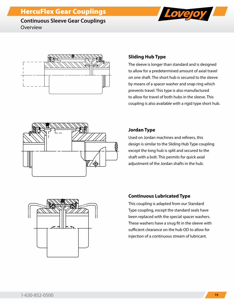
Sliding Hub TypeThe sleeve is longer than standard and is designed
to allow for a predetermined amount of axial travel
on one shaft. The short hub is secured to the sleeve
by means of a spacer washer and snap ring which
prevents travel. This type is also manufactured
to allow for travel of both hubs in the sleeve. This
coupling is also available with a rigid type short hub.
Jordan TypeUsed on Jordan machines and refiners, this
design is similar to the Sliding Hub Type coupling
except the long hub is split and secured to the
shaft with a bolt. This permits for quick axial
adjustment of the Jordan shafts in the hub.
Continuous Lubricated TypeThis coupling is adapted from our Standard
Type coupling, except the standard seals have
been replaced with the special spacer washers.
These washers have a snug fit in the sleeve with
sufficient clearance on the hub OD to allow for
injection of a continuous stream of lubricant.
www.lovejoy-inc.com20
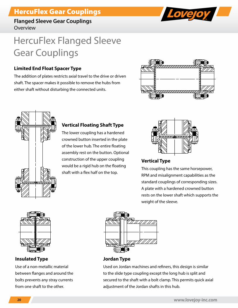
HercuFlex Gear CouplingsFlanged Sleeve Gear CouplingsOverview
Vertical TypeThis coupling has the same horsepower,
RPM and misalignment capabilities as the
standard couplings of corresponding sizes.
A plate with a hardened crowned button
rests on the lower shaft which supports the
weight of the sleeve.
Jordan TypeUsed on Jordan machines and refiners, this design is similar
to the slide type coupling except the long hub is split and
secured to the shaft with a bolt clamp. This permits quick axial
adjustment of the Jordan shafts in this hub.
Insulated TypeUse of a non-metallic material
between flanges and around the
bolts prevents any stray currents
from one shaft to the other.
Vertical Floating Shaft TypeThe lower coupling has a hardened
crowned button inserted in the plate
of the lower hub. The entire floating
assembly rest on the button. Optional
construction of the upper coupling
would be a rigid hub on the floating
shaft with a flex half on the top.
HercuFlex Flanged Sleeve Gear CouplingsLimited End Float Spacer TypeThe addition of plates restricts axial travel to the drive or driven
shaft. The spacer makes it possible to remove the hubs from
either shaft without disturbing the connected units.
1-630-852-0500 21
HercuFlex Gear CouplingsFlanged Sleeve Gear CouplingsOverview
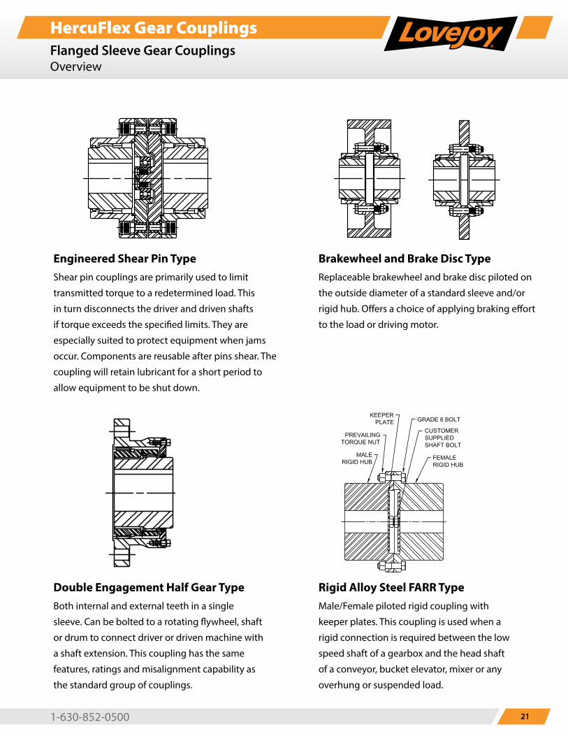
Engineered Shear Pin TypeShear pin couplings are primarily used to limit
transmitted torque to a redetermined load. This
in turn disconnects the driver and driven shafts
if torque exceeds the specified limits. They are
especially suited to protect equipment when jams
occur. Components are reusable after pins shear. The
coupling will retain lubricant for a short period to
allow equipment to be shut down.
Double Engagement Half Gear TypeBoth internal and external teeth in a single
sleeve. Can be bolted to a rotating flywheel, shaft
or drum to connect driver or driven machine with
a shaft extension. This coupling has the same
features, ratings and misalignment capability as
the standard group of couplings.
Brakewheel and Brake Disc TypeReplaceable brakewheel and brake disc piloted on
the outside diameter of a standard sleeve and/or
rigid hub. Offers a choice of applying braking effort
to the load or driving motor.
Rigid Alloy Steel FARR TypeMale/Female piloted rigid coupling with
keeper plates. This coupling is used when a
rigid connection is required between the low
speed shaft of a gearbox and the head shaft
of a conveyor, bucket elevator, mixer or any
overhung or suspended load.
www.lovejoy-inc.com22
HercuFlex Gear CouplingsCoupling GreaseOverview
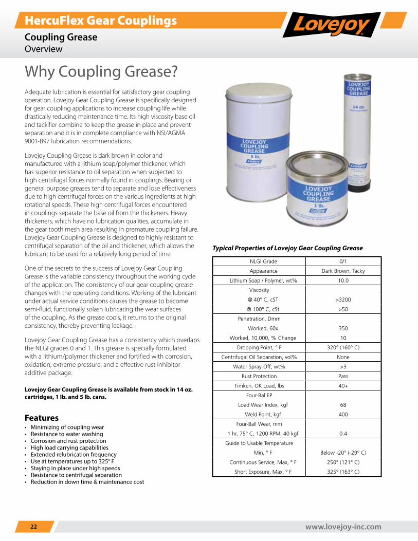
Why Coupling Grease?Adequate lubrication is essential for satisfactory gear coupling operation. Lovejoy Gear Coupling Grease is specifically designed for gear coupling applications to increase coupling life while drastically reducing maintenance time. Its high viscosity base oil and tackifier combine to keep the grease in place and prevent separation and it is in complete compliance with NSI/AGMA 9001-B97 lubrication recommendations.
Lovejoy Coupling Grease is dark brown in color and manufactured with a lithium soap/polymer thickener, which has superior resistance to oil separation when subjected to high centrifugal forces normally found in couplings. Bearing or general purpose greases tend to separate and lose effectiveness due to high centrifugal forces on the various ingredients at high rotational speeds. These high centrifugal forces encountered in couplings separate the base oil from the thickeners. Heavy thickeners, which have no lubrication qualities, accumulate in the gear tooth mesh area resulting in premature coupling failure. Lovejoy Gear Coupling Grease is designed to highly resistant to centrifugal separation of the oil and thickener, which allows the lubricant to be used for a relatively long period of time.
One of the secrets to the success of Lovejoy Gear Coupling Grease is the variable consistency throughout the working cycle of the application. The consistency of our gear coupling grease changes with the operating conditions. Working of the lubricant under actual service conditions causes the grease to become semi-fluid, functionally solash lubricating the wear surfaces of the coupling. As the grease cools, it returns to the original consistency, thereby preventing leakage.
Lovejoy Gear Coupling Grease has a consistency which overlaps the NLGI grades 0 and 1. This grease is specially formulated with a lithium/polymer thickener and fortified with corrosion, oxidation, extreme pressure, and a effective rust inhibitor additive package.
Lovejoy Gear Coupling Grease is available from stock in 14 oz. cartridges, 1 lb. and 5 lb. cans.
Typical Properties of Lovejoy Gear Coupling Grease
NLGI Grade 0/1
Appearance Dark Brown, Tacky
Lithium Soap / Polymer, wt% 10.0
Viscosity
@ 40° C, cST >3200
@ 100° C, cSt >50
Penetration. Dmm
Worked, 60x 350
Worked, 10,000, % Change 10
Dropping Point, ° F 320° (160° C)
Centrifugal Oil Separation, vol% None
Water Spray-Off, wt% >3
Rust Protection Pass
Timken, OK Load, lbs 40+
Four-Bal EP
Load Wear Index, kgf 68
Weld Point, kgf 400
Four-Ball Wear, mm
1 hr, 75° C, 1200 RPM, 40 kgf 0.4
Guide to Usable Temperature
Min, ° F Below -20° (-29° C)
Continuous Service, Max, ° F 250° (121° C)
Short Exposure, Max, ° F 325° (163° C)
Features• Minimizing of coupling wear• Resistance to water washing• Corrosion and rust protection• High load carrying capabilities• Extended relubrication frequency• Use at temperatures up to 325° F• Staying in place under high speeds• Resistance to centrifugal separation• Reduction in down time & maintenance cost
1-630-852-0500 23
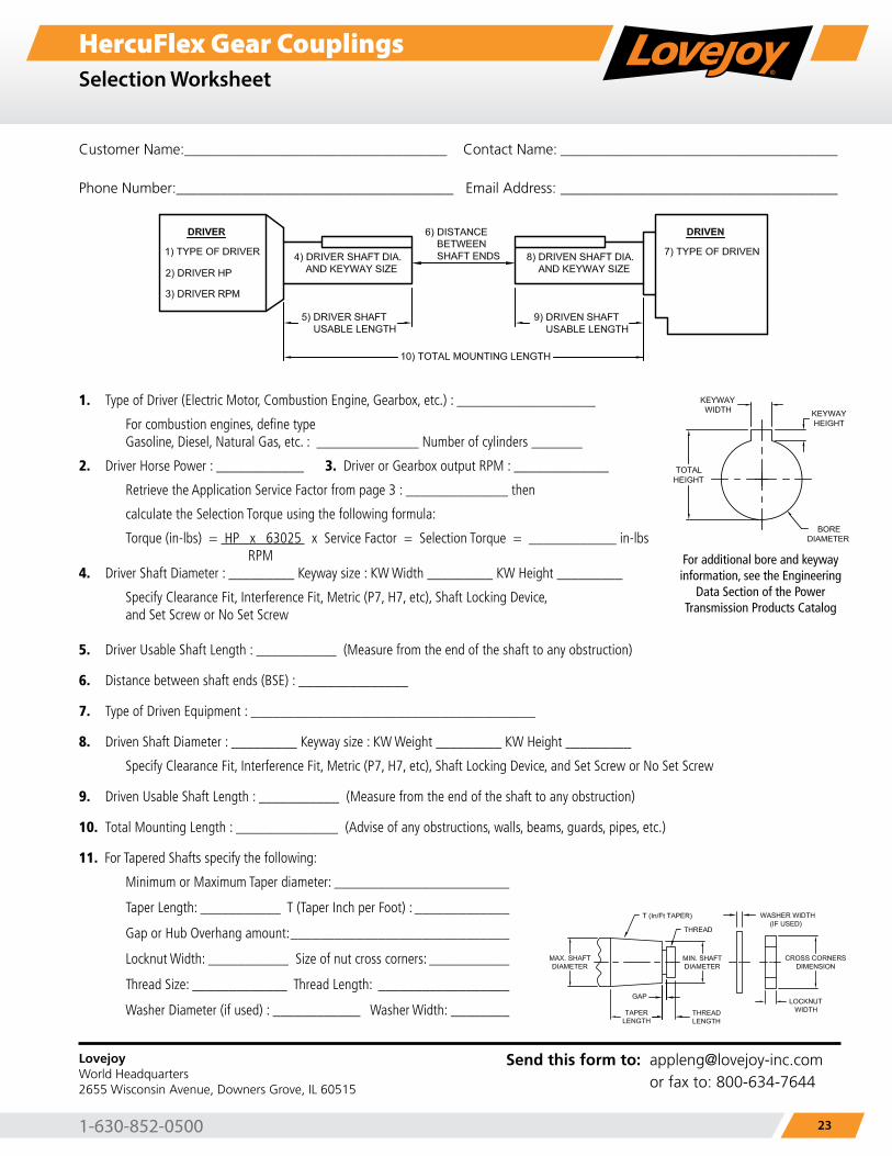
HercuFlex Gear CouplingsSelection Worksheet
Customer Name:____________________________________ Contact Name: ______________________________________
Phone Number:______________________________________ Email Address: ______________________________________
1. Type of Driver (Electric Motor, Combustion Engine, Gearbox, etc.) : ___________________
For combustion engines, define type Gasoline, Diesel, Natural Gas, etc. : ______________ Number of cylinders _______
2. Driver Horse Power : ____________ 3. Driver or Gearbox output RPM : _____________
Retrieve the Application Service Factor from page 3 : ______________ then
calculate the Selection Torque using the following formula:
Torque (in-lbs) = HP x 63025 x Service Factor = Selection Torque = ____________ in-lbs RPM4. Driver Shaft Diameter : _________ Keyway size : KW Width _________ KW Height _________
Specify Clearance Fit, Interference Fit, Metric (P7, H7, etc), Shaft Locking Device, and Set Screw or No Set Screw
5. Driver Usable Shaft Length : ___________ (Measure from the end of the shaft to any obstruction)
6. Distance between shaft ends (BSE) : _______________
7. Type of Driven Equipment : _______________________________________
8. Driven Shaft Diameter : _________ Keyway size : KW Weight _________ KW Height _________
Specify Clearance Fit, Interference Fit, Metric (P7, H7, etc), Shaft Locking Device, and Set Screw or No Set Screw
9. Driven Usable Shaft Length : ___________ (Measure from the end of the shaft to any obstruction)
10. Total Mounting Length : ______________ (Advise of any obstructions, walls, beams, guards, pipes, etc.)
11. For Tapered Shafts specify the following:
Minimum or Maximum Taper diameter: ________________________
Taper Length: ___________ T (Taper Inch per Foot) : _____________
Gap or Hub Overhang amount: ______________________________
Locknut Width: ___________ Size of nut cross corners: ___________
Thread Size: _____________ Thread Length: __________________
Washer Diameter (if used) : ____________ Washer Width: ________
For additional bore and keyway information, see the Engineering
Data Section of the Power Transmission Products Catalog
LovejoyWorld Headquarters2655 Wisconsin Avenue, Downers Grove, IL 60515
Send this form to: [email protected] or fax to: 800-634-7644
www.lovejoy-inc.com24
HercuFlex Gear CouplingsProduct Warranty
Product Warranty
Lovejoy, Inc. warrants all products it manufactures to be free from defects in material and workmanship at
the time of delivery to the purchaser. Defective products may be returned to Lovejoy after inspection by the
purchaser and upon receipt from Lovejoy of shipping instructions specific to the defective products authorized
by Lovejoy to be returned. Products returned in accordance with the foregoing procedure will be replaced or
repaired, at the option of Lovejoy, without charge and returned to the purchaser F.O.B. Downers Grove, Illinois or
South Haven, Michigan, depending upon origin of manufacture. In all cases, transportation costs and charges for
returned products shall be paid by the purchaser and Lovejoy hereby disclaims all responsibility for any and all
such transportation costs and charges.
This warranty is subject to the following LIMITATIONS:
The purchaser’s exclusive remedy under this warranty is limited to the repair or replacement of defective
products supplied by Lovejoy, as set forth above. LOVEJOY IS NOT RESPONSIBLE FOR ANY SPECIAL, INCIDENTAL
OR CONSEQUENTIAL DAMAGES RESULTING FROM THE BREACH OF THIS OR ANY OTHER EXPRESS OR IMPLIED
WARRANTY WITH RESPECT TO THE PRODUCTS, WHETHER ARISING IN TORT OR BY CONTRACT. LOVEJOY FURTHER
DISCLAIMS ALL LIABILITY FROM PERSONAL INJURY RELATING TO ITS PRODUCTS TO THE EXTENT PERMITTED BY
LAW. BY ACCEPTANCE OF ANY OF LOVEJOY’S PRODUCTS, THE PURCHASER ASSUMES ALL LIABILITY FOR THE
CONSEQUENCES ARISING FROM THEIR USE OR MISUSE.
This express warranty is the only warranty applicable to this transaction. IT EXCLUDES ALL OTHER EXPRESS ORAL
OR WRITTEN WARRANTIES AND ALL WARRANTIES IMPLIED BY LAW WITH RESPECT TO THE PRODUCTS, INCLUDING ANY
WARRANTIES OF MERCHANTABILITY OR FITNESS FOR A PARTICULAR PURPOSE.
Every claim under this warranty shall be deemed waived by the purchaser unless made in writing within one (1)
year of the receipt of the products to which such claim relates. This warranty is void in the event that repairs are
made by anyone other than Lovejoy without prior authorization from Lovejoy. No person, firm or corporation is
authorized to assume for Lovejoy any other liability in connection with the sale of its products. No person, firm
or corporation is authorized to modify or waive the terms of this Warranty unless done in writing and signed by a
duly authorized agent of Lovejoy.
Note: Specifications are subject to change without notice, and without liability therefor.
1-630-852-0500 25
HercuFlex Gear CouplingsNotes
Notes
www.lovejoy-inc.com26
HercuFlex Gear CouplingsNotes
Notes


The leader in power transmission products.
Your Authorized Lovejoy Distributor is:
Lovejoy®, R+L Hydraulics GmbH, HercuFlex and RunRight are registered trademarks of Lovejoy.
Lovejoy
2655 Wisconsin AvenueDowners Grove, IL 60515 USAPhone: 630-852-0500Fax: [email protected]
www.lovejoy-inc.com
R+L Hydraulics GmbH
Friedrichstrasse 6 D-58791 Werdohl Germany Phone +49 (0) 23 92 / 5 09-0 Fax +49 (0) 23 92 / 5 09-509 [email protected]
www.rl-hydraulics.com
Timken Canada
171 Superior BoulevardMississauga, OntarioCanada L5T 2L6Phone: 905-670-9421Fax: [email protected]
www.lovejoy-inc.com
Curtis Universal Joint Co., Inc.
4 Birnie AvenueSpringfield, MA 01107413-748-6463413-748-6461 [email protected]
www.curtisuniversal.com
ISO 9001 Certified
Rev E UPC 697904483052.5M 10-18 Order No. 11170 | Timken® is a registered trademark of The Timken Company. | © 2018 The Timken Company | Printed in U.S.A. All other trademarks are the property of their respective owners.