Hemodynamic Response Detection Using Integrated EEG-fNIRS ...
21
ech T Press Science Computers, Materials & Continua DOI:10.32604/cmc.2022.018318 Article Hemodynamic Response Detection Using Integrated EEG-fNIRS-VPA for BCI Arshia Arif 1 , M. Jawad Khan 1,2, * , Kashif Javed 1 , Hasan Sajid 1,2 , Saddaf Rubab 1 , Noman Naseer 3 and Talha Irfan Khan 4 1 National University of Sciences and Technology (NUST), Islamabad, Pakistan 2 Intelligent Robotics Lab, National Center of Artificial Intelligence, National University of Sciences and Technology (NUST), Islamabad, Pakistan 3 Department of Mechatronics Engineering, Air University, Islamabad, Pakistan 4 Institute of Space Technology, Islamabad, Pakistan * Corresponding Author: M. Jawad Khan. Email: [email protected] Received: 04 March 2021; Accepted: 21 April 2021 Abstract: For BCI systems, it is important to have an accurate and less complex architecture to control a device with enhanced accuracy. In this paper, a novel methodology for more accurate detection of the hemodynamic response has been developed using a multimodal brain-computer interface (BCI). An inte- grated classifier has been developed for achieving better classification accuracy using two modalities. An integrated EEG-fNIRS-based vector-phase analysis (VPA) has been conducted. An open-source dataset collected at the Technis- che Universität Berlin, including simultaneous electroencephalography (EEG) and functional near-infrared spectroscopy (fNIRS) signals of 26 healthy par- ticipants during n-back tests, has been used for this research. Instrumental and physiological noise removal has been done using preprocessing techniques followed by individually detecting activity in both modalities. With resting state threshold circle, VPA has been used to detect a hemodynamic response in fNIRS signals, whereas phase plots for EEG signals have been constructed using Hilbert Transform to detect the activity in each trial. Multiple threshold circles are drawn in the vector plane, where each circle is drawn after task com- pletion in each trial of EEG signal. Finally, both processes are integrated into one vector-phase plot to get combined detection of hemodynamic response for activity. Results of this study illustrate that the combined EEG-fNIRS VPA yields considerably higher average classification accuracy, that is 91.35%, as compared to other classifiers such as support vector machine (SVM), con- volutional neural networks (CNN), deep neural networks (DNN) and VPA (with dual-threshold circles) with classification accuracies 82%, 89%, 87% and 86% respectively. Outcomes of this research demonstrate that improved classification performance can be feasibly achieved using multimodal VPA for EEG-fNIRS hybrid data. Keywords: EEG-fNIRS hybrid BCI; vector-phase analysis; hemodynamic response detection This work is licensed under a Creative Commons Attribution 4.0 International License, which permits unrestricted use, distribution, and reproduction in any medium, provided the original work is properly cited.
Transcript of Hemodynamic Response Detection Using Integrated EEG-fNIRS ...

echT PressScienceComputers, Materials & ContinuaDOI:10.32604/cmc.2022.018318
Article
Hemodynamic Response Detection Using Integrated EEG-fNIRS-VPA for BCI
Arshia Arif1, M. Jawad Khan1,2,*, Kashif Javed1, Hasan Sajid1,2, Saddaf Rubab1, Noman Naseer3 andTalha Irfan Khan4
1National University of Sciences and Technology (NUST), Islamabad, Pakistan2Intelligent Robotics Lab, National Center of Artificial Intelligence, National University of Sciences and Technology
(NUST), Islamabad, Pakistan3Department of Mechatronics Engineering, Air University, Islamabad, Pakistan
4Institute of Space Technology, Islamabad, Pakistan*Corresponding Author: M. Jawad Khan. Email: [email protected]
Received: 04 March 2021; Accepted: 21 April 2021
Abstract:For BCI systems, it is important to have an accurate and less complexarchitecture to control a device with enhanced accuracy. In this paper, a novelmethodology for more accurate detection of the hemodynamic response hasbeen developed using a multimodal brain-computer interface (BCI). An inte-grated classifier has been developed for achieving better classification accuracyusing two modalities. An integrated EEG-fNIRS-based vector-phase analysis(VPA) has been conducted. An open-source dataset collected at the Technis-che Universität Berlin, including simultaneous electroencephalography (EEG)and functional near-infrared spectroscopy (fNIRS) signals of 26 healthy par-ticipants during n-back tests, has been used for this research. Instrumentaland physiological noise removal has been done using preprocessing techniquesfollowed by individually detecting activity in both modalities. With restingstate threshold circle, VPA has been used to detect a hemodynamic responsein fNIRS signals, whereas phase plots for EEG signals have been constructedusing Hilbert Transform to detect the activity in each trial. Multiple thresholdcircles are drawn in the vector plane, where each circle is drawn after task com-pletion in each trial of EEG signal. Finally, both processes are integrated intoone vector-phase plot to get combined detection of hemodynamic response foractivity. Results of this study illustrate that the combined EEG-fNIRS VPAyields considerably higher average classification accuracy, that is 91.35%, ascompared to other classifiers such as support vector machine (SVM), con-volutional neural networks (CNN), deep neural networks (DNN) and VPA(with dual-threshold circles) with classification accuracies 82%, 89%, 87%and 86% respectively. Outcomes of this research demonstrate that improvedclassification performance can be feasibly achieved using multimodal VPA forEEG-fNIRS hybrid data.
Keywords: EEG-fNIRS hybrid BCI; vector-phase analysis; hemodynamicresponse detection
This work is licensed under a Creative Commons Attribution 4.0 International License,which permits unrestricted use, distribution, and reproduction in any medium, providedthe original work is properly cited.

536 CMC, 2022, vol.70, no.1
1 Introduction
A brain-computer interface (BCI) is a pathway for communication between brain thoughtsand computer to achieve hardware control, without any dependence on channels like nerves andmuscles. [1,2]. The main purpose of a BCI is to equip physically impaired people, especially withmotor disabilities, with the facility to communicate with the help of their brain signals [3,4]. ABCI is used to detect and interpret brain signals to control the devices [5]. A BCI helps usersdevelop an interface between their brain and peripheral devices without any kind of physicalmovement [6–9]. Different neuroimaging modalities measurbrain activity via different aspects ofbrain signals [10]. Various assistive rehabilitative devices have been controlled using different typesof BCI systems [11], such as electroencephalography (EEG) [12,13] and functional near-infraredspectroscopy (fNIRS) [14,15] etc.
EEG and fNIRS are two of the significant non-invasive modalities. Being portable, costeffective and less noisy, counts as the major benefits of these modalities [6,16]. EEG is a signalformed by the field potential generated due to the collective and synchronous action of neurons.As a non-invasive BCI, voltage fluctuations can be recorded with the help of electrodes placed onthe scalp [17]. EEG is one of the modalities which are mostly used nowadays for research [18,19].EEG has its own strengths and drawbacks. For example, EEG possesses good temporal resolution(∼0.05 s), whereas its spatial resolution is poor (∼10 mm) [4]. Localization of activity in the brainis inaccurate due to poor spatial resolution of EEG [20]. EEG is also more sensitive to motionartifacts compared to fNIRS [21,22].
fNIRS is one of the emerging BCIs which records brain activity as blood oxygen levelchanges. It uses near-infrared-range light of wavelength 650∼1000 nm to estimate the variations inthe concentration of oxygenated hemoglobin (�HbO) and deoxygenated hemoglobin (�HbR) [23].fNIRS also has its strengths and drawbacks. For example, fNIRS’s temporal resolution (∼1 s) isjust moderate, whereas it offers reasonably better spatial resolution(∼5 mm) than EEG [4].
A hybrid BCI system is usually comprised of two BCIs. It can also be composed of at leastone BCI system and another system (ECG and EMG etc.) [24,25]. It can also have one brainsignal and a non-brain signal as its inputs. A hybrid BCI is expected to achieve better performanceand classification accuracy than other conventional systems [26]. EEG and fNIRS measure thecomplementary characteristics of brain signals, i.e., electrophysiological and hemodynamic aspects,so a hybrid BCI integrates more information producing better results than using individualmodalities [27–30].
Accuracy is one of the major concerns of most researchers to evaluate brain-computermachines. There is a need to develop a hybrid EEG-fNIRS architecture that can enhance theaccuracy for better performance and control of devices. Thus, to further improve the accuracy, inthis study, we have devised a novel methodology using an open-source meta-dataset comprisingof simultaneous EEG and fNIRS data of 26 healthy subjects, integrated at Technische UniversitätBerlin is available online (http://doc.ml.tu-berlin.de/simultaneous_EEG_NIRS/). The n-back testhas been carried out on all these participants (more explanation in next section) [31].
The rest of this study is organized as follows. Section 2 investigates the literature work andpresents a review on the techniques/methods for early response detection using EEG. Section 3provides details of the dataset and discusses the preprocessing process. Section 4 describes thedesign details of the proposed method. Section 5 presents the experimental results. Section 6outlines the conclusion and discusses the limitations of the proposed method.
CMC, 2022, vol.70, no.1 537
2 Literature Review and Related Work
Vector-phase analysis (VPA) displays the trajectory formed as a result of oxy-hemoglobin(�HbO) and deoxy-hemoglobin (�HbR) concentration changes [32]. Magnitude and angle, cal-culated using �HbO and �HbR, are used to construct a two-dimensional vector plane [33].This plane is divided into eight phases for the classification of hemodynamic response [34]. Athreshold circle is plotted on the vector plane to detect brain activity [35]. This method has alreadybeen used for neuronal activation detection [32], initial dip detection in hemodynamic response[32,36–38], reduction of delay in initial dip detection [35], oxygen level detection in prefrontalcortex [39] and determining the brain region of interest for BCI [40]. VPA, with dual-thresholdcircles, has been used for early hemodynamic response detection using EEG. The second thresholdcircle has been drawn using �HbO and �HbR magnitudes during the time span when a noticeableEEG activity has been sensed. During this time window, highest EEG power has been used as acriterion to select the corresponding �HbO and �HbR magnitudes, which are then further usedto determine the magnitude of the second circle. The accuracy reported with this technique is86% [41].
Different researches have been carried out on the dataset selected for this research, and effortshave been made to improve the classification accuracy [31]. Studies have been done on this datasetwith the implementation of machine learning techniques and deep learning algorithms. Event-related potential (ERP) analysis has been conducted on this dataset in 2018, for which the averageaccuracy turned out to be 76.5% ± 8%) [31]. SVM and CNN were applied for 7 out of 26 subjectsin 2020 to classify mental workload. The average classification accuracy using SVM is 70.64%,and that for CNN is 83.42% [42]. Then in a comprehensive study of 2020, SVM and CNN wereapplied to hybrid EEG-fNIRS dataset of the n-back task for 26 subjects, resulting in averageclassification accuracy of 82% and 89%, respectively [43]. In another research of 2020, DNN wasemployed for 26 subjects using a hybrid dataset and for the n-back task, an average accuracy of87% was achieved [5]. There is still room for improvement in the classification accuracy for whichwe have devised a novel methodology.
In this paper, we propose a novel modified multimodal VPA methodology to detect activityin hemodynamic response. We have used state-of-the-art hybrid BCI (EEG-fNIRS) data for the n-back test for the presented methodology. Complete data has been preprocessed using conventionalways to make it noise-free. Initially, both the modalities have been dealt with individually. Hilberttransform has been applied to EEG signals to get the required magnitude and phase values toconstruct polar plots of all the trials. Then, activity is detected using these polar plots.
Similarly, VPA has been applied to fNIRS signals to construct vector-based phase plot forhemodynamic response detection with a resting state threshold circle as a detection criterion.Finally, an integrated multimodal VPA has been designed with multiple threshold circles, basedon the activity completion of each EEG signal trial, to achieve better detection of hemodynamicresponse. This proposed design yield 91.35% average classification accuracy, which is significantlyhigher than other techniques mentioned previously.
3 Dataset and Preprocessing
3.1 Subjects/ParticipantsAn open-source dataset has been used for this research (http://doc.ml.tu-berlin.de/simultaneous
_EEG_NIRS/) [31]. Data has been collected at Technische Universität Berlin. Twenty-six subjects,with an average age of almost 26.1 ± 3.5 years, who participated in this data collection were

538 CMC, 2022, vol.70, no.1
healthy right-handed people. Nine of them were males, and 17 were females [31]. None of thempossessed any mental, neuronal, or brain-related disorder. Written consent was taken from all thesubjects after informing them about the complete experimental paradigm [31].
3.2 Experimental ParadigmEach participant was provided with a comfortable armchair to sit in front of a 24’ LCD
screen. Distance between the person’s eyes and the screen was 1.2 m. The right armrest hadnumeric keypad buttons (number 7 and 8) fixed to it. All participants were directed to look at thescreen and try to abstain from moving their body. This experiment comprised of three types oftasks (n-back tasks, discrimination/selection response tasks and word generation tasks) with threesessions each. For this study, we have used the n-back task dataset [31].
3.3 Dataset: N-BackThis dataset of the n-back test was comprised of three sessions for every subject as shown
in Fig. 1, where every session had nine series of three types, i.e., 0-, 2- and 3-back tasks, in acounterbalanced order (i.e., 0 → 2 → 3 → 2 → 3 → 0 → 3 → 0 → 2). Every series consistedof 2 s instruction time, displaying the type of series (0-, 2- and 3-back), followed by a 40 s taskperiod, 1 s time for “STOP” word and a 20 s rest period. Hence, each series was composed oftotal of 63 s [31].
Figure 1: Experimental paradigm for n-back task
A short beep of 250 ms was used to signify the person about the beginning and end ofevery task period. A fixation cross was shown on the screen for the rest period. Every task periodconsisted of twenty trials, each of 2 s. In every trial, a random one-digit number was displayedon the screen for 0.5 s, followed by a fixation cross for 1.5 s. For the 0-back test, participants

CMC, 2022, vol.70, no.1 539
pressed either the number 7 button for a ‘target’ digit or number 8 button for a ‘non-target’digit. In the case of 2- and 3-back tasks, participants were instructed to press the ‘target’ button,number 7, if presently shown digit matched the 2 or 3 preceding numbers respectively, otherwisethe ‘non-target’ button 8. For each type of n-back task, a total of 180 trials were carried out(3 session × 3 series × 20 trials) [31].
Total three sessions were conducted with 9 series each, and every series was comprised ofinitial 2 s of instruction about the type of task (0-, 2- and 3-back), the 40 s of the task, 1 s of“STOP” word shown and 20 s of rest. The task period had 20 trials in it, and each trial of atotal of 2 s consisted of 0.5 s of digit display and 1.5 s of fixation cross display [31].
3.4 Data Acquisition and Channel ConfigurationfNIRS and EEG signals were recorded in parallel. EEG data were acquired at the sampling
frequency of 200 Hz using a multichannel BrainAmp EEG amplifier (Brain Products GmbH,Gilching, Germany). According to the international 10–5 system, thirty electrodes were attachedto a flexible fabric cap (EASYCAP GmbH, Herrsching am Ammersee, Germany) as shown inFig. 2 (Fp1, Fp2, AFF5h, AFF6h, AFz, F1, F2, FC1, FC2, FC5, FC6, Cz, C3, C4, T7, T8,CP1, CP2, CP5, CP6, Pz, P3, P4, P7, P8, POz, O1, O2, TP9 (reference) and TP10 (ground)).Electrooculogram (EOG) was also measured using an EEG amplifier. EOG was also recordedat the same sampling frequency as EEG, with the help of two vertical and two horizontalelectrodes [31]. Out of all these channels, seven frontal channels (Fp1, Fp2, AFF5h, AFF6h, AFz,F1, F2) were used for this study. Frontal channels have been chosen because n-back task is acognitive task, and its activity signals are expected to appear in the frontal cortex. The frontalregion has been indicated in Fig. 2.
Figure 2: Channel configuration of EEG and fNIRS. Blue circles denote the EEG channels,whereas red circles denote the fNIRS channels [31]. The frontal region (4 cm × 12 cm) has beenhighlighted in the red rectangle in this figure
fNIRS data was recorded at the sampling frequency of 10Hz with a NIRScout (NIRxMedizintechnik GmbH, Berlin, Germany). Sixteen sources and sixteen detectors were attached atfrontal (sixteen channels around AFz, AF3, AF4, AF7 and AF8), parietal (four channels eacharound P3 and P4), motor (four channels each around C3 and C4), and occipital (four channelsaround POz) areas. An adjoining source-detector pair sets up an fNIRS channel. A configuration

540 CMC, 2022, vol.70, no.1
of a total of 36 channels was formed. The fNIRS channels were configured according to theinternational 10–5 system around AFpz, AFp3, AFp4, AFp7, AFp8, AF1, AF2, AF7, AF8,AF5h, AF6h, AFFz, AFF3h, AFF4h, AFF5, AFF6, FCC3, FCC4, C3h, C4h, C5h, C6h, CCP3,CCP4, CPP3, CPP4, P3h, P4h, P5h, P6h, PPOz, PPO3, PPO4, PO1, PO2, and POOz as shownin Fig. 2. For this configuration, the distance between source and detector was set to 30 mmfor every channel. Fig. 2 displays the frontal channels’ configuration for EEG and fNIRS [31].Blue circles are indicating the EEG channel locations, whereas red circles are denoting the fNIRSchannels.
Twelve frontal channels (i.e., AF1, AF2, AFF5, AFF6, AFFz, AFpz, AFp3, AFp4, AF5h,AF6h, AFF3h, AFF4h) were used for this study based on the activity signal appearance in theirhemodynamic response, as can be seen clearly from their VPA diagrams for all types of tasks (0-,2- and 3-back) in Fig. 3.
Figure 3: VPA Plots for fNIRS frontal channels for all 3 tasks (0-, 2- and 3-back tasks). Theselected channel are the ones encaptured by dotted line boxes. Channels 1 (AF7), 2 (AFF5)and 3 (AFp7) are shown in the figure. Remaining channels are shown in the figure provided insupplementary material
3.5 Data PreprocessingBefore using the data for any technique, we have preprocessed the signals to get the best
possible results. For EEG data, since the fundamental frequencies for this data were lying in thealpha (α) (8–13 Hz) and theta (θ) (4–8 Hz) bands, so, to remove the noise and to remain withinthe interested frequency bands, a bandpass filter (5th order, Butterworth filter) of 0.1–15 Hz has

CMC, 2022, vol.70, no.1 541
been applied to these signals to achieve the optimum outcomes. fNIRS data was already in theform of �HbO and �HbR concentration changes, so there was no need to apply Beer–Lambertlaw. A low pass filter with cut off frequency 0.2 Hz (6th order, Butterworth filter) followed by ahigh pass filter with cutoff frequency 0.01 Hz has been applied to the data to achieve signal withinthe frequency range of 0.01–0.2 Hz as the fundamental frequencies for this data were present inthis band [31]. The intention behind applying these filters to fNIRS data was also to remove theinstrumental and physiological noise present in the data.
4 Proposed Integrated Vector Phase Analysis
4.1 Hilbert TransformIn this research, Hilbert transform (HT) has been used to calculate the imaginary component
of EEG signals along with their phases and magnitudes. Polar plot construction for each trial ofeach series of all EEG signals is then achieved to detect activity.
For an EEG signal x(t), the imaginary component y(t) can be calculated using HT [44] asfollows:
H[x (t)]= y (t)= 1π
∫ ∞
−∞x(τ )
t− τdτ (1)
Then the analytical signal corresponding to x(t) can be written as:
z (t)= x (t)+ iy (t)= a(t)eiθ(t) (2)
where x(t) and y(t) are complex conjugates of each other and the magnitude |z(t)| and phase∠z(t) are defined as
|z (t) | = (x2+ y2)12 (3)
and
∠z(t)= tan−1 y(t)x(t)
(4)
Outcomes of HT are used to construct the polar plots of EEG signal trials to indicate activity.Mean values are calculated, for both (x and y) coordinates using the complete trajectory in thephase plot, as meanx and meany respectively. In this research, we have set the criterion that ifmeanx is greater than 0, it is considered the occurrence of activity (more explanation in the nextsection with results).
4.2 Vector Phase AnalysisThe vector-phase analysis is a technique that can be used to detect the hemodynamic response
by using just the two components, �HbO and �HbR, of fNIRS signals [14] In this method, thereis a vector plane which is based on two orthogonal axes with �HbO values at x-axis and �HbRvalues at the y-axis. This plane is divided into eight phases [37,39,45,46] by getting two more axesin the plane. When the �HbO and �HbR plane is rotated counterclockwise by 45◦, the other twoaxes, i.e., �HBT (total hemoglobin) and �COE (cerebral oxygen exchange), come into existence.�HBT and �COE can be defined as:
ΔHBT = ΔHbO+ΔHbR√2
(5)
542 CMC, 2022, vol.70, no.1
ΔCOE = ΔHbR−ΔHbO√2
(6)
The magnitude and phase of a vector v= (�HbO,�HbR) expressed in this vector plane canbe calculated as follows:
|v| =√
ΔHbO2 +ΔHbR2 (7)
∠v= tan−1(
ΔHbRΔHbO
)= tan−1
(ΔCOEΔHBT
)+ 45◦ (8)
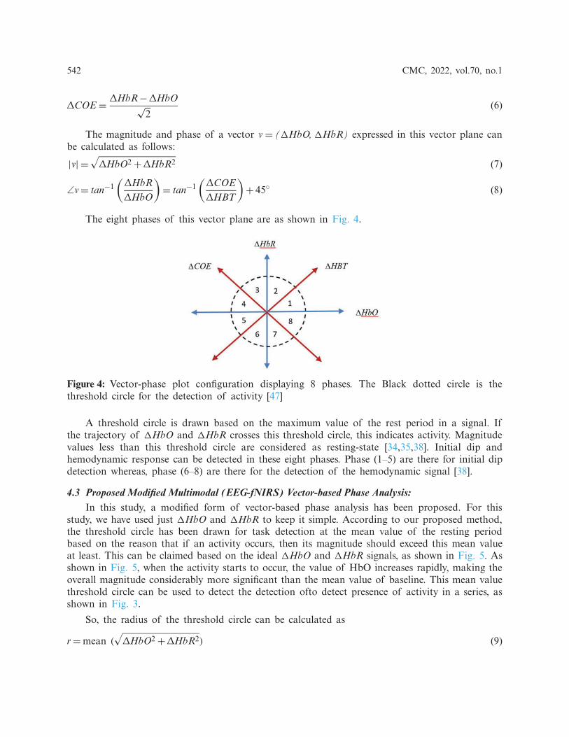
The eight phases of this vector plane are as shown in Fig. 4.
Figure 4: Vector-phase plot configuration displaying 8 phases. The Black dotted circle is thethreshold circle for the detection of activity [47]
A threshold circle is drawn based on the maximum value of the rest period in a signal. Ifthe trajectory of �HbO and �HbR crosses this threshold circle, this indicates activity. Magnitudevalues less than this threshold circle are considered as resting-state [34,35,38]. Initial dip andhemodynamic response can be detected in these eight phases. Phase (1–5) are there for initial dipdetection whereas, phase (6–8) are there for the detection of the hemodynamic signal [38].
4.3 Proposed Modified Multimodal (EEG-fNIRS) Vector-based Phase Analysis:In this study, a modified form of vector-based phase analysis has been proposed. For this
study, we have used just �HbO and �HbR to keep it simple. According to our proposed method,the threshold circle has been drawn for task detection at the mean value of the resting periodbased on the reason that if an activity occurs, then its magnitude should exceed this mean valueat least. This can be claimed based on the ideal �HbO and �HbR signals, as shown in Fig. 5. Asshown in Fig. 5, when the activity starts to occur, the value of HbO increases rapidly, making theoverall magnitude considerably more significant than the mean value of baseline. This mean valuethreshold circle can be used to detect the detection ofto detect presence of activity in a series, asshown in Fig. 3.
So, the radius of the threshold circle can be calculated as
r=mean (√
ΔHbO2 +ΔHbR2) (9)

CMC, 2022, vol.70, no.1 543
Figure 5: Ideal HbO/HbR signals constructed using two gamma function
A vector-phase diagram based on both EEG and fNIRS activity detection has been proposedin this design. So, for that purpose, we draw a circle for each trial activity completion in EEGsignal. As the activity can be detected earlier in EEG signal than fNIRS signal [41], it has beendeduced that if we draw a circle for the detected activity completion in each trial of EEG signal,then �HbO and �HbR trajectory is expected to cross that circle, if the activity is also detectedin fNIRS signal. It has been claimed that if fNIRS signal trajectory crosses the EEG-based circleof a trial, then the activity is considered as detected in hemodynamic response for that trial, too.There are 20 trials in each series of EEG signal, as can be seen in Fig. 1. EEG-based circle, foreach trial, is drawn in a way that when ith trial activity (i= 1, 2, 3,. . ., 20) is completed at timeti, then values of �HbO and �HbR at ti are used to calculate the magnitude |pi| of the circle.So, circle magnitude |pi| for ith trial can be calculated as
|pi| =√
(HbO|ti)2+ (HbR|ti)2 (10)
Figure 6: Flow chart for adopted methodology

544 CMC, 2022, vol.70, no.1
Figure 7: The ideal trajectory for modified VPA. (a) Ideal cHRF convolved with 20 impulses toform dHRF depicting 20 trials. (b) Ideal trajectory of HbO and HbR for modified VPA crossingall 20 circles one by one

CMC, 2022, vol.70, no.1 545
If any trail is detected through phase plot of EEG signal or modified VPA, then it isconsidered the presence of activity. The flowchart for the proposed methodology is shown inFig. 6. The proposed scheme can be depicted using ideal signals for both EEG and fNIRS, asshown in Fig. 7.
4.4 Ideal Trajectory for Proposed Modified Multimodal VPA:For this novel technique, we have used two gamma function to construct the ideal trajectory
of �HbO and �HbR [41] as shown in Fig. 7. Convolution of a canonical hemodynamic responsefunction (cHRF) (i.e., H(k)) with the stimulus S(k) is called designed hemodynamic responsefunction (dHRF). The cHRF is constructed using the linear combination of two gamma variantfunctions as follows:
H (k)= α1
⎡⎣ k
τ1
(ϕ1−1)e−( k
τ1)
τ1 (ϕ1− 1) !−α2
kτ2
(ϕ2−1)e−( k
τ2)
τ2 (ϕ2− 1) !
⎤⎦ (11)
where α1 represents the amplitude, τi and ϕi (i = 1, 2) are for the tuning of shape and scale,respectively and α2 represents the ratio of response to undershoot.
The dHRF can be mathematically stated as follows:
dHRF (k)=k−1∑n=0
H (n)S(k− n) (12)
where S(k) is an impulse stimulus for each trial indicating rest and activity as
S(k)={1, if k ∈ activityo, if k ∈ rest
(13)
There were 20 trials for each series for this experiment, so we have convolved 20 impulses withideal cHRF. Then it has been used to construct the modified VPA as mentioned in a previoussection. This approach for ideal trajectory has been depicted in Fig. 7.
5 Results
5.1 Hilbert Transform for Activity Detection in EEG Signals:In this novel methodology, data from selected channels of subject one was initially filtered to
retain signals only in the 0.1–15 Hz frequency range. Then data from all channels were averagedout to construct one average signal. After that, HT is used first to calculate the imaginarycomponent of the average signal using Eq. (1), as shown in Fig. 8.
For the 1st series of session 1, which is a 3-back task, 20 trials were averaged out, and theactivity portion was detected, as shown in Fig. 9. Then phase plot for the average activity signalwas constructed and compared with the phase plot of the rest signal. It can be seen from thesimultaneous phase plot of activity and rest, in Fig. 9, that the activity is contained in the rightside of the plane, indicating the x-coordinate of its centre value as greater than 0. This provesour claim for the criterion of activity detection in EEG signal that the mean should be greaterthan 0 (as mentioned in the previous section).

546 CMC, 2022, vol.70, no.1
Figure 8: HT (Eq. (1)) used to construct the imaginary component of the average EEG signal
Figure 9: (a) Twenty trials for series 1 of session 1 for subject 1 (b) Average activity signal of 20trials (c) Phase plot of average activity signal (d) Simultaneous phase plot for rest and activity

CMC, 2022, vol.70, no.1 547
Next, we have implemented the same scheme for all the trials of series 1 as shown in Fig. 10.Here too, we can see that the trajectories for all trials are contained on the right side of the planewith meanx > 0, indicating the presence of activity.
Figure 10: (a) Selection of activity portion in 5 trials for 1st series of 1st session for subject 1 isshown here. The remaining trials can be seen in supplementary material (b) Phase plots for fivetrials using HT
5.2 Modified VPA for Hemodynamic Response DetectionFor every subject, fNIRS signals of all selected channels are preprocessed and then averaged
to get an average signal. As mentioned in the previous section, the conventional VPA plotswere constructed, for series 1 of 1st session for Subject 1, with threshold circle having radius r,calculated using Eq. (9), at the mean value of resting-state as depicted in Fig. 11a. After thatEEG-based circles were constructed for 20 trials with radii calculated using Eq. (10). As shownin Fig. 11b, activity is indicated when the �HbO and �HbR trajectory crosses that trial circle.When the color of the trajectory turns green from red, it indicates that its magnitude is lesserthan |pi|, whereas when the trajectory color turns red from green, it shows that its magnitude isgreater than |pi|, indicating the presence of activity. If the activity is either detected in the EEGphase plot or in hemodynamic response, it is considered the activity.
5.3 Activation MapsFor depicting the channels’ activation, brain maps have been constructed. For this purpose,
five brain maps of each series (0-, 2- and 3-back tasks) for two subjects have been created, asshown in Fig. 12. For VPA construction with multiple circles, EEG channel closest to each fNIRSchannel has been selected. As we are working on the frontal region of the brain, so we haveselected 7 frontal EEG channels. EEG channels selected corresponding to fNIRS channels arereported in Tab. 1. The difference has been calculated for the radii of 4 trials (i.e., trial no. 5,10, 15, 20) and rest period circles, with the radius of the baseline circle individually. Using thesedifferences, brain maps have been constructed. This method can be mathematically stated as:

548 CMC, 2022, vol.70, no.1
Lij = abs(∣∣pi, j∣∣− ∣∣pbaseline, j∣∣) (14)
Lij is the difference of trial, i circle radius with baseline circle radius for each channel j. For
now, we have taken i= 5, 10, 15,&, 20 for constructing four maps, and the 5th map is constructedbased on the difference of rest period circle radius with baseline circle radius as stated below:
Lrest,j = abs(|prest, j| − |pbaseline, j|) (15)
Five maps are constructed for all three types of series (0-, 2- and 3-back tasks), as shown inFig. 12. The presence of red color shows the highest level of activation at a brain region.
Figure 11: (a) �HbO and �HbR trajectory for 1st series of 1st session for subject one signal withthreshold circle at mean of resting state. (b) EEG-based circles for 20 trials are drawn. Trajectorycolor turning green from red indicates its magnitude lesser than |pi|, whereas trajectory colorturning red from green shows that its magnitude is greater than |pi|, indicating the detection ofactivity in hemodynamic response
5.4 Average Classification AccuracyAfter using this novel classifier for all the 3 sessions for all subjects, the classification accuracy
for every series has been calculated. For each subject’s average signal, all types of tasks (0-, 2-and 3-back) were performed nine times each. The overall accuracy for this novel classifier, i.e.,91.35%, is reported and compared with the average classification accuracies for SVM, CNN andDNN in Tab. 2 [5,43].
Using this novel methodology, we have achieved a relatively higher average classificationaccuracy than other reported techniques used for this dataset and VPA with dual-threshold circles.As it can be seen from Fig. 13, the accuracy of our classifier, i.e., 91.35%, surpassed the averageaccuracies of VPA with dual circles [41], SVM, CNN, DNN [5,42,43] and ERP analysis [31] thatare 86%, 82%, 89%, 87% and 76% respectively. The average command generation time calculatedfor this dataset is 2 ± 0.1 s.

CMC, 2022, vol.70, no.1 549
Figure 12: 5 Brain Maps of 0-back test for subject 1. Remaining brain maps are provided in thesupplementary material
Table 1: EEG channels selected corresponding to fNIRS channels for the construction of brainmaps
fNIRS channel No. EEG channel selected corresponding to fNIRS channel
1(AF7) 2(AFF5h)2(AFF5) 2(AFF5h)3(AFp7) 1(Fp1)4(AF5h) 2(AFF5h)5(AFp3) 1(Fp1)6(AFF3h) 4(F1)7(AF1) 3(AFz)8(AFFz) 3(AFz)9(AFpz) 3(AFz)10(AF2) 3(AFz)11(AFp4) 19(F2)20(AFF4h) 17(Fp2)21(AF6h) 18(AFF6h)22(AFF6) 18(AFF6h)23(AFp8) 19(F2)24(AF8) 18(AFF6h)

550 CMC, 2022, vol.70, no.1
Table 2: Average Classification accuracies for 0-, 2- and 3-back tasks using modified multimodalVPA are reported and the overall average classification accuracy of the classifier is reported tobe 91.35%. Average accuracies of SVM, CNN and DNN for all subjects are also reported forcomparison [5,43]
Subjects Averageaccuracies0-back (%)
Averageaccuracies2-back (%)
Averageaccuracies3-back (%)
Overallaverageaccuracy(%)
SVMaverageaccuracies(%)
CNNaverageaccuracies(%)
DNNaverageaccuracies(%)
Subject 1 92.78 98.89 97.22 96.3 82 92 91Subject 2 86.67 99.44 98.89 95 80 73 70Subject 3 83.33 95.56 96.11 91.67 76 84 82Subject 4 71.11 73.89 80.56 75.19 76 88 86Subject 5 90.56 92.78 92.78 92.04 87 85 83Subject 6 85.56 95.56 88.89 90 71 84 81Subject 7 87.78 98.89 100 95.56 80 98 96Subject 8 95 97.78 99.44 97.41 84 94 92Subject 9 97.78 97.22 98.33 97.78 80 86 85Subject 10 78.33 60 56.67 65 91 92 89Subject 11 90 83.33 85 86.11 78 90 89Subject 12 86.11 95 87.78 89.63 91 92 89Subject 13 94.44 95.56 96.67 95.56 67 79 77Subject 14 83.33 97.78 98.89 93.33 82 94 93Subject 15 94.44 95.56 96.67 95.56 87 86 83Subject 16 97.22 99.44 97.78 98.15 93 96 95Subject 17 97.22 90.56 92.78 93.52 78 86 83Subject 18 85 85.56 83.89 84.81 84 86 85Subject 19 98.33 96.11 99.44 97.96 84 86 84Subject 20 91.11 93.33 92.22 92.22 91 94 93Subject 21 98.33 99.44 99.44 99.07 80 94 91Subject 22 86.11 95 96.11 92.41 87 94 92Subject 23 92.22 98.33 97.78 96.11 78 92 89Subject 24 83.89 81.67 77.78 81.11 93 92 90Subject 25 99.44 98.33 98.89 98.89 84 92 89Subject 26 91.67 81.11 81.11 84.63 89 92 90Complete average classification accuracy 91.35% 82% 89% 87%
6 Discussion
Many researches have been carried out up till now to improve the classification accuracy usinghybrid BCI [30,48,49]. We have used an open-source simultaneous EEG-fNIRS dataset integratedat Technische Universität Berlin [31]. n-back data for EEG and fNIRS has been used to designour novel classifier. Work had been done on this dataset previously to enhance the performanceaccuracy. Techniques such as SVM, DNN and CNN had been implemented on n-back data, andtheir accuracies were reported to be 82%, 87% and 89%, respectively [5,42,43]. VPA has been usedfor designing our classifier but in a modified form. An approach using VPA has already been

CMC, 2022, vol.70, no.1 551
implemented using dual-threshold circles, where the first circle was the conventional resting-statethreshold circle, and the second circle was an EEG-based circle drawn at the highest power of theEEG activity window. Classification accuracy using this technique was reported to be 86% [41].Intending to further improve the classification accuracy of the dataset used, we have proposed adesign where modified multimodal VPA with multiple EEG-based circles has been implemented.Average command generation time has also been calculated for this dataset which came out tobe 2 ± 0.1 s. To the best of the authors’ knowledge, this novel classifier has achieved a relativelyhigher average classification accuracy, i.e., 91.35%, as reported in Fig. 13.
65%
70%
75%
80%
85%
90%
95%Average Classification Accuracies
VPA(Dua
l thr
esho
ld cir
cles)
Figure 13: The bar chart displays the comparison of average classification accuracy of differenttechniques used for the multimodal data set [31] and VPA with dual-threshold circles
One of the advantages of this proposed classifier is that it uses VPA to channel fNIRSsignals. After rejecting the inactive channels, we are averaging the selected channels’ signals foreach subject. Therefore, inactive channels do not reduce signal activation, hence improving theperformance, making it more accurate to detect the activity in hemodynamic response.
Another advantage of this methodology is that it uses HT in a different way to constructphase plots of EEG signal trials to indicate the occurrence of activity, which is an easy andfeasible method. Detection of activity in EEG separately further enhances the performance of ourclassifier by increasing the average classification accuracy.
Another benefit of this classifier is that it does not require any training like other conventionalmachine learning and deep learning classifiers because it is a trajectory-based approach with EEGtrials-based multiple circles.
For this research, a considerably larger dataset [31] of 26 people has been used to designthis classifier compared to the dataset of 3 people used for VPA with dual threshold circles [41].This further strengthens the validation of the average classification accuracy achieved using ourclassifier.
In this study, channel activation has also been highlighted using brain maps constructed in arelatively different way than other conventional ways like t-score [41] and z-score [50]. Trial wisebrain maps have been constructed to show the presence of activity in different brain regions at

552 CMC, 2022, vol.70, no.1
different stages. The brain maps are constructed based on the difference of magnitudes of differenttrials’ circles with the magnitude of baseline circle in the vector-phase diagram.
A limitation in this research is that activity in a time span is considered as detected ifits occurrence is indicated in either EEG signal or multimodal VPA trajectory. A false positivedetection can result in some false detection of activity. To further improve the classifier, researchcan be carried out to overcome this shortcoming. In our proposed methodology, simple prepro-cessing techniques have been used, such as low pass, bandpass and high pass filters. The presenceof artifacts is still possible in the signals and can affect the resting state circle of the vector-phase diagram. So, to further improve the performance of this technique, advanced preprocessingtechniques and artifact rejection algorithms are desirable. Moreover, in this research, a comparisonbetween gender-based accuracy has not been conducted, so this investigation can also be carriedout to indicate whether the accuracy gets affected by gender or not.
7 Conclusion
In this study, a novel methodology has been proposed for enhancing average classificationaccuracy using hybrid BCI (EEG-fNIRS). For this research, a hybrid (EEG-fNIRS) dataset forn-back tasks, collected at Technische Universität Berlin was used. Hilbert transform was usedto construct phase plots for activity detection in EEG trials. A modified multimodal VPA wasdesigned with multiple threshold circles, drawn at the completion time of each trial activity inEEG signals, using �HbO and �HbR magnitudes. If the �HbO and �HbR trajectory crossed theEEG-activity-based threshold circle in the time span of each trial, then activity was consideredas detected. Thus, a modified multimodal (EEG-fNIRS) VPA was used as a classifier to get thecombined accuracy to detect activity. The collective accuracy achieved using this novel classifierwas 91.35%, relatively higher than other conventional classifiers, i.e., SVM, CNN and DNN. Theaverage command generation time computed using this technique was 2 ± 0.1 s. This researchprovides a step forward in improving the classification accuracy of state-of-the-art hybrid EEG-fNIRS BCI systems.
Acknowledgement: This research work was supported by National University of Sciences andTechnology, Pakistan.
Funding Statement: National University of Sciences and Technology supported the research.
Conflicts of Interest: The authors declare that they have no conflicts of interest to report regardingthe present study.
References[1] H. Ghonchi, M. Fateh, V. Abolghasemi, S. Ferdowsi and M. Rezvani, “Deep recurrent-convolutional
neural network for classification of simultaneous EEG-fNIRS signals,” IET Signal Processing, vol. 14,no. 3, pp. 142–153, 2020.
[2] F. Riaz, A. Hassan, S. Rehman, I. Niazi, M. Jochumsen et al., “Processing movement related corticalpotentials in EEG signals for identification of slow and fast movements,” in 2014 36th Annual Int. Conf.of the IEEE Engineering in Medicine and Biology Society, Chicago, Illinois, USA, IEEE, pp. 4908–4911,2014.
[3] A. J. Karran, T. Demazure, P. M. Leger, E. Labonte-LeMoyne, S. Senecal et al., “Toward a hybridpassive BCI for the modulation of sustained attention using EEG and fNIRS,” Frontiers in HumanNeuroscience, vol. 13, pp. 393, 2019.

CMC, 2022, vol.70, no.1 553
[4] L. F. Nicolas-Alonso and J. Gomez-Gil, “Brain computer interfaces, a review,” Sensors, vol. 12, no. 2,pp. 1211–1279, 2012.
[5] M. Saadati, J. Nelson and H. Ayaz, “Multimodal fNIRS-EEG classification using deep learning algo-rithms for brain-computer interfaces purposes,” in Int. Conf. on Applied Human Factors and Ergonomics,Cham, Springer, pp. 209–220, 2020.
[6] K. S. Hong and M. J. Khan, “Hybrid brain-computer interface techniques for improved classificationaccuracy and increased number of commands: A review,” Frontiers in Neurorobotics, vol. 11, pp. 35,2017.
[7] N. Naseer and K. S. Hong, “fNIRS-based brain-computer interfaces: A review,” Frontiers in HumanNeuroscience, vol. 9, pp. 1–15, 2015.
[8] M. Hasan, M. U. Khan and D. Mishra, “A computationally efficient method for hybrid EEG-fNIRSBCI based on the Pearson correlation,” BioMed Research International, vol. 2020, no. 3, pp. 1–13, 2020.
[9] B. Allison, T. Luth, D. Valbuena, A. Teymourian, I. Volosyak et al., “BCI demographics: How many(and what kinds of) people can use an SSVEP BCI?,” IEEE Transactions on Neural Systems andRehabilitation Engineering, vol. 18, no. 2, pp. 107–116, 2010.
[10] J. Kwon, J. Shin and C. H. Im, “Toward a compact hybrid brain-computer interface (BCI): Performanceevaluation of multi-class hybrid EEG-fNIRS BCIs with limited number of channels,” PLOS ONE, vol.15, no. 3, pp. e0230491, 2020.
[11] P. Verma, A. Heilinger, P. Reitner, J. Grünwald, C. Guger et al., “Performance investigation of brain-computer interfaces that combine EEG and fNIRS for motor imagery tasks,” in IEEE Int. Conf. onSystems, Man and Cybernetics, Bari, Italy, IEEE, pp. 259–263, 2019.
[12] M. S. Al-Quraishi, I. Elamvazuthi, S. A. Daud, S. Parasuraman and A. Borboni, “EEG-based controlfor upper and lower limb exoskeletons and prostheses: A systematic review,” Sensors, vol. 18, no. 10,pp. 3342, 2018.
[13] S. Al Kork, T. Beyrouthy, A. Kork, J. A. Korbane and M. Abouelela, “EEG mind controlled smartprosthetic arm—A comprehensive study,” in 2016 IEEE Int. Conf. onEmergingTechnologies and InnovativeBusiness Practices for the Transformation of Societies, Mauritius, IEEE, pp. 404–409, 2016.
[14] R. A. Khan, N. Naseer, N. K. Qureshi, F. M. Noori, H. Nazeer et al., “FNIRS-based neuroroboticinterface for gait rehabilitation,” Journal of Neuroengineering and Rehabilation, vol. 15, no. 1, pp. 1–17,2018.
[15] N. Naseer and K. S. Hong, “Classification of functional near-infrared spectroscopy signals correspond-ing to the right- and left-wrist motor imagery for development of a brain-computer,” NeuroscienceLetters, vol. 553, pp. 84–89, 2013.
[16] M. J. Khan, K. S. Hong, N. Naseer and M. R. Bhutta, “A hybrid EEG-fNIRS BCI: Motor imageryfor EEG and mental arithmetic for FNIRS,” in 14th Int. Conf. on Control, Automation and Systems,Seoul, Korea, IEEE, pp. 275–278, 2014.
[17] F. Riaz, A. Hassan, S. Rehman, I. K. Niazi and K. Dremstrup, “EMD-based temporal and spectralfeatures for the classification of EEG signals using supervised learning,” IEEE Transactions on NeuralSystems and Rehabilitation Engineering, vol. 24, no. 1, pp. 28–35, 2015.
[18] A. Chiarelli, P. Croce, A. Merla and F. Zappasodi, “Deep learning for hybrid EEG-fNIRS brain-computer interface: Application to motor imagery classification related content,” Journal of NeuralEngineering, vol. 15, no. 3, pp. 36028, 2018.
[19] A. P. Buccino, H. O. Keles and A. Omurtag, “Hybrid EEG-FNIRS asynchronous brain-computerinterface for multiple motor tasks,” PLOS ONE, vol. 11, no. 1, pp. e0146610, 2016.
[20] M. Jawad Khan, M. J. Hong and K. S. Hong, “Decoding of four movement directions using hybridNIRS-EEG brain-computer interface,” Frontiers in Human Neuroscience, vol. 8, pp. 244, 2014.
[21] J. Shin, K. Müller, C. Schmitz, D. W. Kim and H. J. Hwang, “Evaluation of a compact hybrid brain-computer interface system,” BioMed Research International, vol. 2017, no. 1, pp. 1–11, 2017.
[22] F. Robertson, T. S. Douglas and E. M. Meintjes, “Motion artifact removal for functional near infraredspectroscopy: A comparison of methods,” IEEE Transactions on Biomedical Engineering, vol. 57, no. 6,pp. 1377–1387, 2010.

554 CMC, 2022, vol.70, no.1
[23] S. Tak and J. C. Ye, “Statistical analysis of fNIRS data: A comprehensive review,” Neuroimage, vol.85, no. 1, pp. 72–91, 2014.
[24] J. Shin, D. W. Kim, K. R. Müller and H. J. Hwang, “Improvement of information transfer rates usinga Hybrid EEG-NIRS brain-computer interface with a short trial length: Offline and pseudo-onlineanalyses,” Sensors, vol. 18, pp. 1827, 2018.
[25] S. Lee, Y. Shin, A. Kumar, M. Kim and H. N. Lee, “Dry electrode-based fully isolated EEG/FNIRShybrid brain-monitoring system,” IEEE Transactions on Biomedical Engineering, vol. 66, no. 4, pp. 1055–1068, 2018.
[26] G. Pfurtscheller, B. Z. Allison, C. Brunner, G. Bauernfeind, T. Solis-Escalante et al., “The hybrid BCI,”Frontiers in Neuroscience, vol. 4, pp. 42, 2010.
[27] Y. Sun, H. Ayaz and A. N. Akansu, “Multimodal affective state assessment using FNIRS + EEG andspontaneous facial expression,” Brain Sciences, vol. 10, no. 2, pp. 85, 2020.
[28] Y. Liu, H. Ayaz and P. A. Shewokis, “Multisubject ‘learning’ for mental workload classification usingconcurrent EEG, FNIRS, and physiological measures,” Frontiers in Human Neuroscience, vol. 11, pp.389, 2017.
[29] R. Li, T. Potter, W. Huang and Y. Zhang, “Enhancing performance of a hybrid EEG-FNIRS systemusing channel selection and early temporal features,” Frontiers in Human Neuroscience, vol. 11, pp. 462,2017.
[30] S. K. Piper, A. Krueger, S. P. Koch, J. Mehnert, C. Habermehl et al., “A wearable multi-channel fNIRSsystem for brain imaging in freely moving subjects,” Neuroimage, vol. 85, no. Suppl. 1, pp. 64–71, 2014.
[31] J. Shin, A. Von Lühmann, D. W. Kim, J. Mehnert, H. J. Hwang et al., “Simultaneous acquisition ofEEG and NIRS during cognitive tasks for an open access dataset,” Scientific Data, vol. 5, no. 1, pp.1–16, 2018.
[32] A. Zafar and K. S. Hong, “Neuronal activation detection using vector phase analysis with dualthreshold circles: A functional near-infrared spectroscopy study,” International Journal of Neural Systems,vol. 28, no. 10, pp. 1850031, 2018.
[33] H. Nazeer, N. Naseer, R. A. Khan, F. M. Noori, N. K. Qureshi et al., “Enhancing classificationaccuracy of FNIRS-BCI using features acquired from vector-based phase analysis,” Journal of NeuralEngineering, vol. 17, no. 5, pp. 56025, 2020.
[34] T. Kato, Vector-based approach for the detection of initial dips using functional near-infrared spec-troscopy. In: Neuroimaging-Structure, Function and Mind. London, UK: IntechOpen, 2019.
[35] K. S. Hong and N. Naseer, “Reduction of delay in detecting initial dips from functional near-infraredspectroscopy signals using vector-based phase analysis,” International Journal of Neural System, vol. 26,no. 3, pp. 1650012, 2016.
[36] A. Zafar and K. S. Hong, “Detection and classification of three-class initial dips from prefrontalcortex,” Biomedical Optics Express, vol. 8, no. 1, pp. 367–383, 2017.
[37] K. Yoshino and T. Kato, “Vector-based phase classification of initial dips during word listening usingnear-infrared spectroscopy,” Neuroreport, vol. 23, no. 16, pp. 947–951, 2012.
[38] K. Hong and A. Zafar, “Existence of initial dip for BCI: An illusion or reality,” Frontiers inNeurorobotics, vol. 12, pp. 69, 2018.
[39] M. Sano, S. Sano, N. Oka, K. Yoshino and T. Kato, “Increased oxygen load in the prefrontal cortexfrom mouth breathing: A vector-based near-infrared spectroscopy study,” Neuroreport, vol. 24, no. 17,pp. 935–940, 2013.
[40] K. S. Hong, M. J. Khan and M. J. Hong, “Feature extraction and classification methods for hybridfNIRS-EEG brain-computer interfaces,” Frontiers in Human Neuroscience, vol. 12, pp. 246, 2018.
[41] M. J. Khan, U. Ghafoor and K. S. Hong, “Early detection of hemodynamic responses using EEG: Ahybrid EEG-FNIRS study,” Frontiers in Human Neuroscience, vol. 12, pp. 479, 2018.
[42] U. Asgher, K. Khalil, Y. Ayaz, R. Ahmed and M. J. Khan, “Classification of mental workload (MWL)using support vector machines (SVM) and convolutional neural networks (CNN),” in 3rd Int. Conf. onComputing, Mathematics and Engineering Technologies, Sukkur, Pakistan, IEEE, pp. 1–6, 2020.

CMC, 2022, vol.70, no.1 555
[43] M. Saadati, J. Nelson and H. Ayaz, “Convolutional neural network for hybrid FNIRS-EEG mentalworkload classification,” in Advances in Intelligent Systems and Computing. vol. 953. Berlin, Germany:Springer, pp. 221–232, 2020.
[44] W. De Clercq, P. Lemmerling, W. Van Paesschen and S. Van Huffel, “Characterization of interictal andictal scalp EEG signals with the Hilbert transform,” in Proc. of the 25th Annual Int. Conf. of the IEEEEngineering in Medicine and Biology Society (IEEE Cat. No. 03CH37439), Cancun, Mexico, IEEE, vol.3, pp. 2459–2462, 2003.
[45] K. Yoshino, N. Oka, K. Yamamoto, H. Takahashi and T. Kato, “Correlation of prefrontal corticalactivation with changing vehicle speeds in actual driving: A vector-based functional near-infraredspectroscopy study,” Frontiers in Human Neuroscience, vol. 7, pp. 895, 2013.
[46] N. Oka, K. Yoshino, K. Yamamoto, H. Takahashi, H. S. Li et al., “Greater activity in the frontalcortex on left curves: A vector-based fNIRS study of left and right curve driving,” PLOS ONE, vol.10, no. 5, pp. e0127594, 2015.
[47] H. Nazeer, N. Naseer, R. A. Khan, F. M. Noori, N. K. Qureshi et al., “Enhancing classificationaccuracy of FNIRS-BCI using features acquired from vector-based phase analysis,” Journal of NeuralEngineering, vol. 17, no. 5, pp. 56025, 2020.
[48] S. Fazli, J. Mehnert, J. Steinbrink, G. Curio and A. Villringer, “Enhanced performance by a hybridNIRS-EEG brain computer interface,” Neuroimage, vol. 59, no. 1, pp. 519–529, 2012.
[49] B. Koo, H. G. Lee, Y. Nam, H. Kang, C. S. Koh et al., “A hybrid NIRS-EEG system for self-pacedbrain computer interface with online motor imagery,” Journal of Neuroscience Methods, vol. 244, pp.26–32, 2015.
[50] H. Matsuda, S. Mizumura, T. Nagao, T. Ota, T. Iizuka et al., “An easy Z-score imaging system fordiscrimination between very early Alzheimer’s disease and controls using brain perfusion SPECT in amulticentre study,” Nuclear Medicine Communications, vol. 28, no. 3, pp. 199–205, 2021.


![Functional Near-Infrared Spectroscopy (fNIRS) during Apnoeabiosignalsplux.com/downloads/docs/technical-notes/... · A functional near-infrared spectroscopy (fNIRS) sensor [7] uses](https://static.fdocuments.net/doc/165x107/5fbd4343fe93b80102432136/functional-near-infrared-spectroscopy-fnirs-during-a-functional-near-infrared.jpg)