Helo Movement Tiedown Procedures
108
SDDCTEA PAMPHLET 55-21
-
Upload
muzafar-shah-mosam-shah -
Category
Documents
-
view
201 -
download
17
description
Mov Plan Data
Transcript of Helo Movement Tiedown Procedures
SDDCTEA PAMPHLET 55-21
SDDCTEA PAMPHLET 55-21
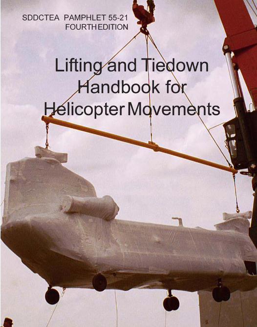
LIFTING AND TIEDOWN
HANDBOOK FOR
HELICOPTER MOVEMENTS
FOURTH EDITION July 2006
(Electronically Revised August 2012)
Ron Belaska
______________________________________________________ MILITARY SURFACE DEPLOYMENT AND DISTRIBUTION COMMAND
TRANSPORTATION ENGINEERING AGENCY SCOTT AIR FORCE BASE, ILLINOIS
FOURTH EDITION SDDCTEA PAMPHLET 55-21
ii
Director Military Surface Deployment and Distribution Command Transportation Engineering Agency ATTN: SDDCTEA - DPE (R. Belaska) 1 Soldier Way, Bldg 1900W Scott AFB, IL 62225
Telephone: DSN 770-5254, 618-220-5254, or 1-800-722-0727 FAX: DSN 770-5551 or 618-220-5551 E-mail: [email protected]
Make requests for additional copies or latest updated copy of these references can be downloaded from our website: http://www.tea.army.mil/pubs/pubs_order.htm
This book is part of the series started with MTMCTEA PAM 55-19, Tiedown
Handbook for Rail Movements. The books in the series are:
Handbooks for Military Movements PAM 55-19, Tiedown Handbook for Rail Movements PAM 55-20, Tiedown Handbook for Truck Movements PAM 55-21, Lifting and Tiedown Handbook for Helicopter Movements PAM 55-22, Marine Lifting and Lashing Handbook PAM 55-23, Tiedown Handbook for Containerized Movements PAM 55-24, Vehicle and Equipment Preparation Handbook for Fixed Wing Air
Movements
Planning and User’s Guide
PAM 70-1 Transportability for Better Deployability PAM 700-2 Logistics Handbook for Strategic Mobility Planning PAM 700-4 Vessel Characteristics for Shiploading PAM 700-5 Deployment Planning Guide PAM 700-6 Large, Medium Speed, Roll-On/Roll-Off Ships Users’ Manual PAM 700-7 Fast Sealift Ship Users’ Manual
FOURTH EDITION SDDCTEA PAMPHLET 55-21
iii
Preface
This is the fourth edition of the pamphlet. It supersedes the third edition, Lifting and Tiedown Handbook for Helicopter Movements (June 2002). However, copies of the older editions still have value, and you may continue to use any copies you have. Between printings, the most current information can always be found on line at www.tea.army.mil/pubs. For this edition, we have updated all the information and added information on lifting the CH-47 and AH-64 helicopters.
The purpose of this pamphlet is to aid the shipping unit and to provide general
guidelines for the helicopter transport. This pamphlet contains general information concerning lifting and tiedown
procedures on U.S. military helicopters. Helicopters are extremely fragile, high-dollar materiel; extreme care must be taken to ensure proper safe transport.
This pamphlet provides general guidance only. All preparation, lifting, and tiedown
must be in accordance with the Preparation for Shipment Manual for the helicopter being shipped. All ground handling of helicopters must be supervised by trained aviation personnel. All rigging of helicopters for lifting must be directed by aviation personnel, trained and on unit orders to supervise rigging operations. Helicopter models vary; therefore, it is the responsibility of the deploying unit to provide appropriate technical manuals and to prepare and secure the proper equipment for transport of its aircraft.
TEA welcomes comments and recommendations. Forward comments to the above
point of contact: Ron Belaska on page ii.
FOURTH EDITION SDDCTEA PAMPHLET 55-21
iv
NOTES
This pamphlet is unofficial and provides only a quick reference and familiarization in the transport of the U.S. military helicopters. Although it has been staffed extensively throughout the aviation community, some modifications and helicopter design variations may not appear in this reference. Official procedures for the preparation, disassembly/reassembly, lifting, and tiedown of U.S. military helicopters may be obtained from Headquarters, U.S. Army Aviation and Missile Command (AMCOM), ATTN: AMSAM-MMC-MM-DT, Sparkman Building 5302, 2nd Floor, Redstone Arsenal, AL 35898-5230, DSN 645-8281 or (256) 955-8281, or [email protected]. Additionally, you can download the complete helicopter shipping manuals from the following website: http://www.logsa.army.mil/etms/online.htm
The significant changes in this electronic update are on Page B-13, in the Notes section the forward and center cargo hook tiedown ratings have been changed. Also, on Page E-11 a third tiedown was added to FS 450 tiedown provision. This electronic update still refers to using shrink wrap for marine or vessel transport. However, shrink wrap is not authorized for marine transport. Due to the extensive changes required to delete shrink wrap for marine transport is was not included in this electronic update, but is being incorporated in the Fifth Edition of SDDCTEA PAMPHLET 55-21 which is currently being written. The Fifth Edition should be released by July 2013.

FOURTH EDITION SDDCTEA PAMPHLET 55-21
v
Lifting and Tiedown Handbook for Helicopter Movements
CONTENTS
Section Page I. General Guidelines ............................................................................................ 1
II. Definitions ......................................................................................................... 3
III. Required Loading Equipment ........................................................................... 4
A. Disassembly of Aircraft ............................................................................... 4 B. Additional Equipment Required for Assembly of Aircraft after Debarkation ....................................................................... 5
IV. Planning and Preparation for Shipment ............................................................. 6
A. Planning ....................................................................................................... 6 B. Shipping Configuration ................................................................................ 6 C. Shipping Responsibility ............................................................................... 7 D. Shipping Precautions ................................................................................... 7 E. Preparation Guidelines ................................................................................. 8 F. Helicopter Preservation for Shipment .......................................................... 9
V. General Lifting Procedures ................................................................................ 10
VI. General Tiedown Procedures ............................................................................. 11
A. General ........................................................................................................ 11 B. Marine Shipping .......................................................................................... 12 C. Highway Shipping ....................................................................................... 15 D. Air Shipping ................................................................................................ 15
VII. Intransit Care for Marine Shipment ............................................................. 18

FOURTH EDITION SDDCTEA PAMPHLET 55-21
vi
Appendixes Page
A UH-1 Iroquois ...................................................................................... A-1
B CH-47 Chinook ..................................................................................... B-1
C OH-58 Kiowa Warrior .......................................................................... C-1
D UH-60 Black Hawk ............................................................................. D-1
E AH-64 Apache ...................................................................................... E-1
Bibliography and Index Located at the end of the handbook
FOURTH EDITION SDDCTEA PAMPHLET 55-21
1
Section I. General Guidelines A. This pamphlet provides users with general guidance for the preparation for shipment, lifting, and tiedown of U.S. military helicopters during transport. It contains basic information from a variety of sources and from experience gained from loadouts and live deployments.
B. Because of the complexity of helicopter preparation and loading procedures, predeployment planning is essential. Transport mode assignment should be identified as early as possible to allow adequate planning. The shipping configuration should minimize disassembly. This helps reduce assembly and test flight requirements upon arrival at the port of debarkation (POD).
C. Helicopters loaded onto a transportation asset must be secured with chains or straps to counteract longitudinal, lateral, and vertical forces. It is essential that chains or straps be tightened only enough to remove slack; over tightening of chains or straps can result in structural damage to the helicopter. If using straps for restraint, only use straps with the standard short or short and wide ratchet handles. DO NOT buy straps with the long wide ratchet handle. Tiedown provisions can be easily damaged when using ratchet handles with long wide handles. Bridging (blocking and bracing) of helicopters is not authorized. All aircraft preparation, lifting, and tiedown must be in accordance with the appropriate helicopter Preparation for Shipment Manuals and the specific Loading Instructions Manuals for military aircraft (fixed-wing air shipments only). Preparation for Shipment Manuals and Loading Instructions Manuals are listed in the Bibliography at the back of this pamphlet and the Preparation for Shipment Manuals can be accessed from the following website: http//www.logsa.army.mil/etms/online.htm.
D. The following “guidelines” apply to all types of helicopters:
1. Personnel
Shipment of a helicopter requires at least two aircraft maintenance personnel, qualified in the lifting and tiedown of military helicopters.
2. Handling
Helicopter ground handling must be accomplished only by qualified aviation personnel, preferably from the deploying unit.
FOURTH EDITION SDDCTEA PAMPHLET 55-21
2
3. Packaging
All rotating helicopter parts such as main and tail rotors must be positively secured to prevent them from moving while loading or during shipment. All removed components must be preserved and packed for transport in accordance with the appropriate Preparation for Shipment Manual.
4. Marine Shipment
Helicopters shipped by marine mode must be stowed below deck. Careful stow planning is required to ensure that larger aircraft will fit and can be maneuvered below deck. The overall height and width is of the most concern. Weather deck shipment is a high-risk option and should be considered only as a last resort. This is particularly true of UH-1 and OH-58 series helicopters because of inadequate tiedown provisions. Rotor blades must be removed from all aircraft shipped above deck. The corrosive effects of above deck transport must be considered. The shrink wrap usually does not stand up to the weather conditions seen above deck.
5. Air Shipment
Helicopters shipped by military fixed wing aircraft are not normally shrink wrapped prior to loading. Because of low clearances beneath some helicopters, particularly AH-64 helicopters, plywood approach shoring will be required to reduce the ramp angle during loading. The shipping unit is responsible for providing shoring.
6. Highway Shipment
Helicopters are not normally shipped by highway transport during deployments; however, this mode is typically used for recovery operations.
7. Responsibility
Aircraft maintenance personnel must provide technical assistance and supervise lifting and tiedown (lashing) of the helicopter on its transporter. During transport, the helicopter is the responsibility of the shipping unit.
FOURTH EDITION SDDCTEA PAMPHLET 55-21
3
Section II. Definitions
FSS (Fast Sealift Ship) - Fast (27 kts) Military Sealift Command (MSC) cargo ships capable of roll-on/roll-off loading and equipped with on-board cranes and self-contained ramps.
LMSR (Large Medium Speed Roll-on/Roll-off) - Medium speed (24 kts) cargo ship capable of roll-on/roll-off loading and equipped with on-board cranes and self-contained stern and side ramps.
Tactical Highway Transport - A short haul (not to exceed 100 miles) shipment by military M270A1 semitrailer.
Logistical Highway Transport - A long haul (in excess of 100 miles) shipment by standard commercial flatbed trailer with air-ride suspension.
Reduced for Sealift Operational - Helicopters reduced to the required minimum to facilitate rapid deployment, the tail pylon will remain intact and the main rotor blades may be folded.
Reduced for Sealift - Helicopters reduced to facilitate rapid deployment, the tail pylon must be folded and the main rotor blades may be folded (except for the UH-1).
CAGE - A number used by the government to identify the manufacturer of a particular part.
F.S. (Fuselage Station) - Location on the helicopters fuselage measured in inches from the nose of the helicopter or other arbitrary datum point.
FOURTH EDITION SDDCTEA PAMPHLET 55-21
4
Section III. Required Loading Equipment
This is an outline of the resources required for shipment that must be provided at the port of embarkation (POE) through a combination of Port Support Activity (PSA) and deploying unit assets. Coordination is essential to ensure the availability of assets, manpower, equipment, and materials at the POE and is the responsibility of the deploying unit. Availability of the following must be considered: A. Disassembly of Aircraft
1. Aircraft shipping and maintenance manuals.
2. Tow bars, towing bridles, and vehicles.
3. Crane trucks, self-propelled crane aircraft maintenance and positioning (SCAMP), and forklifts.
4. Fuel truck (to fuel/defuel aircraft).
5. Maintenance stands.
6. Generator Power Unit (GPU) or Auxiliary Ground Power Unit (AGPU).
7. Aircraft covers (flyaway gear).
8. Grounding cables.
9. Shrink wrap equipment and materials.
10. General mechanics tool sets and special tools required for aircraft disassembly /assembly.
11. Fire fighting equipment.
12. Fire truck (coordinate through port facility).
13. Combustible gas indicator with certified operator (coordinate through port facility).
14. Restraint devices and tiedown provisions.
FOURTH EDITION SDDCTEA PAMPHLET 55-21
5
15. Lifting devices, special slings, adapters, taglines (rope) and other hoisting equipment as specified in the aircraft manual.
16. Main rotor blade boxes (for removed rotor blades).
17. Main rotor blade slings (to remove main rotor blades).
18. Blade folding tools/fixture.
19. Ground handling wheels.
20. Armament tool sets.
21. Rocket pod/missile launcher containers.
22. Crates for removed components. Tags and zip-lock bags are useful for storing hardware and some components. Plastic bubble wrap is needed to protect sensitive components that must be removed.
23. Wheel chocks.
24. Spare tires for helicopters.
25. Cherry picker or similar personnel lifting device for lifting personnel for helicopter rigging for lift-on-lift-off operations.
B. Additional equipment required for assembly of aircraft after debarkation
1. Bore sight equipment.
2. Pitot static system tester.
3. Appropriate tracking and balancing equipment or the Army Vibration Analyzer (AVA). Ground handling and lifting devices must accompany the aircraft and be readily accessible for unloading at the POD.
FOURTH EDITION SDDCTEA PAMPHLET 55-21
6
Section IV. Planning and Preparation for Shipment A. Planning Predeployment planning is essential to a successful deployment of aviation assets. Upon receipt of the port call, the deploying unit transportation officer should proceed as follows:
1. Contact the designated staging area commander at the POE.
2. Provide the POE point of contact with the characteristics of the equipment to be shipped (dimensions and weight) and any tactical consideration impacting the shipping configuration of the helicopters.
3. Coordinate POE support requirements directly with PSA only after direct coordination has been made with the POE terminal/port commander.
Note: Port support for Forces Command (FORSCOM) aviation assets can be provided by selected elements of the Army National Guard (ARNG), Aviation Classification and Repair Activity Depots (AVCRADs) through the Headquarters, Aviation Depot Maintenance Roundout Unit (HQ ADMRU). These elements can provide a wide range of services to deploying aviation units to include but not limited to aircraft preparation, preservation (to include application of shrink film), maintenance support through Aviation Intermediate Maintenance (AVIM), and technical assistance on aircraft upload and tiedown. Request ADMRU support through CNGB, ATT; NGB-AVS, 111 S. George Mason Drive, Arlington, VA, 22204-1382, telephone (DSN) 327-7700 to Commander, HQ ADMRU, Bldg E4305 (Edgewood Area), Aberdeen Proving Ground, MD, 21010-5401, telephone DSN 584-3395/3495/2015, (FAX) 2044. PSAs for other MACOMs are assigned by the MACOM deployment regulation (FORSCOM/ARNG 55-1, Unit Movement Planning, dated 1 Mar 00). Timely notification and coordination is required to ensure adequate support.
B. Shipping Configuration
Helicopter configuration must be in accordance with the shipping manual. The configuration required for helicopter shipment will be determined by the following:
1. Mode of transportation. 2. Type of transporter.
3. Tactical deployment.
FOURTH EDITION SDDCTEA PAMPHLET 55-21
7
For tactical deployments, disassembly should be kept to an absolute minimum to minimize assembly/depreservation time at Port of Debarkation (POD).
C. Shipping Responsibility
Army helicopters must be preserved and prepared for shipment in accordance with the applicable Preparation for Shipment Manual. The shipper/deploying unit prepares the helicopters for shipment as follows:
1. Provide equipment and manpower.
2. Requisition the required shrink wrap.
3. Package removed parts and equipment.
4. Preserve the helicopters as required in the shipping manual.
5. Adjust fuel level per the recommended fuel system preparation.
6. For marine mode, apply heat shrink film protective covering materials.
7. Arrange for transport equipment.
8. Assist staging area personnel in the loading and tiedown of the helicopters. Supply of the material is to be accomplished through the normal supply channel.
D. Shipping Precautions
1. For marine modes, shipment of helicopters on the weather deck of a vessel isa high-risk option, structurally and because of the corrosive environment, and is not recommended.
2. OH-58 and UH-1 series helicopters have deficient tiedown provisions. Special tiedown procedures have been developed to compensate for these deficiencies.
3. Do not push UH-60 or AH-64 helicopters up the ramp. Tow only.
4. Use towing bridles as required.
5. Avoid stepping on tiedown chains or straps to avoid damage to the helicopter restraint provisions.
FOURTH EDITION SDDCTEA PAMPHLET 55-21
8
6. Make sure lifting and/or tiedown provisions are not covered up by shrink wrap.
7. Do not over tension tiedown chains or straps as damage may occur to tiedown provisions.
8. Do not run chains or straps through the provisions. Attach each chain or strap directly to the provisions. The only exception to this is when straps are used on the FS 120 tiedowns on the AH-64. See page E-13 for more information.
E. Preparation Guidelines
1. Color code rotating components (blades, controls, etc.) prior to removal.
2. Tag all removed components.
3. Bag, tag, and attach removed hardware to aircraft or removed component as appropriate.
4. Preserve and package removed components in special reusable containers or crates as appropriate.
5. Mark each container, crate, and helicopter with contents, gross weight, and center of gravity.
6. Adjust fuel level (see fuel system preservation guidance in Preparation for Shipment Manual).
7. Install flyaway gear (intake covers, exhaust covers, pitot tube covers, etc.).
8. Use wing walkers and brakemen for all towing and ground handling.
9. Provide technical assistance to the staging area commander. Establish a rapport with the commander and a unit technical focal point.
Aviation units should arrive at POE with the necessary equipment available for both roll-on/roll-off (RORO) loading and lifting. Refer to appropriate helicopter Preparation for Shipment Manual (see Bibliography at end of this pamphlet) for more detailed information on preparing the helicopters for shipment.
FOURTH EDITION SDDCTEA PAMPHLET 55-21
9
F. Helicopter Preservation for Shipment
1. Besides assets, manpower, equipment, and materials needed at the POE (listed for air/marine shipment), all helicopters must be preserved in accordance with the Preparation for Shipment Manual. Preservation for vessel shipment is similar to preservation for intermediate storage. Refer to appropriate aircraft Preparation for Shipment Manual for helicopter preservation procedures.
2. The extent of preservation required for the fuel system is identified in the appropriate technical manuals.
3. Shrink wrap materials, equipment, installation instructions, and manpower requirements are provided in appendix G of Preparation for Shipment Manuals. Apply heat shrink wrap protective covering on all military helicopters being shipped via the marine mode regardless of the location of the helicopter on the vessel. Protective covering must also be applied to those helicopters being shipped by tractor-trailer on highways. The level of protection required for short-distance shipments will be determined by the shipper. Heat shrink wrap is not normally applied for air shipments.
WARNING: When applying shrink wrap, make sure lifting and tiedown provisions are exposed and accessible
FOURTH EDITION SDDCTEA PAMPHLET 55-21
10
Section V. General Lifting Procedures
The following lifting guidelines are used for highway and marine transport.
A. The lifting procedures published in this pamphlet summarize the procedures in the Preparation for Shipment manual.
B. Inspect all lifting equipment prior to movement to the staging area.
C. Replace all defective equipment; inspect equipment again prior to use.
D. Make sure shrink wrap does not cover up lifting provisions.
E. Helicopters must be rigged for lifting only by properly trained aircraft maintenance personnel on unit orders to supervise lifting operations, using the appropriate preparation for Shipment Manuals.
F. Tag lines must be attached to each helicopter at a minimum of three (AH-64, UH-60 series) or four points (all others).
G. Ground handling and lifting devices must accompany each aircraft shipment and must be readily accessible for unloading.
H. For UH-1 and AH-64 helicopters, or other helicopters without longer, multileg, slings, attach a short pendant (3'- 5') below the crane hook. Pendant will allow some clearance if the hook is not centered on the main rotor mast for connection.
FOURTH EDITION SDDCTEA PAMPHLET 55-21
11
Section VI. General Tiedown Procedures
The procedures in this section are to be used as a general guide only.
A. General
1. The tiedown procedures published in this pamphlet summarize the procedures in the Preparation for Shipment manual.
2. Inspect all tiedown equipment, ensuring tiedown provisions are installed, prior to movement to the staging area.
3. Aircraft maintenance personnel must supervise tiedown (lashing) of helicopters. The shipping unit provides technical assistance on the tiedown of their aircraft.
4. Chock all wheels as required.
5. Maintain at least 12 to 18 inches clearance between helicopters and bulkheads.
6. Make sure shrink wrap does not cover up tiedown provisions.
7. Attach chains or straps directly to provisions. Do not run chains or straps through the provisions.
8. Blocking and bracing (shoring) between helicopters is not authorized.
9. Ensure that tiedown chains or straps do not chafe on helicopters.
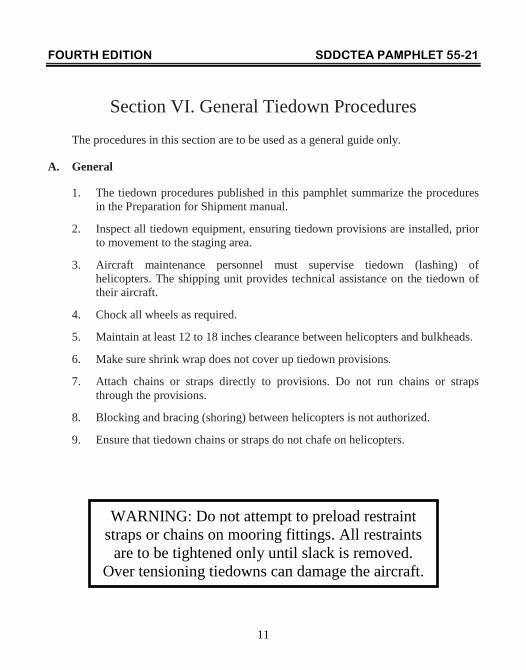
WARNING: Do not attempt to preload restraint
straps or chains on mooring fittings. All restraints are to be tightened only until slack is removed.
Over tensioning tiedowns can damage the aircraft.
FOURTH EDITION SDDCTEA PAMPHLET 55-21
12
B. Marine Shipping
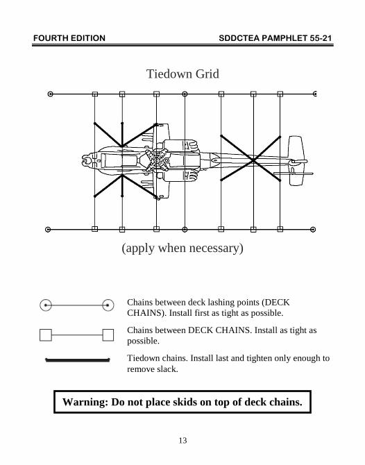
Tiedown chain and strap angles on helicopters are critical. The number of tiedown points on some vessels is very limited. When tiedown points are not sufficient, provide helicopter tiedown points by running vessel lashing gear (chains) between vessel tiedown points. Connect additional lashing gear, as required, to provide a grid on the vessel deck that will provide tiedown points at the required angles. These chains should be as tight as possible and in place before any helicopter restraint devices are installed. Follow the instructions below and proceed as illustrated on page 13.
1. Stow helicopters as required inside the vessel.
2. Install wheel chocks as required.
3. If required, connect chains (vessel's lashing gear with a breaking strength of at least 70,000 pounds) between deck lashing points as appropriate. Make these chains as tight as possible. Connect chains (with a breaking strength of at least 70,000 pounds) between “deck chains” as required to provide tiedown points. Make these chains also as tight as possible.
4. Install helicopter restraints (chains or straps). They are to be tightened only enough to remove slack. If restraint devices are too slack, the helicopters will be damaged due to movement. Over-tightening will also cause structural damage. Special procedures have been developed for OH-58 and UH-1 series helicopters because of inadequate tiedown provisions.
5. Dunnage is not required or authorized as a restraint procedure for helicopters. Helicopters must be tied down with straps and chains only.
6. The Aviation and Missile Command has approved the use of polyester straps for marine transport of helicopters. It is MTMC policy that polyester straps be used for tying down helicopters on marine vessels. Terminal commanders are responsible for ensuring that the straps are available and are properly installed. Guidance for the purchase and use of polyester straps for marine transport of helicopters is shown on page 14.
FOURTH EDITION SDDCTEA PAMPHLET 55-21
13
Tiedown Grid
(apply when necessary)
Chains between deck lashing points (DECK CHAINS). Install first as tight as possible.
Chains between DECK CHAINS. Install as tight as possible.
Tiedown chains. Install last and tighten only enough to remove slack.
Warning: Do not place skids on top of deck chains.
FOURTH EDITION SDDCTEA PAMPHLET 55-21
14
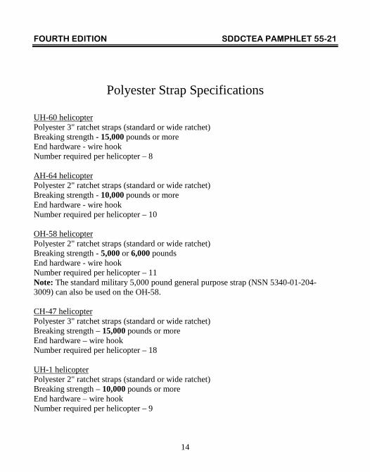
Polyester Strap Specifications
UH-60 helicopter Polyester 3" ratchet straps (standard or wide ratchet) Breaking strength - 15,000 pounds or more End hardware - wire hook Number required per helicopter – 8 AH-64 helicopter Polyester 2" ratchet straps (standard or wide ratchet) Breaking strength - 10,000 pounds or more End hardware - wire hook Number required per helicopter – 10 OH-58 helicopter Polyester 2" ratchet straps (standard or wide ratchet) Breaking strength - 5,000 or 6,000 pounds End hardware - wire hook Number required per helicopter – 11 Note: The standard military 5,000 pound general purpose strap (NSN 5340-01-204- 3009) can also be used on the OH-58. CH-47 helicopter Polyester 3" ratchet straps (standard or wide ratchet) Breaking strength – 15,000 pounds or more End hardware – wire hook Number required per helicopter – 18 UH-1 helicopter Polyester 2" ratchet straps (standard or wide ratchet) Breaking strength – 10,000 pounds or more End hardware – wire hook Number required per helicopter – 9
FOURTH EDITION SDDCTEA PAMPHLET 55-21
15
C. Highway Shipping
When transported on highways, helicopters must be loaded on trailers that have air ride suspension and the ability to support a 20,000 pound minimum load. Air ride suspension is required because transport on semitrailers with spring suspension may cause damage to the helicopter. The tractor should also have air ride suspension and be capable of pulling a minimum load of 20,000 pounds. For tactical transport of helicopters (distance less than 100 miles) an M270A1 military trailer may be used along with a 5-ton truck tractor. For logistical transport (distance greater than 100 miles) a commercial trailer with a maximum height of 30 inches should be used. For commercial trucks with air ride suspension, trailer ballast is required for the air ride suspension to function properly. The amount of weight required will vary due to the helicopter's weight when configured for transport and the length of the trailer. Permits for highway transport and special routing may be required when the helicopter exceeds the legal height, width or length limits. Shipping units should contact the Unit Movement Officer or Installation Transportation Officer to obtain permits. Tiedown devices are to be secured tight enough to remove slack in the chain or strap. Over tightening will cause damage to the helicopter.
D. Air Shipping
For air shipment, the center of gravity and exact weight must be computed for each helicopter so the center of gravity of the loaded aircraft can be determined. Incorrect balance locations or inaccurate shipping weights will endanger loaded helicopters, crew members and cargo. Straps are not approved for air transport and should not be used. Use only MB-1 and MB-2 chains.
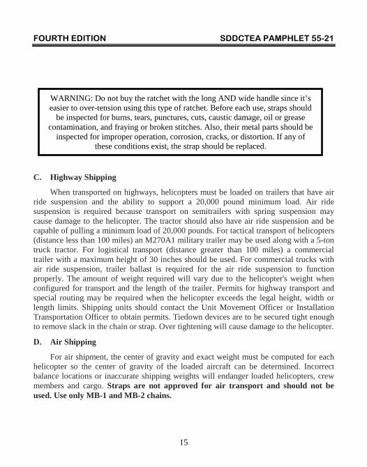
WARNING: Do not buy the ratchet with the long AND wide handle since it’s easier to over-tension using this type of ratchet. Before each use, straps should
be inspected for burns, tears, punctures, cuts, caustic damage, oil or grease contamination, and fraying or broken stitches. Also, their metal parts should be
inspected for improper operation, corrosion, cracks, or distortion. If any of these conditions exist, the strap should be replaced.
FOURTH EDITION SDDCTEA PAMPHLET 55-21
16
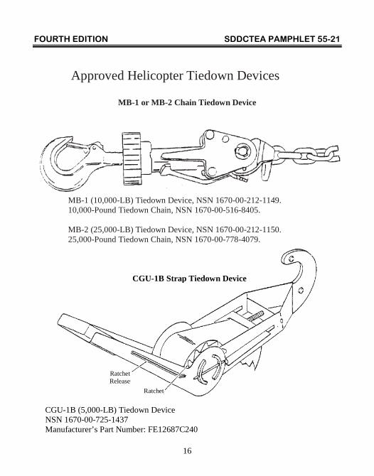
Approved Helicopter Tiedown Devices
MB-1 or MB-2 Chain Tiedown Device
MB-1 (10,000-LB) Tiedown Device, NSN 1670-00-212-1149. 10,000-Pound Tiedown Chain, NSN 1670-00-516-8405. MB-2 (25,000-LB) Tiedown Device, NSN 1670-00-212-1150. 25,000-Pound Tiedown Chain, NSN 1670-00-778-4079.
CGU-1B Strap Tiedown Device
CGU-1B (5,000-LB) Tiedown Device NSN 1670-00-725-1437 Manufacturer’s Part Number: FE12687C240
Ratchet
Ratchet Release
FOURTH EDITION SDDCTEA PAMPHLET 55-21
17
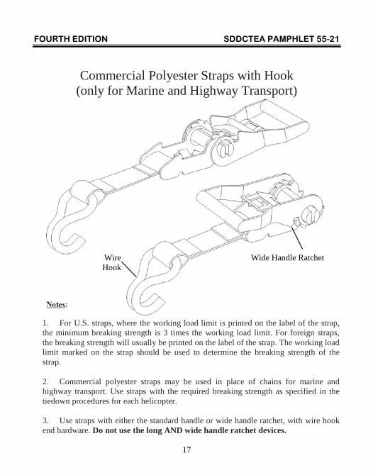
Commercial Polyester Straps with Hook (only for Marine and Highway Transport)
1. For U.S. straps, where the working load limit is printed on the label of the strap, the minimum breaking strength is 3 times the working load limit. For foreign straps, the breaking strength will usually be printed on the label of the strap. The working load limit marked on the strap should be used to determine the breaking strength of the strap. 2. Commercial polyester straps may be used in place of chains for marine and highway transport. Use straps with the required breaking strength as specified in the tiedown procedures for each helicopter. 3. Use straps with either the standard handle or wide handle ratchet, with wire hook end hardware. Do not use the long AND wide handle ratchet devices.
Wide Handle Ratchet Wire Hook
FOURTH EDITION SDDCTEA PAMPHLET 55-21
18
Section VII. Intransit Care for Marine Shipments
It is recommended that two aviation personnel accompany aircraft on vessel shipment to perform supercargo duties. Duties of the supercargo include the following:
A. Providing security for aircraft.
B. Inspecting heat shrink wrap covers daily for damage and repairing as necessary.
C. Making repairs to shrink wrap and draining any condensation as required.
D. Inspecting for fluid leaks - particularly fuel.
E. Maintaining proper tiedown tension.
F. Maintaining proper tire and strut inflations.
G. Rigging helicopters and providing technical supervision for offloading.

FOURTH EDITION SDDCTEA PAMPHLET 55-21
19
Notes
FOURTH EDITION SDDCTEA PAMPHLET 55-21
A-1
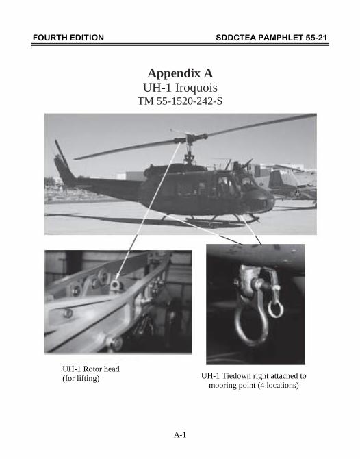
Appendix A UH-1 Iroquois
TM 55-1520-242-S
UH-1 Rotor head (for lifting) UH-1 Tiedown right attached to
mooring point (4 locations)
FOURTH EDITION SDDCTEA PAMPHLET 55-21
A-2
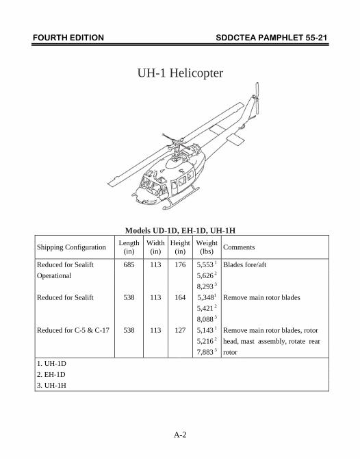
UH-1 Helicopter
Models UD-1D, EH-1D, UH-1H
Shipping Configuration Length (in)
Width (in)
Height (in)
Weight (lbs) Comments
Reduced for Sealift 685 113 176 5,553 1 Blades fore/aft Operational 5,626 2 8,293 3 Reduced for Sealift 538 113 164 5,3481 Remove main rotor blades 5,421 2 8,088 3 Reduced for C-5 & C-17 538 113 127 5,143 1 Remove main rotor blades, rotor 5,216 2 head, mast assembly, rotate rear 7,883 3 rotor 1. UH-1D 2. EH-1D 3. UH-1H
FOURTH EDITION SDDCTEA PAMPHLET 55-21
A-3
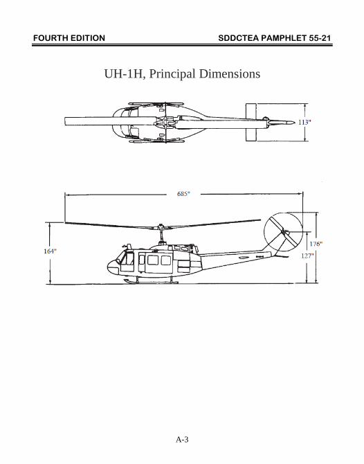
UH-1H, Principal Dimensions
FOURTH EDITION SDDCTEA PAMPHLET 55-21
A-4
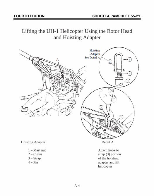
Lifting the UH-1 Helicopter Using the Rotor Head and Hoisting Adapter
Hoisting Adapter Detail A 1 – Mast nut Attach hook to 2 – Clevis strap (3) portion 3 – Strap of the hoisting 4 – Pin adapter and lift helicopter
FOURTH EDITION SDDCTEA PAMPHLET 55-21
A-5
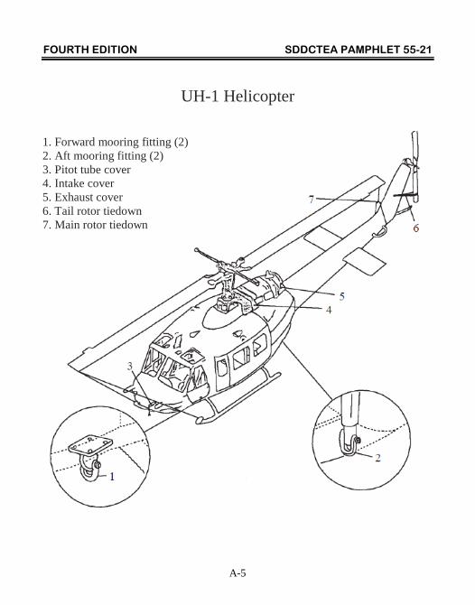
UH-1 Helicopter
1. Forward mooring fitting (2) 2. Aft mooring fitting (2) 3. Pitot tube cover 4. Intake cover 5. Exhaust cover 6. Tail rotor tiedown 7. Main rotor tiedown
FOURTH EDITION SDDCTEA PAMPHLET 55-21
A-6
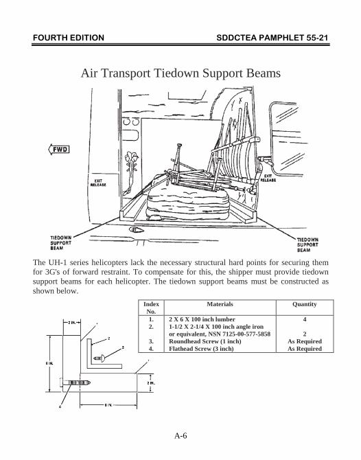
Air Transport Tiedown Support Beams
The UH-1 series helicopters lack the necessary structural hard points for securing them for 3G's of forward restraint. To compensate for this, the shipper must provide tiedown support beams for each helicopter. The tiedown support beams must be constructed as shown below.
Index No.
Materials Quantity
1. 2.
3. 4.
2 X 6 X 100 inch lumber 1-1/2 X 2-1/4 X 100 inch angle iron or equivalent, NSN 7125-00-577-5858 Roundhead Screw (1 inch) Flathead Screw (3 inch)
4 2
As Required As Required
FOURTH EDITION SDDCTEA PAMPHLET 55-21
A-7
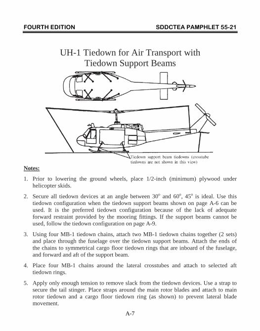
UH-1 Tiedown for Air Transport with Tiedown Support Beams
Notes:
1. Prior to lowering the ground wheels, place 1/2-inch (minimum) plywood under helicopter skids.
2. Secure all tiedown devices at an angle between 30o and 60o, 45o is ideal. Use this tiedown configuration when the tiedown support beams shown on page A-6 can be used. It is the preferred tiedown configuration because of the lack of adequate forward restraint provided by the mooring fittings. If the support beams cannot be used, follow the tiedown configuration on page A-9.
3. Using four MB-1 tiedown chains, attach two MB-1 tiedown chains together (2 sets) and place through the fuselage over the tiedown support beams. Attach the ends of the chains to symmetrical cargo floor tiedown rings that are inboard of the fuselage, and forward and aft of the support beam.
4. Place four MB-1 chains around the lateral crosstubes and attach to selected aft tiedown rings.
5. Apply only enough tension to remove slack from the tiedown devices. Use a strap to secure the tail stinger. Place straps around the main rotor blades and attach to main rotor tiedown and a cargo floor tiedown ring (as shown) to prevent lateral blade movement.
FOURTH EDITION SDDCTEA PAMPHLET 55-21
A-8
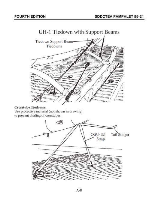
UH-1 Tiedown with Support Beams
Crosstube Tiedowns Use protective material (not shown in drawing) to prevent chafing of crosstubes
FOURTH EDITION SDDCTEA PAMPHLET 55-21
A-9
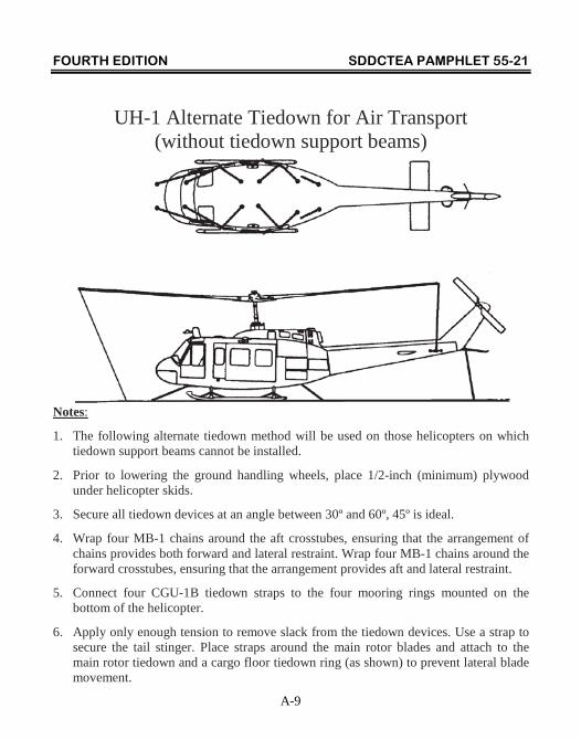
UH-1 Alternate Tiedown for Air Transport (without tiedown support beams)
Notes:
1. The following alternate tiedown method will be used on those helicopters on which tiedown support beams cannot be installed.
2. Prior to lowering the ground handling wheels, place 1/2-inch (minimum) plywood under helicopter skids.
3. Secure all tiedown devices at an angle between 30º and 60º, 45º is ideal.
4. Wrap four MB-1 chains around the aft crosstubes, ensuring that the arrangement of chains provides both forward and lateral restraint. Wrap four MB-1 chains around the forward crosstubes, ensuring that the arrangement provides aft and lateral restraint.
5. Connect four CGU-1B tiedown straps to the four mooring rings mounted on the bottom of the helicopter.
6. Apply only enough tension to remove slack from the tiedown devices. Use a strap to secure the tail stinger. Place straps around the main rotor blades and attach to the main rotor tiedown and a cargo floor tiedown ring (as shown) to prevent lateral blade movement.
FOURTH EDITION SDDCTEA PAMPHLET 55-21
A-10
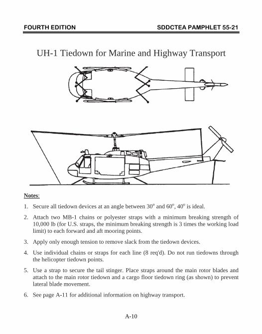
UH-1 Tiedown for Marine and Highway Transport
Notes:
1. Secure all tiedown devices at an angle between 30o and 60o, 40o is ideal.
2. Attach two MB-1 chains or polyester straps with a minimum breaking strength of 10,000 lb (for U.S. straps, the minimum breaking strength is 3 times the working load limit) to each forward and aft mooring points.
3. Apply only enough tension to remove slack from the tiedown devices.
4. Use individual chains or straps for each line (8 req'd). Do not run tiedowns through the helicopter tiedown points.
5. Use a strap to secure the tail stinger. Place straps around the main rotor blades and attach to the main rotor tiedown and a cargo floor tiedown ring (as shown) to prevent lateral blade movement.
6. See page A-11 for additional information on highway transport.
FOURTH EDITION SDDCTEA PAMPHLET 55-21
A-11
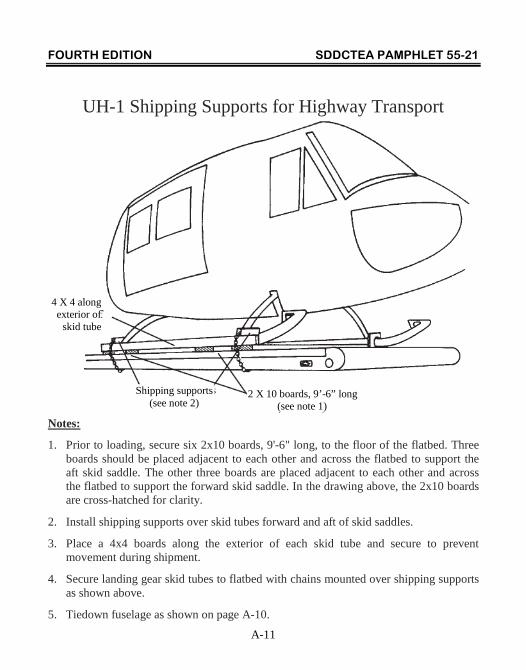
UH-1 Shipping Supports for Highway Transport
Notes:
1. Prior to loading, secure six 2x10 boards, 9'-6" long, to the floor of the flatbed. Three boards should be placed adjacent to each other and across the flatbed to support the aft skid saddle. The other three boards are placed adjacent to each other and across the flatbed to support the forward skid saddle. In the drawing above, the 2x10 boards are cross-hatched for clarity.
2. Install shipping supports over skid tubes forward and aft of skid saddles.
3. Place a 4x4 boards along the exterior of each skid tube and secure to prevent movement during shipment.
4. Secure landing gear skid tubes to flatbed with chains mounted over shipping supports as shown above.
5. Tiedown fuselage as shown on page A-10.
2 X 10 boards, 9’-6” long (see note 1)
Shipping supports (see note 2)
4 X 4 along exterior of
skid tube
FOURTH EDITION SDDCTEA PAMPHLET 55-21
B-1
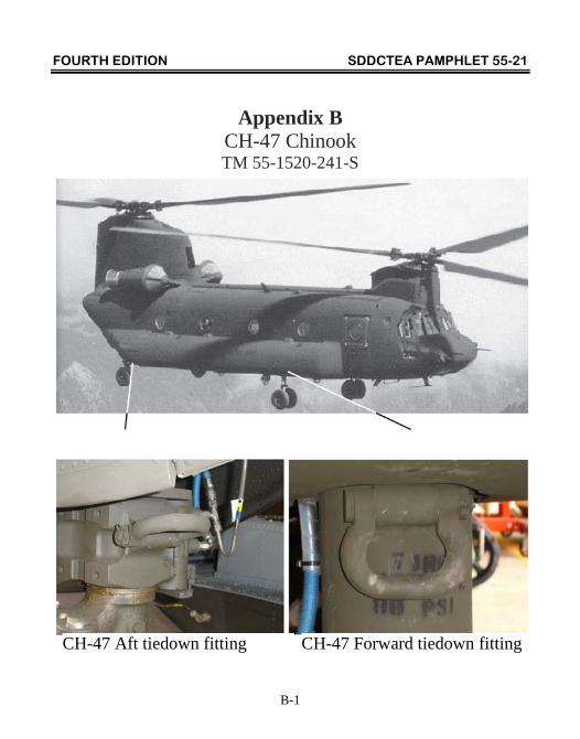
Appendix B CH-47 Chinook TM 55-1520-241-S
CH-47 Aft tiedown fitting CH-47 Forward tiedown fitting
FOURTH EDITION SDDCTEA PAMPHLET 55-21
B-2
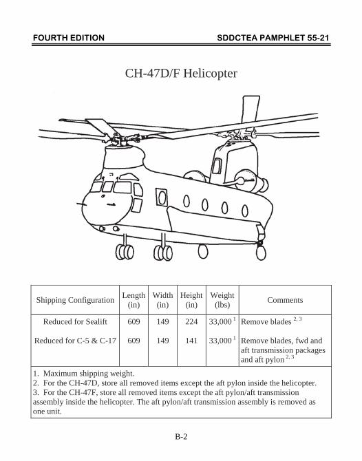
CH-47D/F Helicopter
Shipping Configuration Length
(in) Width
(in) Height
(in) Weight
(lbs) Comments
Reduced for Sealift
Reduced for C-5 & C-17
609
609
149
149
224
141
33,000 1
33,000 1
Remove blades 2, 3
Remove blades, fwd and aft transmission packages and aft pylon 2, 3
1. Maximum shipping weight. 2. For the CH-47D, store all removed items except the aft pylon inside the helicopter. 3. For the CH-47F, store all removed items except the aft pylon/aft transmission assembly inside the helicopter. The aft pylon/aft transmission assembly is removed as one unit.
FOURTH EDITION SDDCTEA PAMPHLET 55-21
B-3
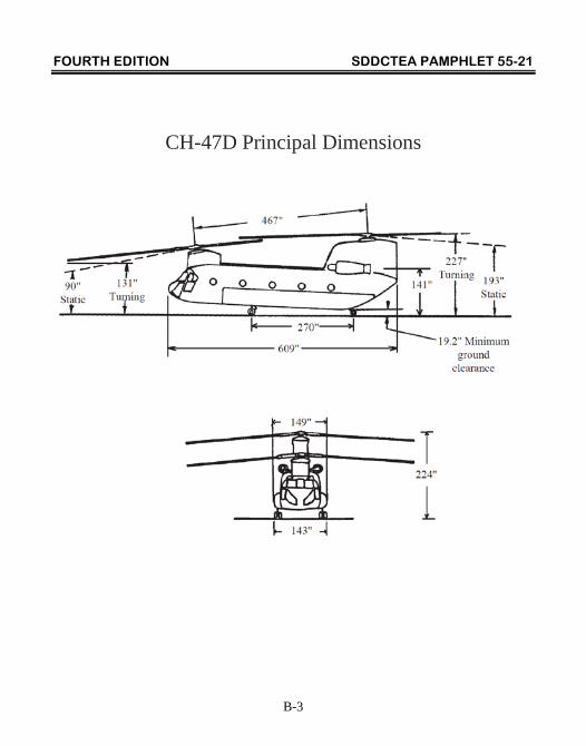
CH-47D Principal Dimensions
FOURTH EDITION SDDCTEA PAMPHLET 55-21
B-4
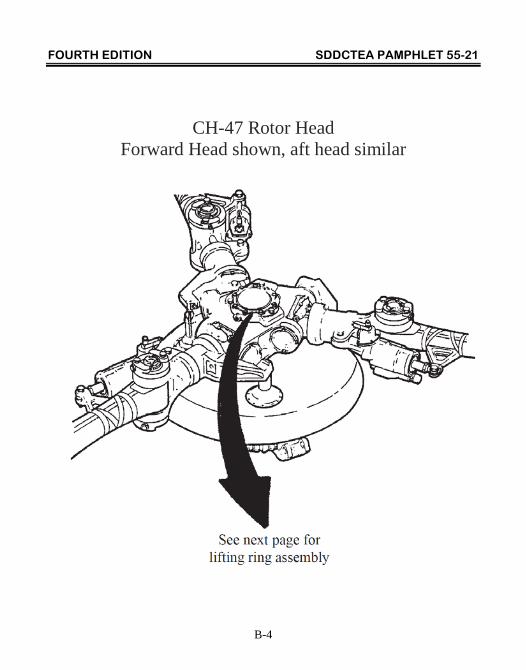
CH-47 Rotor Head
Forward Head shown, aft head similar
FOURTH EDITION SDDCTEA PAMPHLET 55-21
B-5
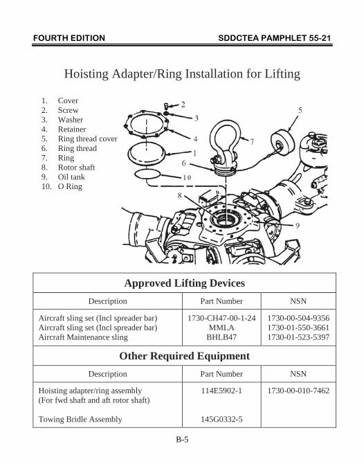
Hoisting Adapter/Ring Installation for Lifting
1. Cover 2. Screw 3. Washer 4. Retainer 5. Ring thread cover 6. Ring thread 7. Ring 8. Rotor shaft 9. Oil tank 10. O Ring
Approved Lifting Devices
Description Part Number NSN
Aircraft sling set (Incl spreader bar) Aircraft sling set (Incl spreader bar) Aircraft Maintenance sling
1730-CH47-00-1-24 MMLA
BHLB47
1730-00-504-9356 1730-01-550-3661 1730-01-523-5397
Other Required Equipment Description Part Number NSN
Hoisting adapter/ring assembly (For fwd shaft and aft rotor shaft) Towing Bridle Assembly
114E5902-1
145G0332-5
1730-00-010-7462
FOURTH EDITION SDDCTEA PAMPHLET 55-21
B-6
CH-47 Lifting Guidance (using one of the approved Aircraft Sling Sets listing on page B-5)
Notes:
1. Inspect hoisting adapters for thread damage. Fully screw hoisting adapter into shaft; a minimum engagement of eight threads is required.
2. Attach hoisting slings to forward and aft rotor shafts with two hoisting adapters. If the aircraft sling set listed in the table on page B-5 is not available, use a spreader bar with a capacity of at least 33,000 lbs and 442 inches (36'-10") in length, and sling lengths as shown in the figure above.
Maximum Lifting Weight is 33,000 lbs

FOURTH EDITION SDDCTEA PAMPHLET 55-21
B-7
CH-47 Lifting Guidance (using the Aircraft Maintenance Sling, BHLB47)
The BHLB47 helicopter lifting assembly is used to adapt a standard 40-foot container spreader to lift CH-47 series helicopters aboard ships for deployment. Although, the BHLB47 assembly can handle helicopters up to 40,000 pounds, the maximum lifting weight for the CH-47 is 33,000 pounds. The lifting assembly works with cranes equipped with automatic adjustable container spreaders, and standard container spreaders.
Parts List for BHLB47 Lifting Assembly
Description Part Number Quantity
Shipping/Storage Box BHLB47-1 1
Operators Manual BHLB47-2 1
Lifting Spreader BHLB47-3 2
8’ x 15,000 lb. High-Performance Synthetic Sling BHLB47-4 4
7’ x 20,000 lb. High-Performance Synthetic Sling (for forward rotor head) BHLB47-5 1
4’ x 20,000 lb. High-Performance Synthetic Sling (for aft rotor head) BHLB47-6 1
1-3/8” Safety Shackle BHLB47-7 8
Tagline, 5/8” diameter, 3-part, nylon, 100 feet long BHLB47-8 4
FOURTH EDITION SDDCTEA PAMPHLET 55-21
B-8
CH-47 Lifting Guidance (using a BHLB47, Aircraft Maintenance Sling)
FOURTH EDITION SDDCTEA PAMPHLET 55-21
B-9
Setup and Installation for the BHLB47, Aircraft Maintenance Sling
Step #1 - If using an automatic, adjustable container spreader, measure the width between the legs of the gantry through which the helicopter must pass. If this width is less than 60 feet, use a standard container spreader to lift the helicopter. Attach tag lines, BHLB47-8, to both corners on one long side of the standard spreader.
Step #2 - If using an automatic, adjustable container spreader, set it to the standard 40-foot container position (ISO standard IA position). If using a manual lifter, ensure it is designed for a standard 40-foot container (ISO standard IA size). Lower the container spreader and mark the position of the twist-locks on the pavement.
Step #3 - Place the lifting spreaders, BHLB47-3, with the top sockets aligned with the marks on the pavement made in step #2 (see below). The pointer arrows marked on the lifting spreaders must be facing each other. Assemble shackles and slings to the lifting spreaders as shown on the drawing on page B- 10. Extend slings outward from ends of the container lifter as shown below.
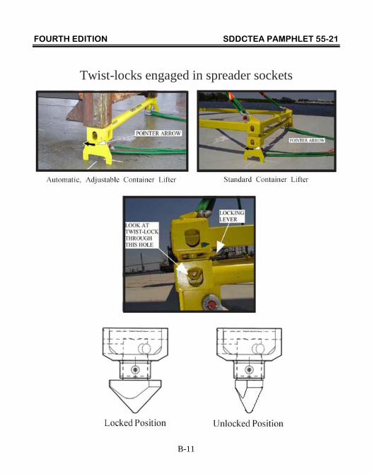
Step #4 - Lower the container spreader until the twist-locks engage the sockets on top of the lifting spreaders. Verify that the twist-locks have rotated into the locked position by looking through the openings of the spreader lock boxes. Sec photos on page B-11.
Step #5 - Slowly raise the container spreader and watch the slings as they hang vertically from the spreader. The slings should lie over the shackle pins or in the bow of the shackles without being twisted, folded, or overlapped.
Step #6 - Attach the 7-foot sling to the forward rotor hub and the 4-foot sling to the aft rotor hub. Lift the helicopter as shown on page B-12.
FOURTH EDITION SDDCTEA PAMPHLET 55-21
B-10
Shackle and High-Performance Synthetic Sling Setup
FOURTH EDITION SDDCTEA PAMPHLET 55-21
B-11
Twist-locks engaged in spreader sockets
FOURTH EDITION SDDCTEA PAMPHLET 55-21
B-12
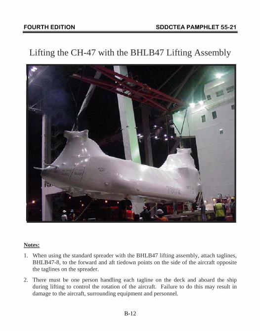
Lifting the CH-47 with the BHLB47 Lifting Assembly
Notes:
1. When using the standard spreader with the BHLB47 lifting assembly, attach taglines, BHLB47-8, to the forward and aft tiedown points on the side of the aircraft opposite the taglines on the spreader.
2. There must be one person handling each tagline on the deck and aboard the ship during lifting to control the rotation of the aircraft. Failure to do this may result in damage to the aircraft, surrounding equipment and personnel.
FOURTH EDITION SDDCTEA PAMPHLET 55-21
B-13
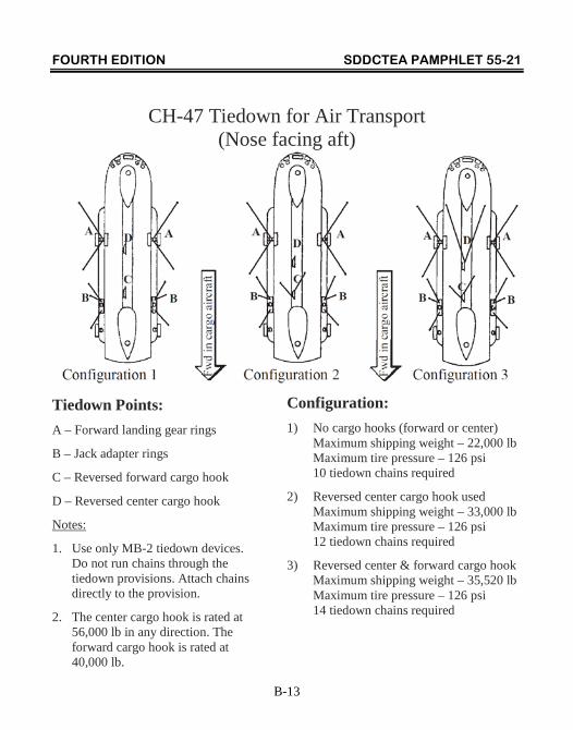
CH-47 Tiedown for Air Transport (Nose facing aft)
Tiedown Points: A – Forward landing gear rings
B – Jack adapter rings
C – Reversed forward cargo hook
D – Reversed center cargo hook
Notes:
1. Use only MB-2 tiedown devices. Do not run chains through the tiedown provisions. Attach chains directly to the provision.
2. The center cargo hook is rated at 56,000 lb in any direction. The forward cargo hook is rated at 40,000 lb.
Configuration: 1) No cargo hooks (forward or center) Maximum shipping weight – 22,000 lb Maximum tire pressure – 126 psi 10 tiedown chains required
2) Reversed center cargo hook used Maximum shipping weight – 33,000 lb Maximum tire pressure – 126 psi 12 tiedown chains required
3) Reversed center & forward cargo hook Maximum shipping weight – 35,520 lb Maximum tire pressure – 126 psi 14 tiedown chains required
FOURTH EDITION SDDCTEA PAMPHLET 55-21
B-14
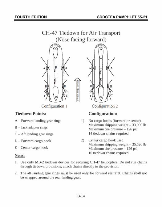
CH-47 Tiedown for Air Transport (Nose facing forward)
Tiedown Points: A – Forward landing gear rings
B – Jack adapter rings
C – Aft landing gear rings
D – Forward cargo hook
E – Center cargo hook
Configuration: 1) No cargo hooks (forward or center) Maximum shipping weight – 33,000 lb Maximum tire pressure – 126 psi 14 tiedown chains required
2) Center cargo hook used Maximum shipping weight – 35,520 lb Maximum tire pressure – 126 psi 16 tiedown chains required
Notes:
1. Use only MB-2 tiedown devices for securing CH-47 helicopters. Do not run chains through tiedown provisions; attach chains directly to the provision.
2. The aft landing gear rings must be used only for forward restraint. Chains shall not be wrapped around the rear landing gear.
FOURTH EDITION SDDCTEA PAMPHLET 55-21
B-15
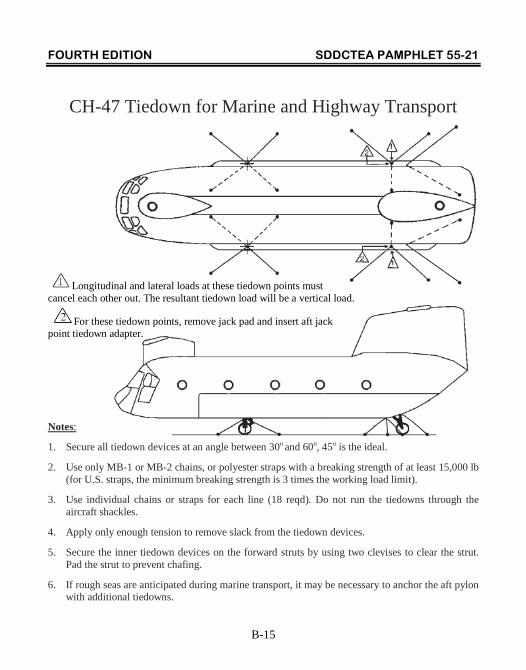
CH-47 Tiedown for Marine and Highway Transport
Longitudinal and lateral loads at these tiedown points must cancel each other out. The resultant tiedown load will be a vertical load.
For these tiedown points, remove jack pad and insert aft jack point tiedown adapter.
Notes:
1. Secure all tiedown devices at an angle between 30o and 60o, 45o is the ideal.
2. Use only MB-1 or MB-2 chains, or polyester straps with a breaking strength of at least 15,000 lb (for U.S. straps, the minimum breaking strength is 3 times the working load limit).
3. Use individual chains or straps for each line (18 reqd). Do not run the tiedowns through the aircraft shackles.
4. Apply only enough tension to remove slack from the tiedown devices.
5. Secure the inner tiedown devices on the forward struts by using two clevises to clear the strut. Pad the strut to prevent chafing.
6. If rough seas are anticipated during marine transport, it may be necessary to anchor the aft pylon with additional tiedowns.
FOURTH EDITION SDDCTEA PAMPHLET 55-21
C-1
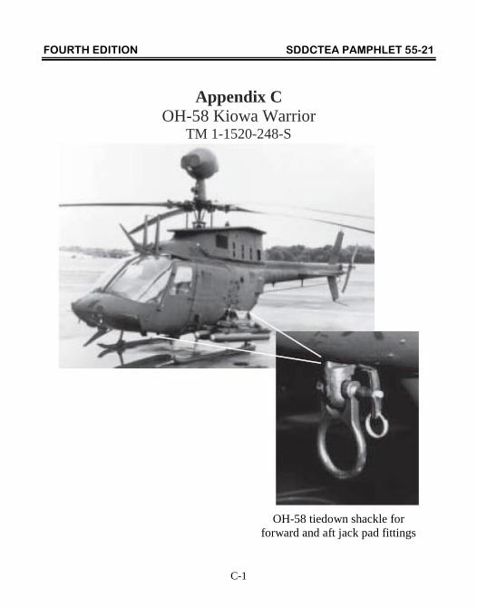
Appendix C OH-58 Kiowa Warrior
TM 1-1520-248-S
OH-58 tiedown shackle for forward and aft jack pad fittings
FOURTH EDITION SDDCTEA PAMPHLET 55-21
C-2
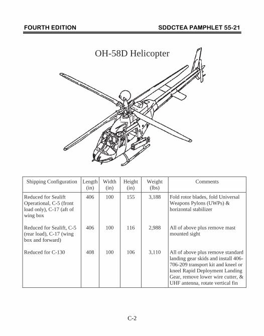
OH-58D Helicopter
Shipping Configuration Length (in)
Width (in)
Height (in)
Weight (lbs)
Comments
Reduced for Sealift Operational, C-5 (front load only), C-17 (aft of wing box Reduced for Sealift, C-5 (rear load), C-17 (wing box and forward) Reduced for C-130
406
406
408
100
100
100
155
116
106
3,188
2,988
3,110
Fold rotor blades, fold Universal Weapons Pylons (UWPs) & horizontal stabilizer All of above plus remove mast mounted sight All of above plus remove standard landing gear skids and install 406-706-209 transport kit and kneel or kneel Rapid Deployment Landing Gear, remove lower wire cutter, & UHF antenna, rotate vertical fin
FOURTH EDITION SDDCTEA PAMPHLET 55-21
C-3
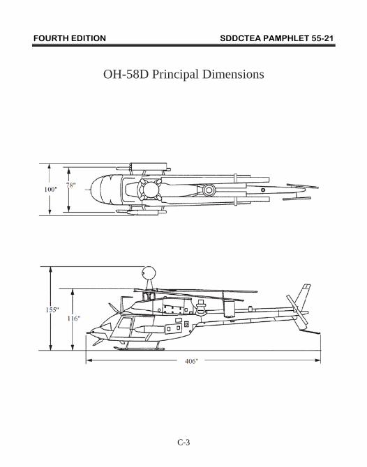
OH-58D Principal Dimensions
FOURTH EDITION SDDCTEA PAMPHLET 55-21
C-4
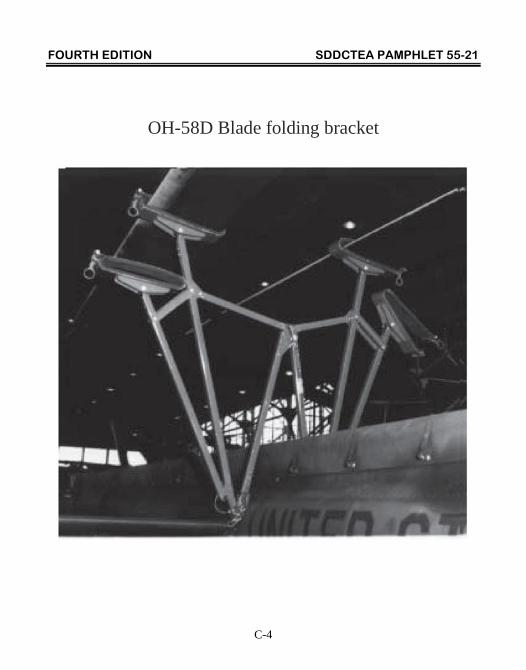
OH-58D Blade folding bracket
FOURTH EDITION SDDCTEA PAMPHLET 55-21
C-5
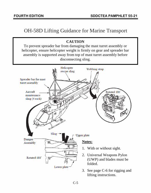
OH-58D Lifting Guidance for Marine Transport
CAUTION To prevent spreader bar from damaging the mast turret assembly or
helicopter, ensure helicopter weight is firmly on gear and spreader bar assembly is supported away from top of mast turret assembly before
disconnecting sling.
Notes:
1. With or without sight.
2. Universal Weapons Pylon (UWP) and blades must be folded.
3. See page C-6 for rigging and lifting instructions.
FOURTH EDITION SDDCTEA PAMPHLET 55-21
C-6
OH-58D Lifting Guidance for Marine Transport (cont) Rigging and Lifting Instructions:
1. Attach the ends of the four upper slings attached to the spreader bar.
2. Attach one end of the helicopter rescue sling to the spreader bar.
3. Secure retaining pin in clevis with bolt and nut.
4. Place clevis in hook of dockside or shipboard crane.
5. Position spreader bar centered directly over mast mounted sight.
6. Attach one end of aircraft maintenance sling to clevis on spreader bar. Pass other end of sling down through upper yoke of main rotor hub and back up to the same clevis on spreader bar and secure clevis.
7. Repeat #6 for the three remaining spreader bar legs.
8. Pass webbing strap through forward mount of vertical stabilizer and through free end of the helicopter rescue sling attached to clevis.
9. Secure ends of webbing strap together and remove slack.
10. Remove ground handling wheels and tow bar.
11. Lift helicopter onto the ship and down through the hold to lower deck.
12. Stabilize helicopter with tag lines as it is being lifted and lowered to prevent it from striking the ship structure.
FOURTH EDITION SDDCTEA PAMPHLET 55-21
C-7
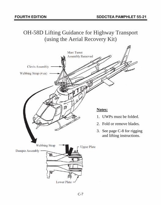
OH-58D Lifting Guidance for Highway Transport (using the Aerial Recovery Kit)
Notes:
1. UWPs must be folded.
2. Fold or remove blades.
3. See page C-8 for rigging and lifting instructions.
FOURTH EDITION SDDCTEA PAMPHLET 55-21
C-8
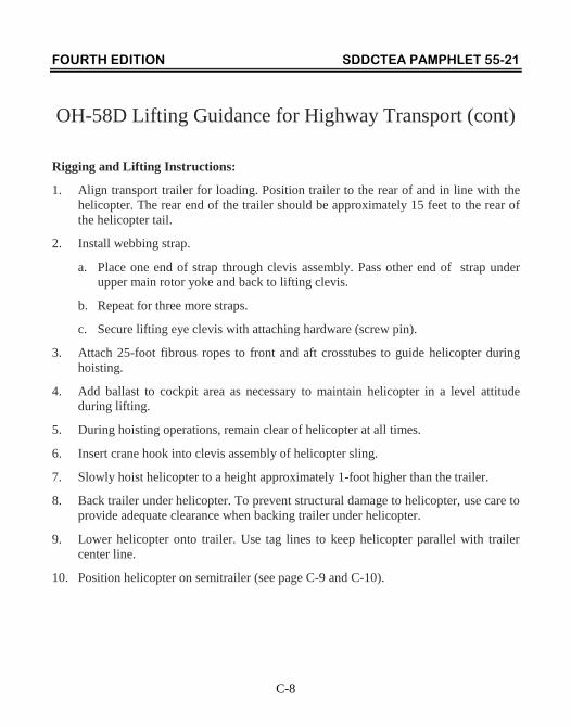
OH-58D Lifting Guidance for Highway Transport (cont)
Rigging and Lifting Instructions:
1. Align transport trailer for loading. Position trailer to the rear of and in line with the helicopter. The rear end of the trailer should be approximately 15 feet to the rear of the helicopter tail.
2. Install webbing strap.
a. Place one end of strap through clevis assembly. Pass other end of strap under upper main rotor yoke and back to lifting clevis.
b. Repeat for three more straps.
c. Secure lifting eye clevis with attaching hardware (screw pin).
3. Attach 25-foot fibrous ropes to front and aft crosstubes to guide helicopter during hoisting.
4. Add ballast to cockpit area as necessary to maintain helicopter in a level attitude during lifting.
5. During hoisting operations, remain clear of helicopter at all times.
6. Insert crane hook into clevis assembly of helicopter sling.
7. Slowly hoist helicopter to a height approximately 1-foot higher than the trailer.
8. Back trailer under helicopter. To prevent structural damage to helicopter, use care to provide adequate clearance when backing trailer under helicopter.
9. Lower helicopter onto trailer. Use tag lines to keep helicopter parallel with trailer center line.
10. Position helicopter on semitrailer (see page C-9 and C-10).

FOURTH EDITION SDDCTEA PAMPHLET 55-21
C-9
Loading Diagram for M270A1 Military Tactical Transport Semitrailer
NOTE: The UWPs will extend beyond the width of the trailer by 1-1/2 inches on each side.
NOTE: Secure all blades in blade rack.
FOURTH EDITION SDDCTEA PAMPHLET 55-21
C-10
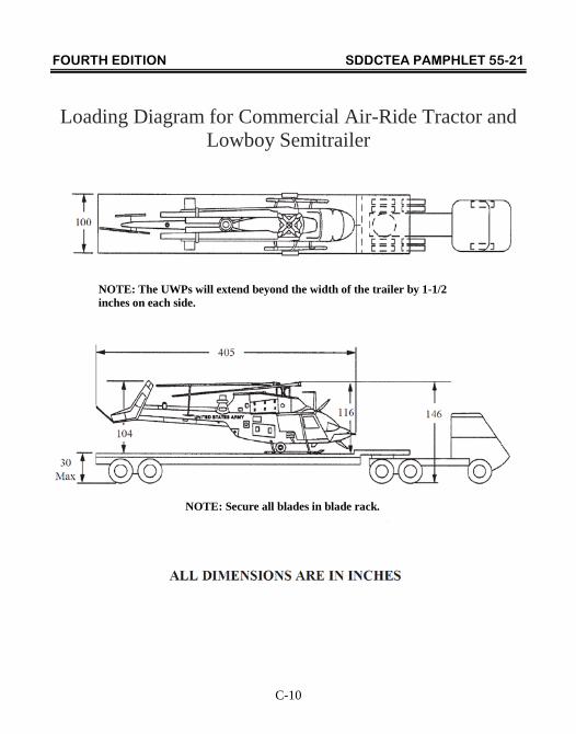
Loading Diagram for Commercial Air-Ride Tractor and Lowboy Semitrailer
NOTE: The UWPs will extend beyond the width of the trailer by 1-1/2 inches on each side.
NOTE: Secure all blades in blade rack.
FOURTH EDITION SDDCTEA PAMPHLET 55-21
C-11
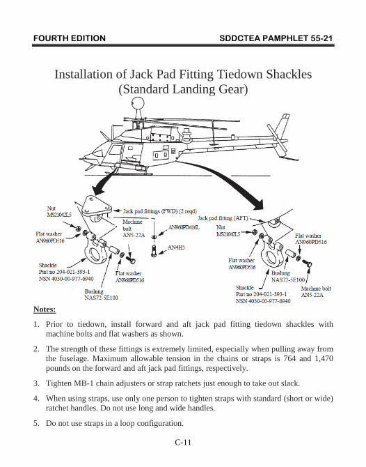
Installation of Jack Pad Fitting Tiedown Shackles (Standard Landing Gear)
Notes:
1. Prior to tiedown, install forward and aft jack pad fitting tiedown shackles with machine bolts and flat washers as shown.
2. The strength of these fittings is extremely limited, especially when pulling away from the fuselage. Maximum allowable tension in the chains or straps is 764 and 1,470 pounds on the forward and aft jack pad fittings, respectively.
3. Tighten MB-1 chain adjusters or strap ratchets just enough to take out slack.
4. When using straps, use only one person to tighten straps with standard (short or wide) ratchet handles. Do not use long and wide handles.
5. Do not use straps in a loop configuration.
FOURTH EDITION SDDCTEA PAMPHLET 55-21
C-12
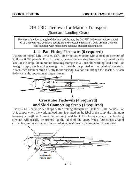
OH-58D Tiedown for Marine Transport (Standard Landing Gear)
Jack Pad Fitting Tiedowns (6 required) Use six individual MB-1 chains, CGU-1B or polyester straps with a breaking strength of 5,000 or 6,000 pounds. For U.S. straps, where the working load limit is printed on the label of the strap, the minimum breaking strength is 3 times the working load limit. For foreign straps, the breaking strength will usually be printed on the label of the strap. Attach each chain or strap directly to the shackle. Do not fun through the shackle. Attach tiedowns at the approximate angle shown.
Crosstube Tiedowns (4 required) and Skid Connecting Strap (1 required)
Use CGU-1B or polyester straps with breaking strength of 5,000 or 6,000 pounds. For U.S. straps, where the working load limit is printed on the label of the strap, the minimum breaking strength is 3 times the working load limit. For foreign straps, the breaking strength will usually be printed on the label of the strap. Wrap four straps around crosstubes, and one strap across legs of skin, as shown in photographs on next page.
Because of the low strength of the jack pad fittings, the OH-58D helicopter requires a total of 11 tiedowns (use both jack pad fitting and crosstube tiedowns). Only use this tiedown
configuration with helicopters that have standard landing gear.
FOURTH EDITION SDDCTEA PAMPHLET 55-21
C-13
OH-58D Crosstube Tiedowns and Skid Connecting Strap for Marine Transport (Standard Landing Gear)
Front Crosstube: Wrap straps (CGU-1B or polyester straps with a breaking strength of 5,000 or 6,000 pounds) around crosstube inside of where the fuselage mounts to the skids.
Aft Crosstube: Wrap strap (CGU-1B or polyester strap with a breaking strength of 5,000 or 6,000 pounds) around crosstube as close to the outboard side or the fuselage mounts as possible. In addition to the aft crosstube straps, use a strap to connect the skid tubes just forward of the crosstube saddles and jack pad fittings.
FOURTH EDITION SDDCTEA PAMPHLET 55-21
C-14
OH-58D Tiedown for Air and Highway Transport (Standard Landing Gear, No Transport Kit)
Note:
Use only MB-1 chains for air transport. MB-1 chains, CGU-1B or polyester straps with a breaking strength of 5,000 or 6,000 pounds can be used for highway transport. For U.S. straps, where the working load limit is printed on the label of the strap, the minimum breaking strength is 3 times the working load limit. For foreign straps, the breaking strength will usually be printed on the label of the strap. Attach each chain or strap directly to the shackle on the jack pad tiedowns. Do not run through the shackle. Attach tiedowns at the approximate angle shown. Attach skid connecting strap as shown on page C-13.
FOURTH EDITION SDDCTEA PAMPHLET 55-21
C-15
OH-58D Standard Landing Gear, Transportability Kit
Notes:
1. Numbers 1 through 4 are tiedown points. The maximum vertical load on the tiedown points is 4,127 lb. One strap or chain is required at each of these points. The chain or strap must pass through the tiedown point. No attachment is permitted. The chain or strap must be secured at two points, one forward of tiedown point and one aft of it. See page C-16.
2. Numbers 5 through 10 are tiedown shackles. The maximum forward, aft and lateral allowable load on the tiedown shackles is 4,500 lb. Attach chains or straps to tiedown shackles as shown on page C-16.
3. The tiedown loads are based on a maximum gross weight of 3,814 lb.
FOURTH EDITION SDDCTEA PAMPHLET 55-21
C-16
OH-58D Tiedown for Air, Marine, and Highway Transport
(Standard Landing Gear, Transportability Kit Installed)
Note:
Only tiedowns for points 1-4 are shown in this view.
FOURTH EDITION SDDCTEA PAMPHLET 55-21
C-17
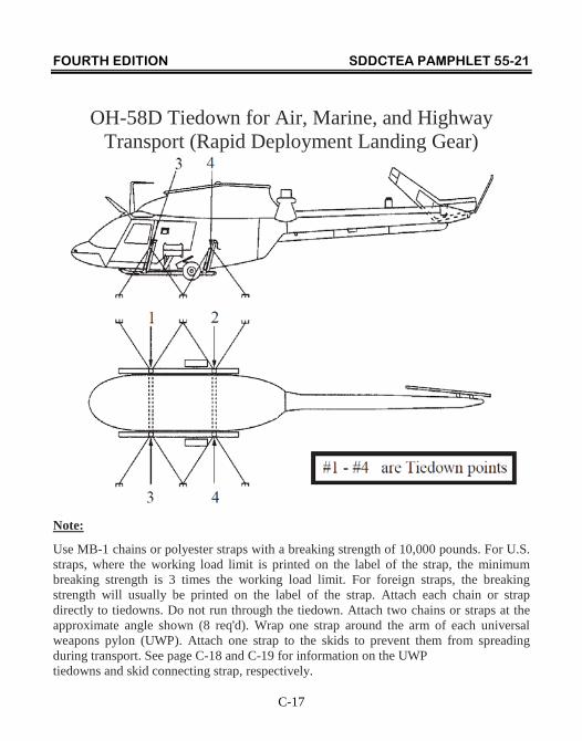
OH-58D Tiedown for Air, Marine, and Highway Transport (Rapid Deployment Landing Gear)
Note:
Use MB-1 chains or polyester straps with a breaking strength of 10,000 pounds. For U.S. straps, where the working load limit is printed on the label of the strap, the minimum breaking strength is 3 times the working load limit. For foreign straps, the breaking strength will usually be printed on the label of the strap. Attach each chain or strap directly to tiedowns. Do not run through the tiedown. Attach two chains or straps at the approximate angle shown (8 req'd). Wrap one strap around the arm of each universal weapons pylon (UWP). Attach one strap to the skids to prevent them from spreading during transport. See page C-18 and C-19 for information on the UWP tiedowns and skid connecting strap, respectively.
FOURTH EDITION SDDCTEA PAMPHLET 55-21
C-18
OH-58D Tiedown for Air, Marine, and Highway Transport (Rapid Deployment Landing Gear)
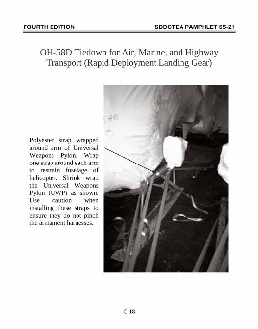
Polyester strap wrapped around arm of Universal Weapons Pylon. Wrap one strap around each arm to restrain fuselage of helicopter. Shrink wrap the Universal Weapons Pylon (UWP) as shown. Use caution when installing these straps to ensure they do not pinch the armament harnesses.
FOURTH EDITION SDDCTEA PAMPHLET 55-21
C-19
OH-58D Skid Connecting Strap for Air, Marine, and Highway Transport (Rapid Deployment Landing Gear)
Note:
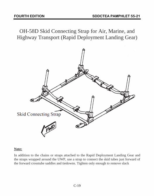
In addition to the chains or straps attached to the Rapid Deployment Landing Gear and the straps wrapped around the UWP, use a strap to connect the skid tubes just forward of the forward crosstube saddles and tiedowns. Tighten only enough to remove slack
FOURTH EDITION SDDCTEA PAMPHLET 55-21
D-1
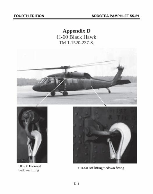
Appendix D H-60 Black Hawk TM 1-1520-237-S.
UH-60 Forward tiedown fitting UH-60 Aft lifting/tiedown fitting
FOURTH EDITION SDDCTEA PAMPHLET 55-21
D-2
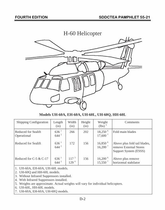
H-60 Helicopter
Models UH-60A, EH-60A, UH-60L, UH-60Q, HH-60L
Shipping Configuration Length (in)
Width (in)
Height (in)
Weight (lbs) 5
Comments
Reduced for Sealift Operational Reduced for Sealift Reduced for C-5 & C-17
636 1 644 2
636 1 644 2
636 1 644 2
266
172
117 3
129 4
202
156
156
18,250 6 17,600 7
16,850 6 16,200 7
16,200 6 15,550 7
Fold main blades Above plus fold tail blades, remove External Stores Support System (ESSS) Above plus remove horizontal stabilator
1. UH-60A, EH-60A, UH-60L models. 2. UH-60Q and HH-60L models. 3. Without Infrared Suppressors installed. 4. With Infrared Suppressors installed. 5. Weights are approximate. Actual weights will vary for individual helicopters. 6. UH-60L, HH-60L models. 7. UH-60A, EH-60A, UH-60Q models.
FOURTH EDITION SDDCTEA PAMPHLET 55-21
D-3
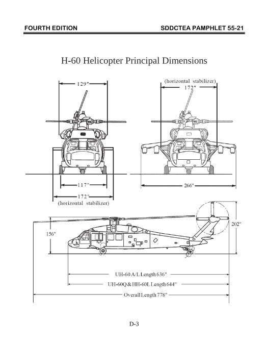
H-60 Helicopter Principal Dimensions
FOURTH EDITION SDDCTEA PAMPHLET 55-21
D-4
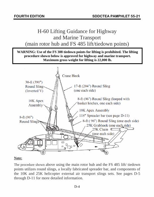
H-60 Lifting Guidance for Highway and Marine Transport
(main rotor hub and FS 485 lift/tiedown points)
Note:
The procedure shown above using the main rotor hub and the FS 485 lift/ tiedown points utilizes round slings, a locally fabricated spreader bar, and components of the 10K and 25K helicopter external air transport slings sets. See pages D-5 through D-11 for more detailed information.
WARNING: Use of the FS 308 tiedown points for lifting is prohibited. The lifting procedure shown below is approved for highway and marine transport.
Maximum gross weight for lifting is 22,000 lb.
FOURTH EDITION SDDCTEA PAMPHLET 55-21
D-5
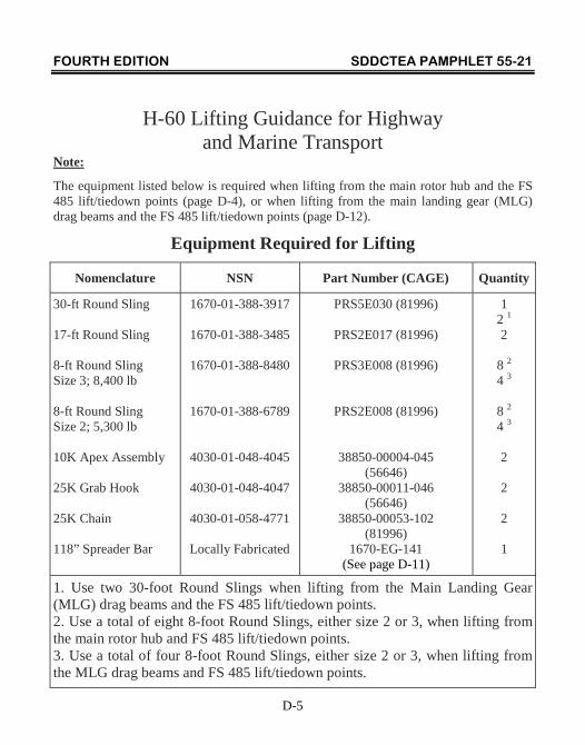
H-60 Lifting Guidance for Highway and Marine Transport
Note:
The equipment listed below is required when lifting from the main rotor hub and the FS 485 lift/tiedown points (page D-4), or when lifting from the main landing gear (MLG) drag beams and the FS 485 lift/tiedown points (page D-12).
Equipment Required for Lifting
Nomenclature NSN Part Number (CAGE) Quantity
30-ft Round Sling 17-ft Round Sling 8-ft Round Sling Size 3; 8,400 lb 8-ft Round Sling Size 2; 5,300 lb 10K Apex Assembly 25K Grab Hook 25K Chain 118” Spreader Bar
1670-01-388-3917
1670-01-388-3485
1670-01-388-8480
1670-01-388-6789
4030-01-048-4045
4030-01-048-4047
4030-01-058-4771
Locally Fabricated
PRS5E030 (81996)
PRS2E017 (81996)
PRS3E008 (81996)
PRS2E008 (81996)
38850-00004-045 (56646)
38850-00011-046 (56646)
38850-00053-102 (81996)
1670-EG-141 (See page D-11)
1 2 1
2
8 2 4 3
8 2 4 3
2
2
2
1
1. Use two 30-foot Round Slings when lifting from the Main Landing Gear (MLG) drag beams and the FS 485 lift/tiedown points. 2. Use a total of eight 8-foot Round Slings, either size 2 or 3, when lifting from the main rotor hub and FS 485 lift/tiedown points. 3. Use a total of four 8-foot Round Slings, either size 2 or 3, when lifting from the MLG drag beams and FS 485 lift/tiedown points.
FOURTH EDITION SDDCTEA PAMPHLET 55-21
D-6
H-60 Lifting Guidance for Highway and Marine Transport
Rigging and Lifting Instructions (main rotor hub and FS 485 lift/tiedown points): 1. Position wear pads next to eye on one end of each of four 8-foot round slings.
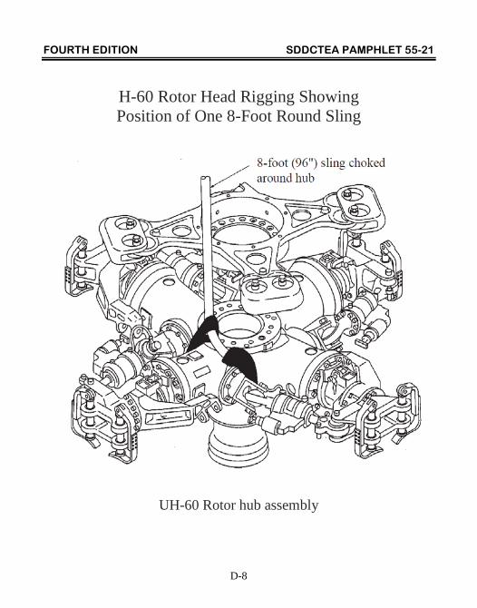
2. Loop eye end of 8-foot round sling around one arm of main rotor hub, routing sling between damper bracket and mast. Pass other end of sling through eye over hub arm (see page D-8). Position the wear pad under hub arm and over bolt circle on damper bracket and choke sling snug on hub arm.
3. Repeat #2 for the three remaining 8-foot round slings and hub arms.
4. Separate sling legs choked around front two arms of hub from two slings choked around rear two arms to assist in making the required connections to the eye hook.
5. Center wear pad mid-way between two ends of the 30-foot round slings and form into a two-leg inverted "V" sling (see page D-9).
6. Attach a 10-ton eye hook or larger to each end of the 30-foot round sling using 10K assemblies (see page D-9).
7. For aft portion of lifting sling, assemble two 8-foot round slings to two 25K grab hooks and chains from the 25K cargo sling (see page D-10).
8. Form two 21-foot lifting lines by attaching 8-foot round slings in basket hitches to the end of a 17-foot round sling. Center 8-foot round sling wear pads in eyes of 17-foot round sling (see page D-10).
9. Connect one 21-foot upper sling line to each shackle on 118" spreader bar sling with two ends of basket slings in bow of shackles (see page D-10).
10. Connect one 8-foot round sling (with grab-hook and chain attached) to pins at each end of spreader bar (see page D-10).
11. To attach assembly to crane hook, connect free ends of two 17-foot round slings to crane hook.
12. Center wear pad on 30-foot round sling and place wear pad over crane hook.
FOURTH EDITION SDDCTEA PAMPHLET 55-21
D-7
H-60 Lifting Guidance for Highway and Marine Transport (cont)
13. To attach lifting sling to helicopter, route one chain through aft lifting and tiedown ring (FS 485) and secure link number 30 in grab hook. Repeat procedure for other side of helicopter.
14. Attach 8-foot round slings attached to forward two arms of main rotor hub to eye hook in one end of 30-foot round sling. Attach two 8-foot round slings attached to aft two arms of main rotor hub to eye hook in other end of 30-foot round sling. To ensure equal loading of the hub, it is essential to attach one end of the 30-foot round sling to the forward arms of the main rotor hub, and the other end to the aft arms of the main rotor hub.
15. Attach two 50-foot-long tag lines (rope) to tail landing gear and stabilize tag lines during lifting operations.
16. Slowly raise hook to remove slack from sling. Adjust boom as necessary to center hook at apex of sling.
17. Slowly raise helicopter, checking attitude of helicopter as it is lifted. If main landing gear wheels are not off the ground by at least 1- foot before tailwheel clears the ground, lower helicopter to ground and adjust chain count in grab hook. Mark chain link to grab hook locations with tape for re-rig of sling at unloading.
FOURTH EDITION SDDCTEA PAMPHLET 55-21
D-8
H-60 Rotor Head Rigging Showing Position of One 8-Foot Round Sling
UH-60 Rotor hub assembly
FOURTH EDITION SDDCTEA PAMPHLET 55-21
D-9
Rotor Hub Sling Assembly
FOURTH EDITION SDDCTEA PAMPHLET 55-21
D-10
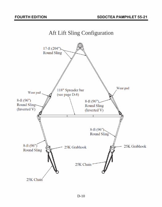
Aft Lift Sling Configuration
FOURTH EDITION SDDCTEA PAMPHLET 55-21
D-11
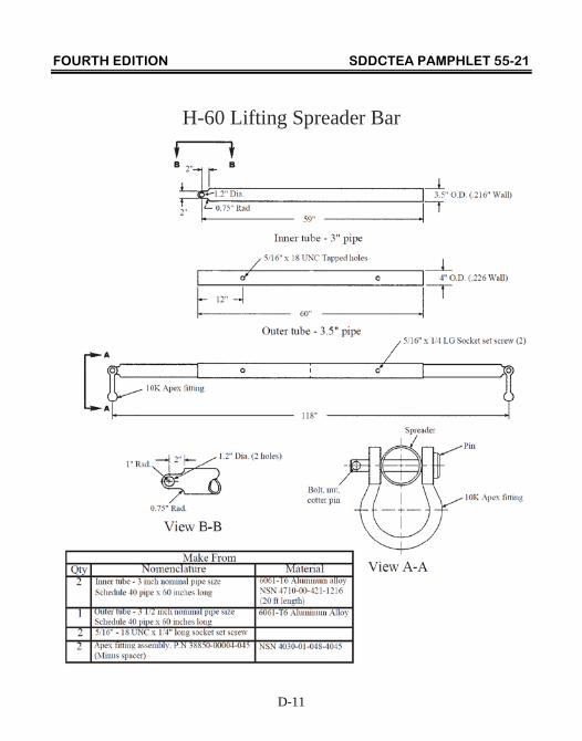
H-60 Lifting Spreader Bar
FOURTH EDITION SDDCTEA PAMPHLET 55-21
D-12
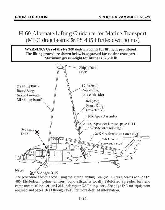
H-60 Alternate Lifting Guidance for Marine Transport (MLG drag beams & FS 485 lift/tiedown points)
Note:
The procedure shown above using the Main Landing Gear (MLG) drag beams and the FS 485 lift/tiedown points utilizes round slings, a locally fabricated spreader bar, and components of the 10K and 25K helicopter EAT slings sets. See page D-5 for equipment required and pages D-13 through D-15 for more detailed information.
WARNING: Use of the FS 308 tiedown points for lifting is prohibited. The lifting procedure shown below is approved for marine transport.
Maximum gross weight for lifting is 17,250 lb
FOURTH EDITION SDDCTEA PAMPHLET 55-21
D-13
H-60 Alternate Lifting Guidance for Marine Transport
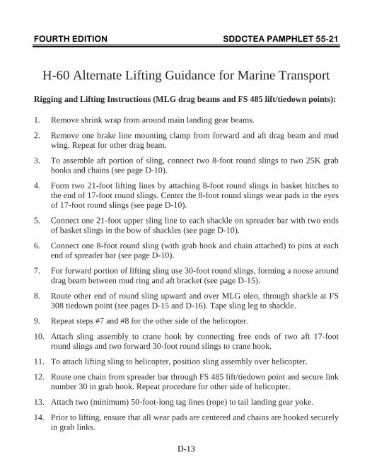
Rigging and Lifting Instructions (MLG drag beams and FS 485 lift/tiedown points):
1. Remove shrink wrap from around main landing gear beams.
2. Remove one brake line mounting clamp from forward and aft drag beam and mud wing. Repeat for other drag beam.
3. To assemble aft portion of sling, connect two 8-foot round slings to two 25K grab hooks and chains (see page D-10).
4. Form two 21-foot lifting lines by attaching 8-foot round slings in basket hitches to the end of 17-foot round slings. Center the 8-foot round slings wear pads in the eyes of 17-foot round slings (see page D-10).
5. Connect one 21-foot upper sling line to each shackle on spreader bar with two ends of basket slings in the bow of shackles (see page D-10).
6. Connect one 8-foot round sling (with grab hook and chain attached) to pins at each end of spreader bar (see page D-10).
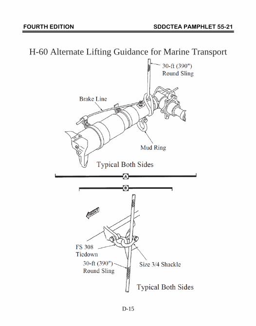
7. For forward portion of lifting sling use 30-foot round slings, forming a noose around drag beam between mud ring and aft bracket (see page D-15).
8. Route other end of round sling upward and over MLG oleo, through shackle at FS 308 tiedown point (see pages D-15 and D-16). Tape sling leg to shackle.
9. Repeat steps #7 and #8 for the other side of the helicopter.
10. Attach sling assembly to crane hook by connecting free ends of two aft 17-foot round slings and two forward 30-foot round slings to crane hook.
11. To attach lifting sling to helicopter, position sling assembly over helicopter.
12. Route one chain from spreader bar through FS 485 lift/tiedown point and secure link number 30 in grab hook. Repeat procedure for other side of helicopter.
13. Attach two (minimum) 50-foot-long tag lines (rope) to tail landing gear yoke.
14. Prior to lifting, ensure that all wear pads are centered and chains are hooked securely in grab links.
FOURTH EDITION SDDCTEA PAMPHLET 55-21
D-14
H-60 Alternate Lifting Guidance for Marine Transport (cont)
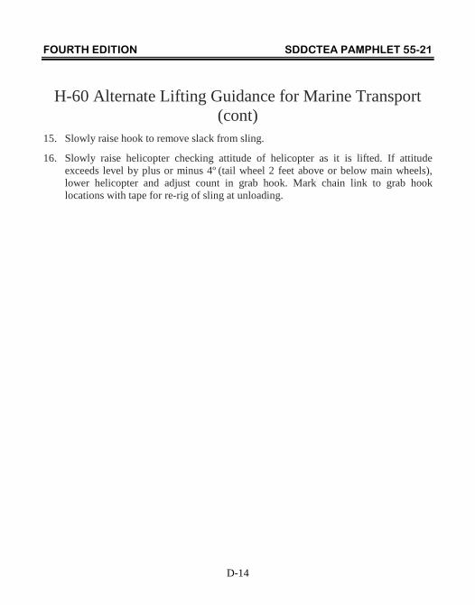
15. Slowly raise hook to remove slack from sling.
16. Slowly raise helicopter checking attitude of helicopter as it is lifted. If attitude exceeds level by plus or minus 4º (tail wheel 2 feet above or below main wheels), lower helicopter and adjust count in grab hook. Mark chain link to grab hook locations with tape for re-rig of sling at unloading.
FOURTH EDITION SDDCTEA PAMPHLET 55-21
D-15
H-60 Alternate Lifting Guidance for Marine Transport
FOURTH EDITION SDDCTEA PAMPHLET 55-21
D-16
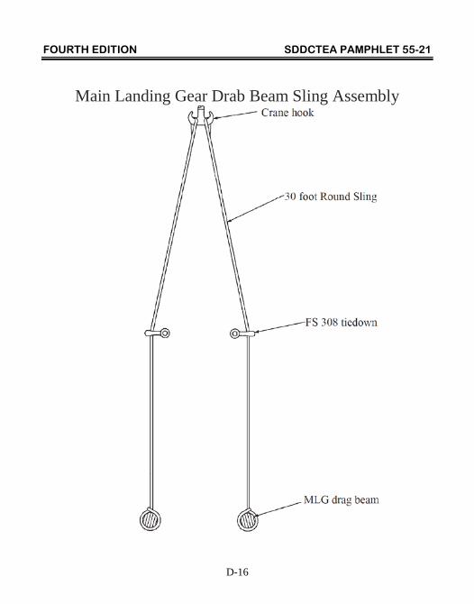
Main Landing Gear Drab Beam Sling Assembly
FOURTH EDITION SDDCTEA PAMPHLET 55-21
D-17
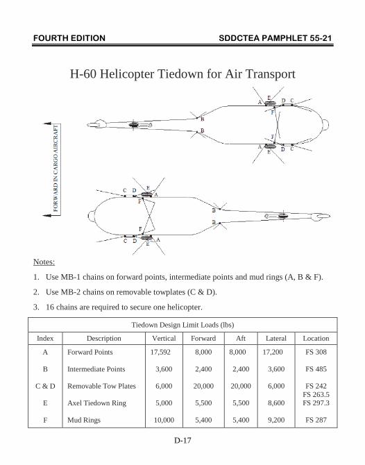
H-60 Helicopter Tiedown for Air Transport
Notes:
1. Use MB-1 chains on forward points, intermediate points and mud rings (A, B & F).
2. Use MB-2 chains on removable towplates (C & D).
3. 16 chains are required to secure one helicopter.
Tiedown Design Limit Loads (lbs)
Index Description Vertical Forward Aft Lateral Location
A
B
C & D
E
F
Forward Points Intermediate Points Removable Tow Plates Axel Tiedown Ring Mud Rings
17,592
3,600
6,000
5,000
10,000
8,000
2,400
20,000
5,500
5,400
8,000
2,400
20,000
5,500
5,400
17,200
3,600
6,000
8,600
9,200
FS 308
FS 485
FS 242 FS 263.5 FS 297.3
FS 287
FOURTH EDITION SDDCTEA PAMPHLET 55-21
D-18
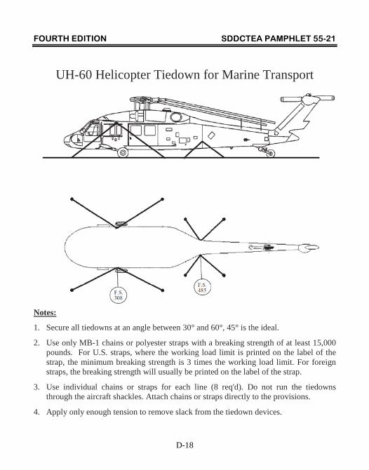
UH-60 Helicopter Tiedown for Marine Transport
Notes:
1. Secure all tiedowns at an angle between 30° and 60°, 45° is the ideal.
2. Use only MB-1 chains or polyester straps with a breaking strength of at least 15,000 pounds. For U.S. straps, where the working load limit is printed on the label of the strap, the minimum breaking strength is 3 times the working load limit. For foreign straps, the breaking strength will usually be printed on the label of the strap.
3. Use individual chains or straps for each line (8 req'd). Do not run the tiedowns through the aircraft shackles. Attach chains or straps directly to the provisions.
4. Apply only enough tension to remove slack from the tiedown devices.
FOURTH EDITION SDDCTEA PAMPHLET 55-21
D-19
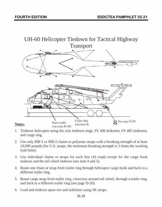
UH-60 Helicopter Tiedown for Tactical Highway Transport
Notes:
1. Tiedown helicopter using the axle tiedown rings, FS 308 tiedowns, FS 485 tiedowns, and cargo ring.
2. Use only MB-1 or MB-2 chains or polyester straps with a breaking strength of at least 10,000 pounds (for U.S. straps, the minimum breaking strength is 3 times the working load limit).
3. Use individual chains or straps for each line (16 reqd) except for the cargo hook tiedown and the tail wheel tiedown (see note 4 and 5).
4. Route one chain or strap from trailer ring through helicopter cargo hook and back to a different trailer ring.
5. Route cargo strap from trailer ring, crisscross around tail wheel, through a trailer ring, and back to a different trailer ring (see page D-20).
6. Load and tiedown spare tire and stabilator using 3K straps.
FOURTH EDITION SDDCTEA PAMPHLET 55-21
D-20
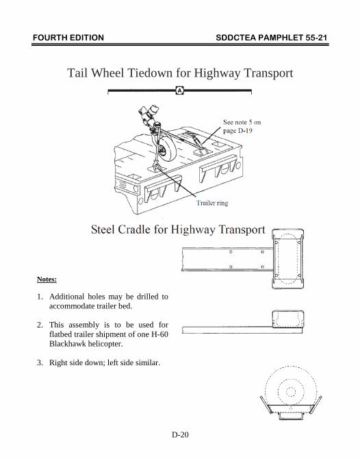
Tail Wheel Tiedown for Highway Transport
Notes: 1. Additional holes may be drilled to
accommodate trailer bed. 2. This assembly is to be used for
flatbed trailer shipment of one H-60 Blackhawk helicopter.
3. Right side down; left side similar.
FOURTH EDITION SDDCTEA PAMPHLET 55-21
D-21
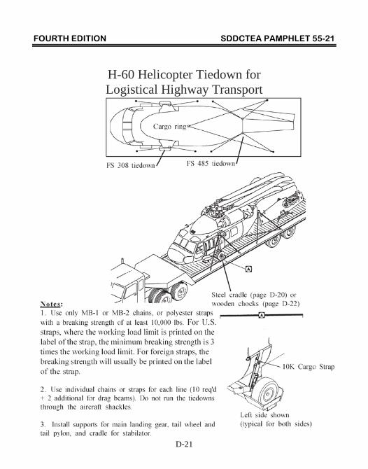
H-60 Helicopter Tiedown for Logistical Highway Transport
FOURTH EDITION SDDCTEA PAMPHLET 55-21
D-22
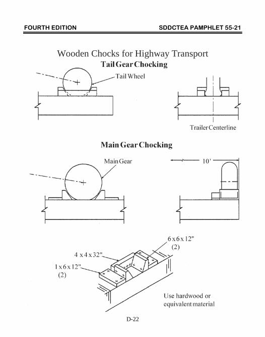
Wooden Chocks for Highway Transport
FOURTH EDITION SDDCTEA PAMPHLET 55-21
E-1
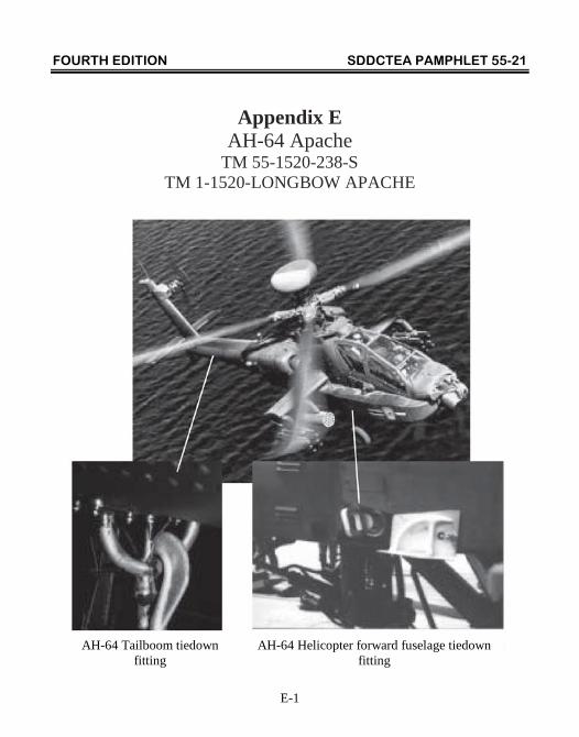
Appendix E AH-64 Apache
TM 55-1520-238-S TM 1-1520-LONGBOW APACHE
AH-64 Tailboom tiedown
fitting AH-64 Helicopter forward fuselage tiedown
fitting
FOURTH EDITION SDDCTEA PAMPHLET 55-21
E-2
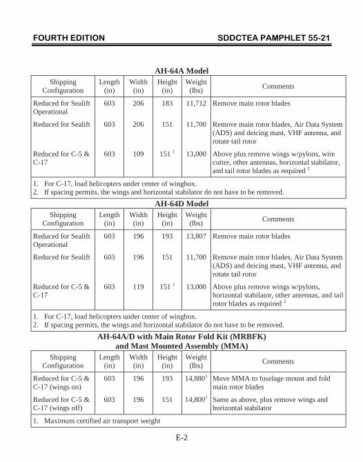
AH-64A Model Shipping
Configuration Length
(in) Width
(in) Height
(in) Weight
(lbs) Comments
Reduced for Sealift Operational
Reduced for Sealift
Reduced for C-5 & C-17
603
603
603
206
206
109
183
151
151 1
11,712
11,700
13,000
Remove main rotor blades
Remove main rotor blades, Air Data System (ADS) and deicing mast, VHF antenna, and rotate tail rotor
Above plus remove wings w/pylons, wire cutter, other antennas, horizontal stabilator, and tail rotor blades as required 2
1. For C-17, load helicopters under center of wingbox. 2. If spacing permits, the wings and horizontal stabilator do not have to be removed.
AH-64D Model Shipping
Configuration Length
(in) Width
(in) Height
(in) Weight
(lbs) Comments
Reduced for Sealift Operational
Reduced for Sealift
Reduced for C-5 & C-17
603
603
603
196
196
119
193
151
151 1
13,807
11,700
13,000
Remove main rotor blades
Remove main rotor blades, Air Data System (ADS) and deicing mast, VHF antenna, and rotate tail rotor
Above plus remove wings w/pylons, horizontal stabilator, other antennas, and tail rotor blades as required 2
1. For C-17, load helicopters under center of wingbox. 2. If spacing permits, the wings and horizontal stabilator do not have to be removed.
AH-64A/D with Main Rotor Fold Kit (MRBFK) and Mast Mounted Assembly (MMA)
Shipping Configuration
Length (in)
Width (in)
Height (in)
Weight (lbs) Comments
Reduced for C-5 & C-17 (wings on)
Reduced for C-5 & C-17 (wings off)
603
603
196
196
193
151
14,8801
14,8001
Move MMA to fuselage mount and fold main rotor blades
Same as above, plus remove wings and horizontal stabilator
1. Maximum certified air transport weight
FOURTH EDITION SDDCTEA PAMPHLET 55-21
E-3
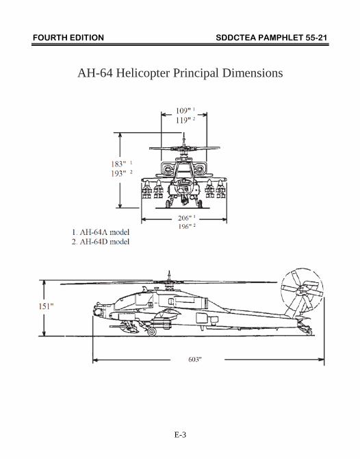
AH-64 Helicopter Principal Dimensions
FOURTH EDITION SDDCTEA PAMPHLET 55-21
E-4
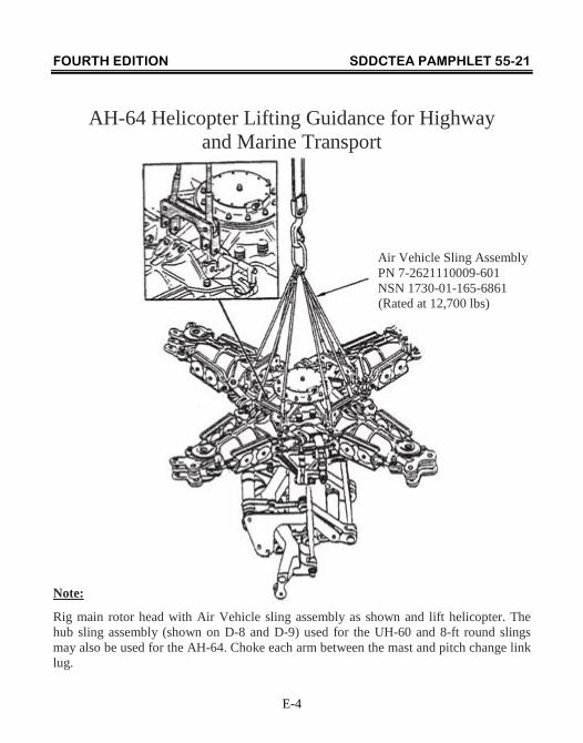
AH-64 Helicopter Lifting Guidance for Highway and Marine Transport
Air Vehicle Sling Assembly PN 7-2621110009-601 NSN 1730-01-165-6861 (Rated at 12,700 lbs)
Note:
Rig main rotor head with Air Vehicle sling assembly as shown and lift helicopter. The hub sling assembly (shown on D-8 and D-9) used for the UH-60 and 8-ft round slings may also be used for the AH-64. Choke each arm between the mast and pitch change link lug.
FOURTH EDITION SDDCTEA PAMPHLET 55-21
E-5
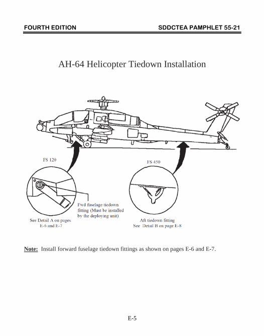
AH-64 Helicopter Tiedown Installation
Note: Install forward fuselage tiedown fittings as shown on pages E-6 and E-7.
FOURTH EDITION SDDCTEA PAMPHLET 55-21
E-6
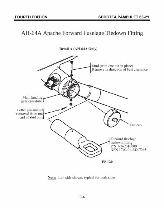
AH-64A Apache Forward Fuselage Tiedown Fitting
Note: Left side shown; typical for both sides.
FOURTH EDITION SDDCTEA PAMPHLET 55-21
E-7
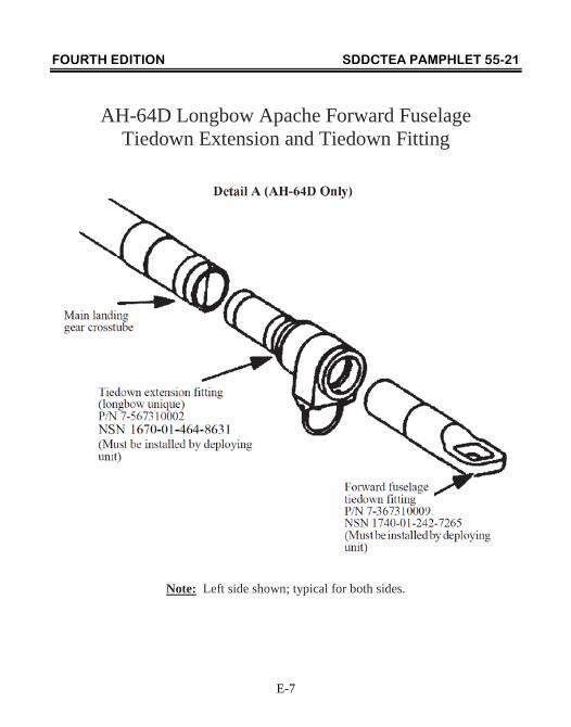
AH-64D Longbow Apache Forward Fuselage Tiedown Extension and Tiedown Fitting
Note: Left side shown; typical for both sides.
FOURTH EDITION SDDCTEA PAMPHLET 55-21
E-8
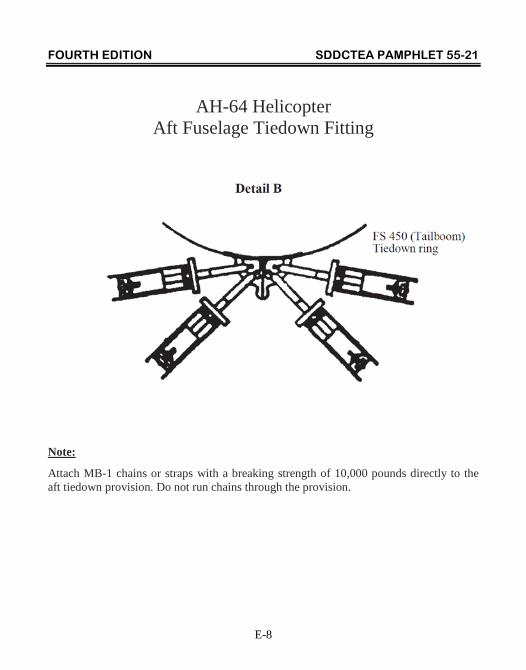
AH-64 Helicopter Aft Fuselage Tiedown Fitting
Note:
Attach MB-1 chains or straps with a breaking strength of 10,000 pounds directly to the aft tiedown provision. Do not run chains through the provision.
FOURTH EDITION SDDCTEA PAMPHLET 55-21
E-9
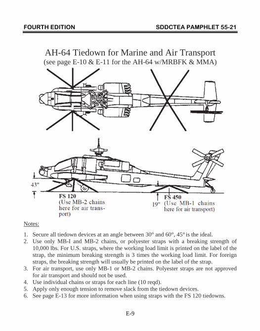
AH-64 Tiedown for Marine and Air Transport (see page E-10 & E-11 for the AH-64 w/MRBFK & MMA)
Notes:
1. Secure all tiedown devices at an angle between 30° and 60°, 45° is the ideal. 2. Use only MB-I and MB-2 chains, or polyester straps with a breaking strength of
10,000 lbs. For U.S. straps, where the working load limit is printed on the label of the strap, the minimum breaking strength is 3 times the working load limit. For foreign straps, the breaking strength will usually be printed on the label of the strap.
3. For air transport, use only MB-1 or MB-2 chains. Polyester straps are not approved for air transport and should not be used.
4. Use individual chains or straps for each line (10 reqd). 5. Apply only enough tension to remove slack from the tiedown devices. 6. See page E-13 for more information when using straps with the FS 120 tiedowns.
FOURTH EDITION SDDCTEA PAMPHLET 55-21
E-10
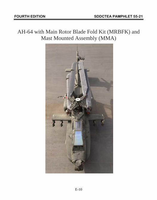
AH-64 with Main Rotor Blade Fold Kit (MRBFK) and Mast Mounted Assembly (MMA)
FOURTH EDITION SDDCTEA PAMPHLET 55-21
E-11
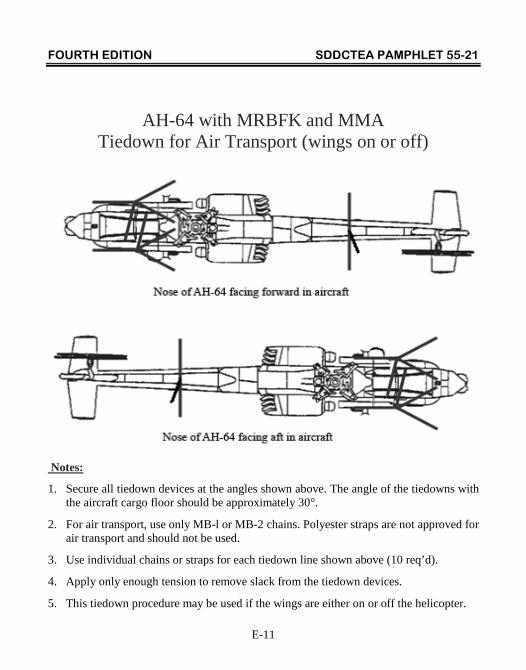
AH-64 with MRBFK and MMA Tiedown for Air Transport (wings on or off)
Notes:
1. Secure all tiedown devices at the angles shown above. The angle of the tiedowns with the aircraft cargo floor should be approximately 30°.
2. For air transport, use only MB-l or MB-2 chains. Polyester straps are not approved for air transport and should not be used.
3. Use individual chains or straps for each tiedown line shown above (10 req’d).
4. Apply only enough tension to remove slack from the tiedown devices.
5. This tiedown procedure may be used if the wings are either on or off the helicopter.
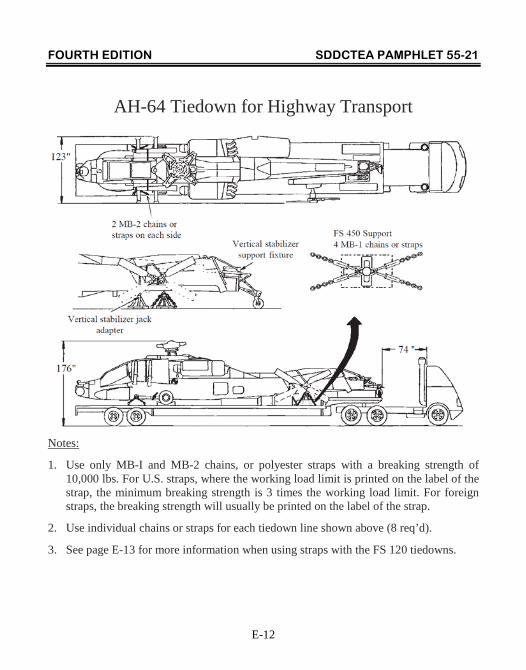
FOURTH EDITION SDDCTEA PAMPHLET 55-21
E-12
AH-64 Tiedown for Highway Transport
Notes:
1. Use only MB-I and MB-2 chains, or polyester straps with a breaking strength of 10,000 lbs. For U.S. straps, where the working load limit is printed on the label of the strap, the minimum breaking strength is 3 times the working load limit. For foreign straps, the breaking strength will usually be printed on the label of the strap.
2. Use individual chains or straps for each tiedown line shown above (8 req’d).
3. See page E-13 for more information when using straps with the FS 120 tiedowns.
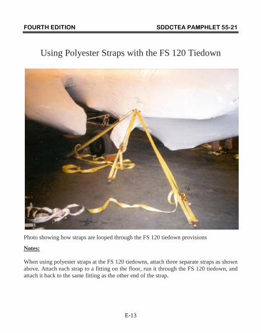
FOURTH EDITION SDDCTEA PAMPHLET 55-21
E-13
Using Polyester Straps with the FS 120 Tiedown
Photo showing how straps are looped through the FS 120 tiedown provisions
Notes: When using polyester straps at the FS 120 tiedowns, attach three separate straps as shown above. Attach each strap to a fitting on the floor, run it through the FS 120 tiedown, and attach it back to the same fitting as the other end of the strap.
FOURTH EDITION SDDCTEA PAMPHLET 55-21
Bibliography
TM 55-1520-242-S Preparation for Shipment of UH-1 Helicopters. TM 55-1520-241-S Preparation for Shipment of CH-47 Helicopters. TM 1-1520-248-S Preparation for Shipment of OH-58D
Helicopters. TM 1-1520-237-S Preparation for Shipment of UH-60 Helicopters. TM 55-1520-238-S Preparation for Shipment of AH-64A
Helicopters. TM 1-1520-Apache/ Interactive Electronic Technical Manual for the Longbow AH-64D TO 1C-5A-9-2 Supplemental Loading Instructions Manual Specific Procedures, Section IV: On/Off Loading Procedures for Helicopters TO 1C-17A-9 Preliminary Loading Instructions, Section VIC: Helicopters
FOURTH EDITION SDDCTEA PAMPHLET 55-21
Index
Model Page No. AH-64 Apache, Lifting ................................................................................. E-1 AH-64 Apache, Tiedown .............................................................................. E-5 CH-47 Chinook, Lifting ................................................................................ B-1 CH-47 Chinook, Tiedown ............................................................................. B-7 OH-58 Kiowa, Lifting ................................................................................... C-1 OH-58 Kiowa, Tiedown ................................................................................ C-11 UH-1 Iroquois, Lifting .................................................................................. A-1 UH-1 Iroquois, Tiedown ............................................................................... A-5 UH-60 Black Hawk, Lifting .......................................................................... D-1 UH-60 Black Hawk, Tiedown ...................................................................... D-17