
HELICOFLEX SPRING-ENERGIZED METAL SEALS
20
HELICOFLEX ® SPRING-ENERGIZED METAL SEALS WORLD CLASS SEALING TECHNOLOGY Source: Credit © CERN
Transcript of HELICOFLEX SPRING-ENERGIZED METAL SEALS

HELICOFLEX® SPRING-ENERGIZED METAL SEALSWORLD CLASS SEALING TECHNOLOGY
Source: Credit © CERN

3 SOLUTIONS THAT IMPROVE PERFORMANCE AND REDUCE COST-OF-OWNERSHIP THROUGHOUT THE PRODUCT LIFESPAN
1 SOLUTIONS ENGINEERED TO FIT YOUR EXACT SPECIFICATIONS
Introducing the HELICOFLEX® SealThe HELICOFLEX® seal is a resilient high performance metal seal that was created as part of a joint technical collaboration with
the French Atomic Energy Commission (CEA). Its incredible performance is a result of many years of research, experimentation
and practical application in key markets such as Nuclear, Physics Research, Chemical, Aerospace, Oil & Gas and Industrial.
HELICOFLEX® design flexibility allows Technetics engineers to customize the seal characteristics to match each unique application.
HELICOFLEX® SEALING CONCEPT
The sealing concept of the HELICOFLEX® seal is based on
viscoplastic deformation of a metallic lining. This lining is
selected based on its plasticity, which has to be softer than the
flange material. Such deformation is obtained by compressing a helical spring. The spring gives the HELICOFLEX® seal its
remarkable elasticity.
The use of a helical spring as the elastic core ensures an
outstanding level of adaptability to flange geometry and defects.
THE CHOICE OF THE SPRING CHARACTERISTICS ALLOWS:
• To adjust compression load based on type of lining
material and required sealing level.
• To control the load needed to ensure a permanent
contact between the flanges.
PLASTICITY
RESILIENCY
ALL METAL
GENERAL CHARACTERISTICS
• DN 4 to 8000 mm
• Ø 1,5 to 40 mm cross section
• Sealing level from bubble tightness
down to 10 -12 Pa.m3.s-1
• Temperature from -272° up to 800°C
• Pressure from 10 -10 mbar up to 3000 bar
• Very good resistance to radiation
• Very good resistance to corrosion
• Extended life time
• Adaptable to all types of sealing surfaces
(FF, RF,TG, Groove,….)
(3 faces, radial, shaped,…)
• Adaptable to all flange standards
(PNEUROP,ANSI, ISO,…)

SOLUTIONS THAT IMPROVE PERFORMANCE AND REDUCE COST-OF-OWNERSHIP WORLD CLASS SEALING TECHNOLOGY 2
THE CHOICE OF THE SPRING CHARACTERISTICS ALLOWS:
material and required sealing level.
contact between the flanges.
ADVANTAGES OF THE
METAL/METAL CONTACT
• Optimized compression
• Minimum elastic deformation required
• Rigid assembly
• Excellent withstanding to thermal transients
Metal to Metal AssemblyThe metal to metal assembly consists in generating a solid mechanical contact independent of the active part of the seal.
The seal elasticity is exclusively dedicated to maintaining the sealing. This concept protects the seal from over tightening.
CONTROL OF THE COMPRESSION
The HELICOFLEX® seal requires, in case of a static sealing application,
controlled compression either by
means of a groove A or by means of
a built-in compression limiter B. In
case of a semi-static application, it
requires a controlled seating load C.
BEFORE TIGHTENING
AFTER TIGHTENING
BEFORE TIGHTENING
A
HN HN
B
HL Helicodur
HL Helicodur
B
HN HN
B
HN HN
A
HNDEHNDE Composite Double Section
C
Controlled LoadHND HND
AFTER TIGHTENING

3 SOLUTIONS THAT IMPROVE PERFORMANCE AND REDUCE COST-OF-OWNERSHIP THROUGHOUT THE PRODUCT LIFESPAN
3 SOLUTIONS ENGINEERED TO FIT YOUR EXACT SPECIFICATIONS
Advanced Sealing for Critical Applications
BASIC VERSION
Standard circular
Cross Section (C.S.)
ADAPTABILITY BY THE DESIGN FLEXIBILITY
N.mm-r
Y2
e2
Y0
USED IN MOST CASES WITH:
• single or double lining
• single or double C.S.
In the various types or shapes mentioned in pages 7 to 16
HELICOFLEX® HN
ADAPTABILITY BY THE SEAL GEOMETRY
The seal section is oval and allows its use in
trapezoidal grooves in place of RTJ gaskets
The grinding of the spring according to an angle ß
perfectly gives the possibility to modulate the seal tightness
Particular shape of the seal resulting in a lower point for initial sealing level Yo as well
as for sealing point Y2
Has an internal limiter to control the compression
Used in a non metal to metal assembly
Accepts a retightening
HLO HNR
HL HNV
ÉO
Y2
Y0
N.mm-IY2
Y0
ÉO
N.mm-I
ÉO
Y2
Y0
N.mm-I
ÉO
Y2
Y2
Y0
N.mm-I
ß 360°
ß 180°
Wire Section§
GROOVE
CONICAL FLANGE 3 FACES CONTACT POPPET VALVE BUTTERFLY VALVE LEAK CHECK
TONGUE & GROOVE RAISED FACE RADIAL
Advanced Sealing for Critical Applications

SOLUTIONS THAT IMPROVE PERFORMANCE AND REDUCE COST-OF-OWNERSHIP WORLD CLASS SEALING TECHNOLOGY 4
ADAPTABILITY BY THE MATERIAL CHOICE
Sealing lining: Aluminum - Gold - Silver - Iron - Copper - Brass - Soft Steel - Nickel - Monel - Tantalum
Stainless Steel (304L - 316L - 321 - 316 Ti) - Zirconium - Inconel (600 - 625) - Hastelloy - Titanium - Tin
Special materials on demand
Coatings: Gold - Silver - Tin - Nickel - FEP
Spring: Nimonic 90 - Alloy 718 - Alloy 750 - SS - XC80
ADAPTABILITY TO THE APPLICATION
Also for: Pneurop flanges, for conical flanges, for remote handling, for valves.
• HELICOFLEX®/RUBBER SECTION
• DOUBLE HELICOFLEX® SECTION
• SEAL WITH SPACER
• SEAL WITH LEAK CHECK
• VERY LARGE SEAL
• SEAL WITH RIB
• SEAL WITH CLIP
• SHAPED SEAL, RACE TRACK, OBLONG,
SQUARE, WITH PTFE COATING
Demanding Environments
NUCLEAR (NPP)
NUCLEAR (FUEL CYCLE)
CRYOGENICS
AUTOMOTIVE
AEROSPACE
CHEMICAL/PETROCHEMICAL
SEMICONDUCTOR
NEW NUCLEAR REACTORRESEARCH
Source: Credit © CERN

3 SOLUTIONS THAT IMPROVE PERFORMANCE AND REDUCE COST-OF-OWNERSHIP THROUGHOUT THE PRODUCT LIFESPAN
5 SOLUTIONS ENGINEERED TO FIT YOUR EXACT SPECIFICATIONS
SEALING CRITERIA
The characteristic values given in this catalog are designed
to meet 2 distinct sealing criteria.
• The “bubble tight” sealing corresponding to a gaseous flow of air
≤ 10 -5 Pa.m3.s-1 (10 -4 atm.cm3.sec-1) under 1 bar ∆P.
• The Helium sealing corresponding to a gaseous flow of Helium
≤ 10 -10 Pa.m3.s-1 (10 -9.atm.cm3.sec-1) under 1 bar ∆P. Some lower
gas flow (10 -12 Pa.m3.s-1) can be achieved according to the choice
of the lining, but that requires a super polishing of seal and
sealing surfaces.
The choice of sealing criteria according to the different assembly requirements (gas sealing, liquid sealing, toxicity, pollution,…) must be done before designing the assembly due
to the consequences.
SHAPE SEALS (RECTANGULAR, OBLONG, ...) FOR USE ON MACHINED SURFACE
The surfaces, using shape seals, are obtained with processes less favorable to the sealing performance than lathe
machining. By consequence, the seal requires a design, compared to the circular seal,with a stiffer spring . For non circular seals, the sealing surface finish has to be better whatever the lining (Ra = 0,4 à 0,8 μm). In case the roughness can not be obtained, a specific tool generating preferential polishing lines can be recommended.
Design Considerations
* Average value to adjust according to the cross section.
FLATNESS TOLERANCE
Thanks to its spring concept, the HELICOFLEX® seal accepts
flatness defects. The following flatness tolerances can be acceptable on the flange assembly (cumulated value for both flanges). A local defect could generate a lack of compression that shall not exceed 20% of the nominal value.
Dimensions Amplitude* Tangential* Radial* slope
DN 10 to 500 0,2 mm 0,1/100 1/100
DN 500 to 2000 0,4 mm 0,2/100 2/100
DN 2000 to 5000 0,8 mm 0,5/100 3/100
SURFACE FINISH
The sealing level of the HELICOFLEX® seal is directly and closely related to the quality of the surface finish of the sealing areas. The sealing surface finish is critical from both roughness and method of machining standpoints. Lathe finishes have to be recommended for circular seals ; milling should be avoided. The below table summarizes these recommendations.
not recommended (please consult us) correct values acceptable correct values recommended
Note: The sealing areas must be turned by lathe. It is not recommended to try to get the required roughness by polishing with abrasive paper.
This process must be reserved for refurbishing damaged sealing surface. This polishing has to be done in the same circular way as machining by lathe.
• Circular seals for use on turned surface
N° LCA - CEA N10 N9 N8 N7 N6 N5 N4
Ra in μm 12,5 6,3 3,2 1,6 0,8 0,4 0,2
Rt in μm 50 37 21 11 6,2 3,4 1,9
μ. inches 500 250 125 63 32 16 8
Plating (Pb, Sn, In) PTFE - FEP
Aluminum
Silver, copper, iron
Nickel, stainless steel

SOLUTIONS THAT IMPROVE PERFORMANCE AND REDUCE COST-OF-OWNERSHIP WORLD CLASS SEALING TECHNOLOGY 6
LOAD VERSUS DEFLECTION CURVE
The compression and decompression cycle of the HELICOFLEX® seal shows a progressive flattening of the curve. The position of this step is selected according to the required sealing and the lining material.
VALUES TO TAKE INTO ACCOUNT FOR THE HELICOFLEX® CALCULATION (PAGE 12)
Refer to tables, page 7, for standard seals and page 15 for HELICOFLEX® delta HNV. Consult us for all other specific seals
(HELICOFLEX® beta HNR, shape seals, Omicron,…) The Y2, e2, ec, Y1 values are directly readable in the tables.
For Ө1 < Ө < Ө2,PuӨ1 and PuӨ2 allow to linearly interpolate PuӨ with a safety margin. Ym is calculated with P, Pu Ө, Y1, Y2 (see page 12).
Y0 = Linear load from where the required
sealing level is obtained.
Y2= Linear load to reach the seating point
and the metal to metal contact.
e2= Compression value to get the metal to metal contact. It is related to the linear
load Y2 and determines the groove depth.
ec= Critical compression value beyond which
the sealing level could deteriorate.
Ym(I)= Minimum linear load to maintain sealing
in service. It varies according to the
pressure and the temperature.
em(I)= Compression values related to Ym below
which the sealing level is lost.
(I) = Function of P & T.
Pu = Maximum pressure: it is the maximum
pressure that the seal can withstand
at a certain temperature.
Pu 20˚= Maximum pressure at room temperature (20°C)
Pu Ө= Maximum pressure at service temperature.
Өmaxi= This value allows the Ym calculation.
Temperature where Pu Ө is close to zero.
PRESSURE/TEMPERATURE CHART
Characteristic Values
ece2em
Ym
e1
Y1
Y0
Y2
e0
Nmm-1
Pu
20∞C
Puθ
20∞ θ ∞Cθmaxi

3 SOLUTIONS THAT IMPROVE PERFORMANCE AND REDUCE COST-OF-OWNERSHIP THROUGHOUT THE PRODUCT LIFESPAN
7 SOLUTIONS ENGINEERED TO FIT YOUR EXACT SPECIFICATIONS
Table of Characteristic Values(standard HN, axial compression)
C.S. mm
COMPRESSION HELIUM SEALING BUBBLE SEALINGT°C
maxi RECOMMENDED SURFACE
FINISHe2
mmec
mmY2
N.mm-1
Y1 N.mm-1
Pu20° MPa
PuӨ 200° MPa
Y2 N.mm-1
Y1 N.mm-1
Pu 20° MPa
PuӨ 200° MPa
°C
1,6 (1,6 à 1,8) 0,6 ± 0,05 0,7 150 20 50 - 90 20 35 - 150
1,6
to
3,2
μm
2 (1,9 à 2,1) 0,7 ± 0,1 0,85 160 20 52 - 100 20 40 - 150
2,2 (2,2 à 2,4) 0,7 ± 0,1 0,9 165 20 53 - 105 20 40 - 180
2,6 (2,5 à 2,9) 0,7 ± 0,1 0,9 175 20 55 5 115 20 42 5 220
3 (3 à 3,4) 0,8 ± 0,1 1 185 25 55 10 130 20 45 10 250
3,5 (3,5 à 3,9) 0,8 ± 0,1 1 190 25 55 14 140 20 47 14 250
4 (4 à 4,4) 0,9 ± 0,1 1,1 200 25 60 17 150 20 50 17 280
4,5 (4,5 à 4,9) 0,9 ± 0,1 1,2 210 25 60 20 160 20 52 20 280
5,1 (5 à 5,4) 0,9 ± 0,1 1,4 220 30 63 22 170 25 55 22 300
5,6 (5,5 à 5,9) 0,9 ± 0,1 1,6 230 30 65 24 180 25 57 24 320
6,6 (6 à 6,9) 1 ± 0,1 1,8 245 35 67 25 195 30 60 25 340
7,6 (7 à 7,9) 1 ± 0,1 2,2 270 40 70 28 205 35 65 28 340
8,6 (8 à 8,9) 1 ± 0,1 2,6 290 50 72 32 225 40 68 31 360
9,8 (9 à 9,9) 1 ± 0,1 3 325 55 75 33 235 50 72 32 380
10,8 (10 à 10,9) 1,1 ± 0,1 3,5 350 60 75 36 245 50 73 33 380
11,8 (11 à 12,9 1,1 ± 0,1 3,8 375 70 80 38 255 60 77 35 400
14,2 (13 à 14,9) 1,2 ± 0,15 4,6 400 80 82 40 295 65 80 36 400
16,2 (15 à 16,9) 1,3 ± 0,15 5,4 465 90 84 42 345 75 82 38 430
18,2 (17 à 18,9) 1,5 ± 0,15 6,2 540 110 85 43 400 90 82 39 430
19 à 25 2 ± 0,2 7 725 130 90 45 550 100 85 40 450
26 à 30 2,8 ± 0,25 9 925 190 90 45 700 150 85 40 450
31 à 40 3,5 ± 0,3 12 1160 250 90 45 900 200 85 40 450
LINING: ALUMINUM GOLD
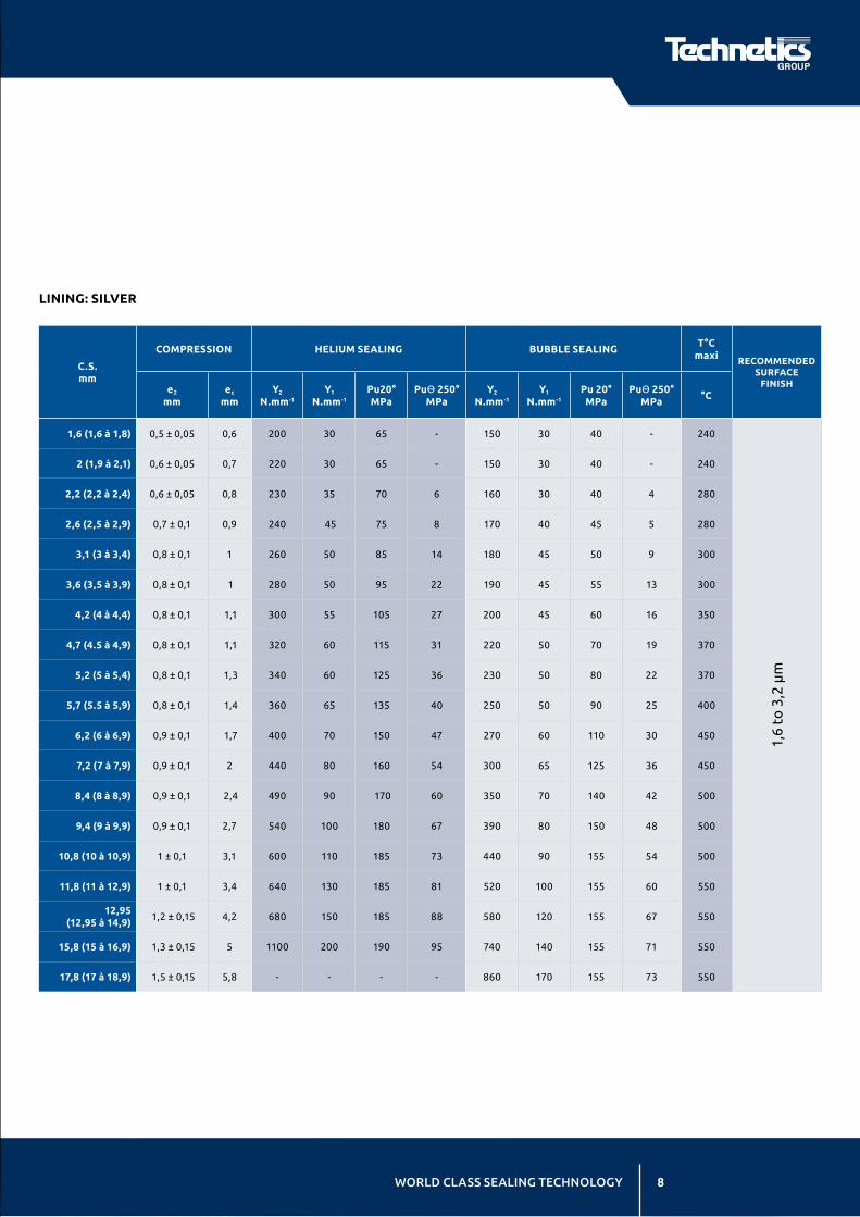
SOLUTIONS THAT IMPROVE PERFORMANCE AND REDUCE COST-OF-OWNERSHIP WORLD CLASS SEALING TECHNOLOGY 8
C.S. mm
COMPRESSION HELIUM SEALING BUBBLE SEALINGT°C
maxi RECOMMENDED SURFACE
FINISHe2
mmec
mmY2
N.mm-1
Y1
N.mm-1
Pu20° MPa
PuӨ 250°
MPaY2
N.mm-1
Y1
N.mm-1
Pu 20° MPa
PuӨ 250°
MPa°C
1,6 (1,6 à 1,8) 0,5 ± 0,05 0,6 200 30 65 - 150 30 40 - 240
1,6
to 3
,2 μ
m
2 (1,9 à 2,1) 0,6 ± 0,05 0,7 220 30 65 - 150 30 40 - 240
2,2 (2,2 à 2,4) 0,6 ± 0,05 0,8 230 35 70 6 160 30 40 4 280
2,6 (2,5 à 2,9) 0,7 ± 0,1 0,9 240 45 75 8 170 40 45 5 280
3,1 (3 à 3,4) 0,8 ± 0,1 1 260 50 85 14 180 45 50 9 300
3,6 (3,5 à 3,9) 0,8 ± 0,1 1 280 50 95 22 190 45 55 13 300
4,2 (4 à 4,4) 0,8 ± 0,1 1,1 300 55 105 27 200 45 60 16 350
4,7 (4.5 à 4,9) 0,8 ± 0,1 1,1 320 60 115 31 220 50 70 19 370
5,2 (5 à 5,4) 0,8 ± 0,1 1,3 340 60 125 36 230 50 80 22 370
5,7 (5.5 à 5,9) 0,8 ± 0,1 1,4 360 65 135 40 250 50 90 25 400
6,2 (6 à 6,9) 0,9 ± 0,1 1,7 400 70 150 47 270 60 110 30 450
7,2 (7 à 7,9) 0,9 ± 0,1 2 440 80 160 54 300 65 125 36 450
8,4 (8 à 8,9) 0,9 ± 0,1 2,4 490 90 170 60 350 70 140 42 500
9,4 (9 à 9,9) 0,9 ± 0,1 2,7 540 100 180 67 390 80 150 48 500
10,8 (10 à 10,9) 1 ± 0,1 3,1 600 110 185 73 440 90 155 54 500
11,8 (11 à 12,9) 1 ± 0,1 3,4 640 130 185 81 520 100 155 60 550
12,95 (12,95 à 14,9)
1,2 ± 0,15 4,2 680 150 185 88 580 120 155 67 550
15,8 (15 à 16,9) 1,3 ± 0,15 5 1100 200 190 95 740 140 155 71 550
17,8 (17 à 18,9) 1,5 ± 0,15 5,8 - - - - 860 170 155 73 550
LINING: SILVER

3 SOLUTIONS THAT IMPROVE PERFORMANCE AND REDUCE COST-OF-OWNERSHIP THROUGHOUT THE PRODUCT LIFESPAN
9 SOLUTIONS ENGINEERED TO FIT YOUR EXACT SPECIFICATIONS
Table of Characteristic Values (Continued)(standard HN, axial compression)
C.S. mm
COMPRESSION HELIUM SEALING BUBBLE SEALINGT°C
maxi RECOMMENDED SURFACE
FINISHe2
mmec
mmY2
N.mm-1
Y1 N.mm-1
Pu20° MPa
PuӨ 300° MPa
Y2 N.mm-1
Y1 N.mm-1
Pu 20° MPa
PuӨ 300° MPa
°C
1,7 (1,6 à 1,8) 0,5±0,05 0,6 260 40 50 10 190 30 35 5 350
z1,6
to
3,2
μm
1,9 (1,9 à 2,1) 0,6±0,5 0,7 280 50 50 11 200 40 35 6 350
2,34 (2,2 à 2,4) 0,6±0,5 0,8 300 60 55 13 220 50 35 8 360
2,74 (2,5 à 2,9) 0,7±0,1 0,9 320 70 60 17 230 60 40 10 380
3,24 (3 à 3,4) 0,7±0,1 1 350 80 65 20 250 70 40 12 380
3,84 (3,5 à 3,9) 0,7±0,1 1 390 80 70 23 270 70 45 15 400
4,34 (4 à 4,4) 0,8±0,1 1,1 430 90 70 27 290 80 45 17 420
4,84 (4,5 à 4,9) 0,8±0,1 1,1 470 100 80 30 320 80 45 19 450
5,34 (5 à 5,4) 0,8±0,1 1,3 510 110 85 33 330 90 50 21 450
5,84 (5,5 à 5,9) 0,8±0,1 1,4 550 120 90 36 360 100 50 23 480
6,34 (6 à 6,9) 0,9±0,1 1,7 630 140 95 40 420 100 55 26 520
7,54 (7 à 7,9) 0,9±0,1 2 740 160 100 45 460 110 60 29 520
8,54 (8 à 8,9) 0,9±0,1 2,4 860 190 110 49 530 130 65 32 550
9,94 (9 à 9,9) 0,9±0,1 2,7 990 220 150 52 600 140 70 35 580
10,94 (10 à 10,9)
1±0,1 3,1 - - - - 670 160 75 37 580
LINING: COPPER, SOFT IRON, MILD STEEL

SOLUTIONS THAT IMPROVE PERFORMANCE AND REDUCE COST-OF-OWNERSHIP WORLD CLASS SEALING TECHNOLOGY 10
C.S. mm
COMPRESSION HELIUM SEALING BUBBLE SEALINGT°C
maxi RECOMMENDED SURFACE
FINISHe2
mmec
mmY2
N.mm-1
Y1 N.mm-1
Pu20° MPa
PuӨ 250° MPa
Y2 N.mm-1
Y1 N.mm-1
Pu 20° MPa
PuӨ 250° MPa
°C
1,6 (1,6 à 1,8) 0,4 ± 0,05 0,5 320 80 70 11 200 60 40 7 380
0,8
to
1,6
μm
2 (1,9 à 2,1) 0,5 ± 0,05 0,6 350 80 72 16 220 60 42 9 380
2,4 (2,2 à 2,4) 0,5 ± 0,05 0,7 390 90 76 21 230 70 44 12 420
2,6 (2,5 à 2,9) 0,6 ± 0,05 0,8 450 100 82 27 270 70 47 16 450
3,2 (3 à 3,4) 0,6 ± 0,05 0,9 440 110 87 34 300 80 50 20 480
3,7 (3,5 à 3,9) 0,6 ± 0,05 0,9 580 120 93 40 340 90 54 23 500
4,2 (4 à 4,4) 0,7 ± 0,1 1 640 140 96 45 380 100 57 27 550
4,7 (4,5 à 4,9) 0,7 ± 0,1 1 700 150 105 52 420 110 60 30 600
5,2 (5 à 5,4) 0,7 ± 0,1 1,1 780 180 110 57 460 110 65 33 650
5,9 (5,5 à 5,9) 0,7 ± 0,1 1,3 850 200 115 62 500 120 67 37 650
6,4 (6 à 6,9) 0,8 ± 0,1 1,6 - - - - 560 130 72 41 650
7,4 (7 à 7,9) 0,8 ± 0,1 1,8 - - - - 650 150 78 45 650
8,4 (8 à 8,9) 0,8 ± 0,1 2,1 - - - - 730 160 83 50 650
9,8 (9 à 9,9) 0,8 ± 0,1 2,4 - - - - 820 170 87 53 650
10,94 (10 à 10,9)
0,9 ± 0,1 2,7 - - - - 920 200 90 56 650
LINING: NICKEL, MONEL, TANTALUM

3 SOLUTIONS THAT IMPROVE PERFORMANCE AND REDUCE COST-OF-OWNERSHIP THROUGHOUT THE PRODUCT LIFESPAN
11 SOLUTIONS ENGINEERED TO FIT YOUR EXACT SPECIFICATIONS
C.S. mm
COMPRESSION HELIUM SEALING BUBBLE SEALINGT°C
maxi RECOMMENDED SURFACE
FINISHe2
mmec
mmY2
N.mm-1
Y1 N.mm-1
Pu20° MPa
PuӨ 400° MPa
Y2 N.mm-1
Y1 N.mm-1
Pu 20° MPa
PuӨ 400° MPa
°C
1,6 (1,6 à 1,8) 0,4 ± 0,05 0,7 350 100 90 25 300 80 47 6 420
0,8
to 1
,6 μ
m
2 (1,9 à 2,1) 0,5 ± 0,05 0,85 400 100 91 27 320 80 50 8 420
2,4 (2,2 à 2,4) 0,5 ± 0,05 0,9 450 110 92 29 350 90 52 11 480
2,6 (2,5 à 2,9) 0,6 ± 0,05 0,9 500 120 97 32 380 100 57 15 500
3,2 (3 à 3,4) 0,6 ± 0,05 1 575 130 100 36 425 110 62 20 500
3,7 (3,5 à 3,9) 0,6 ± 0,05 1 660 150 104 39 470 130 67 25 550
4,2 (4 à 4,4) 0,7 ± 0,1 1,1 750 170 107 42 520 150 72 30 600
4,7 (4,5 à 4,9) 0,7 ± 0,1 1,2 825 220 110 45 560 180 77 34 650
5,2 (5 à 5,4) 0,7 ± 0,1 1,4 - - - - 600 190 82 37 700
5,9 (5,5 à 5,9) 0,7 ± 0,1 1,6 - - - - 650 200 87 42 700
6,4 (6 à 6,9) 0,8 ± 0,1 1,8 - - - - 720 220 94 47 700
7,4 (7 à 7,9) 0,8 ± 0,1 2,2 - - - - 800 260 102 52 700
8,4 (8 à 8,9) 0,8 ± 0,1 2,6 - - - - 900 290 108 58 700
9,8 (9 à 9,9) 0,8 ± 0,1 3 - - - - 1000 340 115 62 700
10,6 (10 à 10,9) 0,9 ± 0,1 3,5 - - - - 1070 370 120 66 700
LINING: STAINLESS, INCONEL, TITANIUM, ZIRCONIUM
Please consult us for materials not listed and coated seals
(Gold, Silver, Tin, Nickel, FEP).
• For the HELICOFLEX® beta HNR see page 16.
• For HELICOFLEX® delta HNV, see page 15.
• For radial or 3 faces compression,see page 14.
Table of Characteristic Values (Continued)(standard HN, axial compression)

SOLUTIONS THAT IMPROVE PERFORMANCE AND REDUCE COST-OF-OWNERSHIP WORLD CLASS SEALING TECHNOLOGY 12
The tightening load for a HELICOFLEX® seal can be calculated according to the CODAP (Annexe C6A4)
or by analogy with the calculation done for the flat gaskets.
WE CAN SUPPLY CALCULATION DATA SHEET ACCORDING TO THE FOLLOWING PROCESS:
Calculation Data for HELICOFLEX® Seal
PARAMETERS FORMULA UNITS
Dj
Y2
Y1
P
Et20°
Ets
Pu
PuӨ
Mean diameter of the seal
Linear seating load of the seal
Threshold of sealing lost at 20°C/1bar
Calculation pressure (working, design or test)
Young modulus of the bolt material at 20°C
Young modulus of the bolt material at calculation temperature
Max pressure at 20°C
Max pressure at design P & T
N
N
N.mm-1
N
N
N
N
N
CALCULATION OF THE MINIMUM TIGHTENING LOAD FORMULA UNITS
P
d2
Dm
μ
Cs
Cs
Pitch of the bolt
Diameter on thread side
Diameter of the contact under the screw head
Friction coefficient of the screw and the nut
Torque value in N.mm
Torque value in N.m
= FB/Nbx(0,16xp+μx(0,58xd2+Dm/2))
= Cs (N.mm)/1000
mm
mm
mm
N.mm
N.m
CALCULATION OF THE BOLT STRESS FORMULA UNITS
SB
Nb
a
ts
Resistant section of the bolt
Number of bolts
Stress in the bolts at room temperature
Stress in the bolts at calculation temperature
= FB x Nb / SB
= a x Ets / Et20°
mm2
MPa
MPa
CALCULATION OF THE MINIMUM TIGHTENING LOAD FORMULA UNITS
Fj
FF
Ym
Fm
Fs
Fs*
FB1
FB2
Seating load of the seal
Hydrostatic force from the pressure
Minimum linear load to keep the sealing
Minimum load to keep the sealing
Total load to insure the sealing
Total load taking into account the young modulus compensation
FB1
is the minimum load to be applied on the
assembly in order to reach the target leak rate
Min. load for metal-to-metal contact
FB2
= k.max{Fs*,Fj} with Fs=Ff+Fj => Fb2 = k.(Ff+Fj).E/ET
= π x Dj xY2 X1,1
= π/4 x Dj2 x P
= Max (Y1 ;Y2 x P/PuӨ)
= π x Dj x Ym
= Ff + Fm
= Fs x Et20°c/Ets*
= Max (Fj ; FS*)
N
N
N.mm-1
N
N
N
N
N
The tightening load FB2
ensures the metal-to-metal contact (flange to flange) in operating condition. If allowed
by the assembly, this is the recommended tightening load. The load above is not the only parameter to take
into account to design the assembly. For instance, the calculations do not take into account any other external
load (e.g. moment on the assembly). For questions, please contact our engineering department.

3 SOLUTIONS THAT IMPROVE PERFORMANCE AND REDUCE COST-OF-OWNERSHIP THROUGHOUT THE PRODUCT LIFESPAN
13 SOLUTIONS ENGINEERED TO FIT YOUR EXACT SPECIFICATIONS
Design ConsiderationsDimensions of the seals according to the assembly.
AXIAL COMPRESSION
RADIAL COMPRESSION
A radial compression is possible with
HELICOFLEX® seal by using the adapted
types : HN 110, 210, 160, 180. The system
offers the option of internal or external compression The internal compression
expands the inner diameter and the
external compression restrains the
outside diameter.
The main precautions to take concern the
material to be used and the roughness
of the surface finish of the sealing area which must be smooth (Ra ≤ 0,8 mm) and lubricated during the assembly with a spray
(PTFE, graphite, Molybdene, silicone, oil)
compatible with the media.
The seal should be maintained in its housing
with axial contact. The compression has to
be progressive ≤ 0,1 mm per mm of motion.
g = Ø C.S. + e3 + 0,2
I = 10e3
Ø C = Seal OD
Ø B ≤ Seal ID - 1 mini
Ø A = Ø + 2e3
Ø B ≥ Seal OD + 1 mini Ø A = Ø - 2e3
Ø C = Seal ID
External Pressure P ≥ 20 bars
Same concept with internal back up.
It is the groove ID which has to contact
& support the seal
External or Internal Pressure P < 20 bars
The seal can be centered in the
groove without radial contact with
a minimum groove width
w ≥ Seal cross section + 2e2 + 0,5 mm.
SILVER COPPER NICKEL STAINLESS STEEL
Ø mm
e3 mm
Ya N.mm-1
Ø mm
e3 mm
Ya N.mm-1
Ø mm
e3 mm
Ya N.mm-1
Ø mm
e3 mm
Ya N.mm-1
1,6 0,25 30 1,7 0,20 38 1,6 0,20 40 1,6 0,20 60
2,6 0,30 34 2,34 0,25 44 2,6 0,25 54 2,6 0,25 76
3,1 0,35 36 3,24 0,30 50 3,2 0,30 60 3,2 0,30 84
4,2 0,45 40 4,34 0,40 58 4,2 0,40 76 4,2 0,40 104
5,2 0,45 46 5,34 0,40 66 5,2 0,40 92 5,2 0,40 120
6,2 0,50 54 6,34 0,45 80 6,4 0,45 112 6,4 0,45 144
8,4 0,50 70 8,54 0,45 106 8,4 0,45 146 8,4 0,45 180
10,8 0,60 88 10,94 0,50 134 10,6 0,50 184 10,6 0,50 214
Internal Pressure P ≥ 20 bars
• Groove assembly : at the end of compression
the seal should be in contact with and
supported by the groove wall opposed to the
pressure side.
h = d - e2
Internal pressure:
Ø B = OD - J
Ø A ≥ ID + 2e2 + 0,5
J = clearance between seal OD and Groove OD
J = f (d) (see table)
J Ø d (C.S.)
0,3 1,5 à 3,4
0,5 3,5 à 6,9
0,7 7 à 9,9
0,9 > 10

SOLUTIONS THAT IMPROVE PERFORMANCE AND REDUCE COST-OF-OWNERSHIP WORLD CLASS SEALING TECHNOLOGY 14
3 FACE COMPRESSION
D= shaft¯ +2 h
60°TypeH N
h
e60¡
¯ b+0-0,05
100-200(120-220)
J
J≤C.S./10
h
Section D
30° 45° 60°
Aluminum Other Linings Aluminum Other Linings Aluminum Other Linings
2,6
3,2
4,2
5,2
6,4
8,4
10,6
3,30
4,00
5,25
6,60
8,15
10,90
13,80
3,20
4,00
5,25
6,60
8,15
10,90
13,80
4,15
5,05
6,60
8,30
10,20
13,60
17,25
4,15
5,05
6,60
8,30
10,20
13,60
17,25
3,20
4,00
5,40
6,90
8,60
11,60
14,80
3,40
4,20
5,60
7,10
8,80
11,80
15,00
Note: These values take into account the lining overlap (30° et 45°)
CHARACTERISTIC VALUES
The axial linear tightening load Ya and compression value e, can be obtained
from Y2 and e2 values given page 7, corrected by factors K and a.
Axial linear load:
• Y0 = KY2
Axial compressive movement:
• e = a e2
Coefficient 30° 45° 60°
a 2 1,4 1,15
k 0,9 1,2 1,4

3 SOLUTIONS THAT IMPROVE PERFORMANCE AND REDUCE COST-OF-OWNERSHIP THROUGHOUT THE PRODUCT LIFESPAN
15 SOLUTIONS ENGINEERED TO FIT YOUR EXACT SPECIFICATIONS
HELICOFLEX® Delta - HNVPatented system CEA - Technetics, Licence CEA
CONCEPT OF THE SEALING & APPLICATION FIELDS
• The HELICOFLEX® ∆ has 2 knife edges at the contact line of the cross section.
• The height and the shape of these knife edges have been designed so as to disappear
during the compression for ductile linings (Aluminum, Silver, Copper)
• This aptitude avoids any risk of creep over time or during bake out and thermal cycles
• The less ductile linings present very limited risk of creeping and by consequence do
not require the disappearing of the knife edge during the compression
• In every case, the exceptional elastic spring back of the HELICOFLEX® ∆ can compensate
its own creeping and authorize its use at high temperature according to the lining.
• The HELICOFLEX® ∆ requires a lower tightening load than the one necessary for metallic
seals, THAT AUTHORIZES ELASTOMER REPLACEMENT (for example replacement of FKM
O. Rings on the ISO/PNEUROP standard flanges).
TABLE OF CHARACTERISTIC VALUES: CIRCULAR SEALS (SHAPED SEALS: please consult us) Ductile Linings - HELICOFLEX®∆ (Delta)
Less Ductile Linings - HELICOFLEX®∆ (Delta)
HELICOFLEX® ∆
• Very high sealing performance
• Low tightening load
HELIUM SEALING
ALUMINUM SILVER COPPER
Ø C.S.Type
Y2
N.mm-1e2
mmHV
miniT°C
maxi
Ø C.S.Type
Y2
N.mm-1e2
mmHV
miniT°C
maxi
Ø C.S.Type
Y2
N.mm-1e2
mmHV
miniT°C
maxith mm
on ridges
th mm
on ridges
th mm
on ridges
2
2,7
3,4
4,9
5,8
6,9
1,9
2,6
3,3
4,8
5,6
6,7
HNV 100
HNV 200
HNV 200
HNV 200
HNV 200
HNV 200
100
140
140
140
150
150
0,6
0,7
0,8
0,9
1
1,1
65
65
65
65
65
65
150
220
250
280
320
340
1,8
2,5
3,2
4,8
5,6
6,7
1,7
2,4
3,1
4,7
5,4
6,5
HNV 200
HNV 200
HNV 200
HNV 200
HNV 200
HNV 200
150
160
160
160
170
180
0,5
0,6
0,6
0,8
0,8
0,9
100
100
100
100
110
120
240
280
300
370
400
450
1,7
2,44
3,14
4,64
5,54
6,54
1,64
2,34
3,04
4,54
5,34
6,34
HNV 100
HNV 200
HNV 200
HNV 200
HNV 200
HNV 200
150
180
180
180
180
190
0,34
0,44
0,54
0,64
0,64
0,74
110
120
120
120
120
130
350
380
380
450
480
520
HELIUM SEALING
NICKEL STAINLESS STEEL - TANTALUM INCONEL
Ø C.S.Type
Y2
N.mm-1e2
mmHV
miniT°C
maxi
Ø C.S.Type
Y2
N.mm-1e2
mmHV
miniT°C
maxi
Ø C.S.Type
Y2
N.mm-1e2
mmHV
miniT°C
maxith mm
on ridges
th mm
on ridges
th mm
on ridges
2
2,7
3,4
4,9
5,8
6,9
1,9
2,6
3,3
4,8
5,6
6,7
HNV 100
HNV 200
HNV 200
HNV 200
HNV 200
HNV 200
100
140
140
140
150
150
0,6
0,7
0,8
0,9
1
1,1
65
65
65
65
65
65
150
220
250
280
320
340
1,8
2,5
3,2
4,8
5,6
6,7
1,7
2,4
3,1
4,7
5,4
6,5
HNV 200
HNV 200
HNV 200
HNV 200
HNV 200
HNV 200
150
160
160
160
170
180
0,5
0,6
0,6
0,8
0,8
0,9
100
100
100
100
110
120
240
280
300
370
400
450
1,7
2,44
3,14
4,64
5,54
6,54
1,64
2,34
3,04
4,54
5,34
6,34
HNV 100
HNV 200
HNV 200
HNV 200
HNV 200
HNV 200
150
180
180
180
180
190
0,34
0,44
0,54
0,64
0,64
0,74
110
120
120
120
120
130
350
380
380
450
480
520
APPLICATIONS
• Ultra high vacuum
• Space
• Semiconductor
Note:
HELICOFLEX® = HNV
(The V denotes the
Delta type).
HELICOFLEX® ∆
Dimensions: Ø 10 to 2000 mm
Temperature:
- 272° to 520°C (ductile linings).
- 272° to 700°C (less ductile linings).
Sealing level:
Q ≤ 10 -12Pa.m3.sec-1 (10 -11atm.cm3.sec-1)
LESS DUCTILE LININGSDUCTILE LININGS

SOLUTIONS THAT IMPROVE PERFORMANCE AND REDUCE COST-OF-OWNERSHIP WORLD CLASS SEALING TECHNOLOGY 16
Other Types of HELICOFLEX® Seals
HELICOFLEX® BETA HNR
Sealing principle : the spring of the
HELICOFLEX® ß is ground all around
(see sketch) so as to have a better
distribution of the spring reaction on
the seal lining.
The load reduction compared to the Y2
value is theoretically 30 % but we
would like to be consulted to design
these seals.
Advantages:
• Tightening load reduction for the
same sealing level
• Good behaviour in temperature
HELICOFLEX® OMICRON HLO
The Omicron seal is a HELICOFLEX® seal with an internal limiter spacer which is used instead of the RTJ seals. It has the elastic characteristics
of the HELICOFLEX® seal. Due to a different contact point compared to the RTJ seal, it can be used to retrofit damaged flanges.
This seal can be manufactured with soft steel, soft iron, nickel or stainless steel lining.
Performances :
T from -272° to +750°C
P up to 1000 bar.
D
AH
BH
DjO
D
A
B
DjO 500
mm
daN. cm.1
1 2 3 4
1500
1000
2000
RTJ HLO 210
R38
RTJ HELICOFLEX® OMICRON HLO 210
COMPARISON RTJ / HLO 210
CHARACTERISTIC CURVE

3 SOLUTIONS THAT IMPROVE PERFORMANCE AND REDUCE COST-OF-OWNERSHIP THROUGHOUT THE PRODUCT LIFESPAN
17 SOLUTIONS ENGINEERED TO FIT YOUR EXACT SPECIFICATIONS
The HELICOFLEX® Seal and the Flange Norms
REMINDER OF GASKET STANDARDIZATION
Gasket Standards Flange Standards
Form
er s
tan
dar
ds
NF (France) DIN (German)
PN10 2632
PN16
2633
PN25 2634
PN40 2635
PN64 2636
PN68 PN100 2637
PN160 2638
PN250 2628
PN320 2629
PN400 NF(France) DIN (German)
NF E 29 900-3
(*)ISO
PN10ISO
PN16ISO
PN20ISO
PN25ISO
PN40ISO
PN50• •
ISO PN100
•ISO
PN150•
ISO PN250
• • •NF E 29-203
NF E 29-209
V.1989
V.1985
In e
ffec
t
ASME B 16.20
(E.G. API 601)V.2012
Class 150
Class 300
Class 400
Class 600
Class 900
Class 1500
ASME/ANSI B16.5 ASME B16.47 series A (MSSS-SP 44)
V.2013
V.2011
NF EN 12560-2 V.2013Class 150
Class 300
Class 600
Class 900
Class 1500
NF EN 1759-1 V.2005
NF EN 1514-2 V.2014 PN10 PN16 PN25 PN40 PN63 PN100 PN160 NF EN 1092-1 V.2013
(*) The dimensional equivalences for the external Ø of 503 and 503R gaskets, between US and ISO PN standards, depend on the bolting used (UNC or ISO). This point should be checked, particularly for DN < 50. • Standard eliminated in NF E 29-900-3. The external Ø of gaskets under NF E 29-900-3 are given for ISO bolting. CAUTION: do not confuse PN 100 from the old NF standards and standard NF EN 1514-2 with ISO PN 100 from standard NF E 29-900-3. Note, "class" gaskets are require UNC bolting. The information provided in these tables may be modified based on changes to the standardization.
NF 15000 SERIES
NFE 29203
NFE 29209
DIN 2632 TO 2638
ASME B16-5
ASME B16-47
DIN 2512
DIN 2513
ASME B16-5
NFE 29203
ASME B16-5
NFE 29203
FLANGES WITH GROOVE
RF & FF FLANGES
TONGUE & GROOVE FLANGES
RTJ FLANGES
HN200
HN 208 A (HN 203)
HN 113 , HN 213 SP
HLO 210

SOLUTIONS THAT IMPROVE PERFORMANCE AND REDUCE COST-OF-OWNERSHIP WORLD CLASS SEALING TECHNOLOGY 18
Application Data Sheet
(*) The dimensional equivalences for the external Ø of 503 and 503R gaskets, between US and ISO PN standards, depend on the bolting used (UNC or ISO). This point should be checked, particularly for DN < 50.
Note, "class" gaskets are require UNC bolting. The information provided in these tables may be modified based on changes to the standardization.
Company _______________________________________________________ Tel _______________________________________________________________
Contact _________________________________________________________ Fax _______________________________________________________________
Address _________________________________________________________ Email ____________________________________________________________
End User ________________________________________________________ Date _____________________________________________________________
Ref. ______________________________________________________ Installation location _______________________________________________
Process:
Temperature Cycle: ______________
Pressure Cycles: _________________
Differential Dilatations: __________
Life time:
_______________________________
_______________________________
_______________________________
Previous Solutions:
Seal type, results:
______________________________
Solutions considered:
______________________________
Quantity:______________ pces/year
Leak rate Requested:
Helium: __________________________
Flow: ____________________________
Other: ___________________________
OTHERS
CONDITIONS (INFORMATIONS REQUESTED FOR ANY INQUIRY) Dimensions in millimeter. Please provide drawing.
Grooved flange HN100/200
e
h
pb
30¡J
3 faces assembly HN140/240
Vacuum HNV100/200
Flat or raised faces HN108/208
Tongue & groove HN113/213
Radial HN110/210
Bolting ________________________________
Type: ___________________________________
Diameter: ______________________________
Bolts number: __________________________
Material: _______________________________
Sealing Face:
Type (groove, tongue, & groove, flat):
________________________________________
Dimensions: ____________________________
Other:Surface Finish:
Type (turned, machined, other):
________________________________________
Rugosity (Ra μm): _______________________
Standard Assembly:
Standard: ______________________________
DN ; " : _________________________________
PN ; Class: ______________________________
Special Assembly:
Flange faces: ___________________________
Dimensions: ____________________________
Flange 1 material: _______________________
Flange 2 material: _______________________
FEATURE (PLEASE PROVIDE DRAWING)
COMMENTS:
ISSUER: DATE:
EXPORT CONTROL (PLEASE PROVIDE ALL REQUIRED INFORMATION)
Export Classification Country of Destination _______________________ Is export controlled (ITAR, EAR, NRC)? Yes No
State:
WORKING CONDITIONS (INFORMATION REQUESTED FOR ANY INQUIRY)Seal Inner Diameter (mm) ____________________________________________
Working pressure (0 If Vacuum) (bar) __________________________________
Working temperature (°C) ____________________________________________
New Assembly Yes No
Medium
Gas Liquid VacuumPressure: Inside Outside Axial
Are Modifications Possible?
Yes NoWhat is the seal type? Shaped Circular

For more information on Technetics Group
world class sealing technology, visit
technetics.com
FRANCE
90, rue de la Roche du Geai
CS 52913
42029 Saint Etienne 1 FRANCE
Phone: +33 (0) 4 77 43 51 00 Fax: +33 (0) 4 77 43 51 51
49 Avenue Charles de Gaulle
Z.I. Survaure
42607 Montbrison cedex FRANCE
Phone: +33 (0) 4 77 96 79 80
TECHNETICS GROUP
EnPro Industries companies
technetics/fr