
Heavy Duty Filtration Products - ParkerHFDEparkerhfde.com/pdf/fdhb398uk.pdf · 9 GA Series Medium...
39
Heavy Duty Filtration Products Filtration solutions you can rely on
Transcript of Heavy Duty Filtration Products - ParkerHFDEparkerhfde.com/pdf/fdhb398uk.pdf · 9 GA Series Medium...
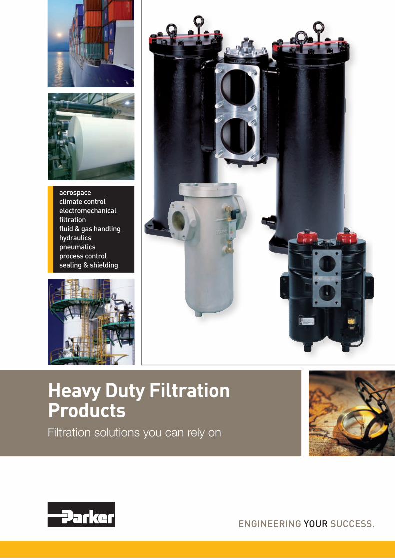
Heavy Duty Filtration ProductsFiltration solutions you can rely on

2 3www.parker.comwww.parker.com
• Consistent quality• Technical innovation• Premier customer service
Parkers technical resources provide the correct filtration technologies that conform to your requirements. That’s why thousands of manufacturers and equipment users around the world rely on Parker Filtration products and people.
Worldwide Salesand Service
Parker Filtration’s global reputation as a reliablesupplier of superior filtration products is the resultof a focused and integrated development andmanufacturing system.
Parker Filtration consolidates quality filtrationproducts, manufactured by process filtration, airand gas filtration and separation, fuel conditioningand filtration, hydraulic and lubrication filtration,fluid power products and fluid condition monitoringequipment into one broad-based range thatcovers many markets and most applications, as detailed here.
Hydraulic, Lubrication &Coolant Filtration
High-performance filtrationsystems for productionmachinery in industrial, mobileand military/marine applications.
Compressed Air &Gas Filtration
Complete line of compressedair/gas filtration products;coalescing, particulate andadsorption filters in manyapplications in many industries.
Process & ChemicalFluid Filtration
Liquid filtration systems forbeverage, chemical and foodprocessing; cosmetic, paint,water treatment; photo-processing; and micro-chipfabrication.
Racor Fuel Conditioning& Filtration
Parker air, fuel and oil filtrationsystems provide qualityprotection for engines operatingin any environment, anywherein the world.
System ContaminationMonitoring
On-line dynamic particleanalysis, off-line bottlesampling and fluid analysis andmeasurement of water contentpolluting the oil in a system. All important and achievable,cost-effective solutions availableto equipment manufacturers and end users alike.
Photo courtesy of GLASBAU HAHN.
DEGREE OF FILTRATION
Average filtration beta ratio ß (ISO 16889) particle size µm (c)
Element type codeßx=2 ßx=10 ßx=75 ßx=100 ßx=200 ßx=1000
% Efficiency, based on the above beta ratio (ßx)
50.0 % 90.0 % 98.7 % 99.0 % 99.5 % 99.9 %
N/A N/A N/A N/A N/A 4.5 Q002/QE02, 02Q/02QL
N/A N/A 4.5 5 6 7 Q005/QE05, 05Q/05QL
N/A 6 8.5 9 10 12 Q010/QE10, 10Q/10QL
6 11 17 18 20 22 Q020/QE20, 20Q/20QL
Parker glass fiber filtration media Microglass III and environmentally friendly Ecoglass III are designed to provide maximum protection for your equipment.
The filters are available with stainless steel metal mesh elements, which are also cleanable. In most cases the standard filtration ratings are 35 µm(abs) and 60 µm(abs). Other ratings are available by request.
Heavy Duty Filtration ProductsContents
FF1087 Series ............................................................... 4-7
GA Series .................................................................... 8-13
BGAH Series ............................................................. 14-19
BGLS Series .............................................................. 20-23
FF1040 Series ........................................................... 24-27
Eco 130 Series .......................................................... 28-35
FF2146 ...................................................................... 36-39
FF2089 ...................................................................... 40-43
FF2110 Series ........................................................... 44-47
FF2050 Series ........................................................... 48-51
FF2035 Series ........................................................... 52-55
FF2060 Series ........................................................... 56-59
FF2070 Series ........................................................... 60-63
FMU Indicators ........................................................ 64-67
Parker Racor products ............................................. 68-69
Marine PARFIT ........................................................ 70-72
Heavy duty filtration solutions as you wishParker can provide correct filtration solution for multitude of fuel, gas, hydraulic oil and lubrication systems. Wide selection of low and medium pressure multi-purpose filters combined to several different filter elements – environmentally sound choices too – allow highly customizable solutions. Duplex filters and ability to bank multiple filters together enables continuous filtration during element changes. Parker heavy duty solutions for clean fluids and peace of mind.
The following table shows average efficiencies of the filter elements and the corresponding filtration rating codes. Because of historical reasons the codes repre-senting filtration ratings may vary slightly.

5www.parker.com
In-line peace of mindThree different housing sizes and several media options allow wide range of applications. Cast iron housing is operable up to 40 bars. Pre-filtration with magnets is available as well as several connection options.
Applications:
• Industrialgearboxes• Heavyfueloilfilterfordieselengines
• Suctionfilterforfuelsystems• Mediumpressurehydraulicfilter
FF1087 SeriesMedium Pressure Filters
Contact Information:ParkerHannifinCorporationHydraulic Filter Division [email protected]
www.parker.com
Type Weight A D F G H J K L M N P R S T U
1087 5.5kg 150 G1 170 27 83 125 45 275 11 108 71 118 159 32 200
1088 12kg 190 G1½ 230 38 112 170 64 350 13 148 106 139 180 55 210
1089 15kg 260 G1½ 230 38 112 170 64 420 13 148 106 139 180 55 210
1089-DT80 24kg 260 80 310 - 112 - 200 420 - 148 106 139 180 55 210
Specification
Assembly:In-line filterMaximum operating pressure:40 barNominal flow rate (30cSt):350 l/min (21 m3/h)Connections:Threads G1 for FF1087 and G1½ for FF1088 and FF1089. FF1089 is available also with flanges DN80/PN16.Seal material:Fluoroelastomer* or optionally nitrileOperating temperature:-20°C...+100°C, for other temperatures consult Parker Filtration.Housing material:Cast ironWeight:See dimensions table
Magnet pack:Available as optionBypass valve:Standard opening pressure 1.6 bar, optionally with blocked bypassIndicator options:Visual, electrical or electronic indicator requires an indicator block. For details see indicator options table in product description page. Filtration materials: •GlassfiberMicroglassIII •CleanablemetalmeshFluid compatibility:Suitable for use with regular hydraulic and lubrication oils and fuel oils. For other fluids consult Parker Filtra-tion.
* Fluoroelastomers are available under various registered trademarks, including Viton (a registered trademark of DuPont) and Fluorel (a registered trademark of 3M).
6www.parker.com
7www.parker.com
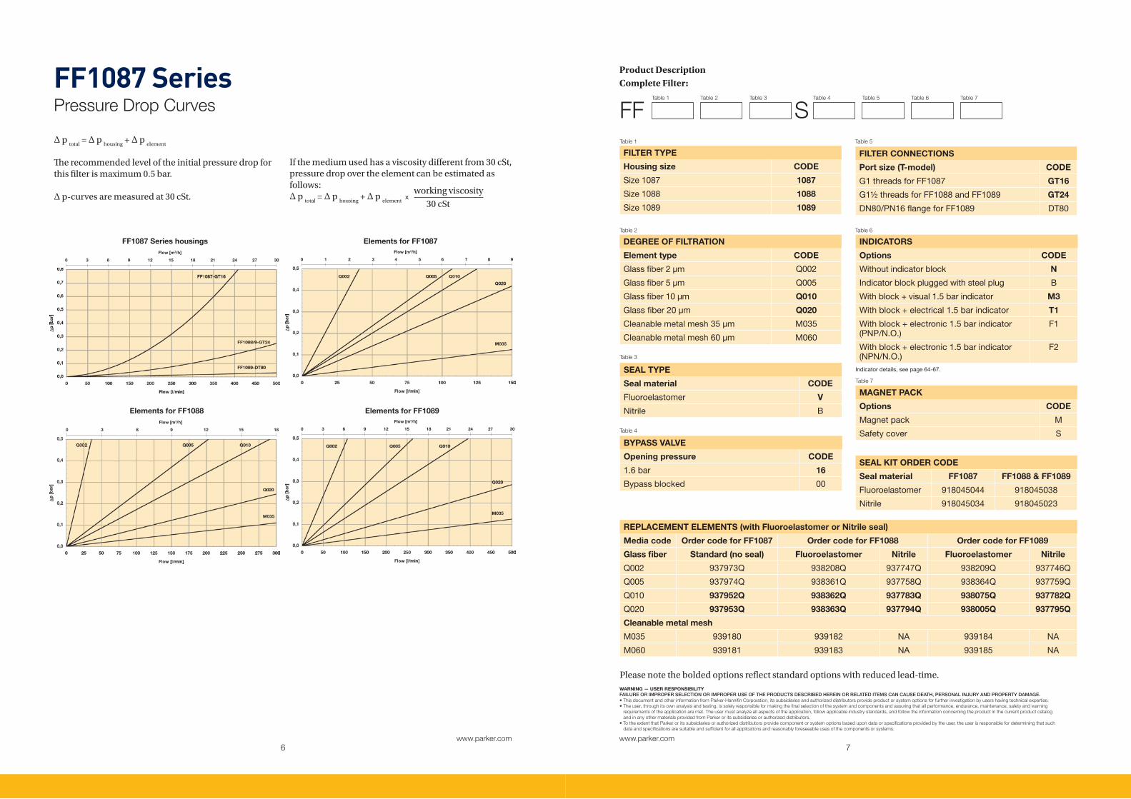
FF1087 SeriesPressure Drop Curves
WARNING — USER RESPONSIBILITYFAILURE OR IMPROPER SELECTION OR IMPROPER USE OF THE PRODUCTS DESCRIBED HEREIN OR RELATED ITEMS CAN CAUSE DEATH, PERSONAL INJURY AND PROPERTY DAMAGE.• This document and other information from Parker-Hannifin Corporation, its subsidiaries and authorized distributors provide product or system options for further investigation by users having technical expertise. • The user, through its own analysis and testing, is solely responsible for making the final selection of the system and components and assuring that all performance, endurance, maintenance, safety and warning requirements of the application are met. The user must analyze all aspects of the application, follow applicable industry standards, and follow the information concerning the product in the current product catalog and in any other materials provided from Parker or its subsidiaries or authorized distributors. • To the extent that Parker or its subsidiaries or authorized distributors provide component or system options based upon data or specifications provided by the user, the user is responsible for determining that such data and specifications are suitable and sufficient for all applications and reasonably foreseeable uses of the components or systems.
∆ p total
= ∆ p housing
+ ∆ p element
The recommended level of the initial pressure drop for this filter is maximum 0.5 bar.
∆ p-curves are measured at 30 cSt.
FILTER TYPE
Housing size CODE
Size1087 1087
Size1088 1088
Size1089 1089
Table 1
DEGREE OF FILTRATION
Element type CODE
Glassfiber2µm Q002
Glassfiber5µm Q005
Glassfiber10µm Q010
Glassfiber20µm Q020
Cleanablemetalmesh35µm M035
Cleanablemetalmesh60µm M060
Table 2
SEAL TYPE
Seal material CODE
Fluoroelastomer V
Nitrile B
Table 3
BYPASS VALVE
Opening pressure CODE
1.6bar 16
Bypassblocked 00
Table 4
FILTER CONNECTIONS
Port size (T-model) CODE
G1threadsforFF1087 GT16
G1½threadsforFF1088andFF1089 GT24
DN80/PN16flangeforFF1089 DT80
Table 5
MAGNET PACK
Options CODE
Magnetpack M
Safetycover S
Table 6
Product DescriptionComplete Filter:
FF S Table 1 Table 2 Table 3 Table 4 Table 5 Table 6 Table 7
FF1087 Series housingsFlow [m3/h]
0 3 6 9 12 15 18 21 24 27 30
Elements for FF1087Flow [m3/h]
0 1 2 3 4 5 6 7 8 9
INDICATORS
Options CODE
Withoutindicatorblock N
Indicatorblockpluggedwithsteelplug B
Withblock+visual1.5barindicator M3
Withblock+electrical1.5barindicator T1
Withblock+electronic1.5barindicator(PNP/N.O.)
F1
Withblock+electronic1.5barindicator(NPN/N.O.)
F2
Table 7
Indicatordetails,seepage64-67.
REPLACEMENT ELEMENTS (with Fluoroelastomer or Nitrile seal)
Media code Order code for FF1087 Order code for FF1088 Order code for FF1089
Glass fiber Standard (no seal) Fluoroelastomer Nitrile Fluoroelastomer Nitrile
Q002 937973Q 938208Q 937747Q 938209Q 937746Q
Q005 937974Q 938361Q 937758Q 938364Q 937759Q
Q010 937952Q 938362Q 937783Q 938075Q 937782Q
Q020 937953Q 938363Q 937794Q 938005Q 937795Q
Cleanable metal mesh
M035 939180 939182 NA 939184 NA
M060 939181 939183 NA 939185 NA
SEAL KIT ORDER CODE
Seal material FF1087 FF1088 & FF1089
Fluoroelastomer 918045044 918045038
Nitrile 918045034 918045023
Please note the bolded options reflect standard options with reduced lead-time.
Elements for FF1088Flow [m3/h]
0 3 6 9 12 15 18
Elements for FF1089Flow [m3/h]
0 3 6 9 12 15 18 21 24 27 30
If the medium used has a viscosity different from 30 cSt, pressure drop over the element can be estimated as follows: ∆ p
total = ∆ p
housing + ∆ p
element x
working viscosity
30 cSt

9www.parker.com
GA SeriesMedium Pressure Filters
Specification
Assembly: In-line filterMaximum operating pressure:30 barNominal flow rate (30 cSt):230 l/min (13.8 m3/h)Connections: Threaded BSP portsSeal material: Nitrile, optionally Fluoroelastomer* or NeopreneOperating temperature: -20°C...+100°C, for other temperatures consult Parker Filtration.Housing material:AluminiumWeight:See dimensions tableBypass setting:Opening pressure standard 1.5 bar, optionally 0.8 bar, 2.0 bar or blocked bypass
Filtration materials: •Ecoglass for LEIF® element with reusable metal element sleeve. LEIF® contributes to ISO14001. •GlassfiberMicroglassIII •Resinimpregnatedcellulosepaper10μmnominal •CleanablemetalmeshMagnetic pack:StandardDifferential pressure indicators:Visual or Visual-electrical indicatorSetting 1.2 bar (for 2.0 bar and 1.5 bar bypass) or 0.7 bar (for 0.8 bar bypass)Fluid compatibility:Suitable for use with regular hydraulic and lubrication oils. For other fluids consult Parker Filtration.
* Fluoroelastomers are available under various registered trademarks, including Viton (a registered trademark of DuPont) and Fluorel (a registered trademark of 3M).
Contamination-proof and customizable filter solutionDesigned for various applications. In-out filter principle means there is no possibility for contaminated leak back into the system. Supplied with magnetic pre-filtration. Customizable for filter coolants thus ideal for metal cutting equipment. Visual or electronic differential pressure indicators and environmentally friendly filtration elements available.
Applications:
• Gearboxes• Bypassfiltration• Stonecrushers• Lubeoilsystems• Metalcuttingequipment
Contact Information:ParkerHannifinCorporationHydraulic Filter Division [email protected]
www.parker.com
Type A B C D E F G H K L M N P S T U V Kg
BSPISO228 SAE
GA 1-30 150 106 32 G¾ 12 70 180 3 50 24 95 9 44 20 28 143 86 63 2.1
GA 1-60 160 106 32 G1 16 70 235 18 50 24 95 9 54 20 29 194 86 63 2.6
GA 1-90 160 106 32 G1 16 70 275 29 50 24 95 9 54 20 29 238 86 63 3.2
GA 1-120 160 106 32 G1¼ 20 70 325 46 50 24 95 9 64 20 29 288 86 63 4.0
GA 2-170 230 150 55 G1½ 24 105 390 35 75 37 140 12 72 25 43 338 110 88 7.9
GA 2-230 230 150 55 G1½ 24 105 460 58 75 37 140 12 72 25 43 408 110 88 9.0

10www.parker.com
11www.parker.com
Visual Indicator - Manifold connected to filter housing
Code(0.7barsetting) FMUD5BBAXXXL
Code(1.2barsetting) FMUD5EBAXXXL
Electrical Indicator - Manifold connected to filter housing
Code(0.7barsettingandNOtypeswitch) FMUE5BBAXXXL
Code(1.2barsettingandNOtypeswitch) FMUE5EBAXXXL
Electricrating 120Vac/12VAor100Vdc/10W
Electricalconnection AMPterminal6.3.x0.8withpluggedcablegland
Protection IP65
Switchtype NO(NCrequest)
GA SeriesPressure Drop Curves for Elements
GA2-230 elements (Length 7)
GA SeriesPressure Drop Curves for Housing
∆ p total
= ∆ p housing
+ ∆ p element
The recommended level of the initial pressure drop for this filter is maximum 0.5 bar.
∆ p-curves are measured at 30 cSt.
If the medium used has a viscosity different from 30 cSt, pressure drop over the element can be estimated as follows: ∆ p
total = ∆ p
housing + ∆ p
element x
working viscosity
30 cSt
GA1 housings GA2-170/230 housingsFlow [m3/h]
0 1 2 3 4 5 6 7 8 9
Flow [m3/h]
0 3 6 9 12 15 18
GA1-30 elements (Length 0)Flow [m3/h]
0 1 2 3
GA1-60 elements (Length 2)Flow [m3/h]
0 1 2 3 4 5 6
GA1-90 elements (Length 3)Flow [m3/h]
0 3 6 9
GA1-120 elements (Length 4)Flow [m3/h]
0 3 6 9 12
GA2-170 elements (Length 6)Flow [m3/h]
0 3 6 9 12 15
Flow [m3/h]
0 3 6 9 12 15 18

12www.parker.com
13www.parker.com
WARNING — USER RESPONSIBILITYFAILURE OR IMPROPER SELECTION OR IMPROPER USE OF THE PRODUCTS DESCRIBED HEREIN OR RELATED ITEMS CAN CAUSE DEATH, PERSONAL INJURY AND PROPERTY DAMAGE.• This document and other information from Parker-Hannifin Corporation, its subsidiaries and authorized distributors provide product or system options for further investigation by users having technical expertise. • The user, through its own analysis and testing, is solely responsible for making the final selection of the system and components and assuring that all performance, endurance, maintenance, safety and warning requirements of the application are met. The user must analyze all aspects of the application, follow applicable industry standards, and follow the information concerning the product in the current product catalog and in any other materials provided from Parker or its subsidiaries or authorized distributors. • To the extent that Parker or its subsidiaries or authorized distributors provide component or system options based upon data or specifications provided by the user, the user is responsible for determining that such data and specifications are suitable and sufficient for all applications and reasonably foreseeable uses of the components or systems.
Product DescriptionComplete Filter:
Table 1 Table 2 Table 3 Table 4 Table 5 Table 6 Table 7
FILTER TYPE
Housing CODE
GA 1-30 0
GA 1-60 2
GA 1-90 3
GA 1-120 4
GA 2-170 6
GA 2-230 7
Table 1
SEAL TYPE
Seal material CODE
Nitrile B
Neoprene N
Fluoroelastomer V
Table 3
INDICATORS
Options CODE
Visualindicatormountedonrightside D1
Visualindicatormountedonleftside D2
Visual-electricalindicatormountedonrightside
E1
Visual-electricalindicatormountedonleftside
E2
Noindicator,indicatorportsnotmachined N
Noindicator,indicatorportsR+Lplugged P2
Table 4
BYPASS VALVE
Opening pressure CODE
0.8bar B
1.5bar E
2.0bar H
Bypassblocked X
Table 5
FILTER CONNECTIONS
Port size CODE
G¾”(GAlength0) G12
G1”(GAlength2and3) G16
G1¼”(GAlength4) G20
G1½”(GAlength6and7) G24
Table 6
OPTIONS
CODE
Standard 1
Nomagnets 5
Table 7
CONVENTIONAL TYPE REPLACEMENT ELEMENTS WITH NITRILE SEALS
Element length
Housing size
Microglass III Cellulose 10 µm (nom)
Cleanable metal mesh
40 µm02Q 05Q 10Q 20Q
0 1 - 30 937752Q 937753Q 937788Q 937789Q 937720 937821
2 1 - 60 937751Q 937754Q 937787Q 937790Q 937721 937820
3 1 - 90 937750Q 937755Q 937786Q 937791Q 937722 937819
4 1 - 120 937749Q 937756Q 937785Q 937792Q 937723 937818
6 2 - 170 937747Q 937758Q 937783Q 937794Q 937725 937816
7 2 - 230 937746Q 937759Q 937782Q 937795Q 937726 937815
LEIF® REPLACEMENT ELEMENTS
Element length
Housing size
Ecoglass III
02QL 05QL 10QL 20QL
0 1 - 30 937822Q 937885Q 937884Q 937883Q
2 1 - 60 937823Q 937880Q 937881Q 937882Q
3 1 - 90 937824Q 937879Q 937878Q 937877Q
4 1 - 120 937825Q 937850Q 937851Q 937876Q
6 2 - 170 937827Q 937848Q 937853Q 937874Q
7 2 - 230 937828Q 937847Q 937854Q 937873Q
GA SeriesMedium Pressure Filters
GA
DEGREE OF FILTRATION
Glass fiber CODEMicroglassIIILEIF®elements
02Q 05Q 10Q 20Q
02QL 05QL 10QL 20QL
Other medias
Cellulose CODE
10µm(nom) 10C
Cleanablemetalmesh
CODE
40µm 040W
Table 2

15www.parker.com
BGAH SeriesMedium Pressure Filters
In-line solution for a straight pipelinePre-filtration by magnet column and a full-flow bypass with low hysteresis. Contamination-proof in-out filter principle. In- and outlet configuration allows integration in a straight pipeline. Nominal flow rate up to 500 l/min. Highly customizable for different applications.
Applications:
• Industrialgearboxes• Windturbines• Stonecrushers• Bypassandoff-linefiltration
Contact Information:ParkerHannifinCorporationHydraulic Filter Division [email protected]
www.parker.com
Specification
Assembly:In-line filterMaximum operating pressure:25 barNominal flow rate (30 cSt):500 l/min (30 m3/h)Connections:Flanges SAE 3” 3000-MSeal material:Nitrile, optionally Fluoroelastomer* or NeopreneOperating temperature:-20°C...+100°C, for other temperatures consult Parker Filtration.Housing material:AluminiumWeight:BGAH 3-400: 21 kgBGAH 3-500: 28 kgBypass setting:Opening pressure standard 1.5 bar, optionally 0.8 bar, 2.0 bar or blocked bypass
Filtration materials: •EcoglassforLEIF®elementwithreusablemetal element sleeve. LEIF® contributes to ISO14001. •GlassfiberMicroglassIII •Resinimpregnatedcellulosepaper10μmnominal •CleanablemetalmeshMagnetic pack:StandardDifferential pressure indicators:Visual or Visual-electrical indicatorSetting 1.2 bar (for 2.0 bar and 1.5 bar bypass) or 0.7 bar (for 0.8 bar bypass)Fluid compatibility:Suitable for use with regular hydraulic and lubrication oils. For other fluids consult Parker Filtration.
* Fluoroelastomers are available under various registered trademarks, including Viton (a registered trademark of DuPont) and Fluorel (a registered trademark of 3M).
Type A B
BGAH3-400 550 400
BGAH3-500 740 590

16www.parker.com
17www.parker.com
Visual Indicator - Mounted with couplings to filter housing
Code(0.7barsetting) FMUD6BBAXXXL
Code(1.2barsetting) FMUD6EBAXXXL
Electrical Indicator - Mounted with couplings to filter housing
Code(0.7barsettingandNOtypeswitch) FMUEBBBAXXXL
Code(1.2barsettingandNOtypeswitch) FMUEBEBAXXXL
Electricrating 120Vac/12VAor100Vdc/10W
Electricalconnection AMPterminal6.3.x0.8withpluggedcablegland
Protection IP65
Switchtype NO(NConrequest)
BGAH SeriesPressure Drop Curves
∆ p total
= ∆ p housing
+ ∆ p element
The recommended level of the initial pressure drop for this filter is maximum 0.5 bar.
∆ p-curves are measured at 30 cSt.
If the medium used has a viscosity different from 30 cSt, pressure drop over the element can be estimated as follows: ∆ p
total = ∆ p
housing + ∆ p
element x
working viscosity
30 cSt
BGAH housing
Flow [m3/h]
0 3 6 9 12 15 18 21 24 27 30 33 36
BGAH 3-400 elements (Length 11)
Flow [m3/h]
0 3 6 9 12 15 18 21 24 27 30 33 36
BGAH 3-500 elements (Length 12)
Flow [m3/h]
0 3 6 9 12 15 18 21 24 27 30 33 36

18www.parker.com
19www.parker.com
WARNING — USER RESPONSIBILITYFAILURE OR IMPROPER SELECTION OR IMPROPER USE OF THE PRODUCTS DESCRIBED HEREIN OR RELATED ITEMS CAN CAUSE DEATH, PERSONAL INJURY AND PROPERTY DAMAGE.• This document and other information from Parker-Hannifin Corporation, its subsidiaries and authorized distributors provide product or system options for further investigation by users having technical expertise. • The user, through its own analysis and testing, is solely responsible for making the final selection of the system and components and assuring that all performance, endurance, maintenance, safety and warning requirements of the application are met. The user must analyze all aspects of the application, follow applicable industry standards, and follow the information concerning the product in the current product catalog and in any other materials provided from Parker or its subsidiaries or authorized distributors. • To the extent that Parker or its subsidiaries or authorized distributors provide component or system options based upon data or specifications provided by the user, the user is responsible for determining that such data and specifications are suitable and sufficient for all applications and reasonably foreseeable uses of the components or systems.
FILTER TYPE
Housing CODE
BGAH3-400 11
BGAH3-500 12
Table 1
SEAL TYPE
Seal material CODE
Nitrile B
Fluoroelastomer V
Neoprene N
Table 3
BYPASS VALVE
Opening pressure CODE
0.8bar B
1.5bar E
2.0bar H
Bypassblocked X
Table 5
OPTIONS
CODE
Standard 1
Nomagnets 5
Table 6
CONVENTIONAL TYPE REPLACEMENT ELEMENTS WITH NITRILE SEALS
Element length
Housing size
Microglass III Cellulose 10 µm (nom)
Cleanable metal mesh
40 µm02Q 05Q 10Q 20Q
11 3 - 400 937742Q 937763Q 937778Q 937799Q 937728 937813
12 3 - 500 937741Q 937764Q 937777Q 937800Q 937729 937812
LEIF® REPLACEMENT ELEMENTS
Element length
Housing size
Ecoglass III
02QL 05QL 10QL 20QL
11 3 - 400 937832Q 937843Q 937858Q 937869Q
12 3 - 500 937833Q 937842Q 937859Q 937868Q
BGAH SeriesMedium Pressure Filters
Product DescriptionComplete Filter:
Table 1 Table 2 Table 3 Table 4 Table 5 Table 6
BGAH R48
DEGREE OF FILTRATION
Glass fiber CODEMicroglassIIILEIF®elements
02Q 05Q 10Q 20Q
02QL 05QL 10QL 20QL
Other medias
Cellulose CODE
10µm(nom) 10C
Cleanablemetalmesh
CODE
40µm 040W
Table 2
INDICATORS
Options CODE
Visualindicatormountedonrightside D6
Visualindicatormountedonleftside D7
Visual-electricalindicatormountedonrightside
E7
Visual-electricalindicatormountedonleftside
E8
Noindicator,indicatorportsnotmachined N
Noindicator,indicatorportsR+Lplugged P2
Table 4

21www.parker.com
BGLS SeriesLow Pressure Filters
Heavy duty in-line filter solutionUpper housing aluminium and lower housing steel allows low weight combined to high capacity. Magnetic pre-filtration and nominal flow up to 2000 l/min.
Applications:
• Lubricationsystems• Windturbines• Hydraulicpresses• Largeindustrialgearboxes
Contact Information:ParkerHannifinCorporationHydraulic Filter Division [email protected]
www.parker.com
Specification
Assembly:In-line filterMaximum operating pressure:10 barNominal flow rate (30 cSt):2000 l/min (120 m3/h)Connections:Flanges SAE 3” 3000-MSeal material:Nitrile, optionally Fluoroelastomer*Operating temperature:-20°C...+100°C, for other temperatures consult Parker Filtration.Housing material:Upper housing aluminium, lower housing steelWeight:BGLS 4-1000: 56 kgBGLS 4-1500: 65 kgBGLS 4-2000: 75 kg
Bypass setting:Opening pressure standard 1.5 barFiltration materials: •EcoglassforLEIF®elementwithreusablemetal element sleeve. LEIF® contributes to ISO14001. •GlassfiberMicroglassIII •Resinimpregnatedcellulosepaper10μmnominal •CleanablemetalmeshMagnetic pack:StandardDifferential pressure indicators:Visual or Visual-electrical indicatorSetting 1.2 barFluid compatibility:Suitable for use with regular hydraulic and lubrication oils. For other fluids consult Parker Filtration.
* Fluoroelastomers are available under various registered trademarks, including Viton (a registered trademark of DuPont) and Fluorel (a registered trademark of 3M).
Type H L F
1000 975 635 735
1500 1255 915 1015
2000 1520 1180 1280
Indicatordetails,seepage16.

22www.parker.com
23www.parker.com
WARNING — USER RESPONSIBILITYFAILURE OR IMPROPER SELECTION OR IMPROPER USE OF THE PRODUCTS DESCRIBED HEREIN OR RELATED ITEMS CAN CAUSE DEATH, PERSONAL INJURY AND PROPERTY DAMAGE.• This document and other information from Parker-Hannifin Corporation, its subsidiaries and authorized distributors provide product or system options for further investigation by users having technical expertise. • The user, through its own analysis and testing, is solely responsible for making the final selection of the system and components and assuring that all performance, endurance, maintenance, safety and warning requirements of the application are met. The user must analyze all aspects of the application, follow applicable industry standards, and follow the information concerning the product in the current product catalog and in any other materials provided from Parker or its subsidiaries or authorized distributors. • To the extent that Parker or its subsidiaries or authorized distributors provide component or system options based upon data or specifications provided by the user, the user is responsible for determining that such data and specifications are suitable and sufficient for all applications and reasonably foreseeable uses of the components or systems.
HOUSING SIZE
CODE
4 - 1000 15
4 - 1500 16
4 - 2000 17
Table 1
SEAL MATERIAL
CODE
Nitrile B
Fluoroelastomer V
Table 3
OPTIONS
CODE
Standard 1
Nomagnets 5
Table 6
DEGREE OF FILTRATION
Glass fiber CODEMicroglassIIILEIF®elements
02Q 05Q 10Q 20Q
02QL 05QL 10QL 20QL
Other medias
Cellulose CODE
10µm(nom) 10C
Cleanablemetalmesh
CODE
40µm 040W
Table 2
BGLS Series Pressure Drop Curves
OUTLET POSITION
CODE
Front(0degrees) F
Right(90degrees) R
Back(180degrees) B
Left(270degrees) L
Table 5
Lookingfrominletconnection.
∆ p total
= ∆ p housing
+ ∆ p element
The recommended level of the initial pressure drop for this filter is maximum 0.5 bar.
∆ p-curves are measured at 30 cSt.
If the medium used has a viscosity different from 30 cSt, pressure drop over the element can be estimated as follows: ∆ p
total = ∆ p
housing + ∆ p
element x
working viscosity
30 cSt
BGLS housing
Flow [m3/h]
0 12 24 36 48 60 72 84 96 108 120
BGLS 4-1500 elements (Length 16)
Flow [m3/h]
0 6 12 18 24 30 36 42 48 54 60 72 78 78 84 90
BGLS 4-1000 elements (Length 15)
Flow [m3/h]
0 6 12 18 24 30 36 42 48 54 60
Product DescriptionComplete Filter:
BGLS ER48 Table 1 Table 2 Table 3 Table 4 Table 5 Table 6
BGLS 4-2000 elements (Length 17)
Flow [m3/h]
0 12 24 36 48 60 72 84 96 108 120
CONVENTIONAL TYPE REPLACEMENT ELEMENTS WITH NITRILE SEALS
Element length
Housing size
Microglass III Cellulose 10 µm (nom)
Cleanable metal mesh
40 µm02Q 05Q 10Q 20Q
15 4 - 1000 937738Q 937767Q 937774Q 937803Q 937732 937809
16 4 - 1500 937737Q 937768Q 937773Q 937804Q 937733 937808
17 4 - 2000 937736Q 937769Q 937772Q 937805Q 937734 937807
LEIF® REPLACEMENT ELEMENTS
Element length
Housing size
Ecoglass III
02QL 05QL 10QL 20QL
15 4 - 1000 937836Q 937839Q 937862Q 937865Q
16 4 - 1500 937837Q 937838Q 937863Q 937864Q
17 4 - 2000 NA NA NA NA
Indicatorsetting1.2bar.
INDICATORS
Options CODE
Visualindicatormountedonrightside D1
Visualindicatormountedonleftside D2
Visual-electricalindicatormountedonrightside
E1
Visual-electricalindicatormountedonleftside
E2
Noindicator,indicatorportsnotmachined N
Noindicator,indicatorportsR+Lplugged P2
Table 4

25www.parker.com
FF1040 Series Low Pressure Filters
Multi-purpose filter for gas and high flow fluid systemsStrong welded steel construction housing features DN80 or DN100 connections. Several media options including PED 3 classified versions for gas applications. As options available safety filter to secure filtration even in by pass situations, and differential pressure indicator for accurate operation control.
Applications:
• Lubricatingoilfilterforindustrialsystems
• Gasfinefilterforcombustionengines
• Fueloilfilterforhighflowsystems
• Largeonlinelow-pressurefilterforhydraulicsystems
Contact Information:ParkerHannifinCorporationHydraulic Filter Division [email protected]
www.parker.com
Specification
Assembly:In-line filterMaximum operating pressure:10 barNominal flow rate (30 cSt):1400 l/min (84 m3/h)Connections:Flanges DN80/PN16 or DN100/PN16Seal material:Fluoroelastomer*Operating temperature:-20°C...+120°C, or other temperatures consult Parker Filtration.Housing material:Steel or stainless steelWeight:100 kgBypass valve:Standard without bypass. Optionally opening pressure 2.0 bar.
Filtration materials: •GlassfiberMicroglassIII •Resinimpregnatedcellulosepaper15μmnominal •CleanablemetalmeshIndicator options:Visual, electrical or electronic indicator requires an indicator block. For details see indicator options table in product description page.Fluid compatibility:Suitable for use with regular hydraulic and lubrication oils and fuel oils. For heavy fuel oil applications, please specify option P2 (see table 5 in product description) which ensures that filters are delivered with documen-tation according PED 97/23/EC category II. Respective-ly for combustible gas applications, specify option P3 for PED category III. For other fluids consult Parker Fil-tration.
* Fluoroelastomers are available under various registered trademarks, including Viton (a registered trademark of DuPont) and Fluorel (a registered trademark of 3M).
Type A B C D E F
DN80/PN16 753 160 153 932 868 440
DN100/PN16 786 186 140 978 914 460

26www.parker.com
27www.parker.com
WARNING — USER RESPONSIBILITYFAILURE OR IMPROPER SELECTION OR IMPROPER USE OF THE PRODUCTS DESCRIBED HEREIN OR RELATED ITEMS CAN CAUSE DEATH, PERSONAL INJURY AND PROPERTY DAMAGE.• This document and other information from Parker-Hannifin Corporation, its subsidiaries and authorized distributors provide product or system options for further investigation by users having technical expertise. • The user, through its own analysis and testing, is solely responsible for making the final selection of the system and components and assuring that all performance, endurance, maintenance, safety and warning requirements of the application are met. The user must analyze all aspects of the application, follow applicable industry standards, and follow the information concerning the product in the current product catalog and in any other materials provided from Parker or its subsidiaries or authorized distributors. • To the extent that Parker or its subsidiaries or authorized distributors provide component or system options based upon data or specifications provided by the user, the user is responsible for determining that such data and specifications are suitable and sufficient for all applications and reasonably foreseeable uses of the components or systems.
FF1040 seriesPressure Drop Curves
∆ p total
= ∆ p housing
+ ∆ p element
The recommended level of the initial pressure drop for this filter is maximum 0.5 bar.
∆ p-curves are measured at 30 cSt.
If the medium used has a viscosity different from 30 cSt, pressure drop over the element can be estimated as follows: ∆ p
total = ∆ p
housing + ∆ p
element x
working viscosity
30 cStTable 1
DEGREE OF FILTRATION
Glass fiber CODEMicroglassIII 005Q 010Q 020Q
Other medias
Cellulose CODE
15µm(nom) N015
Cleanablemetalmesh
CODE
35µm M035
HOUSING MATERIAL
CODE
Steel S
Stainlesssteel R
Table 2
Product DescriptionComplete Filter:
Element:
FF1040 V
FC2040 BS
Table 1
Table 1
Table 2 Table 3 Table 4 Table 5 Table 6
BYPASS VALVE
Opening pressure CODE
2.0bar 20
Bypassvalveblocked 00
Table 3
FILTER CONNECTIONS
CODE
DN80/PN16,connectionsonoppositesides DT80
DN100/PN16,connectionsonoppositesides DT100
DN80/PN16,connectionsonsameside DC80
Table 4
INDICATORS
Options CODE
Withoutindicatorblock N
Indicatorblockpluggedwithsteelplug B
Withblock+visual1.5barindicator M3
Withblock+electrical1.5barindicator T1
Withblock+electronic1.5barindicator(PNP/N.O.)
F1
Withblock+electronic1.5barindicator(NPN/N.O.)
F2
Table 6
Indicatordetails,seepage64-67.
OPTIONS
CODE
PEDclass3 P3
Horizontalmounting H
Mountingbrackets B
With60µmsafetyelement S
Table 5
Ifseveraloptionsareselected,pleaseaddthecodesinorderlistedabove.
FF1040 DN80/PN16 housing
Flow [m3/h]
0 12 24 36 48 60 72 84 96 108 120
FF1040 element pack (2 pcs)
Flow [m3/h]
0 12 24 36 48 60 72 84 96 108 120
29www.parker.com
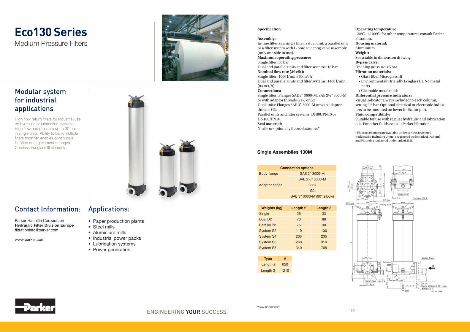
Eco130 SeriesMedium Pressure Filters
Modular system for industrial applicationsHigh flow return filters for industrial use on hydraulic or lubrication systems. High flow and pressure up to 30 bar in single units. Ability to bank multiple filters together enables continuous filtration during element changes. Coreless Ecoglass III elements.
Applications:
• Paperproductionplants• Steelmills• Aluminiummills• Industrialpowerpacks• Lubricationsystems• Powergeneration
Contact Information:ParkerHannifinCorporationHydraulic Filter Division [email protected]
www.parker.com
Specification
Assembly:In-line filter as a single filter, a dual unit, a parallel unit or a filter system with L-bore selecting valve assembly (only one side in use).Maximum operating pressure:Single filter: 30 barDual and parallel units and filter systems: 16 barNominal flow rate (30 cSt):Single filter: 1000 l/min (60 m3/h)Dual and parallel units and filter systems: 1400 l/min (84 m3/h)Connections:Single filter: Flanges SAE 2” 3000-M, SAE 2½” 3000-M or with adaptor threads G1½ or G2.Dual units: Flanges SAE 3” 3000-M or with adaptor threads G2.Parallel units and filter systems: DN80/PN16 or DN100/PN16. Seal material:Nitrile or optionally fluoroelastomer*
Operating temperature:-20°C...+100°C, for other temperatures consult Parker Filtration.Housing material:AluminiumWeight:See a table in dimension drawingBypass valve:Opening pressure 3.5 barFiltration materials: •GlassfiberMicroglassIII •EnvironmentallyfriendlyEcoglassIII.Nometal parts. •CleanablemetalmeshDifferential pressure indicators:Visual indicator always included to each column, setting 2.5 bar. Optional electrical or electronic indica-tors to be mounted on lower indicator port.Fluid compatibility:Suitable for use with regular hydraulic and lubrication oils. For other fluids consult Parker Filtration.
* Fluoroelastomers are available under various registered trademarks, including Viton (a registered trademark of DuPont) and Fluorel (a registered trademark of 3M).
Connection options
Bodyflange SAE2”3000-M
SAE2½”3000-M
Adaptorflange G1½
G2
SAE3”3000-M(90°elbow)
Single Assemblies 130M
Weights (kg) Length 2 Length 3
Single 25 33
DualD2 70 86
ParallelP2 75 90
SystemS2 110 130
SystemS4 205 235
SystemS6 260 310
SystemS8 340 705
Type A
Length2 650
Length3 1210

30www.parker.com
31www.parker.com
Eco130 SeriesMedium Pressure Filters
Dual System 130D 130S System 1 + 1 units
T-model
Parallel System 130N 130S System 2 + 2 units
T-model
Connection options
Bodyflange SAE3”3000-M
Adaptorflangethread G2
Type A
Length2 780
Length3 1340
Type A
Length2 780
Length3 1340
Type A
Length2 780
Length3 1340
Type A
Length2 780
Length3 1340
90°
90°

32www.parker.com
33www.parker.com
130S System 3 + 3 units
T-model
130S System
L-model
130S System 4 + 4 units
T-model
130S System
L-model
90°
90°
Type A
Length2 780
Length3 1340
Type A
Length2 780
Length3 1340
Type A
Length2 780
Length3 1340
Type A
Length2 780
Length3 1340
90°
90°

34www.parker.com
35www.parker.com
WARNING — USER RESPONSIBILITYFAILURE OR IMPROPER SELECTION OR IMPROPER USE OF THE PRODUCTS DESCRIBED HEREIN OR RELATED ITEMS CAN CAUSE DEATH, PERSONAL INJURY AND PROPERTY DAMAGE.• This document and other information from Parker-Hannifin Corporation, its subsidiaries and authorized distributors provide product or system options for further investigation by users having technical expertise. • The user, through its own analysis and testing, is solely responsible for making the final selection of the system and components and assuring that all performance, endurance, maintenance, safety and warning requirements of the application are met. The user must analyze all aspects of the application, follow applicable industry standards, and follow the information concerning the product in the current product catalog and in any other materials provided from Parker or its subsidiaries or authorized distributors. • To the extent that Parker or its subsidiaries or authorized distributors provide component or system options based upon data or specifications provided by the user, the user is responsible for determining that such data and specifications are suitable and sufficient for all applications and reasonably foreseeable uses of the components or systems.
Table 1 Table 2 Table 3 Table 4 Table 5 Table 6 Table 7 Table 8
FILTER TYPE
Model CODE
Singleunit M
Dualunit D
Parallelunit N
System S
Table 1
FILTER TYPE
Length CODE
Length2 2
Length3 3
Table 2
SEAL TYPE
Seal material CODE
Nitrile B
Fluoroelastomer V
Table 4
BYPASS VALVE
Bypass valve Indicator CODE
3.5bar 2.5bar K
Table 6
OPTIONS
Options CODE
130M:standard 1
130D:2units 21
3units 31
130N:1+1units:L-port 21
2+2units:L-port 41
130S:1+1units:T-port 21
2+2units:T-port 41
3+3units:T-port 61
4+4units:T-port 81
1+1units:L-port 27
2+2units:L-port 47
3+3units:L-port 67
4+4units:L-port 87
Table 8
REPLACEMENT ECO-ELEMENTS WITH NITRILE SEALS
Media Length2 Length3
02QE 938721Q 938725Q
05QE 938722Q 938726Q
10QE 938723Q 938727Q
20QE 938724Q 938728Q
Eco130 SeriesPressure Drop Curves
130M single unit housings 130S3 system housings with DN100
Length 2 elements Length 3 elements
DEGREE OF FILTRATION
Element media Glass fibre
CODE
EcoglassIIIelement 02QE 05QE 10QE 20QE
Table 3
INDICATOR
CODE
Visualindicator M3
Electricalindicator T1
Electronic4LED,PNP,N.O. F1
Electronic4LED,NPN,N.O. F2
Table 5
VisualM3indicatoralwaysasstandard.Otherindicatoroptionsareadditionalandthe
indicatormustbemountedtolowerindicatorport.Indicatordetails,seepage64-67.
REPLACEMENT MICROGLASS III ELEMENTS WITH NITRILE SEALS
Media Length2 Length3
02Q 938733Q 938737Q
05Q 938734Q 938738Q
10Q 938735Q 938739Q
20Q 938736Q 938740Q
FILTER CONNECTIONS
Port size CODE 130M 130D 130N 130S
ThreadG1½ G24 S - - -
ThreadG2 G32 S x - -
SAEflange2”3000-M R32 x - - -
SAEflange2½”3000-M R40 S - - -
SAEflange3”3000-M R48 - S - -
DN80flange D80 - - S S
DN100flange D100 - - S S
Table 7
Availability:S=standardoption
x=non-standard,askforavailability
-=notavailable
∆ p total
= ∆ p housing
+ ∆ p element
The recommended level of the initial pressure drop for this filter is maximum 0.8 bar.
∆ p-curves are measured at 30 cSt.
If the medium used has a viscosity different from 30 cSt, pressure drop over the element can be estimated as follows: ∆ p
total = ∆ p
housing + ∆ p
element x
working viscosity
30 cSt
0 6 12 18 24 30 36 42 48 54 60
Flow [m3/h]
0 6 12 18 24 30 36 42 48 54 60 66 72 78 84 90 96
Flow [m3/h]
0 6 12 18 24 30 36 42 48 54 60
Flow [m3/h]
0 6 12 18 24 30 36 42 48 54 60
Flow [m3/h]
Product DescriptionComplete Filter:
130

37www.parker.com
FF2146Duplex Filters
Duplex safety for fuel, lube and hydraulic systemsDuplex operation for security and continuous flow. Several filtration media options include environmentally friendly Ecoglass III elements and allows wide selection of applications. Integrated differential pressure switch connection with shut off valve. Sturdy cast iron housing with pressure rating up to 40 bar – tested with 60 bar for secure margin. Block mounting available.
Applications:
• Dieselenginefuelsystems• Industriallubeoilsystems• Industrialmediumpressurehydraulicsystems
Contact Information:ParkerHannifinCorporationHydraulic Filter Division [email protected]
www.parker.com
Specification
Duplex filter:Change-over valve with open center position. Handle locking device for both end positions. Vent valves with secured outlets on both sides. Integrated indicator port with test connections.Maximum operating pressure: 40 bar Connections:Two sets of threads M26 x 1.5. Connections on flange are plugged with steel plug.Seal material: Fluoroelastomer*Operating temperature: -20°C...+120°C, for other temperatures consult Parker Filtration.Housing material: Cast iron (GJS)Weight: 15 kg
Nominal flow rate (30 cSt):80 l/min (4,8 m3/h)Bypass valve: Standard without bypass, optional opening pressure 3.5 barFiltration materials: •GlassfiberMicroglassIII •EnvironmentallyfriendlyEcoglassIII.Nometal parts. Ecoglass III contributes to ISO14001. •Cleanablemetallmesh •Resinimpregnatedfinecellulosepaper10µm nominalFluid compatibility:Suitable for use with regular hydraulic and lubrication oils & light fuel oils (diesel). For other fluids consult Parker Filtration.
* Fluoroelastomers are available under various registered trademarks, including Viton (a registered trademark of DuPont) and Fluorel (a registered trademark of 3M).

38www.parker.com
39www.parker.com
WARNING — USER RESPONSIBILITYFAILURE OR IMPROPER SELECTION OR IMPROPER USE OF THE PRODUCTS DESCRIBED HEREIN OR RELATED ITEMS CAN CAUSE DEATH, PERSONAL INJURY AND PROPERTY DAMAGE.• This document and other information from Parker-Hannifin Corporation, its subsidiaries and authorized distributors provide product or system options for further investigation by users having technical expertise. • The user, through its own analysis and testing, is solely responsible for making the final selection of the system and components and assuring that all performance, endurance, maintenance, safety and warning requirements of the application are met. The user must analyze all aspects of the application, follow applicable industry standards, and follow the information concerning the product in the current product catalog and in any other materials provided from Parker or its subsidiaries or authorized distributors. • To the extent that Parker or its subsidiaries or authorized distributors provide component or system options based upon data or specifications provided by the user, the user is responsible for determining that such data and specifications are suitable and sufficient for all applications and reasonably foreseeable uses of the components or systems.
Table 1 Table 2 Table 3 Table 4
DEGREE OF FILTRATION
Element type CODE
Glassfiber5µm Q005
Glassfiber10µm Q010
Glassfiber20µm Q020
Ecoglass5µm QE05
Ecoglass10µm QE10
Ecoglass20µm QE20
Cellulosepaper10µm NE10
Cleanablemetalmesh35µm M035
Cleanablemetalmesh60µm M060
Table 1
BYPASS VALVE
Opening pressure CODE
Nobypass 00
3.5bar 35
Table 2
FILTER CONNECTION
Options CODE
G¾”thread GC12
M26x1.5 ML26
Table 3
FF2146Pressure Drop Curves
FF2146 housing FF2146 elements
INDICATOR/OPTIONS
Indicatorportpluggedwithsteelplug P
Visual2.5barindicator M3
Electrical2.5barindicator T1
Electronic2.5barindicator(PNP/N.O.) F1
Electronic2.5barindicator(NPN/N.O.) F2
Table 4
Indicatordetails,seepage64-67.
REPLACEMENT ELEMENTS WITH FLUOROELASTOMER SEALS
Media code Order code
Glass fiber Microglass III Ecoglass III
Q005/05QE 939011Q 939014Q
Q010/10QE 939012Q 939015Q
Q020/20QE 939013Q 939016Q
Cellulose (Eco)
NE10 939017
Cleanable metal mesh
M035 939018
M060 939019
Spare partsSeal kit: 916045088Eco adaptor (for Ecoglass III and NE10 elements): 911042096
Please note the bolded options reflect standard options with reduced lead-time.
∆ p total
= ∆ p housing
+ ∆ p element
The recommended level of the initial pressure drop for this filter is maximum 0.5 bar.
∆ p-curves are measured at 30 cSt.
If the medium used has a viscosity different from 30 cSt, pressure drop over the element can be estimated as follows: ∆ p
total = ∆ p
housing + ∆ p
element x
working viscosity
30 cSt
Flow [m3/h]
0 1 2 3 4 5 6 7 8
Flow [m3/h]
0 1 2 3 4 5 6 7 8
Product DescriptionComplete Filter:
Element:See spare element table below
FF2146 VS

41www.parker.com
FF2089Duplex Filters
Heavy duty duplex operationCast iron housing with pressure rating up to 40 bar features in-to out flow to keep the particles away even during the filter change. Differential pressure switch mounted on the filter for easy access. Several media options allow lube, fuel and hydraulic use – pre-filtration with magnets as option.
Applications:
• Propulsionsystemlubeoilfilter
• Heavyfueloilsafetyfilter• Mediumpressurehydraulicsystems
Contact Information:ParkerHannifinCorporationHydraulic Filter Division [email protected]
www.parker.com
Specification
Duplex filter:One reservoir can be closed for service, vertical installation.Connections:Square flanges with port size 56 mm. Standard delivery includes blind counter flanges. Optionally available with SAE 2”-3000M flange adapters.Maximum operating pressure: 40 bar Seal material: Fluoroelastomer*Operating temperature: -20°C...+120°C, for other temperatures consult Parker Filtration.Housing material: Cast iron (GJS)Weight: 65 kg
Nominal flow rate (30 cSt):350 l/min (21 m3/h)Bypass valve: Standard bypass opening pressure 2.0 bar, optional opening pressure 1.6 bar or blocked bypassIndicator options:Visual, electrical or electronic indicator requires an indicator block. For details see indicator options table in product description page. Filtration materials: •GlassfiberMicroglassIII •CleanablemetalmeshFluid compatibility:Suitable for use with regular hydraulic and lubrication oils and fuel oils. Filters are delivered with documenta-tion according PED 97/23/EC category II (required for heavy fuel oils). For other fluids consult Parker Filtration.
* Fluoroelastomers are available under various registered trademarks, including Viton (a registered trademark of DuPont) and Fluorel (a registered trademark of 3M).
Type A
W/Oflange/adapter 215
WithXC56flange 232
WithSC32adapter 245

42www.parker.com
43www.parker.com
WARNING — USER RESPONSIBILITYFAILURE OR IMPROPER SELECTION OR IMPROPER USE OF THE PRODUCTS DESCRIBED HEREIN OR RELATED ITEMS CAN CAUSE DEATH, PERSONAL INJURY AND PROPERTY DAMAGE.• This document and other information from Parker-Hannifin Corporation, its subsidiaries and authorized distributors provide product or system options for further investigation by users having technical expertise. • The user, through its own analysis and testing, is solely responsible for making the final selection of the system and components and assuring that all performance, endurance, maintenance, safety and warning requirements of the application are met. The user must analyze all aspects of the application, follow applicable industry standards, and follow the information concerning the product in the current product catalog and in any other materials provided from Parker or its subsidiaries or authorized distributors. • To the extent that Parker or its subsidiaries or authorized distributors provide component or system options based upon data or specifications provided by the user, the user is responsible for determining that such data and specifications are suitable and sufficient for all applications and reasonably foreseeable uses of the components or systems.
Table 1 Table 2 Table 3 Table 4
DEGREE OF FILTRATION
Element type CODE
Glassfiber5µm Q005
Glassfiber10µm Q010
Glassfiber20µm Q020
Cleanablemetalmesh35µm M035
Table 1
BYPASS VALVE
Opening pressure CODE
Nobypass 00
1.6bar 16
2.0bar 20
Table 2
FILTER CONNECTION
Options CODE
Squareflanges XC56
SAE2”3000-Mflangeadapters SC32
Table 3
FF2089Pressure Drop Curves
INDICATORS
Options CODE
Withoutindicatorblock N
Indicatorblockpluggedwithsteelplug B
Withblock+visual1.5barindicator M3
Withblock+electrical1.5barindicator T1
Withblock+electronic1.5barindicator(PNP/N.O.)
F1
Withblock+electronic1.5barindicator(NPN/N.O.)
F2
Table 4
Indicatordetails,seepage64-67.
REPLACEMENT ELEMENTS WITH FLUOROELASTOMER SEALS
Media code Order code
Glass fiber Microglass III
Q005 938364Q
Q010 938075Q
Q020 938005Q
Cleanable metal mesh
M035 939184
M060 939185
Spare partsSeal kit: 916045077
Please note the bolded options reflect standard options with reduced lead-time.
FF2089 housing
FF2089 elements/one side FF2089 elements/both sides
∆ p total
= ∆ p housing
+ ∆ p element
The recommended level of the initial pressure drop for this filter is maximum 0.5 bar.
∆ p-curves are measured at 30 cSt.
If the medium used has a viscosity different from 30 cSt, pressure drop over the element can be estimated as follows: ∆ p
total = ∆ p
housing + ∆ p
element x
working viscosity
30 cSt
Flow [m3/h]
0 3 6 9 12 15 18 21 24 27 30
Flow [m3/h]
0 3 6 9 12 15 18 21 24 27 30
Flow [m3/h]
0 3 6 9 12 15 18 21 24 27 30
Product DescriptionComplete Filter:
Element:See spare element table below
FF2089 VS P2

45www.parker.com
FF2110 SeriesDuplex Filters
Heavy duty performanceHigh dirt holding capacity yet low pressure drop. Heavy duty cast iron housing and several media options means multitude of suitable applications. Maximum flow rate up to 1200 l/min and extended housing available for still larger flow rates. DN80 PN 25 connection.
Applications:
• Marinegearlubricatingsystems
• Propulsionsystems• Dieselenginelubricatingsystems
• Heavyfueloilsafetyfilter
Contact Information:ParkerHannifinCorporationHydraulic Filter Division [email protected]
www.parker.com
Specification
Duplex filter:One reservoir can be closed for service, vertical installation.Connections:Standard flange size DN80/PN25. Delivered without counter flanges.Maximum operating pressure: 20 bar Seal material: Fluoroelastomer*Operating temperature: -20°C...+120°C, for other temperatures consult Parker Filtration.Housing material: Cast iron (GJS)Weight: FF2110: 200 kgFF2113: 240 kg
Nominal flow rate (30 cSt):1200 l/min (72 m3/h)Bypass valve: Standard bypass opening pressure 2.0 bar, optional opening pressure 3.0 bar or blocked bypassIndicator options:Visual, electrical or electronic indicator requires an indicator block. For details see indicator options table in product description page. Filtration materials: •GlassfiberMicroglassIII •CleanablemetalmeshFluid compatibility:Suitable for use with regular hydraulic and lubrication oils and fuel oils. For heavy fuel oil applications, please specify option P2 (see table 4 in product description) which ensures that filters are delivered with documen-tation according PED 97/23/EC category II. For other fluids consult Parker Filtration.
* Fluoroelastomers are available under various registered trademarks, including Viton (a registered trademark of DuPont) and Fluorel (a registered trademark of 3M).
Type A B C D
FF2110 126 256 620 500
FF2113 386 516 880 700

46www.parker.com
47www.parker.com
WARNING — USER RESPONSIBILITYFAILURE OR IMPROPER SELECTION OR IMPROPER USE OF THE PRODUCTS DESCRIBED HEREIN OR RELATED ITEMS CAN CAUSE DEATH, PERSONAL INJURY AND PROPERTY DAMAGE.• This document and other information from Parker-Hannifin Corporation, its subsidiaries and authorized distributors provide product or system options for further investigation by users having technical expertise. • The user, through its own analysis and testing, is solely responsible for making the final selection of the system and components and assuring that all performance, endurance, maintenance, safety and warning requirements of the application are met. The user must analyze all aspects of the application, follow applicable industry standards, and follow the information concerning the product in the current product catalog and in any other materials provided from Parker or its subsidiaries or authorized distributors. • To the extent that Parker or its subsidiaries or authorized distributors provide component or system options based upon data or specifications provided by the user, the user is responsible for determining that such data and specifications are suitable and sufficient for all applications and reasonably foreseeable uses of the components or systems.
Table 1 Table 2 Table 3 Table 4 Table 5
DEGREE OF FILTRATION
Element type CODE
Glassfiber5µm Q005
Glassfiber10µm Q010
Glassfiber20µm Q020
Cleanablemetalmesh35µm M035
Table 2
BYPASS VALVE
Opening pressure CODE
Nobypass 00
2.0bar 20
3.0bar 30
Table 3
PED CATEGORY
Application CODE
Heavyfueloil P2
Otherfluids omit
Table 4
Series FF2110Pressure Drop Curves
INDICATORS
Options CODE
Withoutindicatorblock N
Indicatorblockpluggedwithsteelplug B
Withblock+visual1.5barindicator M3
Withblock+electrical1.5barindicator T1
Withblock+electronic1.5barindicator(PNP/N.O.)
F1
Withblock+electronic1.5barindicator(NPN/N.O.)
F2
Table 5
Indicatordetails,seepage64-67.
REPLACEMENT ELEMENTS WITH FLUOROELASTOMER SEALS
Media code Order code for FF2110 Order code for FF2113
Glass fiber Microglass III Microglass III
Q005 938365Q 938367QQ010 938072Q 938093QQ020 938366Q 938368Q
Cleanable metal mesh
M035 939186 939188
M060 939187 939189
Spare partsSeal kit: 916045078
Please note the bolded options reflect standard options with reduced lead-time.
FF2110/FF2113 housings
FF2110 elements/one side FF2110 elements/both sides
FF2113 elements/one side FF2113 elements/both sides
FILTER TYPE
Housing size CODE
Normallength 2110
Extended 2113
Table 1
∆ p total
= ∆ p housing
+ ∆ p element
The recommended level of the initial pressure drop for this filter is maximum 0.5 bar.
∆ p-curves are measured at 30 cSt.
If the medium used has a viscosity different from 30 cSt, pressure drop over the element can be estimated as follows: ∆ p
total = ∆ p
housing + ∆ p
element x
working viscosity
30 cSt
Flow [m3/h]
0 12 24 36 48 60 72 84 96
Flow [m3/h]
0 12 24 36 48 60 72 84 96
Flow [m3/h]
0 12 24 36 48 60 72 84 96
Flow [m3/h]
0 12 24 36 48 60 72 84 96
Flow [m3/h]
0 12 24 36 48 60 72 84 96
Product DescriptionComplete Filter:
Element:See spare element table below
FF VS

49www.parker.com
FF2050 SeriesDuplex Filters
Heavy duty performanceHigh dirt holding capacity yet low pressure drop. Heavy duty cast iron housing and several media options means multitude of suitable applications. Maximum flow rate up to 1200 l/min and extended housing available for still larger flow rates. DN80 PN 25 connection.
Applications:
• Marinegearlubricatingsystems
• Propulsionsystems• Dieselenginelubricatingsystems
• Heavyfueloilsafetyfilter
Contact Information:ParkerHannifinCorporationHydraulic Filter Division [email protected]
www.parker.com
Specification
Duplex filter:One reservoir can be closed for service, vertical installation.Connections:Standard flange size DN80/PN25. Delivered without counter flanges.Maximum operating pressure: 20 bar Seal material: Fluoroelastomer*Operating temperature: -20°C...+120°C, for other temperatures consult Parker Filtration.Housing material: Cast iron (GJS)Weight: FF2050: 200 kgFF2053: 240 kgNominal flow rate (30 cSt):1200 l/min (72 m3/h)
Bypass valve: Standard with blocked bypass. Optional opening pressure 2.0 barIndicator options:Visual, electrical or electronic indicator requires an indicator block. For details see indicator options table in product description page. Filtration materials: •GlassfiberMicroglassIII •CleanablemetalmeshSecondary filter: •Filtrationmaterialcleanablewiremesh •Filtrationdegree60µmFluid compatibility:Suitable for use with regular hydraulic and lubrication oils and fuel oils. For heavy fuel oil applications, please specify option P2 (see table 4 in product description) which ensures that filters are delivered with documen-tation according PED 97/23/EC category II. For other fluids consult Parker Filtration.
* Fluoroelastomers are available under various registered trademarks, including Viton (a registered trademark of DuPont) and Fluorel (a registered trademark of 3M).
Type A B C D
FF2050 126 256 620 500
FF2053 386 516 880 700

50www.parker.com
51www.parker.com
WARNING — USER RESPONSIBILITYFAILURE OR IMPROPER SELECTION OR IMPROPER USE OF THE PRODUCTS DESCRIBED HEREIN OR RELATED ITEMS CAN CAUSE DEATH, PERSONAL INJURY AND PROPERTY DAMAGE.• This document and other information from Parker-Hannifin Corporation, its subsidiaries and authorized distributors provide product or system options for further investigation by users having technical expertise. • The user, through its own analysis and testing, is solely responsible for making the final selection of the system and components and assuring that all performance, endurance, maintenance, safety and warning requirements of the application are met. The user must analyze all aspects of the application, follow applicable industry standards, and follow the information concerning the product in the current product catalog and in any other materials provided from Parker or its subsidiaries or authorized distributors. • To the extent that Parker or its subsidiaries or authorized distributors provide component or system options based upon data or specifications provided by the user, the user is responsible for determining that such data and specifications are suitable and sufficient for all applications and reasonably foreseeable uses of the components or systems.
Table 1 Table 2 Table 3 Table 4 Table 5
DEGREE OF FILTRATION
Element type CODE
Glassfiber5µm Q005
Glassfiber10µm Q010
Glassfiber20µm Q020
Cleanablemetalmesh35µm M035
Table 2
BYPASS VALVE
Opening pressure CODE
Nobypass 00
2.0bar 20
Table 3
PED CATEGORY
Application CODE
Heavyfueloil P2
Otherfluids omit
Table 4
FF2050 SeriesPressure Drop Curves
INDICATORS
Options CODE
Withoutindicatorblock N
Indicatorblockpluggedwithsteelplug B
Withblock+visual1.5barindicator M3
Withblock+electrical1.5barindicator T1
Withblock+electronic1.5barindicator(PNP/N.O.)
F1
Withblock+electronic1.5barindicator(NPN/N.O.)
F2
Table 5
Indicatordetails,seepage64-67.
Spare partsSecondary filter element (60 µm): •FF2050:1161300200 •FF2053:1161300207Seal kit: 916045078
Please note the bolded options reflect standard options with reduced lead-time.
FILTER TYPE
Number of primary elements CODE
Twoelementsperside 2050
Threeelementsperside 2053
Table 1
FF2050/FF2053 housings
FF2050 element pack/one side FF2050 element pack/both sides
FF2053 element pack/one side FF2053 element pack/both sides
∆ p total
= ∆ p housing
+ ∆ p element
The recommended level of the initial pressure drop for this filter is maximum 0.5 bar.
∆ p-curves are measured at 30 cSt.
If the medium used has a viscosity different from 30 cSt, pressure drop over the element can be estimated as follows: ∆ p
total = ∆ p
housing + ∆ p
element x
working viscosity
30 cSt
Flow [m3/h]
0 12 24 36 48 60 72 84 96
Flow [m3/h]
0 12 24 36 48 60 72 84 96
Flow [m3/h]
0 12 24 36 48 60 72 84 96
Flow [m3/h]
0 12 24 36 48 60 72 84 96
Flow [m3/h]
0 12 24 36 48 60 72 84 96
Product DescriptionComplete Filter:
Element:
FF VS
FC2035 BS Table 2

53www.parker.com
FF2035 SeriesDuplex Filters
Light weight, high capacitySeveral media options and high dirt holding capacity – up to three filter elements per reservoir. Aluminium housing offers light weight combined to considerably high capacity. Two different housing options.
Applications:
• Industrialgearsystems• Dieselenginelubricatingsystems
Contact Information:ParkerHannifinCorporationHydraulic Filter Division [email protected]
www.parker.com
Specification
Duplex filter:One reservoir can be closed for service, vertical installation.Connections:Square flanges with DN65/PN16 dimensioning. Standard delivery includes blind counter flanges according DIN 2527.Maximum operating pressure: 8 bar Seal material: Fluoroelastomer*Operating temperature: -20°C...+120°C, for other temperatures consult Parker Filtration.Housing material: AluminiumWeight: FF2035: 49.0 kgFF2036: 62.5 kgMaximum flow rate: 600 l/min (36 m3/h)Indicator options:Visual, electrical or electronic indicator requires an indicator block. For details see indicator options table in product description page.
Primary filter:- FF2035: two filter elements per reservoir- FF2036: three filter elements per reservoir- Filtration materials •Resinimpregnatedheavydutycellulosepaper 15µm nominal •GlassfiberMicroglassIII •CleanablemetalmeshSecondary filter:- Filtration material cleanable metal mesh- Filtration degree 60µmFluid compatibility:Suitable for use with regular hydraulic and lubrication oils. For other fluids consult Parker Filtration.
* Fluoroelastomers are available under various registered trademarks, including Viton (a registered trademark of DuPont) and Fluorel (a registered trademark of 3M).
Type A
FF2035 590
FF2036 775

54www.parker.com
55www.parker.com
WARNING — USER RESPONSIBILITYFAILURE OR IMPROPER SELECTION OR IMPROPER USE OF THE PRODUCTS DESCRIBED HEREIN OR RELATED ITEMS CAN CAUSE DEATH, PERSONAL INJURY AND PROPERTY DAMAGE.• This document and other information from Parker-Hannifin Corporation, its subsidiaries and authorized distributors provide product or system options for further investigation by users having technical expertise. • The user, through its own analysis and testing, is solely responsible for making the final selection of the system and components and assuring that all performance, endurance, maintenance, safety and warning requirements of the application are met. The user must analyze all aspects of the application, follow applicable industry standards, and follow the information concerning the product in the current product catalog and in any other materials provided from Parker or its subsidiaries or authorized distributors. • To the extent that Parker or its subsidiaries or authorized distributors provide component or system options based upon data or specifications provided by the user, the user is responsible for determining that such data and specifications are suitable and sufficient for all applications and reasonably foreseeable uses of the components or systems.
DEGREE OF FILTRATION
Element type CODE
Glassfiber5µm Q005
Glassfiber10µm Q010
Glassfiber20µm Q020
Reinforcedcellulosepaper15µm N015
Cleanablemetalmesh35µm M035
Cleanablemetalmesh60µm M060
Table 2
Series FF2035Pressure Drop Curves
Spare partsSecondary filter element (60 µm): •FF2035:1161300010 •FF2036:1161300010+1161300011Seal kit: 916045027
Please note the bolded options reflect standard options with reduced lead-time.
FILTER TYPE
Number of primary elements CODE
Twoelementsperside 2035
Threeelementsperside 2036
Table 1
INDICATORS
Options CODE
Withoutindicatorblock N
Withindicatorblock(plasticplug) B
Withblock+visual1.5barindicator M3
Withblock+electrical1.5barindicator T1
Withblock+electronic1.5barindicator F1
Withblock+electronic1.5barindicator F2
Table 3
Indicatordetails,seepage64-67.
∆ p total
= ∆ p housing
+ ∆ p element
The recommended level of the initial pressure drop for this filter is maximum 0.5 bar.
∆ p-curves are measured at 30 cSt.
If the medium used has a viscosity different from 30 cSt, pressure drop over the element can be estimated as follows: ∆ p
total = ∆ p
housing + ∆ p
element x
working viscosity
30 cSt
FF2035 element pack (2 pcs)/one side in use
FF2035/FF2036 housings
0 6 12 18 24 30 36 42 48 54 60
Flow [m3/h]
0 6 12 18 24 30 36 42 48 54 60
Flow [m3/h]
FF2036 element pack (3 pcs)/one side in use
0 6 12 18 24 30 36 42 48 54 60
Flow [m3/h]
FF2035 element pack (2 + 2 pcs)/both sides in use
0 6 12 18 24 30 36 42 48 54 60
Flow [m3/h]
FF2036 element pack (3 + 3 pcs)/both sides in use
0 6 12 18 24 30 36 42 48 54 60
Flow [m3/h]
Table 1 Table 2 Table 3
Product DescriptionComplete Filter:
Element:
FF VA20XC72
FC2035 BS Table 2

57www.parker.com
FF2060 SeriesDuplex Filters
Maximum performance – minimum heightSlim welded housing construction with cast iron change over valve section. Horizontal mounting makes assembly easier in cranked positions. High dirt holding capacity and low pressure drop. Several media options. One reservoir can be closed for service.
Applications:
• Heavydutydieselenginelubricatingsystems
• Highflowindustriallubricatingsystems
Contact Information:ParkerHannifinCorporationHydraulic Filter Division [email protected]
www.parker.com
Specification
Duplex filter:One reservoir can be closed for service, horisontal installation.1300 mm (1.3 m) free space must be reserved in front of the filter for filter element removal.Connections:Square flanges with port size Ø160 mm. Standard delivery includes blind counter flanges.Maximum operating pressure: 10 bar Seal material: Fluoroelastomer*Operating temperature: -20°C...+120°C, for other temperatures consult Parker Filtration.Housing material: Steel/cast iron (GJS)Weight: 390 kgNominal flow rate (30 cSt): 2200 l/min (132 m3/h)Bypass valve:For the primary filter only, opening pressure 2.0 bar
Indicator options:Visual, electrical or electronic indicator requires an indicator block. For details see indicator options table in product description page. Primary filter:- Three filter elements per reservoir- Filtration materials •Resinimpregnatedheavydutycellulosepaper 15µm nominal •GlassfiberMicroglassIII •CleanablemetalmeshSecondary filter:- One filter element per reservoir- Filtration material cleanable wire mesh- Filtration degree 60µmFluid compatibility:Suitable for use with regular hydraulic and lubrication oils. For other fluids consult Parker Filtration.
* Fluoroelastomers are available under various registered trademarks, including Viton (a registered trademark of DuPont) and Fluorel (a registered trademark of 3M).
58www.parker.com
59www.parker.com
WARNING — USER RESPONSIBILITYFAILURE OR IMPROPER SELECTION OR IMPROPER USE OF THE PRODUCTS DESCRIBED HEREIN OR RELATED ITEMS CAN CAUSE DEATH, PERSONAL INJURY AND PROPERTY DAMAGE.• This document and other information from Parker-Hannifin Corporation, its subsidiaries and authorized distributors provide product or system options for further investigation by users having technical expertise. • The user, through its own analysis and testing, is solely responsible for making the final selection of the system and components and assuring that all performance, endurance, maintenance, safety and warning requirements of the application are met. The user must analyze all aspects of the application, follow applicable industry standards, and follow the information concerning the product in the current product catalog and in any other materials provided from Parker or its subsidiaries or authorized distributors. • To the extent that Parker or its subsidiaries or authorized distributors provide component or system options based upon data or specifications provided by the user, the user is responsible for determining that such data and specifications are suitable and sufficient for all applications and reasonably foreseeable uses of the components or systems.
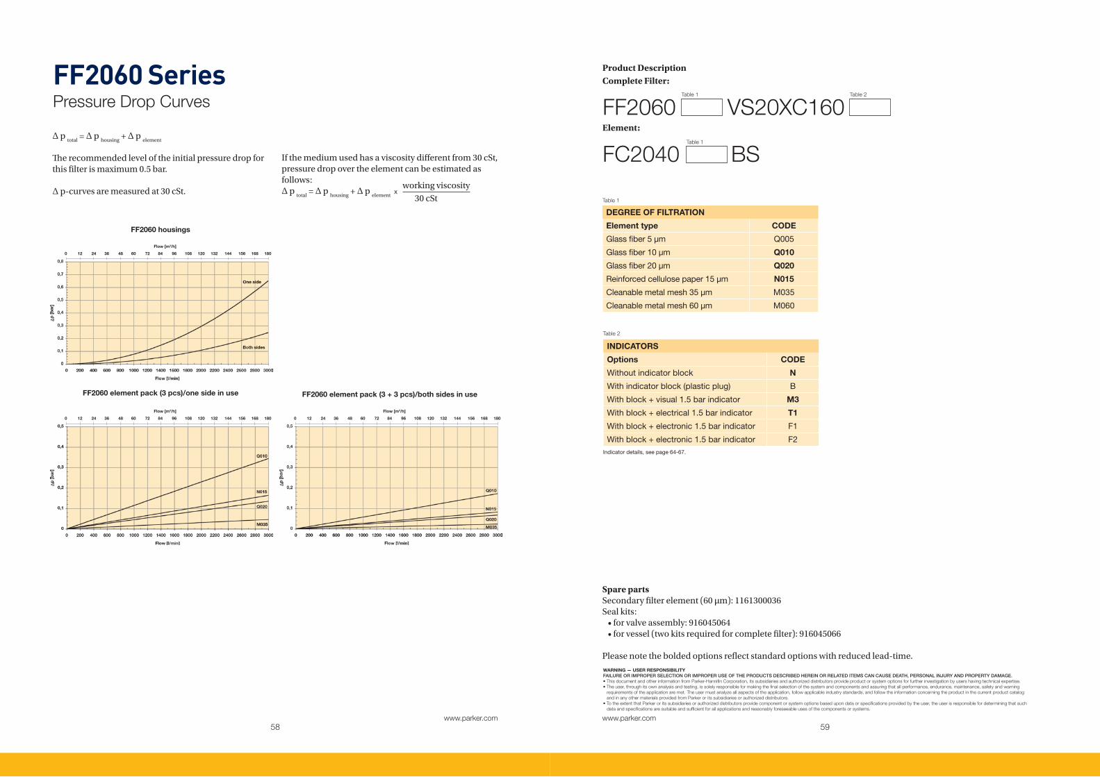
DEGREE OF FILTRATION
Element type CODE
Glassfiber5µm Q005
Glassfiber10µm Q010
Glassfiber20µm Q020
Reinforcedcellulosepaper15µm N015
Cleanablemetalmesh35µm M035
Cleanablemetalmesh60µm M060
Table 1
FF2060 SeriesPressure Drop Curves
Spare partsSecondary filter element (60 µm): 1161300036Seal kits: •forvalveassembly:916045064 •forvessel(twokitsrequiredforcompletefilter):916045066
Please note the bolded options reflect standard options with reduced lead-time.
INDICATORS
Options CODE
Withoutindicatorblock N
Withindicatorblock(plasticplug) B
Withblock+visual1.5barindicator M3
Withblock+electrical1.5barindicator T1
Withblock+electronic1.5barindicator F1
Withblock+electronic1.5barindicator F2
Table 2
Indicatordetails,seepage64-67.
FF2060 housings
FF2060 element pack (3 pcs)/one side in use FF2060 element pack (3 + 3 pcs)/both sides in use
∆ p total
= ∆ p housing
+ ∆ p element
The recommended level of the initial pressure drop for this filter is maximum 0.5 bar.
∆ p-curves are measured at 30 cSt.
If the medium used has a viscosity different from 30 cSt, pressure drop over the element can be estimated as follows: ∆ p
total = ∆ p
housing + ∆ p
element x
working viscosity
30 cSt
Flow [m3/h]
0 12 24 36 48 60 72 84 96 108 120 132 144 156 168 180
Flow [m3/h]
0 12 24 36 48 60 72 84 96 108 120 132 144 156 168 180
Flow [m3/h]
0 12 24 36 48 60 72 84 96 108 120 132 144 156 168 180
Table 1 Table 2
Product DescriptionComplete Filter:
Element:
FF2060 VS20XC160
FC2040 BS Table 1

61www.parker.com
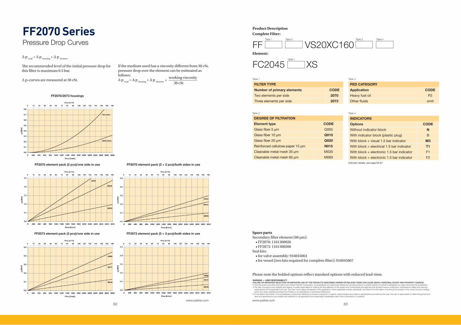
FF2070 SeriesDuplex Filters
Big and tall for high flowWelded housing construction with cast iron change over valve section. Compact, low-depth duplex construction for vertical mounting. High flow and good dirt holding capacity combined to low pressure drop. Several media options for heavy fuel oil and lube systems.
Applications:
• Dieselenginelubricatingsystems
• Highflowindustriallubricatingsystems
• Highflowheavyfueloilsystemsassafetyfilter
Contact Information:ParkerHannifinCorporationHydraulic Filter Division [email protected]
www.parker.com
Specification
Duplex filter:One reservoir can be closed for service.Connections:Square flanges with port size Ø160 mm. Standard delivery includes blind counter flanges.Maximum operating pressure: 10 bar Seal material: Fluoroelastomer*Operating temperature: -20°C...+120°C, for other temperatures consult Parker Filtration.Housing material: Steel/cast iron (GJS)Weight: FF2070: 310 kgFF2073: 400 kgNominal flow rate (30 cSt): FF2070: 1500 l/min (90 m3/h)FF2073: 1800 l/min (132 m3/h)Bypass valve:For the primary filter only, opening pressure 2.0 bar
Indicator options:Visual, electrical or electronic indicator requires an indicator block. For details see indicator options table in product description page. Primary filter:- Two filter elements per reservoir- Filtration materials •Resinimpregnatedheavydutycellulosepaper 15 µm nominal •GlassfiberMicroglassIII •CleanablemetalmeshSecondary filter:- One filter element per reservoir- Filtration material cleanable wire mesh- Filtration degree 60 µmFluid compatibility:Suitable for use with regular hydraulic and lubrication oils and fuel oils. For heavy fuel oil applications, please specify option P2 (see table 4 in product description) which ensures that filters are delivered with documen-tation according PED 97/23/EC category II. For other fluids consult Parker Filtration.
* Fluoroelastomers are available under various registered trademarks, including Viton (a registered trademark of DuPont) and Fluorel (a registered trademark of 3M).
Type A B C D E
FF2070 440 960 845 478 500
FF2073 706 1227 1112 745 560
62www.parker.com
63www.parker.com
WARNING — USER RESPONSIBILITYFAILURE OR IMPROPER SELECTION OR IMPROPER USE OF THE PRODUCTS DESCRIBED HEREIN OR RELATED ITEMS CAN CAUSE DEATH, PERSONAL INJURY AND PROPERTY DAMAGE.• This document and other information from Parker-Hannifin Corporation, its subsidiaries and authorized distributors provide product or system options for further investigation by users having technical expertise. • The user, through its own analysis and testing, is solely responsible for making the final selection of the system and components and assuring that all performance, endurance, maintenance, safety and warning requirements of the application are met. The user must analyze all aspects of the application, follow applicable industry standards, and follow the information concerning the product in the current product catalog and in any other materials provided from Parker or its subsidiaries or authorized distributors. • To the extent that Parker or its subsidiaries or authorized distributors provide component or system options based upon data or specifications provided by the user, the user is responsible for determining that such data and specifications are suitable and sufficient for all applications and reasonably foreseeable uses of the components or systems.
Table 1 Table 2 Table 3 Table 4
DEGREE OF FILTRATION
Element type CODE
Glassfiber5µm Q005
Glassfiber10µm Q010
Glassfiber20µm Q020
Reinforcedcellulosepaper15µm N015
Cleanablemetalmesh35µm M035
Cleanablemetalmesh60µm M060
Table 2
FF2070 SeriesPressure Drop Curves
Spare partsSecondary filter element (60 µm): •FF2070:1161300026 •FF2073:1161300206Seal kits: •forvalveassembly:916045064 •forvessel(twokitsrequiredforcompletefilter):916045067
Please note the bolded options reflect standard options with reduced lead-time.
INDICATORS
Options CODE
Withoutindicatorblock N
Withindicatorblock(plasticplug) B
Withblock+visual1.5barindicator M3
Withblock+electrical1.5barindicator T1
Withblock+electronic1.5barindicator F1
Withblock+electronic1.5barindicator F2
Table 4
Indicatordetails,seepage64-67.FF2070 element pack (2 pcs)/one side in use FF2070 element pack (2 + 2 pcs)/both sides in use
FF2073 element pack (3 pcs)/one side in use FF2073 element pack (3 + 3 pcs)/both sides in use
FILTER TYPE
Number of primary elements CODE
Twoelementsperside 2070
Threeelementsperside 2073
Table 1
∆ p total
= ∆ p housing
+ ∆ p element
The recommended level of the initial pressure drop for this filter is maximum 0.5 bar.
∆ p-curves are measured at 30 cSt.
If the medium used has a viscosity different from 30 cSt, pressure drop over the element can be estimated as follows: ∆ p
total = ∆ p
housing + ∆ p
element x
working viscosity
30 cSt
FF2070/2073 housings
0 12 24 36 48 60 72 84 96 108 120 132 144 156 168 180
Flow [m3/h]
0 12 24 36 48 60 72 84 96 108 120 132 144 156 168 180
Flow [m3/h]
0 12 24 36 48 60 72 84 96 108 120 132 144 156 168 180
Flow [m3/h]
0 12 24 36 48 60 72 84 96 108 120 132 144 156 168 180
Flow [m3/h]
0 12 24 36 48 60 72 84 96 108 120 132 144 156 168 180
Flow [m3/h]
Product DescriptionComplete Filter:
Element:
FF VS20XC160
FC2045 XS Table 1
PED CATEGORY
Application CODE
Heavyfueloil P2
Otherfluids omit
Table 3

65www.parker.com
Ø 24
Redcolourvisiblewhenindicatoron
M1-typepushhereforreset
Highpressure
Highpressure¾-16UNF-2A
Ø 16.2 ± 0.05
27.5
55.5
FMU IndicatorsDifferential Pressure Indicators
Contact Information:ParkerHannifinCorporationHydraulic Filter Division [email protected]
www.parker.com
Specification
Maximum operating pressure:420 barMaximum differential pressure:210 barWorking temperature range:-20°C to +85°C, note FMUF thermal lock at +20°C Material of housing:Brass or stainless steelSeals:Fluoroelastomer as standard (code V). For other seal material options, please contact Parker Filtration.The differential pressure values of standard indicator models: 1.0 bar ± 0.11.5 bar ± 0.22.5 bar ± 0.2
(Indicators for other differential pressure values are op-tional).
Accurate feedback The FMU range of filter condition indicators are designed for use on almost any Parker heavy duty filter and suitable for competitive interchange too. These pressure indicators give electronic, electrical or visual feedback of filter element condition. Accurate feedback ensures effective maintenance and scheduled element change.
Applications:
• Industrialequipment• Mobileequipment• Marineandoffshoreapplications
• Competitorhousing
FMUM3 Visual Auto Reset/FMUM1 Visual Manual Reset
Operation
FMUT1 Electrical
Contact configuration
Rated voltage
Non-inductive load (A) Inductive load (A)Inrush current (A)Resistiveload Lampload Inductiveload Motorload
N.C. N.O. N.C. N.O. N.C. N.O. N.C. N.O. N.C. N.O.
125VAC 5 1.5 0.7 3 2.5 1.3
20max.
10max.
250VAC 3 1.0 0.5 2 1.5 0.8
8VDC 5 2 5 4 3
14VDC 5 2 4 4 3
30VDC 4 2 3 3 3
125VDC 0.4 0.05 0.4 0.4 0.05
250VDC 0.2 0.03 0.2 0.2 0.03
Enclosureclass IP65
Electricalconnector DIN43650
Overvoltagecategory II(EN61010-1)
P1-P2
Noconnect
Pin 2 3 1
COM
Indication(N.O
)
Normallyclose
d(N
.C)
Rotatingpart360°
P1highpressure
P2lowpressure
Fixedpart
¾-16UNF-2AØ 16.2 ± 0.05
27.5
98

66www.parker.com
67www.parker.com
WARNING — USER RESPONSIBILITYFAILURE OR IMPROPER SELECTION OR IMPROPER USE OF THE PRODUCTS DESCRIBED HEREIN OR RELATED ITEMS CAN CAUSE DEATH, PERSONAL INJURY AND PROPERTY DAMAGE.• This document and other information from Parker-Hannifin Corporation, its subsidiaries and authorized distributors provide product or system options for further investigation by users having technical expertise. • The user, through its own analysis and testing, is solely responsible for making the final selection of the system and components and assuring that all performance, endurance, maintenance, safety and warning requirements of the application are met. The user must analyze all aspects of the application, follow applicable industry standards, and follow the information concerning the product in the current product catalog and in any other materials provided from Parker or its subsidiaries or authorized distributors. • To the extent that Parker or its subsidiaries or authorized distributors provide component or system options based upon data or specifications provided by the user, the user is responsible for determining that such data and specifications are suitable and sufficient for all applications and reasonably foreseeable uses of the components or systems.
Table 1 Table 2 Table 3 Table 4
Indicator SeriesFMU ∆p-Indicators
Seal kit ordering code: Fluoroelastomer: 911045078
Product Description
FMU V U12HX1 Atex approved electronic
FMUF Electronic
Enclosureclass IP65
Electricalconnector DIN43650,cableconnectionPG9
Inputsupplyvoltage +10to36VDC
*Indicationoutput maximum300mA/36VDC
Outputtype N.O.,NPNorPNP
Ind. press. setting
LED status Output
G Y1 Y2 R
< 50 % -
50 % -
75 % active
100 % active
2
1
Specification:• Equipmentcategory2(forzone1): Ex II 2 GD Eex m II T6• Maxtemperature85°C• SupplyVoltage:10–36Vdc• Current300mA(max)• I
kmax: 1A
Contact configuration
NPN
PNP
FPC.FNPN
Normallyopen(N.O)
FPC.FPNP
Normallyopen(N.O)
3
3
+V
+V
+10...36VDC
+10...36VDC
0V
0V
1
1
2
2
4
4
Load
Load
Load
Load
*
*
*
*
*max300mA
*max300mA
Rotatingpart360°
GreenLED
YellowLED’s
RedLED
Highpressure
Lowpressure
Fixedpart
¾-16UNF-2AØ 16.2 ± 0.05
27.5
98
Thermal lock-out setting +20°C•Indicatoroperatesonlywhentemperatureisabove setting.
Note:Donotconnectoutputterminals1or2directly(withoutload)topowersupply
terminals,becausethiswilldamagetheequipment.
INDICATOR TYPE
Indicator options CODEVisualΔpindicator(autoreset) M3
VisualΔpindicator(manualreset) M1
ElectricalΔpindicator T1
Electronic,4LED,PNP,N.O. F1
Electronic,4LED,NPN,N.O. F2
Atexapprovedelectronic X1
Table 1
BODY MATERIAL
Standard body material CODEBrass M
OptionalbodymaterialStainlesssteel R
Table 3
OPTIONS
Setting for F1, F2, X1 types CODEThermallock-outstandard+20° omit
Otheroptionsbyrequest factorysupplied
Table 4
INDICATING PRESSURE
Indicating pressure options CODE1.0bar F
1.5bar H
2.5bar K
Table 2
Otherindicatingpressuresavailable.
Cable5meterØ 32
57
HEX24(Ø26.5mm)
7/8-14UNF-2AU14M(W3)andU14H(W6)shapesor3/4-16UNF-2AU12H(F6)shape

68www.parker.com
69www.parker.com
1
4
5 67
9
Parker RacorMarine Filtration Solutions
The name to trust in marine filtrationParker Filtration has worked closely with marine system designers and developers over many years, supplying filtration solutions for many applications in the marine sector.
Parker Racor’s global solutions in fuel filtration and separation, together with the innovations of our partners have resulted in product excellence. Co- operation with major engine and propulsion system manufacturers, steering and winch manufacturers, refrigeration system designers through to passenger lift manufacturers and hydraulic system engineers has generated solutions that are unbeatable in the harshest conditions.
Related industries, such as offshore, with applications that include well-head lubrication, hydraulic systems and winch control provide ample opportunity for Parker Filtration to demonstrate quality in filtration manufacturing. Qualities that add up to reliable per-formance, long-term durability and efficient operation from bow to stern making Parker Filtration a reliable choice for marine filtration applications.
Parker Racor’s design excellence and product inno-vation has created some value added advantages in the marine market.
1 2Fuel DeliveryThe RV Series vessels are designed to be used in bulk fuel storage, fuel dispensing, or in fuel transfer and large engine applications. RV Series set up as a filter/ water separator (RVFS) will remove mulsified free water and solids from diesel fuel, gasoline, and other hydrocarbon streams. When equipped with filter water separator elements, water can be drained and removed from the RVFS sump. RV Series set up as a particulate filter (RVMF) is designed to remove solid contaminants such as dirt, rust, scale, and other solid materials from a hydrocarbon fuel stream down to two micron.
Top-Load Oil FiltersRacor’s top-load oil filters are permanent assemblies with cartridge elements. An uncompromising, high level of fluid cleanliness is needed to achieve operating efficiency and reach service life. The envi-ronmentally-friendly cartridge oil filters are crushable, incinerable and cost-effective to replace. Filter service is from the top of the module and skin contact is minimal due to the unique screw top cap and oil element attachment. The permanent assembly is customized with a patented automatic drain that allows oil to drain back into the sump when the engine is turned off and the screw top cap is removed for service.
3
5
74
6
8
9
Marine Hose & FittingsParker Marine Hose is a USCG-rated hose for gasoline, diesel, lube oil and hydraulic systems for commercial and recreational applications. It is fire-resistant and meets SAE J1527 Type A class 1 and SAE J1942 standards. As you’d expect, it delivers test-proven performance in a wide operating temperature range and constant working pressure. It is of a long-lasting reinforced construction, kink and cut resistant, and compatible with a variety of standard 100R5 fittings.
Diesel Fuel Filter/Water Separators & PumpsWhen engines demand heavy-duty, high-capacity water separation and fuel filtration, the Turbine Series is the most complete, efficient and reliable engine protection you can install. Symbolizing Racor’s continuing commitment to the science of filtration, the Turbine Series has established its position as the filter/sepa-rator often imitated, but never equaled.Models that include an aluminum bowl or stainless steel shield meet ASTM FS1201 certification, are ULlisted, American Bureau of Shipping, Veritas, Det Norske Veritas, ISO 10088 and U.S.C.G. accepted. For severe service, all-metal bowls should be specified.
Air Filter/SilencerThe Racor marine air filter/silencer removes contaminants introduced into the air from both outside and inside the vessel. Sand, salt, carpet fibers and other contami-nants are trapped in the oil-impregnated filter media. Turbo noise is reduced by the unique design of the air filter/silencer housing. An integral hose connection on the housing routes the clean blow-by from the CCV back into the engine.
Crankcase FiltrationIn a robust, compact package, the patented Racor CCV closed crankcase ventilation filter systems provide superior oil coa-lescence and crankcase pressure control under the most severe conditions. The only routine maintenance required for the Racor Crankcase Ventilation Filter System is filter replacement. Typical service life of the high-performance filter in diesel applications is 750 hours. Some variations in service life occur depending on load profile, engine wear condition, flow and aerosol mass concentration of crankcase emissions, and soot concentration.
Bypass Oil FiltersThe Racor Bypass Oil Series removes dirt, varnish, ash, tar, soot and other contami-nants that full-flow filters cannot remove from your engine’s oil and hydraulic systems. The system also removes condensed water, which forms component-damaging acids if left in the oil. The Racor Bypass Oil Series removes damaging contaminants to mini-mize wear and extends engine component life. The Racor bypass element has a 1 micron nominal rating.
In-Line Gasoline FiltersRacor’s In-line Gasoline Filter Series keeps your fuel clean and dry, because having grime and water in your fuel spells disaster. More than ever, today’s high performance gasoline engines require clean, dry fuel. Standard fuel filters simply succumb from normal usage, and don’t offer the improved features, durability and peace-of-mind that comes with Racor fuel filters. Experienced sailors rust their engines, their livelihood, and even their lives to Racor’s high quality marine products. Shouldn’t you?
Hydraulic FiltersRacor water-absorbing hydraulic filters feature a specially designed media that traps not only solid contaminants like dirt and rust, but damaging water as well. Water absorbing spin-on hydraulic filters are available for virtually any application and are available in a 10 micron nominal rating. Racor resin-impregnated hydraulic filters include media that traps solid contami-nants like dirt and rust as it repels water. Resin-impregnated hydraulic filters are available for virtually any application and are available in a 10 micron nominal rating.

71www.parker.com
Marine PAR FIT TM
Interchangeable Element Range
Contact Information:ParkerHannifinCorporationHydraulic Filter Division [email protected]
www.parker.com
The replacement solutionWith over 20 000 standard, off the shelf variations, there’s a PAR FIT™ element to fit most sizes and makes of filters on mobile, construction, agricultural and industrial plant. Every PAR FIT™ element is manufactured in Europe to the highest standards and is backed by our unrivalled technical support and money back guarantees.
You can reduce stockholdings, cut costs and be sure of the ultimate performance. PAR FIT™ filters are available from ParkerStores and authorised distributors throughout Europe.
www.parker.com/parfit
Typical Applications:
• Industrialpowerunits• Centrallubricationsystems• Dieselenginelubrication• Marinefuelsystems• Powerplants• Gearboxes• Windturbines
FEATURES ADVANTAGES BENEFITSMicroglassIIIreplacementelements Multi-layereddesignproducing
highdirtholdingcapasityandhighefficiency
Greatperformancevalue
Wiresupportreducespleatbunchingandkeepsperformanceconsistent
Reliableperformancethroughoutelementlife
Reducesdowntimeandmaximiseselenmtlife
CorelessEcoglassIIIreplacementelements
Nometalcontentinelement Enviromentallyfriendlydisposalbyincineration
Reducedoverallweightof50% Lowerelementreplacementcosts
Easycompactionofusedelements Lowerdisposalcosts
Ecoadaptersavailable Retrofitcorlessdesigntohousingsalreadyinstalled
Completeperformancedatadisclosure
Allpertinentinformationisprovidedinaneasytocompareformat
Nohiddendeficiencies
Easyselectionofcorrectinterchangepartnumber
Elementsmanufacturedtoexactingstandardsoforiginalelements
Performanceguaranteeasgoodifnotbetterthanoriginalfit
Durable,ruggedandreliableconstructionwithhighqualitystandards
COMPETITOR COMPETITOR PART NUMBER PARKER PART NUMBERBollandKirch 1143103 939319Q
BollandKirch 1174632(11843GEW.300/250h=230,37um) 939317Q
BollandKirch 1174804 (11843 GEW.300/40) 939312Q
BollandKirch 1179995 (11844 GEW.300/40) 939311Q
BollandKirch 1340006(660-63filtercandlepleated10um) 939307Q
BollandKirch 1340009(250-40filtercandle25um) 939305Q
BollandKirch 1340079(294-31filtercandle34um) 939306Q
BollandKirch 1940971 (11443 GEW.324/34) 939310Q
BollandKirch 1940990 (11513 GEW.275/34) 939309Q
BollandKirch 1942562 (11445 GEW.155/100) 939318Q
BollandKirch 1943048 (11531 GEW.205/34) 939308Q
BollandKirch 1945279 (11531 GEW.205/40) 939314Q
BollandKirch 1946344 (11445 GEW.155/40) 939313Q
BollandKirch 1947342(Ø=85,h=244,40um) 939316Q
BollandKirch 1949798(Ø=85,h=195,40um) 939315Q
BollandKirch 7605706(Flushingoilelement6.61.07GR10-15,h=508+36) 939329Q
BollandKirch 7608089(Flushingoilelement6.61.07GR20,h=760+36) 939330Q
Morepartnumbersonthenextpage.

72www.parker.com
WARNING — USER RESPONSIBILITYFAILURE OR IMPROPER SELECTION OR IMPROPER USE OF THE PRODUCTS DESCRIBED HEREIN OR RELATED ITEMS CAN CAUSE DEATH, PERSONAL INJURY AND PROPERTY DAMAGE.• This document and other information from Parker-Hannifin Corporation, its subsidiaries and authorized distributors provide product or system options for further investigation by users having technical expertise. • The user, through its own analysis and testing, is solely responsible for making the final selection of the system and components and assuring that all performance, endurance, maintenance, safety and warning requirements of the application are met. The user must analyze all aspects of the application, follow applicable industry standards, and follow the information concerning the product in the current product catalog and in any other materials provided from Parker or its subsidiaries or authorized distributors. • To the extent that Parker or its subsidiaries or authorized distributors provide component or system options based upon data or specifications provided by the user, the user is responsible for determining that such data and specifications are suitable and sufficient for all applications and reasonably foreseeable uses of the components or systems.
Marine PAR FIT TM
COMPETITOR COMPETITOR PART NUMBER PARKER PART NUMBERMannandHummel BF-1018/1 939332Q
MannandHummel H-1081 939321Q
MannandHummel H-12178 939323Q
MannandHummel H-12225 939324Q
MannandHummel H-15111/2 939338Q
MannandHummel H-15190 939331Q
MannandHummel H-15222/2 939333Q
MannandHummel H-18300 939327Q
MannandHummel H-20211 939335Q
MannandHummel H-25444 939334Q
MannandHummel H-25595 939326Q
MannandHummel H-25669 939325Q
MannandHummel H-28545 939336Q
MannandHummel H-601/4 939320Q
MannandHummel H-930 939328Q
MannandHummel P-19185 939337Q
Pall HC8300FKN16H PR2798Q
Pall HC8300FKN26H 939340Q
Pall HC8300FKN39H 932873Q
Pall HC8300FKP16H PR3455Q
Pall HC8300FKP26H 939339Q
Pall HC8300FKP39H 932872Q
Pall HC8300FKS16H PR3456Q
Pall HC8300FKS26H 937156Q
Pall HC8300FKS39H 932874Q
Pall HC8300FKT16H 933047Q
Pall HC8300FKT26H 937158Q
Pall HC8300FKT39H 932875Q
Pall HC8304FKN16H 937165Q
Pall HC8304FKN39H 937166Q
Pall HC8304FKP16H 937167Q
Pall HC8304FKP39H 937168Q
Pall HC8304FKS16H 937169Q
Pall HC8304FKS39H 937170Q
Pall HC8304FKT16H 937171Q
Pall HC8304FKT39H 937172Q
Vokes B-62982 939303Q
Vokes B-6358174 939301Q
Vokes C-6352910 939322Q
Vokes C-6360352 939304Q
Vokes C-F7 939302Q
Together, we can reduce operator stress and keep freight rolling on and rolling off. With Parker Filtration’s heavy duty fuel and lube filter solutions it should be a calm crossing.
Be it different oils or gas used as fuel, the machinery keeps running and the transmission stays in shape. Automatic and clean, also for the environment – today and tomorrow.For more information on our stress-reducing marine filtration solutions, please visit: www.ro-ro-ro.com. Together we can keep marine machinery operating and freight rolling.

74www.parker.com
Important Information
WARNING!
Parker Hannifin Filter Division Europe, herewith declares that Parker Hydraulic Filtration products are intended to be incorporated into machinery covered by Directive 97/23/EC, as amended and that the following harmonised standards have been applied;EN982EN292-1EN292-2 We furthermore declare that, machinery incorporating Parker Hydraulic Filtration products is not allowed to be put into service until the machinery has been found and declared to be in conformity with, the provisions of Directive 97/23/EC and with national implementing legislation.
FAILURE OR IMPROPER SELECTION OR IMPROPER USE OF THE PRODUCTS AND/OR SYSTEMS DESCRIBED HEREIN OR RELATED ITEMS CAN CAUSE DEATH, PERSONAL INJURY AND PROPERTY DAMAGE. This document and other information from Parker Hannifin Corporation, its subsidiaries and authorised distributors provide product and/or system options for further investigation by users having technical exper-tise. It is important that you analyse all aspects of your application and review the information concerning the product or system in the current product catalogue.
AEROSPACEKey Markets� Aircraft engines� Business & general aviation� Commercial transports� Land-based weapons systems� Military aircraft� Missiles & launch vehicles� Regional transports� Unmanned aerial vehicles
Key Products� Flight control systems
& components� Fluid conveyance systems� Fluid metering delivery
& atomization devices� Fuel systems & components� Hydraulic systems & components� Inert nitrogen generating systems� Pneumatic systems & components� Wheels & brakes
CLIMATE CONTROLKey Markets� Agriculture� Air conditioning� Food, beverage & dairy� ���� �������� � �������� Precision cooling� Processing� Transportation
Key Products� CO2 controls� Electronic controllers� Filter driers� Hand shut-off valves� Hose & fittings� Pressure regulating valves� Refrigerant distributors� Safety relief valves� Solenoid valves� Thermostatic expansion valves
FILTRATIONKey Markets� Food & beverage� Industrial machinery� Life sciences� Marine� Mobile equipment� Oil & gas� Power generation� Process� Transportation
Key Products� Analytical gas generators� Compressed air & gas filters� Condition monitoring� Engine air, fuel & oil filtration
& systems� Hydraulic, lubrication &
coolant filters� Process, chemical, water
& microfiltration filters� Nitrogen, hydrogen & zero
air generators
ELECTROMECHANICALKey Markets� Aerospace� Factory automation� Life science & medical� Machine tools� Packaging machinery� Paper machinery� Plastics machinery & converting� Primary metals� Semiconductor & electronics� Textile� Wire & cable
Key Products� AC/DC drives & systems� Electric actuators, gantry robots
& slides� Electrohydrostatic actuation systems� Electromechanical actuation systems� Human machine interface� Linear motors� Stepper motors, servo motors,
drives & controls� Structural extrusions
PNEUMATICSKey Markets� Aerospace� Conveyor & material handling� Factory automation� Life science & medical� Machine tools� Packaging machinery� Transportation & automotive
Key Products� Air preparation� Brass fittings & valves� Manifolds� Pneumatic accessories� Pneumatic actuators & grippers� Pneumatic valves & controls� Quick disconnects� Rotary actuators� Rubber & thermoplastic hose
& couplings� Structural extrusions� Thermoplastic tubing & fittings� Vacuum generators, cups & sensors
FLUID & GAS HANDLINGKey Markets� Aerospace� Agriculture� Bulk chemical handling� Construction machinery� Food & beverage� Fuel & gas delivery� Industrial machinery� Mobile� Oil & gas� Transportation� Welding
Key Products� Brass fittings & valves� Diagnostic equipment� Fluid conveyance systems� Industrial hose� PTFE & PFA hose, tubing &
plastic fittings� Rubber & thermoplastic hose
& couplings� Tube fittings & adapters� Quick disconnects
HYDRAULICSKey Markets� Aerospace� Aerial lift� Agriculture� Construction machinery� Forestry� Industrial machinery� Mining� Oil & gas� Power generation & energy� Truck hydraulics
Key Products� Diagnostic equipment� Hydraulic cylinders
& accumulators� Hydraulic motors & pumps� Hydraulic systems� Hydraulic valves & controls� Power take-offs� Rubber & thermoplastic hose
& couplings� Tube fittings & adapters� Quick disconnects
PROCESS CONTROLKey Markets� Chemical & refining� Food, beverage & dairy� Medical & dental� Microelectronics� Oil & gas� Power generation
Key Products� Analytical sample conditioning
products & systems� Fluoropolymer chemical delivery
fittings, valves & pumps� High purity gas delivery fittings,
valves & regulators� Instrumentation fittings, valves
& regulators� Medium pressure fittings & valves� Process control manifolds
SEALING & SHIELDINGKey Markets� Aerospace� Chemical processing� Consumer� Energy, oil & gas� Fluid power� General industrial� Information technology� Life sciences� Military� Semiconductor� Telecommunications� Transportation
Key Products� Dynamic seals� Elastomeric o-rings� EMI shielding� Extruded & precision-cut,
fabricated elastomeric seals� Homogeneous & inserted elastomeric
shapes� High temperature metal seals� Metal & plastic retained composite
seals� Thermal management
Parker’sMotion&Control TechnologiesAt Parker, we’re guided by
a relentless drive to help
our customers become more
productive and achieve
higher levels of profitability
by engineering the best sys-
tems for their requirements.
It means looking at customer
applications from many
angles to find new ways to
create value. Whatever the
motion or control technology
need, Parker has the experi-
ence, breadth of product and
global reach to consistently
deliver. No company knows
more about motion and con-
trol technology than Parker.
In line with our policy of continuous product improve-ment, Parker Hannifin reserve the right to alter product data and specification without notice. This does not affect your statutory rights. Within this catalogue, each product has been allocated an operating temperature range and fluid compatibil-ity. The range listed for each filter is dictated by the materials of construction and the capability of the seals specified. Consideration should also be given to the characteristics of the system fluid when specifying filters for extreme temperature applications. The use of non Parker replacement elements and spares may invalidate your warranty.
Due to the variety of operating conditions and applica-tions for these products or systems, the user, through its own analysis and testing, is solely responsible for making the final selection for the products and system and assuring that all performance, safety and warning requirements of the application are met. The products described herein, including without limitation, product features, specifications, designs, availability and pricing, are subject to change by Parker Hannifin Corporation and its subsidiaries at any time without notice.

Ed.0
9/20
08
www.parker.com
AE – UAE, Dubai Tel:+97148127100 [email protected]
AR – Argentina, BuenosAires Tel:+543327444129
AT – Austria, WienerNeustadt Tel:+43(0)262223501-0 [email protected]
AT – Eastern Europe, WienerNeustadt Tel:+43(0)262223501970 [email protected]
AU – Australia, CastleHill Tel:+61(0)2-96347777
AZ – Azerbaijan, Baku Tel:+994502233458 [email protected]
BE/LU – Belgium, Nivelles Tel:+32(0)67280900 [email protected]
BR – Brazil, CachoeirinhaRS Tel:+555134709144
BY – Belarus, Minsk Tel:+375172099399 [email protected]
CA – Canada, Milton,Ontario Tel:+19056933000
CH – Switzerland, Etoy Tel:+41(0)218210230 [email protected]
CN – China, Shanghai Tel:+862150312525
CZ – Czech Republic, Klecany Tel:+420284083111 [email protected]
DE – Germany, Kaarst Tel:+49(0)213140160 [email protected]
DK – Denmark, Ballerup Tel:+4543560400 [email protected]
ES – Spain, Madrid Tel:+34902330001 [email protected]
FI – Finland, Vantaa Tel:+358(0)207532500 [email protected]
FR – France, Contamines/Arve Tel:+33(0)450258025 [email protected]
GR – Greece, Athens Tel:+302109336450 [email protected]
HK – Hong Kong Tel:+85224288008
HU – Hungary, Budapest Tel:+3612204155 [email protected]
IE – Ireland, Dublin Tel:+353(0)14666370 [email protected]
IN – India, Mumbai Tel:+912265137081-85
IT – Italy, Corsico(MI) Tel:+3902451921 [email protected]
JP – Japan, Tokyo Tel:+(81)364083901
KR – South Korea, Seoul Tel:+8225590400
KZ – Kazakhstan,Almaty Tel:+77272505800 [email protected]
LV – Latvia, Riga Tel:+37167452601 [email protected]
MX – Mexico, Apodaca Tel:+528181566000
MY – Malaysia, SubangJaya Tel:+60356381476
NL – The Netherlands, Oldenzaal Tel:+31(0)541585000 [email protected]
NO – Norway, Ski Tel:+4764911000 [email protected]
NZ – New Zealand, MtWellington Tel:+6495741744
PL – Poland, Warsaw Tel:+48(0)225732400 [email protected]
PT – Portugal, LecadaPalmeira Tel:+351229997360 [email protected]
RO – Romania, Bucharest Tel:+40212521382 [email protected]
RU – Russia, Moscow Tel:+7495645-2156 [email protected]
SE – Sweden, Spånga Tel:+46(0)859795000 [email protected]
SG – Singapore Tel:+6568876300
SK – Slovakia, BanskáBystrica Tel:+421484162252 [email protected]
SL – Slovenia, NovoMesto Tel:+38673376650 [email protected]
TH – Thailand, Bangkok Tel:+6627178140
TR – Turkey, Istanbul Tel:+902164997081 [email protected]
TW – Taiwan, Taipei Tel:+886222988987
UA – Ukraine, Kiev Tel+380444942731 [email protected]
UK – United Kingdom, Warwick Tel:+44(0)1926317878 [email protected]
US – USA, Cleveland Tel:+12168963000
VE – Venezuela, Caracas Tel:+582122385422
ZA – South Africa, KemptonPark Tel:+27(0)119610700 [email protected]
CatalogueFDHB398UK
YourlocalauthorizedParkerdistributor
©2008ParkerHannifinCorporation.Allrightsreserved.
ParkerWorldwide
ForfurtherinformationonParkerproducts:ContactyourlocalParkerSalesCompany(Detailsabove)CallEPICfreeon0080027275374(fromAT,BE,CH,CZ,DE,EE,ES,FI,FR,IE,IT,PT,SE,SK,UK)


![Arkal Filters Catalogue - Irrigation Works1].pdf7 Maximum Filtration Flow Rate / Water Quality Technical Data METRIC US Max. pressure bar 10 psi 145 Min. filtration pressure bar 2.8](https://static.fdocuments.net/doc/165x107/61199dec542d657e1f36442e/arkal-filters-catalogue-irrigation-works-1pdf-7-maximum-filtration-flow-rate.jpg)


