HEATING VENTILATING, AND AIR-CONDITIONING …...DIVISION 23 – HEATING VENTILATING, AND...
49
UNIVERSITY OF NORTH DAKOTA – DESIGN STANDARDS page 1 REVISED OCTOBER 2015 DIVISION 23 – HVAC DIVISION 23 – HEATING VENTILATING, AND AIR-CONDITIONING (HVAC) 23 0130.51 – HVAC AIR DUCT CLEANING A. CLEANING 1. Comply with NADCA ACR 2006. 2. Systems and Components to Be Cleaned: a. Air terminal units b. Air devices for supply and return air c. Air-handling units: 1) Interior surfaces of the unit casing. 2) Coil surfaces compartment. 3) Condensate drain pans. 4) Fans, fan blades, and fan housings. d. Ductwork e. Filters and filter housings. 3. Particulate Collection: a. HEPA filtration with 99.97 percent collection efficiency for particles sized 0.3 micrometer or larger shall be used where the particulate collection equipment is exhausting inside the building. b. Control odors and mist vapors during the cleaning and restoration process 4. Duct Systems: a. Mechanically clean duct systems specified to remove all visible contaminants so that the systems are capable of passing the HVAC System Cleanliness Tests (see NADCA ACR 2006). b. Create service openings as necessary to accommodate cleaning 5. Mechanical Cleaning Methodology: 1) Use continuously operating vacuum-collection devices to keep each section being cleaned under negative pressure. 6. Cleaning Mineral-Fiber Insulation Components: 1) Fibrous-glass thermal or acoustical insulation elements present in equipment or ductwork shall be thoroughly cleaned with HEPA vacuuming equipment while the HVAC system is under constant negative pressure and shall not be permitted to get wet according to NADCA ACR 2006. 7. Coil Cleaning: a. Measure static-pressure differential across each coil and document before and after.
Transcript of HEATING VENTILATING, AND AIR-CONDITIONING …...DIVISION 23 – HEATING VENTILATING, AND...

UNIVERSITY OF NORTH DAKOTA – DESIGN STANDARDS page 1 REVISED OCTOBER 2015 DIVISION 23 – HVAC
DIVISION 23 – HEATING VENTILATING, AND AIR-CONDITIONING (HVAC)
23 0130.51 – HVAC AIR DUCT CLEANING
A. CLEANING
1. Comply with NADCA ACR 2006.
2. Systems and Components to Be Cleaned: a. Air terminal units b. Air devices for supply and return air c. Air-handling units:
1) Interior surfaces of the unit casing. 2) Coil surfaces compartment. 3) Condensate drain pans. 4) Fans, fan blades, and fan housings.
d. Ductwork
e. Filters and filter housings.
3. Particulate Collection: a. HEPA filtration with 99.97 percent collection efficiency for particles sized 0.3 micrometer
or larger shall be used where the particulate collection equipment is exhausting inside the building.
b. Control odors and mist vapors during the cleaning and restoration process
4. Duct Systems: a. Mechanically clean duct systems specified to remove all visible contaminants so that the
systems are capable of passing the HVAC System Cleanliness Tests (see NADCA ACR 2006).
b. Create service openings as necessary to accommodate cleaning
5. Mechanical Cleaning Methodology:
1) Use continuously operating vacuum-collection devices to keep each section being cleaned under negative pressure.
6. Cleaning Mineral-Fiber Insulation Components:
1) Fibrous-glass thermal or acoustical insulation elements present in equipment or ductwork shall be thoroughly cleaned with HEPA vacuuming equipment while the HVAC system is under constant negative pressure and shall not be permitted to get wet according to NADCA ACR 2006.
7. Coil Cleaning:
a. Measure static-pressure differential across each coil and document before and after.

UNIVERSITY OF NORTH DAKOTA – DESIGN STANDARDS page 2 REVISED OCTOBER 2015 DIVISION 23 – HVAC
8. Antimicrobial Agents and Coatings: a. Sanitizing agent products shall be registered by the EPA as specifically intended for use in
HVAC systems and ductwork. 9. Requirement of Pleated Filters
a. Need to be clean and also provide a replacement set at completion of project.
23 0513 – COMMON MOTOR REQUIREMENTS FOR HVAC EQUIPMENT
A. GENERAL MOTOR REQUIREMENTS
1. Comply with NEMA MG 1 unless otherwise indicated.
2. Comply with IEEE 841 for severe-duty motors. 23 0516 – EXPANSION FITTINGS AND LOOPS FOR HVAC PIPING 23 0519 – METERS AND GAGES FOR HVAC PIPING
A. Each new construction project a condensate pump discharge that serves a building shall be fitted with a condensate meter. Install lockable, manual bypass valve around the meters.
1. Condensate Meter output shall be connection to the building automation system. Verify connection with Owner.
B. For the connection to the campus steam distribution system, there needs to be a meter measuring total facility steam consumption.
C. All metering systems must be compatible with existing campus metering. The following metering equipment or approved equivalents should be used:
1. BTU monitor model 3050-11 by Badger Meter (Technical brief available at http://www.badgermeter.com/Badger-Files/PDFs/Industrial-Products/DTB-077-Series-3050-Btu-Monitor-Tech-Brief.pdf)
a. Flow sensor SDI 2DIN21-0200 by Badger Meter (Technical brief available at http://www.badgermeter.com/Badger-Files/PDFs/Industrial-Products/DTB-002-SDI-Insert-Flow-Sensor-Tech-Brief.pdf)
2. Temperature sensor RTD1-C0603 and Thermowell TW06-01 from Automationdirect.com (Technical briefs available at http://www.automationdirect.com/static/specs/ Psrtdprobeslch.pdf and http://www.automationdirect.com/static/specs/psthermowellsl.pdf)
D. UND will purchase and install all meters. The project manager shall contact UND Facilities to install all utility meters, both temporary and permanent. The temp meter shall
UNIVERSITY OF NORTH DAKOTA – DESIGN STANDARDS page 3 REVISED OCTOBER 2015 DIVISION 23 – HVAC
remain active for the entire project. There shall be no more than 24 hours between the removal of the temporary meter and installation of the permanent meter.
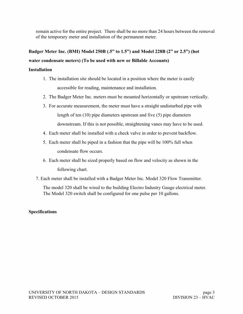
Badger Meter Inc. (BMI) Model 250B (.5” to 1.5”) and Model 228B (2” or 2.5”) (hot
water condensate meters) (To be used with new or Billable Accounts)
Installation
1. The installation site should be located in a position where the meter is easily
accessible for reading, maintenance and installation.
2. The Badger Meter Inc. meters must be mounted horizontally or upstream vertically.
3. For accurate measurement, the meter must have a straight undisturbed pipe with
length of ten (10) pipe diameters upstream and five (5) pipe diameters
downstream. If this is not possible, straightening vanes may have to be used.
4. Each meter shall be installed with a check valve in order to prevent backflow.
5. Each meter shall be piped in a fashion that the pipe will be 100% full when
condensate flow occurs.
6. Each meter shall be sized properly based on flow and velocity as shown in the
following chart.
7. Each meter shall be installed with a Badger Meter Inc. Model 320 Flow Transmitter.
The model 320 shall be wired to the building Electro Industry Gauge electrical meter. The Model 320 switch shall be configured for one pulse per 10 gallons.
Specifications

UNIVERSITY OF NORTH DAKOTA – DESIGN STANDARDS page 4 REVISED OCTOBER 2015 DIVISION 23 – HVAC
Model 250B and 228B
When connecting to the EIG unit, you need:
Qty. 1 ea.
Badger Meter Inc. Model 250B or 228B
Badger Model Inc. Model 320
A1026 Power Supply
The application you have already installed would include:
Qty. 1 ea.
Badger Meter Inc. Model 250B or 228B
Badger Meter Inc. Model 320
A1026 Power Supply
350T RF transmitter
WMM Water Meter Monitor
If you want to read the meter via wireless and plug it into the EIG:

UNIVERSITY OF NORTH DAKOTA – DESIGN STANDARDS page 5 REVISED OCTOBER 2015 DIVISION 23 – HVAC
Qty. 1 ea.
Badger Meter Inc. Model 250B or 228B
Badger Meter Inc. Model 320
A1026 Power Supply
350T RF transmitter
WMM Water Meter Monitor
350R RF receiver which will provide additional output for the EIG
NIAGARA Series MTX (hot water condensate meter) (Existing or Non-billable accounts)
Model 421
Installation
8. The installation site should be located in a position where the meter is easily
accessible for reading, maintenance and installation.
9. The Niagara MTX meter must be mounted horizontally with the register on top. 10. For accurate measurement, the meter must have a straight undisturbed pipe with
length of five (5) pipe diameters upstream and three (3) pipe diameters
downstream. If this is not possible, straightening vanes may have to be used.
11. Each meter shall be installed with a check valve in order to prevent backflow.
12. Each meter shall be piped in a fashion that the pipe will be 100% full when
condensate flow occurs.
13. Each meter shall be sized properly based on flow and velocity as shown in the
following chart.
14. Each meter shall be installed with a Niagra Model 840 switch. The model 840
switch shall be wired to the building Electro Industry Gauge (EIG) electrical
meter. The model 840 switch shall be configured for one pulse per 100 gallons.
Specifications

UNIVERSITY OF NORTH DAKOTA – DESIGN STANDARDS page 6 REVISED OCTOBER 2015 DIVISION 23 – HVAC
Model 421 (Hot)
1. UND Steam Service & Condensate Meter Procedure The purpose of this procedure is to maintain standards for metering of UND steam
services and steam condensate returned to the steam distribution system. The standards set forth in this procedure shall be enforced with new construction, existing buildings, and maintenance of steam and steam condensate metering systems.
New Construction:
Temporary Metering:
Prior to construction the project manager shall request a steam service to the construction site through UND Facilities Utility Accountant. A fund number or Org number will be required by UND Facilities Utility Accountant at this time. The UND plumbers shall provide and size the temporary meter. The temporary meter will be provided by UND at no cost project. The temporary meter shall be installed by UND Plumbers. The meter and steam installation shall be inspected and approved by the UND Plumbing Department before the steam is turned on. The temporary meter shall be read by UND Facilities Utility Accountant. The Utility Accountant shall be notified when the meter is to be removed from service by the project manager.
At no time will dumping of steam condensate or venting steam to atmosphere be allowed.
Billing penalties may be applied to the project and/or contractor if necessary.

UNIVERSITY OF NORTH DAKOTA – DESIGN STANDARDS page 7 REVISED OCTOBER 2015 DIVISION 23 – HVAC
Permanent Metering:
The permanent condensate metering shall be sized and installed based on UND steam condensate standards and the engineer on record for the construction project. The meter shall be provided by the construction project. All condensate meters shall be connected to
UND’s automated meter reading system under the construction contract. All equipment and wiring necessary to connect to UND’s automated meter reading system will be provided by the construction contract. All condensate leaving the facility shall be metered. Once the steam condensate meter is installed UND Facilities Utility Accountant shall be notified by the plumbers. The Utility Accountant shall then inventory and tag the meter. The permanent meter shall be read monthly by the UND Facilities Utility Accountant.
At no time will dumping of steam condensate or venting steam to atmosphere be allowed.
Billing penalties may be applied if necessary.
Existing Buildings:
The permanent condensate metering for each building shall be sized and installed based on UND steam condensate standards. The condensate meter shall be maintained in accordance with UND condensate meter maintenance procedures. The UND Plumbing Department shall be responsible for meter installation and maintenance. If provisions are available, the condensate meter shall be connected to UND’s automated meter reading system.
The Utility Accountant shall be responsible for inventory and tagging of the meter. The meter shall be read monthly by the UND Facilities Utility Accountant.
At no time will dumping of steam condensate or venting steam to atmosphere be allowed. In the event condensate must be dumped for emergency of maintenance purposes, the Communications Center shall be notified when dumping of the condensate began and when dumping of the condensate halted. The communications center shall also notify the UND Steam Plant and UND utility accountant.
Steam Customers:

UNIVERSITY OF NORTH DAKOTA – DESIGN STANDARDS page 8 REVISED OCTOBER 2015 DIVISION 23 – HVAC
The permanent condensate metering for each steam customer shall be sized and installed based on UND steam condensate standards. The condensate meter shall be maintained in accordance with UND condensate meter maintenance procedures. The UND Plumbing Department shall be responsible for meter installation and maintenance. If provisions are available, the condensate meter shall be connected to UND’s automated meter reading system.
The Utility Accountant shall be responsible for inventory and tagging of the meter. The meter shall be read monthly by the UND Facilities Utility Accountant.
Dumping of steam condensate or venting steam to atmosphere is not allowed. Billing penalties may be applied if necessary. In the event condensate must be dumped for emergency of maintenance purposes, the Communications Center shall be notified when dumping of the condensate began and when dumping of the condensate halted. The communications center shall also notify the UND Steam Plant and UND utility accountant.
An annual inspection of each billable meter shall be conduction by UND Facility
Plumbing department to determine condition of metering, piping, and maintenance needs. The UND Facilities PM system shall generate the work order for each annual inspection.
Meter Size and Installation Requirements:
The meter size and type shall be determined by UND Plumbing department or the engineer on record for a project. Each Condensate meter shall have a local register and must have an electrical contact output that will pulse each 10 or 100 gallons. The contact output shall be connected to the UND automated meter reading system.
See “Condensate Meter Policy Exhibit A” for approved meter types, sizes, and
installation instructions.
Meter Maintenance:
Condensate meter maintenance shall be performed by request of a work order. All condensate meter maintenance labor and material shall be charged to steam line distribution.

UNIVERSITY OF NORTH DAKOTA – DESIGN STANDARDS page 9 REVISED OCTOBER 2015 DIVISION 23 – HVAC
A work order may be requested by maintenance personnel, UND Utility Accountant, Steam Customer, building occupant, etc. A work order may be generated for but not limited to, the following reasons:
Non-working meter Meter suspected not to be accurate Leaking condensate Bad check valve Improper piping Testing and calibration
When a condensate meter is scheduled for maintenance, under no circumstances shall the meter be serviced in the field. When maintenance is conducted, the existing condensate meter will be removed from service. A new or refurbished; tested and certified condensate meter shall be installed and placed in service. The Facilities Department “Meter Change-out Form” shall be used in this process. The completed “Meter Change out Form” shall be forwarded to the UND Utility accountant.
The condensate meter removed from service shall be taken back to the Plumbers test station for repair, calibration, testing, and certification. Once the meter is tested and certified the meter can then be placed in inventory for use at a later date. If the meter cannot be repaired or certified, it shall be discarded.
Meter Tagging and Inventory:
A condensate meter inspection and inventory will be conducted in each University of
North Dakota building and each steam customer’s building. The purpose of this
procedure is to develop a comprehensive inventory of steam services, condensate meters, number of meters in each building, location of each meter, and identify areas that are not metered (whether a portion of a facility or the facility in whole). The number of condensate meters should equal the number of steam services. The objective of the inspection of the meter assembly is to determine condition and type of condensate meter, size of meter, condition and proper configuration of piping, and velocity of condensate during discharge of condensate pump.

UNIVERSITY OF NORTH DAKOTA – DESIGN STANDARDS page 10 REVISED OCTOBER 2015 DIVISION 23 – HVAC
During the inspection process each condensate meter shall be tagged with a unique meter number. The unique meter number will be assigned to each meter by the “facilities utility accountant”. The “facilities utility accountant” will be responsible for maintaining the “condensate meter inventory” database.
At a minimum, but not limited to; the following information will be collected by the plumbers at each meter location:
1. Building Name
2. Building Number
3. Room Number
4. Steam Service/Meter location
5. Meter Manufacture
6. Meter Model Number
7. Meter Size
8. Meter rated minimum flow rate
9. Meter maximum flow rate
10. Meter serial or meter Number
11. Meter Integrator type: (Gallons – Pounds)
12. Meter Integrator Multiplier
13. Remote Integrator manufacture
14. Remote Integrator Model Number
15. Remote Integrator Location
16. Remote Integrator type: (Gallons – Pounds)
17. Remote Integrator multiplier
18. Proper piping (yes/no)
19. Proper and working back flow prevention
20. Measured condensate velocity (FPS)
21. Other
22. Comments

UNIVERSITY OF NORTH DAKOTA – DESIGN STANDARDS page 11 REVISED OCTOBER 2015 DIVISION 23 – HVAC
Responsibilities:
UND Plumbers will be responsible for inspection and collecting meter data at each meter site. Plumbers will be responsible for entering data for each meter on each inspection form.
The Facilities utility accountant will be responsible for provision and collection of inspection forms. The Facilities utility accountant will be responsible for data entry into the database for the “Condensate Meter Inventory”
Technology Advancement Coordinator will be responsible for review of the compiled data from the inspection and inventory process. From the review it will be determined if the proper type of meter and size of meter is installed in each location.
Demarcation line for building versus steam line distribution:
Below is a chart that displays a separation line showing responsibilities for maintenance and billing purposes. Everything right of the demarcation line should be considered part of the steam distribution system; condensate pump, venting, check valve, condensate meter, etc. Everything before the condensate pump or left of the demarcation line will be the building responsibility and/or the steam customer responsibility.
Chart showing the demarcation line for steam condensate distribution

UNIVERSITY OF NORTH DAKOTA – DESIGN STANDARDS page 12 REVISED OCTOBER 2015 DIVISION 23 – HVAC
Chart showing the demarcation line for steam distribution

UNIVERSITY OF NORTH DAKOTA – DESIGN STANDARDS page 13 REVISED OCTOBER 2015 DIVISION 23 – HVAC
GENERIC SPECIFICATION FOR HIGH PERFORMANCE POWER MONITORING, REVENUE METERING, POWER QUALITY RECORDING, AND RTU FUNCTIONALITY
LP Steam
Gate Valve
Steam Trap
Condensate
Demarcation line for steam distribution
LP SteamSteam Distribution System
LP Steam to Building CustomerBuilding Customer Responsibility
Condensate
Nexus® 1252 Meter 3. PRODUCT 3.1 Power Meters
A. Power meter shall be multi-function 3 phase solid state unit with ability to connect to either 3 phase, 4 wire wye or 3 phase, 3 wire delta circuits.

UNIVERSITY OF NORTH DAKOTA – DESIGN STANDARDS page 14 REVISED OCTOBER 2015 DIVISION 23 – HVAC
B. Power meter shall include two 10-character, alphanumeric passwords, which shall protect the unit from unauthorized tampering.
C. Voltage and current inputs to the meter shall conform to the following at a minimum: 1. Monitor shall accept input of four (4) independent voltage inputs and four
(4) independent current inputs of the stated capacity. 2. Voltage input shall be 120 volts AC with available option for direct
connection to voltage circuits of up to 600 VAC without the use of potential transformers.
3. Voltage input shall be optically isolated to 2500 volts DC. Shall meet or exceed ANSI C37.90.1 (Surge Withstand Capability)
4. Current input shall be rated for 5 amps with inputs 2x continuous programmable to any CT range.
5. Current inputs shall be solid U-Bolt stud inputs with a 10 second over-current rating of 100 amps and a 1-second over-current rating of 300 amps.
D. Power meter shall measure and report the following quantities at a minimum: 1. Voltage, both phase to neutral and phase to phase, for all three phases;
Auxiliary voltage; Phase angles for each voltage relative to each other. One cycle, 50 milliseconds and one second readings shall be available simultaneously.
2. Current, phase A, B, C, N-measured, and N-calculated; Phase angles for each current relative to voltages. One cycle, 50 milliseconds and one second readings shall be available simultaneously.
3. Watts (total and per phase), VARs (total and per phase), VA (total and per phase), Power Factor (total and per phase) and Frequency. 50 milliseconds and one second readings shall be available simultaneously.
4. Accumulated Watt-hr, VA-hr, and VAR-hr; Watt-hr received; Watt-hr delivered. VAR-hr and VA-hr reading shall be stored in each of the 4 quadrants of power.
5. Power demand shall be calculated using four (4) different averaging methods: Thermal Average, Fixed Window Average, Sliding Window Average, and Predicted Average. Values for all averaging intervals must be available simultaneously.
6. Power meter shall provide updates of all voltage and current readings at intervals of 1 cycle, 50 milliseconds, and 1 second. Readings shall be available for both metering and control. All specified readings shall be made available via the RS485 ports.
7. Power meter shall provide time-stamped maximum and minimum readings for every measured parameter.
8. Power meter shall provide coincident VAR readings for all maximum Watt readings.
E. Power meter shall provide the following accuracies:
1. Voltage accuracy shall be within less than 0.05% for the 1 second readings and less than 0.1% for the 200 millisecond readings.
2. Current accuracy shall be within less than 0.025% for the 1 second readings and less than 0.1% for the 200 millisecond readings.

UNIVERSITY OF NORTH DAKOTA – DESIGN STANDARDS page 15 REVISED OCTOBER 2015 DIVISION 23 – HVAC
3. Power and energy accuracy shall be within less than 0.06% at unity PF and within 0.10% at 0.50 PF.
4. Frequency accuracy shall be within less than 0.01 Hz for the 1 second readings and less than 0.03Hz for the 200 millisecond reading. 5. The unit shall have an auto-calibration circuit designed to calibrate the
readings using an internal reference. The calibration shall commence upon temperature change.
F. Auto-calibration components: 1. 8 Channel sample/hold, for each at the voltage and current channels. 2. Precision internal references with real-time auto calibration for voltage
and current channels. 3. The voltage inputs shall be optically isolated to 2500 volts. 4. Dual 16 bit A/D converters.
G. Power meter shall provide multiple digital communication ports and support multiple open protocols.
1. Meter shall include four (4) independent, digital communication ports. Each port shall be RS485 architecture. Port 1 shall be user selectable as either RS232 or RS485 architecture.
2. Each port shall be user configurable with regard to speed, protocol, address, and other communications parameters. All ports shall support a maximum communication speed of 115k baud simultaneously.
3. Meter shall have an Ethernet port as an available option. 4. Meter shall have an internal modem as an available option.
H. Meter shall offer both Modbus and DNP 3.0 level 2 plus, open protocols as standard configurations. All instantaneous data, logged data, event data, power quality analysis and waveform information shall be available using these open protocols. 1. Up to 136 measurements shall be able to be mapped to DNP Static points in
the customizable DNP Point map. 2. Up to 16 relays and 8 resets shall be controlled through DNP. 3. Meter shall be able to hold 250 events of combinations, of four events that
are shall be binary input change, frozen counter, counter change, analog change.
4. Flexible combinations of 4 events such as binary input change, frozen counter, counter change, and analog change shall be available for up to 250 events.
5. Meter shall allow freeze commands. 6. Third party certification shall be available.
I. Power meter shall enable users to perform Flicker analysis and shall comply with the Flicker requirements of EN50160. 1. The unit shall provide users with logging and monitoring for instantaneous
Short term readings (PST-10min) and Long term readings (PLT-4 hour). 2. The meter shall be able to log Flicker readings. 3. Flicker shall be available for both 50Hz and 60Hz systems.
J. The ability to view interharmonics, the discrete frequencies that lie between the harmonics of the power frequency voltage and current, shall be available.

UNIVERSITY OF NORTH DAKOTA – DESIGN STANDARDS page 16 REVISED OCTOBER 2015 DIVISION 23 – HVAC
1. Frequencies shall be able to be observed, which are not an integer multiple of the fundamental and shall be able to appear as discrete frequencies or as a wide-band spectrum.
2. User shall be able to set a starting point anywhere in the waveform, assuming there will be enough sample points available after the starting point.
K. Power meter shall provide sequence of events capture and recording.
1. Meter shall have at least eight high-speed status inputs for capturing external events.
2. All high-speed status inputs shall be monitored at a user set rate from 1 to 8 samples per millisecond.
3. All changes in status shall be time stamped to the nearest millisecond and placed in an event log with time and event label information.
4. Event log shall enable users to recreate sequence of events involving external status points.
5. High-speed status inputs shall be able to trigger waveform recording to the waveform log.
6. Status inputs shall be configurable for event monitoring, pulse accumulation, or pulse synchronizing.
L. Power meter shall provide a separate IRIG-B input for time synchronizing to GPS time signal.
1. IRIG-B input shall accept un-modulated time signal input from a standard GPS satellite clock.
2. Time input shall enable time synchronizing to one millisecond and shall not be subject to network or other delays.
M. Power meter shall provide an external display to accommodate access to readings locally and/or remotely.
1. Display shall be a three line, LED format, P40N touch screen display, or a LCD format, P60N touch screen display.
2. The meter shall be capable of providing readings to a P40N, P41N, and P43N series of LED displays simultaneously.
3. LED displays shall be 0.56-inch size and display shall include 10-character alphanumeric segment to provide legend and scaling information for displayed values. The LED display shall use one communication port.
4. LCD displays shall be large 320 x 240 pixel displays and shall provide real-time readings, harmonics, waveforms and phasors from power monitors. The LCD display shall be able to display up to 8 meters per display.
4. Display shall connect to Power Meter via RS485 communications architecture. The communication channel shall be isolated at the display to avoid the introduction of noise.
5. Display shall be able to be powered directly from Power Meter or from an auxiliary power supply.
6. Display shall communicate with Power Meter using Modbus protocol. 7. Display must be capable of operating over common communications

UNIVERSITY OF NORTH DAKOTA – DESIGN STANDARDS page 17 REVISED OCTOBER 2015 DIVISION 23 – HVAC
channels. It shall be capable of being connected up to 5,000 feet from the Power Meter.
8. Display shall be surface mounted for ease of installation.
N. Power meter shall be equipped with non-volatile RAM for recording logs and programming information.
1. Memory options of Standard and Advanced shall be available. 2. Meter shall store historical trending data, power quality data, and
waveform recordings in memory. 3. Memory shall be allocated to the various logging functions required. All
logging features required shall be simultaneously available at the specified levels. Exercising any one feature at the specified level shall not limit exercising of any or all other features to their full, specified level.
4. Meter shall store all programming and set-up parameters in non-volatile memory. In the event of loss of control power, meter programming data stored in memory shall be retained for at least 10 years.
O. When supplied with appropriate memory option, power meter shall provide historical data logging for trending of measured values.
1. Power meter shall contain two independent data logs. 2. Each historical log shall be user configurable. User may select measured
quantities and reading intervals for each log. 3. Each historical log shall record at least 170 days of data where 5 readings
are being stored every 15 minutes. 4. One of the historical logs shall be configurable for time of use recording.
P. The monitor shall internally record and store Time of Use. 1. The following Time of Use parameters must be included:
a. Twenty-year calendar b. Four seasons c. Twelve Holidays per season d. Four TOU schedules per season e. Eight tariff registers
2. The meter must display the following information in real-time when the TOU is enabled:
a. Current month accumulations b. Previous month accumulations c. Current season accumulations d. Previous season accumulations e. Total accumulations to date
3. Full four quadrant accumulations for Watt-hr, VAR-hr, VA-hr and coincident VARs during peak watt demand including max demand, shall be available for each tariff schedule, each season and for total accumulations.
Q. When supplied with appropriate memory option, power meter shall provide
extensive power quality monitoring capability.

UNIVERSITY OF NORTH DAKOTA – DESIGN STANDARDS page 18 REVISED OCTOBER 2015 DIVISION 23 – HVAC
1. Power meter shall measure and record the magnitude and phase angle of all real time harmonics through the 128th for all voltages and currents. Meter shall provide %THD and K-Factor for all channels.
2. All harmonic magnitude values shall be available through the digital communications ports in real time.
3. Power meter shall capture and record all ITIC/CBEMA quality events. 4. ITIC/CBEMA events shall be date/time stamped to the millisecond.
Entries to CBEMA log shall include date/time stamp, duration, and magnitude information. The CBEMA log shall be downloadable through the digital communications ports.
5. The CBEMA log shall hold over 1024 events in a revolving FIFO format. 6. Power meter shall capture and record out-of-limit conditions in a log.
Entries to Limits log shall be made anytime a monitored quantity exceeds the user set limit assigned to that quantity.
7. Entries to the Limits log shall be time stamped to the millisecond and include the measured quantity value and label.
8. The Limits log shall hold over 1024 events in a revolving FIFO format. 9. The meter shall incorporate an interface to AI Reports Artificial Intelligence Reporting Software.
R. When supplied with appropriate memory options, power meter shall provide waveform recording to capture and record transients and quality problems on current and voltage waveforms.
1. Meter shall sample waveform at a user configurable rate of 16 to 512 samples per cycle (60Hz cycle).
2. Meter shall hold at least 96 records of waveform recording in non-volatile memory. Each record shall be a minimum of 8 cycles in duration at the highest sample rate or 64 cycles in duration at the lowest sample rate.
3. Each waveform record shall include pre-event and post-event data. 4. Waveforms shall be recorded with time resolution to within one (1)
millisecond. 5. A waveform record shall be taken whenever the RMS value of voltage or
current exceeds user-set limits. 6. User shall be able to configure meter so that a waveform record shall be
taken whenever a status change occurs on any one of the eight high-speed status inputs.
S. Power meter shall have expandable auxiliary Output capability.
1. Meter shall allow connection of external Output modules. 2. Up to four (4) 8 channel external Output modules shall be capable of
being powered directly from the power meter. An auxiliary power supply shall be available to power additional Output modules if needed.
3. External Output modules shall be isolated from the power meter and from each other.
4. Output modules shall connect to the power meter using RS485 communication architecture and shall be capable of being placed up to 5000 feet from the power meter.
UNIVERSITY OF NORTH DAKOTA – DESIGN STANDARDS page 19 REVISED OCTOBER 2015 DIVISION 23 – HVAC
5. External Output modules shall communicate with the power meter using Modbus protocol. Closed protocols shall not be accepted.
6. External Output modules shall have four to eight channels each and shall allow the use of 0-1 mA outputs, 4-20 mA outputs, digital pulse outputs, and control relay outputs.
7. External Output modules shall be able to be added to the meter after installation to provide upgrade capability after the initial installation is complete. Changing the power meter shall not be required to provide this upgrade capability.
T. Power meter shall be programmable by software supplied by the meter manufacturer.
1. Software shall have a user-friendly, Windows compatible interface. 2. Software shall operate on Windows 98, Windows NT 4.0, XP, or VISTA
operating systems. 3. Software shall include capacity to program meter, download meter, and
analyze downloaded data files. 4. Software shall store all data in an ODBC compliant database. Data based
storage shall include all log and waveform data. U. Power meter shall be appropriately constructed to provide long life in abusive
physical and electrical environments.
1. Meter shall be housed in an all-metal enclosure with no visible openings and no exposed circuit boards.
2. Meter shall operate successfully at temperature extremes from –40o C to +80o C.
3. Meter shall be UL listed. 4. Meter shall operate with control power from 90 to 276 volts AC/DC.
Meter shall have a power supply option to operate with control power of 18 to 60 VDC.
5. Meter shall have a standard 4-year warranty.
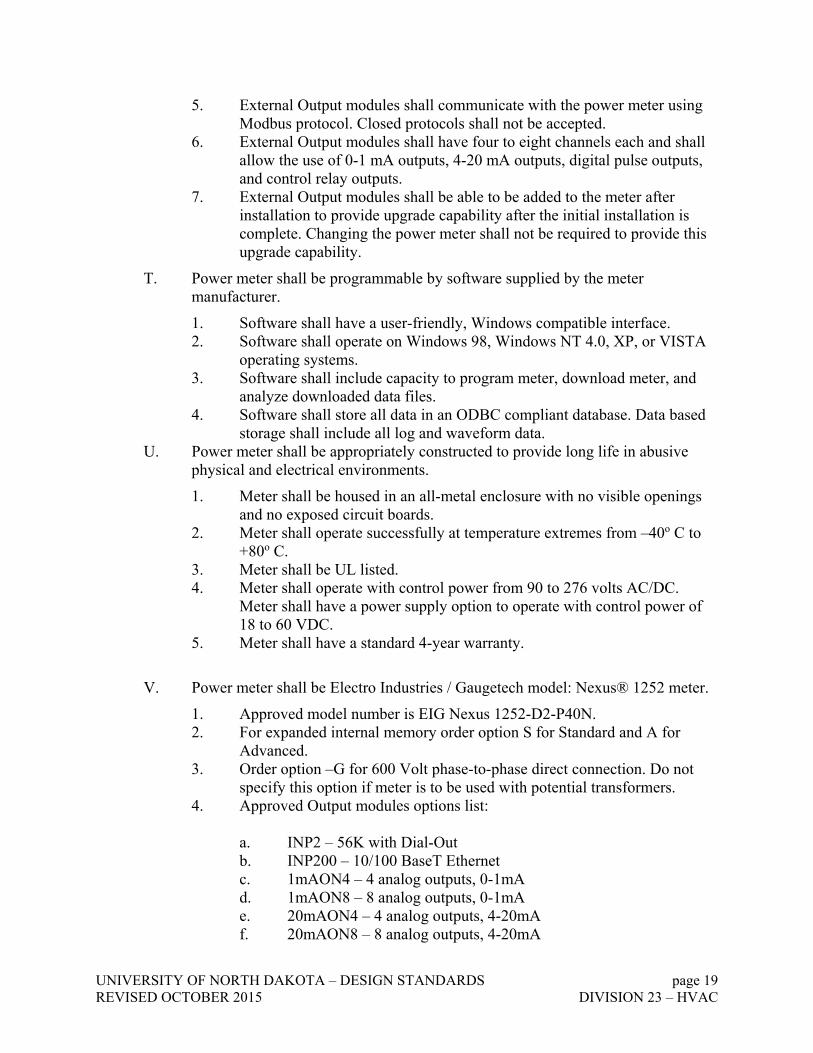
V. Power meter shall be Electro Industries / Gaugetech model: Nexus® 1252 meter.
1. Approved model number is EIG Nexus 1252-D2-P40N. 2. For expanded internal memory order option S for Standard and A for
Advanced. 3. Order option –G for 600 Volt phase-to-phase direct connection. Do not
specify this option if meter is to be used with potential transformers. 4. Approved Output modules options list:
a. INP2 – 56K with Dial-Out b. INP200 – 10/100 BaseT Ethernet c. 1mAON4 – 4 analog outputs, 0-1mA d. 1mAON8 – 8 analog outputs, 0-1mA e. 20mAON4 – 4 analog outputs, 4-20mA f. 20mAON8 – 8 analog outputs, 4-20mA

UNIVERSITY OF NORTH DAKOTA – DESIGN STANDARDS page 20 REVISED OCTOBER 2015 DIVISION 23 – HVAC
g. 4RO1 – 4 relay outputs h. 4PO1 – 4 solid state pulse outputs
i. MBIO – Output Module Mounting Bracket (must be ordered with purchase of Output Module)
j. PSI0 – Power Supply for additional 10 modules k. COMEXTS – Communicator EXT, single user l. COMEXT3 – Communicator EXT, multiple users m. AIEXT3 – PQ reporting package n. DISEXT – Dial-in server
6. For specification information, contact Electro Industries/GaugeTech at:
Electro Industries/GaugeTech 1800 Shames Drive Westbury, NY 11590 Phone: 516-334-0870
Fax: 516-338-4741
23 0533 – HEAT TRACING FOR HVAC PIPING 23 0548 – VIBRATION AND SEISMIC CONTROLS FOR HVAC PIPING AND EQUIPMENT 23 0553 – IDENTIFICATION FOR HVAC PIPING AND EQUIPMENT
A. GENERAL LABELLING
1. The contractor is to label the piping with text as to the loop function and loop medium. Similar as to what has normally been done for other buildings on campus (ex. Chilled Water Supply, Chilled Water Return, Glycol Hot Water Supply, etc.). In addition to the text labeling, if it is financially feasible within the project, please color code the exterior of the piping/insulation as to the process (ex. Steam, hot water, chilled water, domestic hot water, etc.).
2. Stencils – Black Paint 3. CHWR – Chilled Water Return 4. CHWS – Chilled Water Supply 5. STM-115 – 115 PSIG Steam 6. STM-60 – 60 PSIG Steam 7. STM-15 – 15 PSIG Steam 8. LP COND – Low Pressure Condensate Return 9. HP COND – High Pressure Condensate Return 10. HWR – Heating Water Return 11. HWS – Heating Water Supply 12. HWGLR – Heating Water Glycol Return 13. HWGLS – Heating Water Glycol Supply 14. HTRS – Heat Recovery Supply
UNIVERSITY OF NORTH DAKOTA – DESIGN STANDARDS page 21 REVISED OCTOBER 2015 DIVISION 23 – HVAC
15. HTRR – Heat Recovery Return 16. STORM – Storm Drain 17. DCW – Domestic Cold Water 18. DHW – Domestic Hot Water 19. DHWR – Domestic Hot Water Recirculation 20. GAS – Natural Gas 21. AIR – Compressed Air 22. OXYGEN – Oxygen 23. NITROGEN – Nitrogen 24. All building chillers are to be numbered sequentially. 25. All building cooling towers are to be numbered sequentially. 26. All building AHUs are to be numbered sequentially. Whether a unit is a MUA, H&V, RTU,
etc. it shall be labeled as an AHU and numbered consecutively throughout the building. If the project is adding on to or renovating an existing building, the contractor needs to contact Facilities Management for the next available system number so each mechanical system in the building is numbered in consecutive sequence and without duplication.
A. Valves shall be identified with a brass tag with brass ball-chain affixed to each valve indicating its enumeration and marked on the “As Built” as a legend which indicates what each numeral value serves accordingly. The legend will be provided to UND’s Preventative Maintenance Coordinator.
B. Valves that are hidden from view behind ceiling tiles/access panels shall be indicated with color coded round stickers placed as near to the valve location as possible on the ceiling grid/panels. Color codes shall be as Follows:
1. Dom Cold water: Blue dot 2. Dom Hot water: Green dot 3. Dom Hot recirc: Green dot 4. Natural Gas: Yellow dot 5. Compressed air: Black dot 6. Hot water heat: Orange dot 7. Steam/Condensate: Gray or Silver dot 8. Sprinkler: Red dot 9. Chilled water: Purple dot
C. Piping Identification:
1. Contents and direction of flow on all piping (steam, gas, water, condensate, etc.) shall be identified by labeling. a. Labels on piping up to 1-1/4" size shall be a minimum 1/2" high. b. Labels on piping larger than 1-1/4” size or pipe covering shall be a minimum of 1"
high. Labels shall be applied at all points where pipes pass through walls, at each change of direction and on each 20 feet of straight lengths.

UNIVERSITY OF NORTH DAKOTA – DESIGN STANDARDS page 22 REVISED OCTOBER 2015 DIVISION 23 – HVAC
23 0593 – TESTING, ADJUSTING AND BALANCING FOR HVAC
A. GENERAL PROCEDURES FOR TESTING AND BALANCING
1. Perform testing and balancing procedures on each system according to the procedures contained in AABC's "National Standards for Total System Balance", ASHRAE 111, NEBB's "Procedural Standards for Testing, Adjusting, and Balancing of Environmental Systems", SMACNA's "HVAC Systems - Testing, Adjusting, and Balancing".
2. All hydronics need to be air balanced according to NEEB requirements. 23 0713 – DUCT INSULATION A. INSULATION MATERIALS
1. Products shall not contain asbestos, lead, mercury, or mercury compounds.
2. Products that come in contact with stainless steel shall have a leachable chloride content of less than 50 ppm when tested according to ASTM C 871.
3. Insulation materials for use on austenitic stainless steel shall be qualified as acceptable according to ASTM C 795.
4. Foam insulation materials shall not use CFC or HCFC blowing agents in the manufacturing process.
5. Flexible Elastomeric Insulation: Closed-cell, sponge- or expanded-rubber materials. Comply with ASTM C 534, Type II for sheet materials.
6. Mineral-Fiber Blanket Insulation: Mineral or glass fibers bonded with a thermosetting resin. Comply with ASTM C 553, Type II and ASTM C 1290, Type I, Type II with factory-applied vinyl jacket, Type III with factory-applied FSK jacket, Type III with factory-applied FSP jacket.
7. Mineral-Fiber Board Insulation: Comply with ASTM C 612, Type IA or Type IB. For duct and plenum applications, provide insulation without factory-applied jacket or with factory-applied ASJ with factory-applied FSK jacket.
8. Mineral-Fiber, Pipe and Tank Insulation: Semi rigid board material with factory-applied ASJ or FSK jacket complying with ASTM C 1393, Type II or Type IIIA Category 2, or with properties similar to ASTM C 612, Type IB.
9. Polyolefin: Unicellular, polyethylene thermal plastic insulation. Comply with ASTM C 534 or ASTM C 1427, Type I, Grade 1 for tubular materials and Type II, Grade 1 for sheet materials.
B. FIRE-RATED INSULATION SYSTEMS
1. Comply with ASTM C 656, Type II, Grade 6. Tested and certified to provide a [1] [2]-hour fire rating by an NRTL acceptable to authorities having jurisdiction.

UNIVERSITY OF NORTH DAKOTA – DESIGN STANDARDS page 23 REVISED OCTOBER 2015 DIVISION 23 – HVAC
2. Our preference is to have the exterior of the duct wrapped with minimum 1 ½” Owens Corning foil wrapped insulation. The interior of the duct should not be lined. (We have had problems with duct liner in the past. Duct liner holds dirt and is not good for maintaining indoor air quality. It also dries out over time and causes problems down the road. We have had problems with particles of the duct liner flaking off and getting into the air stream. No duct liner; only wrapped is the preference.
23 0716 – HVAC EQUIPMENT INSULATION
A. INSULATION MATERIALS
1. Comply with requirements in "Breeching Insulation Schedule" and "Equipment Insulation Schedule" articles for where insulating materials shall be applied.
2. Heat exchanger, chiller, loop piping and associated hydronic components shall be insulated with
minimum 1 1/2” fiberglass insulation. Areas that are outside or susceptible to wear and tear from service access should be covered with aluminum or PVC chiller’s jacket to protect the integrity of the insulation. Valves, steam traps, condensate tanks, etc. that would need to be accessed for service are to have removable blankets installed.
23 0719 – HVAC PIPING INSULATION
A. Steam Heating Piping Insulation
1. All steam lines, steam condensate lines, and flash tanks shall be insulated with glass fiber pipe insulation in one piece molded section, 4 lb. nominal density, and of the following thickness:
Application Pipe Size Insulation Thickness 2’’ and less 1-1/2’’ Steam lines (Low Pressure) 2-1/2’’ – 4’’ 2’’ 201°F - 250°F 5’’ – 6’’ 2-1/2’’ 8’’ and over 3’’ 1’’ and less 1-1/2’’ 1-1/4’’ – 2’’ 2’’ Steam lines (Medium 2-1/2’’ – 4’’ 2-1/2’’ Pressure) 251°F - 305°F 5’’ – 6’’ 3’’ 8’’ and over 3-1/2’’ 1’’ and less 2’’ 1-1/4’’ – 2’’ 2-1/2’’ Steam lines (High Pressure) 2-1/2’’ – 4’’ 3’’ 306°F - 460°F 5’’ – 6’’ 3-1/2’’ 8’’ and over 4’’ total thickness 1’’ and less 1’’ Condensate lines 1-1/4’’ – 2’’ 1-1/2’’ 2-1/2’’ and over 2’’ Flash Tanks All 2’’

UNIVERSITY OF NORTH DAKOTA – DESIGN STANDARDS page 24 REVISED OCTOBER 2015 DIVISION 23 – HVAC
B. Steam and condensate piping in areas prone to flooding, such as steam vaults, shall be piped using “Foam Glass” wrapped in a metal jacket.
C. For High Temperature Equipment Insulation for equipment inside the building in conventional equipment rooms the following shall apply:
a. All steam valves including control valves, expansion joints and the access end of strainers shall be covered with a custom fabricated insulation jacket secured around the fitting. Insulation Systems will be custom designed and engineered for each individual item which is not a standard product based on type of application, operating temperature, and environment. A close contour fit is essential for proper thermal performance and neat appearance.
b. Insulation Jacket shall be constructed of Teflon Impregnated Fiberglass Cloth with a minimum temperature rating to 500F and Dark Grey in color. Insulation shall be a minimum of one (1”) Inch Thick.
c. Insulation jacket shall be secured to the fitting with stainless steel buckle and strap assembly, Grey color, Maximum Temperature Resistance 250°. Insulation Seams which do not tightly butt one another are Not Acceptable.
d. All reusable insulation blanket assemblies shall be labeled with laser label. The tagging systems will facilitate installation and reinstallation of all blankets and enable the manufacturer to provide replacements upon request by number assigned as imprinted on the label.
23 0800 – COMMISSIONING OF HVAC 23 0913 – INSTRUMENTATION AND CONTROL DEVICES FOR HVAC 23 0923 – DIRECT-DIGITAL CONTROLS FOR HVAC 23 0943 – PNEUMATIC CONTROL SYSTEM FOR HVAC 23 0993 – SEQUENCE OF OPERATION FOR HVAC CONTROLS 23 1113 –FACILITY FUEL-OIL PIPING
D. SYSTEM DESCRIPTION
1. Electrical Components, Devices, and Accessories: Listed and labeled as defined in NFPA 70, by a qualified testing agency, and marked for intended location and application.

UNIVERSITY OF NORTH DAKOTA – DESIGN STANDARDS page 25 REVISED OCTOBER 2015 DIVISION 23 – HVAC
2. Comply with ASME B31.9, "Building Services Piping," for fuel-oil piping materials, installation, testing, and inspecting.
3. Fuel-Oil Valves: Comply with UL 842 and have service mark initials "WOG" permanently marked on valve body.
4. Comply with requirements of the EPA and of state and local authorities having jurisdiction. Include recording of fuel-oil piping.
E. PERFORMANCE REQUIREMENTS
1. Maximum Operating-Pressure Ratings: 3-psig (21-kPa) fuel-oil supply pressure at oil-fired appliances.
23 2113.33 –GROUND LOOP HEAT-PUMP PIPING
A. PIPES AND FITTINGS
1. Manufacturers:
Centennial Plastics, Inc. Chevron-Phillips Chemical Company; Performance Pipe Division.
B. HORIZONTAL AND VERTICAL PIPING INSTALLATION
1. Separate trenches by 10 feet minimum unless otherwise indicated. Remove rocks in trenches that could contact pipe.
2. Backfill 3. Extend pipe from trench onto bottom of body of water at an elevation that is at least 12 inches
below frost line. Seal membrane or impervious liner under body of water after installing piping. 4. Install HDPE piping in trenches according to ASTM D 2774 or ASTM F 645. 5. Clean HDPE pipe and fittings and make heat-fusion joints according to ASTM D 2657.
Minimize number of joints. 6. Purge, flush, and pressure test piping before backfilling trenches and boreholes. 7. Install continuous detectable warning tape for underground piping. Locate tape a minimum of
24 inches below finished grade, directly over piping. 8. Install HDPE piping in boreholes according to ASTM D 2774 or ASTM F 645. 9. Completely fill the borehole from bottom to top with backfill material. 10. Install the header piping 4 to 6 inches deep and install the horizontal piping from the header to
the boreholes. 11. Extend the horizontal piping and connect to ground-loop heat-pump piping systems at outside
face of building wall in locations and pipe sizes indicated. 23 2113 – HYDRONIC PIPING

UNIVERSITY OF NORTH DAKOTA – DESIGN STANDARDS page 26 REVISED OCTOBER 2015 DIVISION 23 – HVAC
A. COPPER TUBE AND FITTINGS
1. Drawn-Temper Copper Tubing: ASTM B 88, Type L ASTM B 88.
2. Annealed-Temper Copper Tubing: ASTM B 88, Type K.
3. DWV Copper Tubing: ASTM B 306, Type DWV.
4. Grooved, Mechanical-Joint, Wrought-Copper Fittings: ASME B16.22.
Manufacturers: Subject to compliance with requirements, provide products by one of the following :
Anvil International, Inc. Star Pipe Products. Victaulic Company.
Grooved-End Copper Fittings: ASTM B 75, copper tube or ASTM B 584, bronze casting. Grooved-End-Tube Couplings: Rigid pattern unless otherwise indicated; gasketed fitting.
Ductile-iron housing with keys matching pipe and fitting grooves, pre-lubricated EPDM gasket rated for minimum 230 deg F for use with housing, and steel bolts and nuts.
Copper or Bronze Pressure-Seal Fittings:
a. Manufacturers: Subject to compliance with requirements, provide products by one of the following:
NIBCO INC. Viega.
Housing: Copper. O-Rings and Pipe Stops: EPDM. Tools: Manufacturer's special tools. Minimum 200-psig working-pressure rating at 250 deg F.
Wrought-Copper Unions: ASME B16.22.
B. STEEL PIPE AND FITTINGS
2. Steel Pipe: ASTMA 53/A 53M, black steel with plain ends; welded and seamless, Grade B, and wall thickness as indicated in "Piping Applications" Article.
Cast-Iron Threaded Fittings: ASME B16.4; Classes 125 and 250 as indicated in "Piping Applications" Article. Malleable-Iron Threaded Fittings: ASME B16.3, Classes 150 and 300 as indicated in "Piping Applications" Article. Malleable-Iron Unions: ASME B16.39; Classes 150, 250, and 300 as indicated in "Piping Applications" Article. Cast-Iron Pipe Flanges and Flanged Fittings: ASME B16.1, Classes 25, 125, and 250; raised ground face, and bolt holes’ spot faced as indicated in "Piping Applications" Article. Wrought-Steel Fittings: ASTM A 234/A 234M, wall thickness to match adjoining pipe. Wrought Cast- and Forged-Steel Flanges and Flanged Fittings: ASME B16.5, including bolts, nuts, and gaskets of the following material group, end connections, and facings:

UNIVERSITY OF NORTH DAKOTA – DESIGN STANDARDS page 27 REVISED OCTOBER 2015 DIVISION 23 – HVAC
Material Group: 1.1. End Connections: Butt welding. Facings: Raised face.
Grooved Mechanical-Joint Fittings and Couplings:
Manufacturers: Subject to compliance with requirements, provide products by one of the following:
Anvil International, Inc. Central Sprinkler Company. Star Pipe Products. Victaulic Company.
C. The hydronics loop and associated equipment will need to be clean. The hydronics loop will
need to be air tested for leaks and then flushed. If new coils connected to the loop are ensured to be clean, they should be bypassed during the flushing process. After flushing, the loop will need to be tested by a third party (with sampling witnessed by the engineer or UND) before being accepted and connecting to the new coils. A copy of the report needs to be provided to UND.
D. Hydronics piping material shall be soldered, threaded or welded. Victaulic piping will be accepted only if it is warrantied for a minimum of 10 years (prefer 15 years). (We have had problems with grooved piping leaking in the past. Usually two things lead to leaks, improper material or improper installation). If the contractor installs Victaulic, they need to ensure they use the proper seals for the medium and the failure temperatures of the loop. The contractor needs to follow the manufacturer’s installation process in order for Victaulic to warranty it. Most importantly, the contractor needs to have a trained installer and have it inspected by a Victaulic rep (see Victaulic’s spec sections 3.01 B.1 and C.1 for specific details). If they follow the process in the Victaulic specification, then Victaulic will warranty it. For hydronic HVAC systems, Pro-Press or crimped connections are not to be used; we have had problems with those in the past. For under floor hydronic radiation heating systems, PEX or Kytech products are acceptable.
E. Each loop shall include a holding tank, pump, pot feeder, and valves to add fluid to the system and to drain the system. The relief for the overflow shall drain into the holding tank to keep all fluid within the system. Side stream filters shall be installed for chilled water, hot water, and heat pump loops. Spirotherm air eliminator vents shall be used on all loops where necessary
23 2114 – HYDRONIC SPECIALTIES
A. Gate valves are preferred over butterfly valves where major portions of a hydronic system may need to be isolated, such as pumps. All valves used for isolation of systems, shut-offs or for servicing equipment shall be gate or ball valves. Butterfly valves are acceptable for balancing or flushing purposes.
B. All hydronic valves 3” or smaller shall be ball-valves made of brass or better quality materials. C. All hydronic valves over 3” or steam valves shall be gate valves made of cast iron or better
quality materials. Valve stems are to have grease zerks to lubricate the stem in order to open and close the valve easily. Butterfly valves or other types of valves could be considered for isolation if they can be demonstrated to have zero leakage. A 10-year warranty is preferred for valves.

UNIVERSITY OF NORTH DAKOTA – DESIGN STANDARDS page 28 REVISED OCTOBER 2015 DIVISION 23 – HVAC
23 2123 – HYDRONIC PUMPS
CLOSE-COUPLED, IN-LINE CENTRIFUGAL PUMPS
Manufacturers:
Bell & Gossett; Div. of ITT Industries. Armstrong.
Description: Factory assembled and -tested, centrifugal, overhung-impeller, close-coupled, in-line pump as defined in HI 1.1-1. 2 and HI 1.3; designed for installation with pump and motor shafts mounted horizontally or vertically. Rate pump for 125-psig minimum working pressure and a continuous water temperature of 200 degrees Fahrenheit.
Pump Construction:
a. Casing: Radially split, cast iron, with threaded gage tapping’s at inlet and outlet, and threaded companion-flange connections.
Impeller: ASTM 8 584, cast bronze; statically and dynamically balanced, keyed to shaft, and secured with a locking cap screw. Trim impeller to match specified performance.
Pump Shaft: Steel, with copper-alloy shaft sleeve. Mechanical Seal: Carbon rotating ring against a ceramic seat held by a stainless-steel spring,
and Buna-N bellows and gasket. Include water slinger on shaft between motor and seal. Packing Seal: Stuffing box, with a minimum of four rings of graphite-impregnated braided yarn
with bronze lantern ring between center two graphite rings, and bronze packing gland. Pump Bearings: Permanently lubricated ball bearings. Motor: Single speed, with permanently lubricated ball bearings, unless otherwise indicated; and
rigidly mounted to pump casing.
Capacities and Characteristics:
a. Reference Mechanical Schedule Sheet.
CLOSE-COUPLED, END-SUCTION CENTRIFUGAL PUMPS
1. Manufacturers:
a. Bell & Gossett; Div. of ITT Industries.
Description: Factory-assembled and -tested, centrifugal, overhung-impeller, close-coupled, end-suction pump as defined in HI 1.1-1.2 and HI 1.3; designed for installation with pump and motor shafts mounted horizontally. Rate pump for 125-psig minimum working pressure and a continuous water temperature of 225 oF.
PUMP CONSTRUCTION:
1. Casing: Radially split, cast iron, with replaceable bronze wear rings, drain plug at bottom and air vent at top of volute, threaded gage tapping’s at inlet and outlet, and threaded companion-flange connections.
Impeller: ASTM B 584, cast bronze; statically and dynamically balanced, keyed to shaft, and secured with a locking cap screw. Tri m impeller to match specified performance.

UNIVERSITY OF NORTH DAKOTA – DESIGN STANDARDS page 29 REVISED OCTOBER 2015 DIVISION 23 – HVAC
Pump Shaft: Steel, with copper-alloy shaft sleeve. Mechanical Seal: Carbon rotating ring against a ceramic seat held by a stainless-steel spring, and
Buna-N bellows and gasket. Include water slinger on shaft between motor and seal. Pump Bearings: Permanently lubricated ball bearings. Motor: Single speed, with permanently lubricated ball bearings, unless otherwise indicated; rigidly
mounted to pump casing with integral pump support. 27. Circulating pumps shall be B&G (Bell and Gossett), Armstrong or other as approved by
Facilities Management. Other pumps of equivalent quality will be considered, but no Taco or Dunham Bush pumps will be accepted due to previous maintenance problems with those brands.
28. Preference is to have variable frequency drives on pumps where feasible. See ‘Variable Frequency Drives’.
29. Complete a hydronics balance of all hydronic systems, following NEBB regulations. 30. Circulating pumps stall be setup to have a lag pump for hot water, chilled water, condenser
water, heat pump loop and whenever feasible for all other applicable systems. Add lead/lag control of the pumps through the automation system.
31. For heating glycol loops, 40% SR1 Dowtherm glycol shall be used and for chilled glycol loops 30% SR1 Dowtherm glycol shall be used, unless otherwise approved by Facilities Management. If the engineer calculates a higher percentage is recommended to prevent freeze-ups, please bring that forward to Facilities Management for approval. We try to keep our glycol systems consistent whenever possible.
23 2213 – STEAM AND CONDENSATE HEATING PIPING
A. High pressure steam and condensate valves shall be Class 150 SWP cast steel and stamped for high pressure steam application.
1. Flange valves OS & Y (required for 2” and larger, optional for 1-1/2” and
smaller) shall be Crane, Velan or approved equal. 2. Threaded valves 1-1/2” and smaller shall be 800# forged steel, rising stem, bolted
bonnet
B. Owner may require the Contractor to verify and assure the quality of all steam pipe welds by performing x-ray testing on 10 percent of all welded connections as determined by Owner.
1. If failures are detected, Owner reserves right to have all welded connections
inspected.
C. Provide a clear access to all valves.
D. Install pressure regulators with manual bypasses at mechanical entrances of high pressure steam distribution lines.
1. Use parallel pressure reducing stations where large fluctuations in steam use is anticipated or where steam use is critical.

UNIVERSITY OF NORTH DAKOTA – DESIGN STANDARDS page 30 REVISED OCTOBER 2015 DIVISION 23 – HVAC
E. Duplex electric condensate pumps with sight glass. F. Install drip traps before all thermostatic temperature regulating valves and pressure reducing
valves, and at line's end. G. Install strainer upstream from all steam traps. Strainer to be fitted with manual blow-down valve. H. Consult with the Owner concerning the installation of a tunnel or direct buried systems. I. High pressure steam valves shall be Class 150 cast steel and stamped for high-pressure steam
application. J. Direct buried steam and condensate systems:
1. Direct buried systems shall be supplied by Perma-Pipe. 2. All steam pipe connections shall be welded; all welders must be certified.
K. Cathodic protection should be installed where necessary to protect the steam distribution system from corrosion.
L. Contractor shall verify and assure the quality of all steam pipe welds by performing x-ray or hydro testing of all welded connections. Verified by third party.
M. Provide a clear access to shut-off valves. N. Install Spence Type "E", Boylston or Leslie pressure regulators with bypasses at mechanical
entrances of high pressure distribution lines. O. Install Spence Type "E", Boylston or Leslie pressure regulators with bypasses at mechanical
entrances of high pressure distribution lines. Use cascading or step pressure operated parallel pressure reducing stations where large fluctuation in steam use is anticipated. Individual PRV's for each item of equipment are not satisfactory. Pipe the reduced pressure steam from the reduced pressure header to the items of equipment, utilizing proportional pneumatic steam control valves that have positive shut-off, fail-to-open, temperature control of medium being heated. Condensate pumps shall be non-electric positive displacement pressure-powered pumps for larger applications. Provide removable insulating jacket for the pump tank and valves. Install drip traps before all thermostatic temperature regulating valves and pressure reducing valves, and at line's end. l. Install removable insulated covers on steam reducing stations for maintenance. The
removable cover should be able to be re-installed after repairs. 23 2214 –STEAM AND CONDENSATE HEATING SPECIALTIES
F. VALVES
1. Gate, Globe, Check, Ball, and Butterfly Valves:
2. Stop-Check Valves:
a. Manufacturers:
1) A.Y. McDonald Mfg. Co. 2) Cincinnati Valve Company. 3) Crane; Crane Energy Flow Solutions. 4) Jenkins Valves.

UNIVERSITY OF NORTH DAKOTA – DESIGN STANDARDS page 31 REVISED OCTOBER 2015 DIVISION 23 – HVAC
G. SAFETY VALVES
1. Bronze or Brass Safety Valves: ASME labeled.
a. Manufacturers:
1) Armstrong International, Inc. 2) Kunkle Valve. 3) Spirax Sarco, Inc.
2. Cast-Iron Safety Valves: ASME labeled.
a. Manufacturers:
1) Armstrong International, Inc. 2) Kunkle Valve. 3) Spirax Sarco, Inc.
H. PRESSURE-REDUCING VALVES
1. Manufacturers:
a. Boylston
b. Watts c. Spence Engineering Company, Inc.
I. STEAM TRAPS
a. Manufacturers: Subject to compliance with requirements, provide products by one of the following:
1) Armstrong International, Inc. 2) Velan 3) Gestra 4) Hoffman
J. THERMOSTATIC AIR VENTS AND VACUUM BREAKERS
1. Thermostatic Air Vents:
a. Manufacturers:
1) Armstrong International, Inc. 2) Barnes & Jones, Inc. 3) Dunham-Bush, Inc. 4) Hoffman Specialty.

UNIVERSITY OF NORTH DAKOTA – DESIGN STANDARDS page 32 REVISED OCTOBER 2015 DIVISION 23 – HVAC
5) Spirax Sarco, Inc.
2. Vacuum Breakers:
a. Manufacturers:
1) Armstrong International, Inc. 2) Dunham-Bush, Inc. 3) Hoffman Specialty.
23 2300 –REFRIGERANT PIPING
A. PERFORMANCE REQUIREMENTS 1. Line Test Pressure for Refrigerant R-134a 2. Refrigerant tubing shall be type “k” hard copper 3. Suction Lines for Air-Conditioning Applications: 115 psig. 4. Suction Lines for Heat-Pump Applications: 225 psig. 5. Hot-Gas and Liquid Lines: 225 psig.
6. Line Test Pressure for Refrigerant R-407C:
a. Suction Lines for Air-Conditioning Applications: 230 psig.
b. Suction lines for Heat pump applications 380 psig
c. Hot gas liquid lines: 380 psig
Line Test Pressure for Refrigerant R-410A:
a. Suction Lines for Air-Conditioning Applications: 300 psig. Suction Lines for Heat-Pump Applications: 535 psig. Hot-Gas and Liquid Lines: 535 psig.
23 2500 – HVAC WATER TREATMENT
1. Water quality for HVAC systems shall minimize corrosion, scale buildup, and biological growth for optimum efficiency of HVAC equipment without creating a hazard to operating personnel or to the environment.
2. Base HVAC water treatment on quality of water available at Project site, HVAC system equipment material characteristics and functional performance characteristics, operating personnel capabilities, and requirements and guidelines of authorities having jurisdiction. Specify dowtherm SRI (ethylene glycol) or dowfrost (propylene glycol) distilled or R/O water shall be used in closed loop heating systems
23 3100 –HVAC DUCTS AND CASINGS

UNIVERSITY OF NORTH DAKOTA – DESIGN STANDARDS page 33 REVISED OCTOBER 2015 DIVISION 23 – HVAC
A. SINGLE-WALL RECTANGULAR, ROUND, FLAT-OVAL DUCTS AND FITTINGS
1. General Fabrication Requirements: Comply with SMACNA's "HVAC Duct Construction Standards - Metal and Flexible" based on indicated static-pressure class unless otherwise indicated.
2. Transverse Joints: Select joint types and fabricate according to SMACNA's "HVAC Duct Construction Standards - Metal and Flexible," Figure 2-1, "Rectangular Duct/Transverse Joints," for static-pressure class, applicable sealing requirements, materials involved, duct-support intervals, and other provisions in SMACNA's "HVAC Duct Construction Standards - Metal and Flexible."
3. Longitudinal Seams: Select seam types and fabricate according to SMACNA's "HVAC Duct Construction Standards - Metal and Flexible," Figure 2-2, "Rectangular Duct/Longitudinal Seams," for static-pressure class, applicable sealing requirements, materials involved, duct-support intervals, and other provisions in SMACNA's "HVAC Duct Construction Standards - Metal and Flexible."
4. Elbows, Transitions, Offsets, Branch Connections, and Other Duct Construction: Select types and fabricate according to SMACNA's "HVAC Duct Construction Standards - Metal and Flexible," Chapter 4, "Fittings and Other Construction," for static-pressure class, applicable sealing requirements, materials involved, duct-support intervals, and other provisions in SMACNA's "HVAC Duct Construction Standards - Metal and Flexible."
5. If necessary, sound attenuators are fine. Facilities Management is open to recommendations to improve HVAC affected acoustics
6. Flat-Oval Ducts: Indicated dimensions are the duct width (major dimension) and diameter of the round sides connecting the flat portions of the duct (minor dimension).
B. DOUBLE-WALL RECTANGULAR, ROUND, FALT-OVAL DUCTS AND FITTINGS
1. Manufacturers: Subject to compliance with requirements, provide products by one of the following:
a. McGill AirFlow LLC. b. MKT Metal Manufacturing. c. Linx Industries
2. Rectangular Ducts: Fabricate ducts with indicated dimensions for the inner duct.
3. Outer Duct: Comply with SMACNA's "HVAC Duct Construction Standards - Metal and Flexible" based on indicated static-pressure class unless otherwise indicated.
4. Transverse Joints: Select joint types and fabricate according to SMACNA's "HVAC Duct Construction Standards - Metal and Flexible," Figure 2-1, "Rectangular Duct/Transverse Joints," for static-pressure class, applicable sealing requirements, materials involved, duct-support intervals, and other provisions in SMACNA's "HVAC Duct Construction Standards - Metal and Flexible."
5. Longitudinal Seams: Select seam types and fabricate according to SMACNA's "HVAC Duct Construction Standards - Metal and Flexible," Figure 2-2, "Rectangular Duct/Longitudinal Seams," for static-pressure class, applicable sealing requirements, materials involved, duct-support intervals, and other provisions in SMACNA's "HVAC Duct Construction Standards - Metal and Flexible."

UNIVERSITY OF NORTH DAKOTA – DESIGN STANDARDS page 34 REVISED OCTOBER 2015 DIVISION 23 – HVAC
6. Interstitial Insulation: Fibrous-glass liner complying with ASTM C 1071, NFPA 90A, or NFPA 90B; and with NAIMA AH124, "Fibrous Glass Duct Liner Standard."
a. Maximum Thermal Conductivity: 0.27 Btu x in./h x sq. ft. x deg F b. Install spacers that position the inner duct at uniform distance from outer duct without
compressing insulation. c. Coat insulation with antimicrobial coating. d. Cover insulation with polyester film complying with UL 181, Class 1.
7. Interstitial Insulation: Flexible elastomeric duct liner complying with ASTM C 534, Type II for sheet materials, and with NFPA 90A or NFPA 90B.
a. Maximum Thermal Conductivity: [0.25 Btu x in./h x sq. ft. x deg F (0.034 W/m x K)] <Insert conductivity> at 75 deg F (24 deg C) mean temperature.
8. Inner Duct: Minimum 0.028-inch [perforated galvanized sheet steel having 3/32-inch diameter perforations, with overall open area of 23 percent solid sheet steel.
9. Formed-on Transverse Joints (Flanges): Select joint types and fabricate according to SMACNA's "HVAC Duct Construction Standards - Metal and Flexible," Figure 2-1, "Rectangular Duct/Traverse Joints," for static-pressure class, applicable sealing requirements, materials involved, duct-support intervals, and other provisions in SMACNA's "HVAC Duct Construction Standards - Metal and Flexible."
10. Longitudinal Seams: Select seam types and fabricate according to SMACNA's "HVAC Duct Construction Standards - Metal and Flexible," Figure 2-2, "Rectangular Duct/Longitudinal Seams," for static-pressure class, applicable sealing requirements, materials involved, duct-support intervals, and other provisions in SMACNA's "HVAC Duct Construction Standards - Metal and Flexible."
11. Flat-Oval Ducts: Indicated dimensions are the duct width (major dimension) and diameter of the round sides connecting the flat portions of the duct (minor dimension) of the inner duct.
C. GENERAL CASING FABRICATION REQUIREMENTS
1. General Material Requirements: Comply with SMACNA's "HVAC Duct Construction Standards - Metal and Flexible," Chapter 9, "Equipment and Casings," for acceptable materials, material thicknesses, and casing construction methods unless otherwise indicated. Sheet metal materials shall be free of pitting, seam marks, roller marks, stains, discolorations, and other imperfections.
2. Galvanized Sheet Steel: Comply with ASTM A 653/A 653M.
a. Exterior Surface Galvanized Coating Designation: G60, Z180, G90, Z275. b. Interior Surface Galvanized Coating Designation:
1) Sections Not Exposed to Moisture: G60 Z180)] [G90 (Z275)]. 2) Sections Housing and Downstream from Cooling Coil and Humidifiers: [G90
(Z275)].
3. Stainless Steel: ASTM A 480/A 480M, [Type 304] [Type 316], and having a[ No. 2D] <Insert finish> finish.

UNIVERSITY OF NORTH DAKOTA – DESIGN STANDARDS page 35 REVISED OCTOBER 2015 DIVISION 23 – HVAC
4. Sealing Requirement: SMACNA's "HVAC Duct Construction Standards - Metal and Flexible," Seal Class A. Seal all seams, joints, connections, and abutments to building.
5. Penetrations: Seal all penetrations airtight. Cover with escutcheons and gaskets, or fill with suitable compound so there is no exposed insulation. Comply with requirements for escutcheons specified in Section 230518 "Escutcheons for HVAC Piping." Provide shaft seals where fan shafts penetrate casing.
6. Access Doors: Fabricate access doors according to SMACNA's "HVAC Duct Construction Standards - Metal and Flexible," Figure 9-15, "Casing Access Doors - 2-inch wg (500 Pa)," and Figure 9-16, "Casing Access Doors - 3-10-inch wg (750-2500 Pa)"; and according to pressure class of the plenum or casing section in which access doors are to be installed.
7. Condensate Drain Pans: Formed sections of Type 304, stainless-steel sheet G90, Z275 coated, galvanized sheet steel complying with requirements in ASHRAE 62.1. Pans shall extend a minimum of 12 inches (300 mm) past coil.
23 3300 –AIR DUCT ACCESSORIES
1. All Ahu’s shall have insulated airfoil aluminum ultra-low leak dampers 2. If necessary, sound attenuators are fine. Facilities Management is open to recommendations to
improve HVAC affected acoustics. 23 3319 –DUCT SILENCERS 1. If necessary, sound attenuators are fine. Facilities Management is open to recommendations to
improve HVAC affected acoustics. 23 3413 – AXIAL HVAC FANS 23 3416 – CENTRIFUGAL HVAC FANS 23 3423 – HVAC POWER VENTILATORS
A. UTILITY SET FANS
1. Manufacturers:
a. Aerovent; a division of Twin City Fan Companies, Ltd. b. Carnes Company. c. Loren Cook Company. d. Peerless Blowers.

UNIVERSITY OF NORTH DAKOTA – DESIGN STANDARDS page 36 REVISED OCTOBER 2015 DIVISION 23 – HVAC
B. CENTRIFUGAL ROOF VENTILATORS
1. Manufacturers:
a. Acme Engineering & Manufacturing Corp. b. Aerovent; a division of Twin City Fan Companies, Ltd. c. Carnes Company. d. Greenheck Fan Corporation. e. Loren Cook Company. f. PennBarry.
C. AXIAL ROOF VENTILATORS
1. Manufacturers:
a. Acme Engineering & Manufacturing Corp. b. Aerovent; a division of Twin City Fan Companies, Ltd. c. Broan-NuTone LLC. d. Carnes Company. e. Greenheck Fan Corporation. f. Loren Cook Company.
D. UPBLAST PROPELLER ROOF EXHAUST FANS
1. Manufacturers:
a. Acme Engineering & Manufacturing Corp. b. Aerovent; a division of Twin City Fan Companies, Ltd. c. Carnes Company. d. Greenheck Fan Corporation. e. Loren Cook Company.
E. CENTRIFUGAL WALL VENTILATORS
1. Manufacturers:
a. Acme Engineering & Manufacturing Corp. b. Aerovent; a division of Twin City Fan Companies, Ltd. c. Broan-NuTone LLC. d. Carnes Company. e. Greenheck Fan Corporation. f. Loren Cook Company.
F. CEILING-MOUNTED VENTILATORS
1. Manufacturers:
a. Broan-NuTone LLC.

UNIVERSITY OF NORTH DAKOTA – DESIGN STANDARDS page 37 REVISED OCTOBER 2015 DIVISION 23 – HVAC
b. Carnes Company. c. Greenheck Fan Corporation. d. JencoFan. e. Loren Cook Company.
G. IN-LINE CENTRIFUGAL FANS
1. Manufacturers:
a. Acme Engineering & Manufacturing Corp. b. Carnes Company. c. FloAire. d. Greenheck Fan Corporation. e. JencoFan. f. Loren Cook Company.
H. PROPELLER FANS
1. Manufacturers:
a. Acme Engineering & Manufacturing Corp. b. Airmaster Fan Company. c. Broan-NuTone LLC. d. Carnes Company. e. Chicago Blower Corporation. f. Cincinnati Fan.
23 3433 – AIR CURTAINS
A. AIR-CURTAIN UNIT
1. Manufacturers:
a. Air Economy Corporation. b. Cambridge Engineering, Inc. c. Fantech. d. Loren Cook Company. e. Marley Engineered Products. f. Mars Air Doors; Mars Air Systems. g. Mestek, Inc. h. Powered Aire, Inc.
23 3514 – DUST COLLECTIONS 23 3516 – ENGINE EXHAUST SYSTEMS

UNIVERSITY OF NORTH DAKOTA – DESIGN STANDARDS page 38 REVISED OCTOBER 2015 DIVISION 23 – HVAC
23 3600 – AIR TERMINAL UNITS
A. Any new VAVs shall be blade type Titus, Trane or Price. VAVs shall have reheats and access panels on the inlet side of the reheat coil with enough room to access the coil to clean it. Isolation valves need to be installed to isolate reheat coils. Facilities Management prefers VAVs in equipment rooms when possible, especially for laboratories and critical areas. VAVs shall be numbered consecutively within the building
B. All Ahu’s shall have insulated airfoil aluminum ultra-low leak dampers.
C. All actuators shall be electronic. 23 3700 – AIR OUTLETS AND INLETS 23 3813 – COMMERCIAL-KITCHEN HOODS
A. TYPE I EXHAUST HOOD FABRICATION
1. Manufacturers:
Captive-Aire Systems. Greenheck Fan Corporation.
B. TYPE II EXHAUST HOOD FABRICATION
1. Manufacturers:
Captive-Aire Systems. Greenheck Fan Corporation.
23 4000 – HVAC AIR CLEANING DEVICES 23 5100 – BREECHINGS, CHIMNEYS AND STACKS 23 5213 – ELECTRIC BOILERS
C. MANUFACTURERS
1. Manufacturers: Steam/Hot Water
a. Cleaver-Brooks. b. Fulton Boiler Works, Inc. c. Lochinvar, LLC. d. Precision Boilers, LLC.

UNIVERSITY OF NORTH DAKOTA – DESIGN STANDARDS page 39 REVISED OCTOBER 2015 DIVISION 23 – HVAC
e. PVI Industries, LLC. 23 5216 – CONDENSING BOILERS 23 5223 – CAST IRON BOILERS 23 5233.13 – FINNED WATER TUBE BOILERS 23 5233.16 – STEEL WATER TUBE BOILERS 23 5239.13 – SCOTCH MARINE BOILERS 23 5400 – FURNACES 23 5533 – FUEL FIRED UNIT HEATERS 23 5613.13 – HEATING SOLAR FLAT PLATE COLLECTORS 23 5700 – HEAT EXCHANGERS FOR HVAC
D. All building heat exchangers (convertors) are to be numbered sequentially.
E. Building heating systems shall all be hydronic. No steam direct AHU coils, reheat coils, radiation, etc. will be accepted.
F. Heat exchangers shall be specified as Bell and Gossett (B&G), Weil McLain, or Rheem.
G. Tube and shell or plate to plate heat exchangers/convertors will be accepted.
23 6100 – REFRIGERANT COMPRESSORS 23 6213 – PACKAGED AIR-COOLED REFRIGERANT COMPRESSOR AND
CONDENSER UNITS 23 6313 – AIR COOLED REFRIGERANT CONDENSERS

UNIVERSITY OF NORTH DAKOTA – DESIGN STANDARDS page 40 REVISED OCTOBER 2015 DIVISION 23 – HVAC
A. MANUFACTURERS
1. Manufacturers: Subject to compliance with requirements, provide products by one of the following:
Carrier Corporation; a unit of United Technologies Corp. Trane York Daikin
23 6413 – ABSORPTION WATER CHILLERS
1. Absorption Chillers will not be accepted 23 6416 – CENTRIFUGAL WATER CHILLERS
1. Normally buildings are setup to house their own chiller or DX systems. If a chiller is installed, the following applies.
2. Trane, York, McQuay, or Carrier chillers are preferred. 3. It is recommended to have chillers bid separately by the mechanical contractor and reviewed by
Facilities Management so they can be reviewed per product quality, cost assessment, energy savings/efficiency, maintenance, performance, noise, etc.
(1) Trane, York, McQuay, or Carrier chillers are preferred.
(2) It is recommended to have chillers bid separately by the mechanical contractor and reviewed by Facilities Management so they can be reviewed per product quality, cost assessment, energy savings/efficiency, maintenance, performance, noise, etc.
(3) The installation of a new chiller shall include a refrigerant detection system per code. The Freon Type will be 410A or 134A and a Trane TruSense SD or Bacharach HGM 30 detector. The alarm from this system will need to alarm via BACnet to the existing Facilities Management front-end automation system (Honeywell EBI).
(4) The chiller should be specified with a two year warranty, inclusive of parts and service. Facilities would prefer a five year service warranty on the chiller but, this should be bid as an alternate on the chiller bid to see if it is feasible within the project.
23 6423 – SCROLL WATER CHILLERS
A. WATER COOLED CHILLER:
1. Factory Test: Chiller shall be pressure-tested, evacuated and fully charged with refrigerant and oil, and shall be factory operational run tested with water flowing through the vessels.
B. Trane, York, McQuay, or Carrier chillers are preferred.
C. It is recommended to have chillers bid separately by the mechanical contractor and reviewed by Facilities Management so they can be reviewed per product quality, cost assessment, energy savings/efficiency, maintenance, performance, noise, etc.
D. The installation of a new chiller shall include a refrigerant detection system per code. The
UNIVERSITY OF NORTH DAKOTA – DESIGN STANDARDS page 41 REVISED OCTOBER 2015 DIVISION 23 – HVAC
Freon Type will be 410A or 134A and a Trane TruSense SD or Bacharach HGM 30 detector. The alarm from this system will need to alarm via BACnet to the existing Facilities Management front-end automation system (Honeywell EBI).
E. The chiller should be specified with a two year warranty, inclusive of parts and service. Facilities would prefer a five year service warranty on the chiller but, this should be bid as an alternate on the chiller bid to see if it is feasible within the project.
2. Chiller manufacturer shall have a factory trained and supported service office that is within a 100
mile radius of the site. Warranty: Manufacturer shall Warrant all equipment and material of its manufacture against defects
in workmanship and material for a period of 2 years from date of initial start-up. Unit shall be delivered to job site fully assembled, and changed with refrigerant and oil by the Manufacturer. Unit shall be stored and handled per Manufacturer's instructions. Unit and its accessories shall be protected from the weather and dirt exposure during shipment. During shipment, a covering shall be provided over vulnerable components. Nozzles and open ends
shall be fitted with plastic enclosures. General: Install and commission n, as shown on the schedules and plans, factory assembled, charged,
and tested water-cooled scroll compressor chiller(s) as specified herein. Chiller shall be designed, selected, and constructed using a refrigerant with Flammability rating of
"1", as defined by ANSI/ASH RAE STANDARD - 34 Number Designation and Safety Classification of Refrigerants.
Chiller shall include, but is not limited to: a complete system with not less than two refrigerant circuits, scroll compressors, direct expansion type.
Evaporator, water-cooled condenser, refrigerant, lubrication system, interconnecting wiring, safety and Operating controls including capacity controller, control center, motor starting components, and special features as specified herein or required for safe, automatic operation.
Compressors: Shall be four hermetic scroll type including:
a. Refrigerant flow through the compressor with 100% suction cooled motor. b. Compliant design for radial and axial flow c. Large suction side free volume and oil sump to provide liquid handling capability. d. Compressor crankcase heaters to provide extra liquid migration protection. e. Annular discharge check valve and reverse vent assembly to provide low pressure drop,
silent shutdown and reverse rotation protection. f. Initial Oil charge. g. Oil Level sight glass. h. Vibration isolator mounts for compressors. i. Brazed-type connections for fully hermetic refrigerant circuits. j. Microprocessor controlled, Factory installed Across-the-line type compressor motor
starters k. Each refrigerant circuit shall include: liquid line shutoff valve with charging port, !ow side
pressure relief device, filter-drier, solenoid valve, discharge service valve, system high pressure relief device, sight glass with moisture indicator, expansion valves, and flexible, closed-cell foam insulated suction line.
EVAPORATOR
1. Evaporator shall be a direct expansion shell and tube construction, dual circuit heat exchanger

UNIVERSITY OF NORTH DAKOTA – DESIGN STANDARDS page 42 REVISED OCTOBER 2015 DIVISION 23 – HVAC
capable of refrigerant working pressure of 450 PSIG (3103 kPa) and liquid side pressure of 150 psig (1034 kPa).
Evaporator shall be covered with 3/4" (19mm), flexible, closed-cell insulation, thermal conductivity of 0.26k ([BTU/HR-Ft2-°F]/in.) maximum. Water nozzles shall be insulated by Contractor after pipe installation.
Heat exchangers shall be ASME pressure vessel code certified. Installing contractor must include accommodations in the chilled water piping to allow proper
drainage and venting of the heat exchanger. The water connections shall be fully accessible with flanged connection points.
CONDENSER
1. Condenser shall be a cleanable thru-tube construction with removable heads and integral sub cooling. Heat exchanger shall be capable of a refrigerant side working pressure of 560 PSIG (45 bar) and liquid side pressure of 150 psig (1034 kPa).
The condenser shall be equipped with relief valves and be capable of holding the full refrigerant charge for pump down.
The water connections shall be fully accessible with flanged connection points.
General: Automatic start, stop, operating, and protection sequences across the range of scheduled conditions and transients.
Microprocessor Enclosure: NEMA 1(IP32) powder painted steel cabinet with hinged, latched, and gasket sealed door.
Microprocessor Control Center:
1. Automatic control of com pressor start/stop, anti-coincidence and anti -recycle timers, automatic pump down on shutdown, evaporator pump, and unit alarm contacts. Automatic reset to normal chiller operation after power failure.
Software stored in non-volatile memory, with programmed set points retained in lithium battery backed real time clock (RTC) memory for minimum 5 years.
Forty-character liquid crystal display, numeric data in English (or Metric) units. Sealed keypad with sections for Set points, Display/Print, Entry, Unit Options & clock, and On/Off Switch. Display descriptions and membrane keypad graphics shown in English language.
Programmable Set points (within Manufacturer limits): display language; chilled liquid temperature setpoint and range, remote reset temperature range, set daily schedule/holiday for start/ stop, manual override for servicing, number of compressors, low liquid temperature cutout, low suction pressure cutout, high discharge pressure cutout, anti-recycle timer (compressor start cycle time), and anti-coincident timer (delay compressor starts).
Display Data: Return and leaving evaporator liquid temperatures, low leaving liquid temperature cutout setting, low ambient temperature cutout setting, English or metric data, suction pressure cutout setting, each system suction pressure, discharge pressure, liquid temperature reset via a 4- 20mi!liamp or 0- 10 VDC input, anti-recycle timer status for each compressor, anti-coincident system start timer condition, compressor run status, no cooling load condition, day, date and time, dally start/ stop times, holiday status, automatic or manual system lead/lag control, lead system definition, compressor starts/operating hours (each), status of hot gas valves (if supplied), run permissive status, number of compressors running, liquid solenoid valve status, load & unload timer status, water pump status.
System Safeties: Shall cause individual compressor systems to perform auto shut down; manual reset required after the third trip in 90 minutes. Includes: high discharge pressure, low suction

UNIVERSITY OF NORTH DAKOTA – DESIGN STANDARDS page 43 REVISED OCTOBER 2015 DIVISION 23 – HVAC
pressure, high pressure switch, and motor protector. Com pressor motor protector shall protect against damage due to high input current or thermal overload of windings.
Unit Safeties: Shall be automatic reset and can use compressors to shut down if low ambient, low leaving chilled liquid temperature, under voltage, and flow switch operation. Contractor shall provide flow switch installation and wiring per chiller manufacturer requirements.
Alarm Contacts: Low ambient, low leaving chilled liquid temperature, low voltage, low battery, and (per compressor circuit): high discharge pressure, and low suction pressure.
BAS/EMS Temperature Reset: Chiller to accept 4 to 20mA, 0 to 10 VDC, input to reset the leaving chilled liquid temperature.
Pressure Transducers and Readout Capability
1. Discharge Pressure Transducers: Permits unit to sense and display discharge pressure. Suction Pressure Transducers: Permits unit to sense and display suction pressure.
Manufacturer shall provide any controls not listed above, necessary for automatic chiller operation. Mechanical Contractor shall provide field control wiring necessary to interface sensors to the chiller control system
23 6426 – ROTARY-SCREW WATER CHILLERS
A. Trane, York, McQuay, or Carrier chillers are preferred.
B. It is recommended to have chillers bid separately by the mechanical contractor and reviewed by Facilities Management so they can be reviewed per product quality, cost assessment, energy savings/efficiency, maintenance, performance, noise, etc.
C. The installation of a new chiller shall include a refrigerant detection system per code. The Freon Type will be 410A or 134A and a Trane TruSense SD or Bacharach HGM 30 detector. The alarm from this system will need to alarm via BACnet to the existing Facilities Management front-end automation system (Honeywell EBI).
D. The chiller should be specified with a two-year warranty, inclusive of parts and service. Facilities would prefer a five-year service warranty on the chiller but, this should be bid as an alternate on the chiller bid to see if it is feasible within the project.
23 6429 – MODULAR WATER CHILLERS
A. MANUFACTURERS
1. ClimaCool Corp: www.climacoolcorp.com.
2. Multistack LLC: www.multistack.com
3. The chilled water system has been designed based on specific capacities and characteristics of equipment scheduled
4. When substitution of a different manufacturer or model number is desired, submit sufficient information to demonstrate to Architect that the substitute will have the same or better performance as that specified AND that the related equipment in the system will perform

UNIVERSITY OF NORTH DAKOTA – DESIGN STANDARDS page 44 REVISED OCTOBER 2015 DIVISION 23 – HVAC
acceptably with the substitute
5. If the related equipment must be modified to perform acceptably with the substitute, the entity proposing the substitution is responsible for all additional costs due to re-design and provision of different related equipment
CHILLERS
1. Chillers: Factory assemble and test module consisting of compressor(s), compressor motor(s), evaporator, condenser, enclosure, refrigeration circuits(s) and specialties, interconnecting piping, water circuit isolation valves, starters, and microprocessor-based controls.
a. Rating: AHRI 550/590. Safety: UL 1995 and ASHRAE STD 15. Machinery Sound Testing: AHRI 575. Products Requiring Electrical Connection: Listed and classified by Underwriters
Laboratories Inc. as suitable for the purpose specified and indicated. Construction & Testing: ASME (BPV VIII, 1) if applicable for construction type Energy Efficiency: ASHRAE Std 90.1.
1) Less than or equal to 0.65 kW per ton at full load and 0.61 kW per ton at NPLV with condenser water kept constant at 75 deg. F entering.
Enclosures:
1) Frame:
Heavy gage steel. Factory painted finish.
Steel Chiller Cabinets:
a) Factory baked on enamel finish.
Electrical Equipment: NEMA 250 or UL 1995 as applicable.
Motors: UL 984. See Section 23 0513 for additional requirements. Power Phase Monitor:
1) Provide power phase monitor on the incoming power supply to the chiller. This device shall prevent the chiller from operating during periods when the incoming power is unsuitable for proper operation. Provide protection against low voltage (brown-out), phase rotation, loss of phase, and phase imbalance.
COMPRESSORS AND EVAPORATOR
1. Compressors: Hermetic scroll type.
a. Module: Fully hermetic with two, direct drive compressors, adequate valve types and specialties required for operation and servicing in accordance with manufacturer's recommendations.

UNIVERSITY OF NORTH DAKOTA – DESIGN STANDARDS page 45 REVISED OCTOBER 2015 DIVISION 23 – HVAC
Vibration Control: Factory installed internal rubber-in-shear isolators. Oil Lubrication System: Initial oil charge, oil pump, oil level sight glass, and oil charging valve. Capacity Reduction System: Compressor staging with duty cycling based on run time. Motor 3600 RPM suction gas-cooled, with overload protection.
Evaporator: Brazed plate type.
a. Plate Material: 316 stainless steel. Refrigerant Working-Side Pressure Rating: 650 psig minimum. Water Working-Side Pressure Rating: 150 psig minimum. Provide with flanged connections. Insulation for all cold surfaces.
1) Insulation is factory installed on evaporator, connections, and suction piping. 0.75 inches minimum thick, closed cell, expanded polyvinyl chloride, polyurethane, or Armaflex 1 1 insulation with a maximum k value of 0.28.
Provide factory installed vents and water drain connections on evaporator. Provide factory installed fittings for temperature control sensors on evaporator. Evaporator inlet water heater shall incorporate a built-in 30-mesh in-line strainer
WATER-COOLED CONDENSER
1. Provide brazed plate type.
a. Refrigerant Working-Side Pressure Rating: 600 psig minimum. Water Working-Side Pressure Rating: 150 psig minimum. Provide with flanged connections. Provide factory installed vents and water drain connections on condenser. Provide factory installed fittings for temperature control sensors on condenser. Condenser inlet shall incorporate a 30 mesh strainer.
REFRIGERATION CIRCUITS
1. Provide two independent refrigeration circuits with one compressor per circuit.
a. Provide liquid line shut-off valve, filter-drier, thermal expansion valve, refrigerant relief device, and compressor discharge check valve for each independent circuit.
INTEGRATED MICROPROCESSOR BASED DOC CONTROLS PACKAGE
1. Pre-wire, assemble, factory mount, and test operating and safety control system consisting of a digital display or gauges, on-auto-off switch, motor starting contactors, disconnect switches, power and control wiring. Provide controls, monitoring, programmable set-points, alarms, and BAS as defined below:
a. Automatic Adjustable Operating Controls:
1) Temperature of chilled water leaving chiller. Number of compressor circuits required to operate based on set-points and system load.

UNIVERSITY OF NORTH DAKOTA – DESIGN STANDARDS page 46 REVISED OCTOBER 2015 DIVISION 23 – HVAC
Compressor short-cycling prevention. Lead/lag operation for compressors. New lead compressor selected every 24 hours to equalize run time. Automatic reset on power source failure. Load limiting.
Normal Operation Monitoring and Open Cover-less Displays:
1) Hours of operation. Suction and discharge refrigerant pressures. Automatic diagnostics. Number of starts. On/off compressor status. Entering and leaving chilled water temperatures. Status of operation. Compressor winding temperature. Suction temperature. Oil pressure.
Set-Points:
1) Leaving chilled water temperature. Date/time.
Automatic Chiller Shut-Down Safety Controls and Alarm:
1) Automatic Reset:
a) Chilled water flow interlock. Voltage protection (over/under). Phase reversal protection.
Manual Reset:
1) Low suction pressure. High motor winding temperature. Low chilled water temperature. Low chilled water flow. High condenser refrigerant discharge pressure. Motor current overload and phase loss. Low oil flow.
Remote Alarm: Activate remote, audible bell upon safety shutdown of chiller. Building Automation System (BAS) Communications via BACnet IP:
1) Minimum Data Transmission to BAS:
a) All system operating conditions. Capacity control information. Safety shutdown conditions.
UNIVERSITY OF NORTH DAKOTA – DESIGN STANDARDS page 47 REVISED OCTOBER 2015 DIVISION 23 – HVAC
Minimum Operating Commands from BAS:
a) Remote unit start/stop. Remote chilled water reset.
23 6513 – FORCED DRAFT COOLING TOWERS
A. Towers shall be a Marley or Evapco tower with a ladder and guardrails installed for maintenance access. The tower’s motor must be installed out of the airstream. Include a VFD for the fan.
23 6516 – NATURAL DRAFT COOLING TOWERS
A. Towers shall be a Marley or Evapco tower with a ladder and guardrails installed for maintenance access. The tower’s motor must be installed out of the airstream. Include a VFD for the fan.
23 6522 – EJECTOR COOLING TOWERS 23 6533 – LIQUID COOLERS 23 7223 – PACKAGED AIR TO AIR ENERGY RECOVERY UNITS 23 7313 – MODULAR CENTRAL STATION AIR HANDLING UNITS 23 7413 – PACKAGED OUTDOOR CENTRAL STATION AIR HANDLING UNITS 23 7433 – PACKAGED OUTDOOR HEATING AND COOLING MAKE-UP AIR UNITS 23 8101 – TERMINAL HEAT TRANSFER UNITS 23 8113 – PACKAGED TERMINAL AIR CONDITIONERS 23 8119 – SELF CONTAINED AIR-CONDITIONERS 23 8124 – COMPUTER ROOM AIR CONDITIONERS-FLOOR MOUNTED
A. MANUFACTURERS: a. Data Air Inc b. Liebert; a brand of Emerson Electric Co. c. Panasonic
23 8125 – COMPUTER ROOM AIR CONDITIONERS-CEILING MOUNTED

UNIVERSITY OF NORTH DAKOTA – DESIGN STANDARDS page 48 REVISED OCTOBER 2015 DIVISION 23 – HVAC
A. MANUFACTURERS: 1. Data Aire Inc. 2. Liebert; a brand of Emerson Electric Co. 3. Panasonic
23 8127 – SMALL SPLIT SYSTEM HEATING AND COOLING 23 8129 – VARIABLE REFRIGERANT VOLUME (VRV) HVAC SYSTEM 23 8130 – BASIS OF DESIGN VRV EQUIPMENT 23 8149 – WATER TO WATER HEAT PUMPS 23 8200 – CONVECTION HEATING AND COOLING UNITS 23 8216 – AIR COILS 23 8216.11- HYDRONIC AIR COILS
238216.12 STEAM AIR COILS 23 8216.13- REFRIGERANT AIR COILS

UNIVERSITY OF NORTH DAKOTA – DESIGN STANDARDS page 49 REVISED OCTOBER 2015 DIVISION 23 – HVAC
23 8216.14 – ELECTRIC RESISTANCE AIR COILS 23 8300 – RADIANT HEATING UNITS 23 8313 – RADIANT HEATING CABLES 23 8413 – HUMIDIFIERS 23 8414 – EVAPORATIVE PAN HUMIDIFIERS 23 8416 – STEAM HUMIDIFIERS 23 8417 – SPRAYED COIL DEHUMIDIFIERS END OF DIVISION 23