Heating and Cooling System - Earthlinked Technologies
22
CCN-410-IM (09/14) Page 1 EarthLinked ® CCN Series Cased Coils Installation Manual
Transcript of Heating and Cooling System - Earthlinked Technologies

CCN-410-IM (09/14) Page 1
EarthLinked® CCN Series Cased Coils
Installation Manual

CCN-410-IM (09/14) Page 2
Table of Contents Model Nomenclature .................................................................................................................. 4
Safety ......................................................................................................................................... 5
Equipment Manuals ................................................................................................................... 5
Installation .................................................................................................................................. 6
Component Matching ............................................................................................................. 6
Cased Coil Placement ........................................................................................................... 7
Refrigeration .......................................................................................................................... 9
Line Set ............................................................................................................................ 9
TXV Kit............................................................................................................................11
Airflow .......................................................................................................................................17
Service Parts .............................................................................................................................18
Appendix A – Mechanical Installation Information .....................................................................20

CCN-410-IM (09/14) Page 3
List of Figures
Figure 1. Heat/Cool and Cool Only Component Matchup ......................................................................... 6
Figure 2. Heat Only Component Matchup ................................................................................................ 6
Figure 3. General Layout of System Components ................................................................................... 7
Figure 4. General Air Handler Physical Dimensions ................................................................................ 8
Figure 5. Line Set Sizes .......................................................................................................................... 9
Figure 6. Cased Coil and Air Handler Line Set Separation ..................................................................... 10
Figure 7. TXV Control ............................................................................................................................ 11
Figure 8. TXV Control Installed near Cased Coil (Vertical Application) ................................................... 12
Figure 9. Positioning the Pressure Equalizer Tee .................................................................................. 13
Figure 10. Thermal Bulb Positioning ..................................................................................................... 14
Figure 11. Clamping the Thermal Bulb .................................................................................................. 15
Figure 12. Insulating the Thermal Bulb .................................................................................................. 15
Figure 13. TXV Liquid Line Connections ............................................................................................... 16
Figure 14. Airflow vs. Pressure Drop ..................................................................................................... 17
Figure 15. CCN Cased Coil Parts Illustration ........................................................................................ 18
Figure 16. CCN Cased Coil Parts Listing .............................................................................................. 19
CCN-410-IM (09/14) Page 4
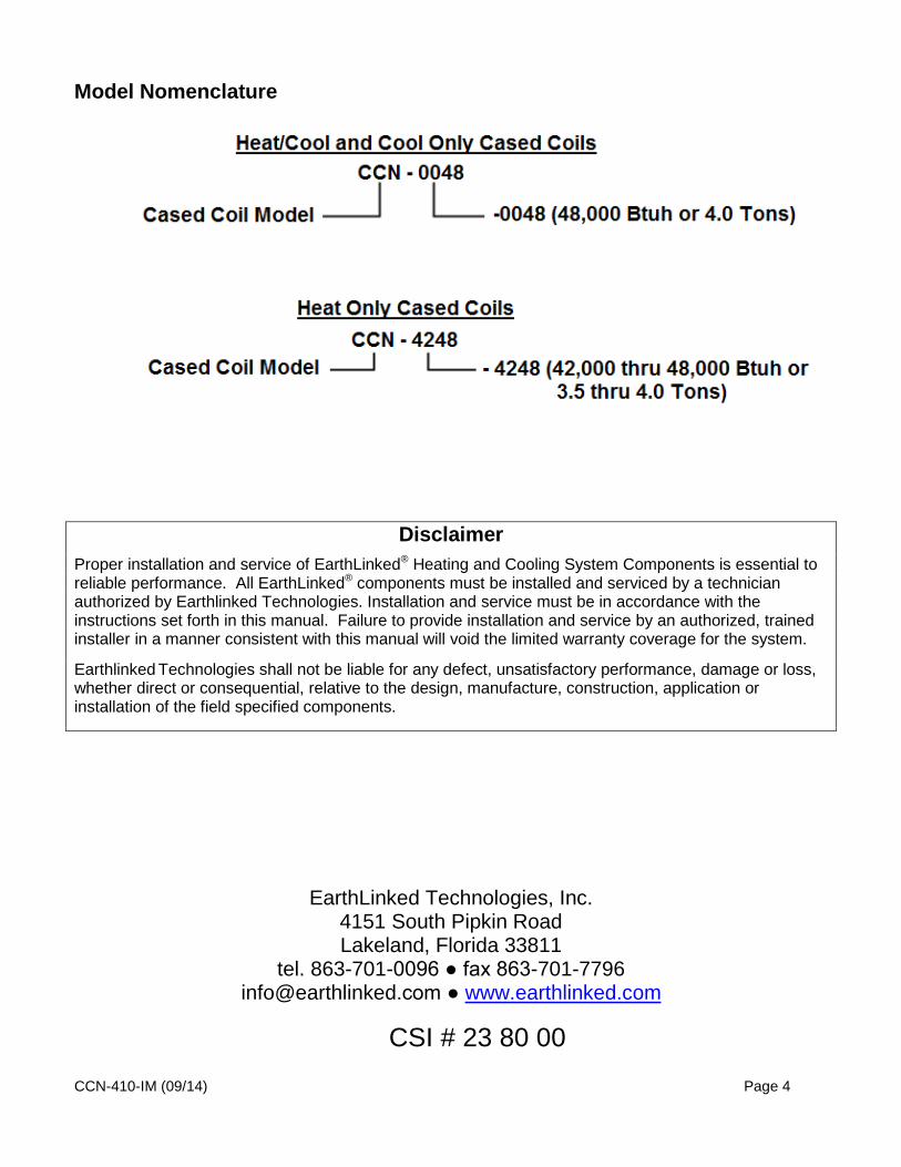
Model Nomenclature
Disclaimer Proper installation and service of EarthLinked® Heating and Cooling System Components is essential to reliable performance. All EarthLinked® components must be installed and serviced by a technician authorized by Earthlinked Technologies. Installation and service must be in accordance with the instructions set forth in this manual. Failure to provide installation and service by an authorized, trained installer in a manner consistent with this manual will void the limited warranty coverage for the system.
Earthlinked Technologies shall not be liable for any defect, unsatisfactory performance, damage or loss, whether direct or consequential, relative to the design, manufacture, construction, application or installation of the field specified components.
EarthLinked Technologies, Inc. 4151 South Pipkin Road Lakeland, Florida 33811
tel. 863-701-0096 ● fax 863-701-7796 [email protected] ● www.earthlinked.com
CSI # 23 80 00
CCN-410-IM (09/14) Page 5
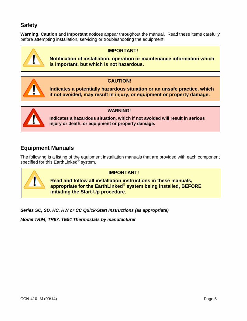
Safety Warning, Caution and Important notices appear throughout the manual. Read these items carefully before attempting installation, servicing or troubleshooting the equipment.
Equipment Manuals The following is a listing of the equipment installation manuals that are provided with each component specified for this EarthLinked® system.
Series SC, SD, HC, HW or CC Quick-Start Instructions (as appropriate)
Model TR94, TR97, TE54 Thermostats by manufacturer
CAUTION! Indicates a potentially hazardous situation or an unsafe practice, which if not avoided, may result in injury, or equipment or property damage.
IMPORTANT! Notification of installation, operation or maintenance information which is important, but which is not hazardous.
IMPORTANT! Read and follow all installation instructions in these manuals, appropriate for the EarthLinked® system being installed, BEFORE initiating the Start-Up procedure.
WARNING! Indicates a hazardous situation, which if not avoided will result in serious injury or death, or equipment or property damage.

CCN-410-IM (09/14) Page 6
Installation
Component Matching
CCN Series Cased Coils are ready for vertical installation as shipped. Field conversion to horizontal requires no additional components. The CCN Series Cased Coils are manufactured for both applications.
Heat/Cool and Cool Only (Model CCN-00XX): These cased coils are equipped with a distributor designed for providing optimum performance in the cooling mode and the heating mode. In addition, this cased coil includes a TXV Kit that is field installed external to the cased coil and is required to make the system operational in the cooling mode when matched with the appropriate model EarthLinked®
compressor unit as shown in Figure 1.
COMPRESSOR UNIT MODEL/CAPCITY
CASED COIL MODEL TXV-KIT MODEL**
-018 (1.5 Tons) CCN – 0018 TXV-018N -024 (2.0 Tons) CCN – 0024 TXV-024N -030 (2.5 Tons) CCN – 0030 TXV-030N -036 (3.0 Tons) CCN – 0036 TXV-036N -042 (3.5 Tons) CCN – 0042 TXV-042N -048 (4.0 Tons) CCN – 0048 TXV-048N -054 (4.5 Tons) CCN – 0054 TXV-054N -060 (5.0 Tons) CCN – 0060 TXV-060N
*TXV Kit is included with air handler for field installation
Figure 1. Heat/Cool and Cool Only Component Matchup
Heat Only (Model CCN-XXXX): These cased coils are to be matched with the appropriate model EarthLinked® Compressor unit model shown in Figure 2.
COMPRESSOR UNIT MODEL/CAPCITY
CASED COIL MODEL
-018 (1.5 Tons) CCN – 1824 -024 (2.0 Tons) CCN – 1824 -030 (2.5 Tons) CCN – 3036 -036 (3.0 Tons) CCN – 3036 -042 (3.5 Tons) CCN – 4248 -048 (4.0 Tons) CCN – 4248 -054 (4.5 Tons) CCN – 5460 -060 (5.0 Tons) CCN – 5460
Figure 2. Heat Only Component Matchup

CCN-410-IM (09/14) Page 7
Cased Coil Placement
Guidelines for the cased coil (or air handler) placement relative to the compressor unit and other EarthLinked® system components are shown in Figure 3.
Figure 3. General Layout of System Components
WARNING! WEAR ADEQUATE PROTECTIVE CLOTHING AND PRACTICE ALL APPLICABLE SAFETEY PRECAUTIONS WHILE INSTALLING THIS EQUIPMENT. FAILURE TO DO SO MAY RESULT IN EQUIPMENT AND/OR PROPERTY DAMAGE, PERSONAL INJURY OR DEATH.

CCN-410-IM (09/14) Page 8
Dimensions for the cased coils are illustrated and listed in Figure 4.
Compressor Unit Model
Heat/Cool, Cool Only
Model
Heat Only Model
Overall Width
W
Overall Height
H
Liq. Line Height/OD
HL/OD
Suc. Line Height/OD
HS/OD
Opening Width OW
-018 CCN – 0018 CCN-1824 14-1/4” 20-3/4” 17-1/2”,
3/8” 15-1/2”,
3/4” 12-7/8” -024 CCN – 0024
-030 CCN – 0030 CCN-3036 17-1/2” 20-3/4” 17-1/2”,
3/8” 15-1/2”,
3/4” 16-1/8” -036 CCN – 0036
-042 AVN – 0042 CCN-4248 21” 26-3/4” 23-1/2”,
3/8” 21-1/2”,
3/8” 19-5/8” -048 AVN – 0048
-054 AVN – 0054 CCN-5460 21” 30-1/4” 27”,
3/8” 25”, 7/8” 19-5/8”
-060 AVN – 0060
Figure 4. General Air Handler Physical Dimensions
Specific instructions for the mechanical installation of the cased coil are provided in Appendix A of this manual.

CCN-410-IM (09/14) Page 9
Refrigeration
Line Set Line set sizes for CCN Series Cased Coils connecting to the matching compressor units are listed in Figure 5. Line set liquid and vapor lines are to be insulated with Armaflex®, Insul-Lock® or equivalent tubing insulation at least ½” wall thickness. For interior living areas, thicker walled insulation will reduce sound level.
LINE SET ADAPTERS REQUIRED FOR THE AIR HANDLER, CASED COIL, HYDRONIC WATER MODULE AND DOMESTIC WATER MODULE ARE FIELD SUPPLIED. CHECK ALL APPROPRIATE COMPRESSOR UNIT STUB-OUT TUBING SIZES FOR REQUIRED FIELD SUPPLIED ADAPTERS! EARTHLOOP, AIR HANDLER, CASED COIL LINE SETS HWM/DWM LINE SETS COMPRESSOR
UNIT SIZE LINE SET O.D., INCHES HWM
MODEL LINE SET O.D., INCHES
LIQUID* VAPOR* LIQUID* VAPOR* 1.5 Tons (-018) 3/8 5/8 -018C/-1836 3/8 1/2 2.0 Tons (-024) 3/8 5/8 -024C/-1836 3/8 1/2 2.5 Tons (-030) 3/8 3/4 -030C/-1836 3/8 1/2 3.0 Tons (-036) 1/2 3/4 -036C/-1836 3/8 1/2 3.5 Tons (-042) 1/2 3/4 -042C/-4248 1/2 5/8 4.0 Tons (-048) 1/2 7/8 -048C/-4248 1/2 5/8 4.5 Tons (-054) 1/2 7/8 -054C/-5472 1/2 3/4 5.0 Tons (-060) 1/2 7/8 -060C/-5472 1/2 3/4
*Liquid and Vapor lines must BOTH be insulated with Armaflex® or equivalent with at least 1/2” wall thickness for the full length of the line set.
Figure 5. Line Set Sizes
Both liquid and vapor lines running between the compressor unit and the cased coil must be separated by an air space, as illustrated in Figure 6, to ensure system performance. The lines shall not be “bundled” by tying them together or by running both lines together, in contact with one another, within a single conduit, such as PVC pipe.

CCN-410-IM (09/14) Page 10
Figure 6. Cased Coiland Air Handler Line Set Separation
CCN-410-IM (09/14) Page 11
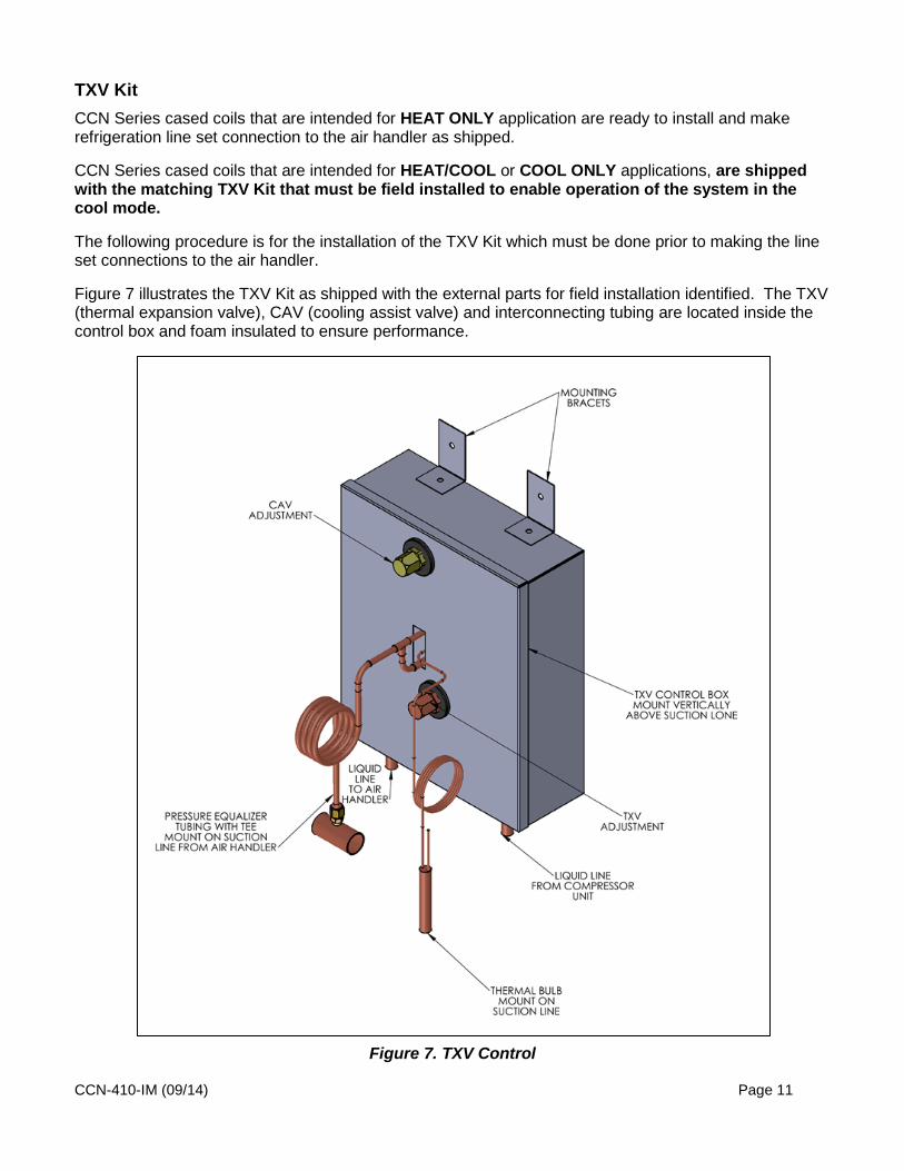
TXV Kit CCN Series cased coils that are intended for HEAT ONLY application are ready to install and make refrigeration line set connection to the air handler as shipped.
CCN Series cased coils that are intended for HEAT/COOL or COOL ONLY applications, are shipped with the matching TXV Kit that must be field installed to enable operation of the system in the cool mode.
The following procedure is for the installation of the TXV Kit which must be done prior to making the line set connections to the air handler.
Figure 7 illustrates the TXV Kit as shipped with the external parts for field installation identified. The TXV (thermal expansion valve), CAV (cooling assist valve) and interconnecting tubing are located inside the control box and foam insulated to ensure performance.
Figure 7. TXV Control

CCN-410-IM (09/14) Page 12
The TXV control box in Figure 8 is positioned external to the cased coil, located on a vertical mounting surface immediately adjacent to the cased coil. The TXV control box is to be mounted in the vertical position and above the cased coil tubing stub outs as shown in Figure 8, whether the cased coil is installed in the vertical or horizontal position.
Figure 8. TXV Control Installed near Cased Coil (Vertical Application)
Mount the TXV Kit on a solid flat surface with space at least 14-1/2 inches high by 10-1/2 inches wide upon which to locate the TXV box. Allow another 4 inches of clearance below the TXV Kit to install and braze liquid line fittings. Allow 12 inches clearance in front of the TXV box to access the superheat adjustment.
The steps for installing the TXV Kit are as follows:
Step 1: Relieve the nitrogen holding charge on the air handler using the valve on the liquid line stub out. Locate the TXV Control box within the 3-1/2 feet of the suction line stub out on the cased coil. Fasten the TXV control box in the vertical position, located above the suction line stub out.

CCN-410-IM (09/14) Page 13
Step 2: After removing the plug from the suction stub out and cutting the valve off the liquid line, position the Pressure Equalizer Tee on the suction tube at least 10 inches downstream from the 90° ell as shown in Figure 9. Remove the core from Schrader valve on the Tee.
Figure 9. Positioning the Pressure Equalizer Tee
Step 3: The Thermal Bulb must be positioned and clamped to the suction tube as shown in the example illustrated in Figure 10. The Thermal Bulb and suction tube must be horizontal regardless of the cased coil application (vertical or horizontal).
The Thermal Bulb must be positioned at the 3:00, 4:00, 8:00 or 9:00 positions on the suction tube, as illustrated in Figure 10.

CCN-410-IM (09/14) Page 14
Figure 10. Thermal Bulb Positioning
Step 4: Clamp the thermal bulb firmly against the clean suction tube extension and parallel to it, as shown in Figure 11.
Isolate the Thermal Bulb from with a cold wet cloth while Nitrogen brazing the joints on the suction line. After the suction line has cooled, apply the supplied cork tape insulation around the Thermal Bulb to completely isolate it from the surrounding air, as shown in Figure 12.

CCN-410-IM (09/14) Page 15
Figure 11. Clamping the Thermal Bulb
Figure 12. Insulating the Thermal Bulb

CCN-410-IM (09/14) Page 16
Step 5: Measure and cut copper tubing to connect the liquid line from the TXV control box to the liquid line stub out on the cased coil as shown in Figures 7 and 13. Run the other liquid line from the connection on the TXV control box to the compressor unit, also shown in Figure 13. Nitrogen braze the joints. Step 6: Replace the core in the Schrader valve and connect the pressure equalizer tube to the Schrader valve. Tighten the flare connection firmly. Wrap the liquid and vapor tubing including the liquid line tubing to the TXV control box, with Armaflex®, Insul-Tube® or equivalent insulation of at least ½” wall thickness, between the cased coil and compressor unit.
Figure 13. TXV Liquid Line Connections

CCN-410-IM (09/14) Page 17
Airflow CCN Cased Coils are designed to operate at 400 cfm/Ton, nominal capacity.
For system design purposes, Figure 14 provides the airflows for each CCN cased coil model and the associated coil pressure drops.
Cased Coil Model Airflow, cfm Coil Pressure Drop, in W.C.
CCN-0018 CCN-0024 CCN-1824
400 0.04* 600 0.06* 800 0.12
CCN-0030 CCN-0036 CCN-3036
800 0.15* 1000 0.22* 1200 0.30
CCN-0042 CCN-0048 CCN-4248
1200 0.19* 1400 0.24* 1600 0.30
CCN-0054 CCN-0060 CCN-5460
1600 0.15* 1800 0.23* 2000 0.30
*Projected pressure drop based on similar cased coils
Figure 14. Airflow Vs. Pressure Drop

CCN-410-IM (09/14) Page 18
Service Parts Service Parts for the CCN Series Cased Coils are illustrated in Figure 15 and listed in Figure 16.
Service parts for these cased coils can be purchased from HVAC distributors handling the following name brands of Nordyne Cased Coil Model Series C6. To find your nearest distributor, call 1-800-422-4328, option 2.
Frigidaire Nordyne
Gibson Nutone
Philco Tappan
Kelvinator Westinghouse
Maytag
Figure 15. CCN Cased Coil Parts Illustration

CCN-410-IM (09/14) Page 19
DESCRIPTION
CASED COIL MODELS
CCN-0018 CCN-0024 CCN-1824
CCN-0030 CCN-0036 CCN-3036
CCN-0042 CCN-0048 CCN-4248
CCN-0054 CCN-0060 CCN-5460
Replacement Coil Assembly 920562 920568 920572 920574 Drain Pan 669669 669670 669671 669671
TXV Assembly N/A N/A N/A N/A Distributor Assembly 664406 664407 664407 664408 Tie Bar, Upper 297221 297222 297223 297223 Tie Bar, Lower 297231 297232 297233 297233 Coil Capture Bracket, Front 295502 295502 295502 295502 Coil Capture Bracket, Rear 295512 295512 295512 295512 Door, Upper 297241 297242 297243 297243 Door, Lower 297151 297161 297171 297172 Wrapper 297251 297261 297271 297272 Plate, Coil Spacing 280621 2A1721 298011 297901 Horizontal Drain Pan Kit 920265 920265 920266 920267 Fitting, Liq Lineset, C6 664378 664378 664378 664378 Fitting, Liq Lineset Retain Nut 664387 664387 664387 664387 Bulkhead Nut, TXV 606287 606287 606287 606287 Bulkhead Washer, TXV 612068 612068 612068 612068 Bulkhead Extension, Dogleg 664494 N/A N/A N/A
Figure 16. CCN Cased Coil Parts Listing

CCN-410-IM (09/14) Page 20
Appendix A Cased Coil – Mechanical Installation Information*
Page
General Information ................................................................................................................... 21
Upflow Installations .................................................................................................................... 21
Horizontal Installations ............................................................................................................... 21
Downflow Installations ............................................................................................................... 22
Condensate Drain ...................................................................................................................... 22
*CCN Series Cased Coils are referred to as “C6” cased coils in this appendix.

CCN-410-IM (09/14) Page 21

CCN-410-IM (09/14) Page 22