
Heathkit RC-1 Geiger Counter Manual - dvq.com
24
ASSEMBLY AND OPERATION OF THE HEATHKIT RADIATION COUNTER MODEL RC-1 SPECIFICATIONS Time Constant: . ........................ 0.5, 1, 5 and 10 seconds Ranges: . .............................. 0-100, 600, 6000 and 60,000 counts per minute 0-.02, .1, 1 and 10 milliroentgens per hour Meter: . ................................. Calibrated 4 1/2" 200 MICRO ampere movement Probe:. ................................ Satin aluminum and chrome plated steel probe contains extra sensitive type 6306 Bismuth geiger counter tube. Speaker:. ............................... Loudspeaker driven by transistor gives pleasant tones on most sensitive range, no harsh clicks. Muted by panel control. Calibration: . ........................... Calibrate control on panel, radioactive sample furnished. Batteries: . ............................ 1 - 67 1/2 volt B battery (approximately 200 hours to 40 volt end point), intermittent operation. 2 - 11/2 volt A batteries (approximately 20 hours to 1 volt end point), intermittent operation. Tube Complement: . . . . . . . . . . . . . . . . . . . 1 - 1U4 Amplification, pulse shaping and 1 - 3V4 counting tubes. 2 - 1U5 1 - 5841 corona regulator tube 1 - 6306 bismuth counter tube 1 - 2N109 transistor (oscillator) Provision for use of external meter ( j a c k on panel). Prewired high voltage power supply assembly. Regulated 900 volt DC applied to 6306 tube in probe. Coiled cord between probe and instrument, no tangling. Cabinet: . ....................... Aluminum, 9 1/2" high x 6 1/2" wide x 5" deep Net Weight: . .................... 6 1/2 Ibs. Shipping Weight:. ................. 8 Ibs.
Transcript of Heathkit RC-1 Geiger Counter Manual - dvq.com

ASSEMBLY AND OPERATION OF THEHEATHKIT RADIATIONCOUNTER
MODEL RC-1SPECIFICATIONS
Time Constant:. . . . . . . . . . . . . . . . . . . . . . . . . 0.5, 1, 5 and 10 secondsRanges:. . . . . . . . . . . . . . . . . . . . . . . . . . . . . . . 0-100, 600, 6000 and 60,000 counts per minute
0-.02, .1, 1 and 10 milliroentgens per hourMeter:. . . . . . . . . . . . . . . . . . . . . . . . . . . . . . . . . . C a l i b r a t e d 4 1 / 2 " 2 0 0 M I C R O a m p e r e m o v e m e n tProbe:. . . . . . . . . . . . . . . . . . . . . . . . . . . . . . . . . S a t i n a l u m i n u m a n d c h r o m e p l a t e d s t e e l p r o b e
contains extra sensitive type 6306 Bismuth geigercounter tube.
Speaker:. . . . . . . . . . . . . . . . . . . . . . . . . . . . . . . . Loudspeaker driven by transistor gives pleasant tones on most sensitive range, no harsh clicks.
Muted by panel control.Calibration:. . . . . . . . . . . . . . . . . . . . . . . . . . . . Calibrate control on panel, radioactive sample
furnished. Batteries:. . . . . . . . . . . . . . . . . . . . . . . . . . . . . 1 - 6 7 1 / 2 v o l t B b a t t e r y ( a p p r o x i m a t e l y 2 0 0
hours to 40 volt end point), intermittent operation. 2 - 11/2 volt A batteries (approximately 20 hours to 1 volt end point), intermittent operation.
Tube Complement:. . . . . . . . . . . . . . . . . . . 1 - 1U4 Amplification, pulse shaping and 1 - 3V4 counting tubes. 2 - 1U5 1 - 5841 corona regulator tube 1 - 6306 bismuth counter tube 1 - 2N109 transistor (oscillator)
Provision for use of external meter (jack on panel).Prewired high voltage power supply assembly.Regulated 900 volt DC applied to 6306 tube in probe.Coiled cord between probe and instrument, no tangling.Cabinet:. . . . . . . . . . . . . . . . . . . . . . . . A l u m i n u m , 9 1 / 2 " h i g h x 6 1 / 2 " w i d e x 5 " d e e pNet Weight:. . . . . . . . . . . . . . . . . . . . . 6 1/2 Ibs.Shipping Weight:. . . . . . . . . . . . . . . . . . 8 I b s .


INSTRUMENT DESCRIPTIONThe Heathkit Radiation Counter model RC-1 is a highly developed instrument, designed expressly for the seriousprospector. A prewired power supply delivering the required high voltage, coupled with a four tube amplifying andpulse shaping circuit, gives extremely high sensitivity far in advance of most other counters now available,regardless of cost. A large 4 1/2" meter calibrated in counts per minute gives f u l l scale readings from 100 cpm to60,000 cpm. The meter is also calibrated in milliroentgens per hour (mR/hr) from .02 mR/hr to 10 mR/hr full scale.
An added feature is the use of a loudspeaker for aural monitoring, excited by a transistor oscillator, thusallowing a more pleasing (to the ear) tone than the usual harsh clicks. To further increase its flexibility, thecircuit has been so designed to operate accurately and sensitively with the Heathkit Geiger Counter Probemodel GC-1, which uses a bismuth counter tube. Using the model GC-1 Geiger Counter Probe with the modelRC-1 Radiation Counber comprises an instrument more sensitive but otherwise equal to many now selling for$250.00 or more. A calibrated, completely safe radiation source is provided with each model RC-1 for spotcalibration in the field.
THEORY OF OPERATIONNegative pulses generated in the probe are impressed across the input grid resistor through the .01 ufdblocking capacitor and are amplified and inverted by V1, appearing across the 68 K plate load resistor. V2further amplifies and reinverts the signal pulses and injects them into the grid of V3. The two stages ofamplification have been designed to have a sensitivity of approximately .1 volt and to limit at an input of .25volts. This insures a pulse of the proper amplitude for triggering V3, even though the input pulses may varyconsiderably in height.
V3 and V4 together constitute a mono-stable multivibrator, sometimes called a "one-shot," since it makes onecomplete cycle for each pulse (trigger). Operation is as follows: The two tubes have a common cathode resistorof 15K serving as one leg of the coupling impedance necessary for oscillation and also serving as a source ofcut-off bias for V4. The control grid of V3 is returned to a positive point on the voltage divider connectedbetween B+ and ground, causing it to conduct. This conduction causes current flow through the commoncathode resistor and the voltage drop across it is sufficient to cut V4 off, since the grid of V4 is returned toground. This enables the use of a tube with comparatively large emission capabilities as V4 without increasingthe B battery drain, since V4 is not allowed to draw current except during the short operating cycle following eachinput trigger. The RANGE switch connects various precision capacitors between the plate of V3 and the grid ofV4 and, in conjunction with the common cathode resistor, provides the necessary cross-coupling to enablemultivibrator operation. The capacitors switched between the two tubes determine the period of time themultivibrator will remain in its unstable state. This in turn determines the average current flowing through themeter. The meter is calibrated in both COUNTS PER MINUTE and MILLIROENTGENS PER HOUR. The useof precision capacitors to determine the range and therefore the current for full scale meter deflection enablesthe use of a single calibration control. Calibration made at one point will hold to within 10% at all points. Thecalibration control also enables the instrument to be calibrated even when the B battery is quite weak. Theoverall circuit including the power supply sub-assembly has been designed to operate correctly until the Bbattery voltage has dropped to 40 volts and/or the filament batteries have dropped to 1 volt or less. This hasbeen done to enable longest battery life commensurate with reliable operation and to preclude the necessity forcarrying an excessive number of spare batteries in the field.
An interesting departure from the usual method for aural monitoring has been incorporated inthis instrument. A transistor oscillator, using an output transformer as the oscillatory inductance, derives itsoperating voltage from the voltage drop across a by-passed portion of the plateload resistance for V4, voltage being present only during unstable state immediately following theinput trigger pulse. A small loudspeaker is connected directly across the output transformer andreproduces the audio tone generated by the transistor oscillator. This tone may be varied byadjustment of the 2K PITCH control to that most pleasing to the operator., Since it is an audiotone and not a click, it can be recognized in even the noisiest locations and is invaluable whenprospecting in a moving vehicle or aircraft.
Page 3

Two filament batteries (ordinary flashlight cells) and a 67 1/2 volt B battery (such as is used inmost portable radios) supply all operating voltages for the instrument. The power supply sub-assembly derives i ts operating voltage from the 67 1/2 volt B battery. Its output voltage issufficiently high (greater than 1200 volts) that it may be regulated at 900 volts for use with theGeiger Counter Probe.
The meter used is a 4 1/2" 200 microampere movement for greatest sensitivity combined withruggedness. When the instrument is turned OFF, the RANGE switch puts a short across the meterfor added protection. A TIME CONSTANT circuit has been incorporated to give added flexibilityto the counter, allowing a meter time constant of 1/2 second to 10 seconds. The 1/2 secondposition of the TIME CONSTANT switch is used when moving over the ground rapidly and the 10second position is used when checking ore samples for the greatest accuracy.
OPERATION OF THE CORONA REGULATOR TUBE(Courtesy of Victoreen Instrument Company)
The Corona Voltage Regulator tube exhibits many unique virtues when properly used to regulatethe output voltage of a high voltage, low current power supply. Like any other type of regulator, itcan be a tremendous source of annoyance when improperly used. Among its virtues are itssimplified circuits, low cost, good regulation, low power consumption, small spread betweenstarting and operating voltages, and its ability to regulate against variations both in load currentand input voltage. It is also mechanically rugged, supplies its own reference, has long operatinglife and a relatively wide range of operating temperatures.
Since the operation of a corona tube is not widelyunderstood, a simplified discussion of its behavioris appropriate.
In general, it may be stated that when two coax-ially positioned cylindrical electrodes areenclosed in a gas-filled envelope and a DCpotential is applied between them in such adirection that the central electrode is positivewith respect to the outer, the unit may beconsidered as a variable resistor which is verycurrent sensitive. The volt-ampere relations willexhibit three distinctly different regions, asillustrated in Figure 1.The exact values of voltage and current for any one of these regions are determined by electrodedimensions as well as gas nature and pressure, and other considerations. When theseparameters are selected to provide a useful corona region, the other two regions become limited.Similarly, if the tube is designed for the glow region operation, the characteristic curve maypass through the corona region so quickly as to be hard to identify.
Roughly speaking, these three areas of operation may be distinguished by the location of anyvisible light. The corona will appear around the anode, while the glow appears adjacent to thecathode. The arc is visible between the two.
Obviously corona tubes are useful for high voltage-low current application, glow tubes for mediumvoltage-medium currents, while the arc involves higher orders of current and lower voltage drops.
As a voltage regulator, the corona tube is connected across the load whose voltage is to beregulated, in series with the resistor, in the same manner as the more familiar glow tube regulatorwould be used.
Page 4

The supply voltage is then divided between the series resistor and the parallel combination ofregulator and load, and the regulator tube tends to hold the voltage across the load constant.For circuit analysis, the tube may be considered as a constant voltage source (whose value isthe nominal operating voltage of the regulator) in series with a resistance (computed from thepublished regulation curve). For example, the type 5841, regulating at 900 volts with a regulationof 1.5% between 5-50 ua may be considered as a 900 volt battery in series with a resistor.
From this equivalent circuit, other parameters may be established. In most cases, thevariations in load are predetermined by the application, and the variations in unregulated supplyare imposed by its nature, so the problem becomes one of evaluating the series resistornecessary to produce the required degree of regulation. It should be pointed out that while highvalues of series resistance tend to produce the best percent regulation, they also produce thesmaller values of regulator tube current and vice versa. The circuit used in the HeathkitRadiation Counter tends to keep the operation of the tube as near the center of the corona regionas possible, since transients in the supply or load might cause the momentary operation of thetube below the corona region (temporary extinction) or above the corona region (glow and arc).In either case, serious instability would result.
When the supply voltage has appreciable ripple and/or large transients, such as are unavoidablein the vibrator or fly-back type, considerable filtering is necessary between the supply and theregulator. The positive peaks of the waveform of the voltage at the resistor in series with theregulator must not be permitted to drive the corona into the glow or arc region nor must thenegative peaks be permitted to fall below the striking voltage of the regulator. Either conditionmay introduce very objectionable AC components into the load.
The corona regulator greatly aids the filter in attenuating AC components. The AC componentsahead of the series resistor are attenuated at the load by the voltage divider action of the resistorin series with the parallel combination of the load and the dynamic resistance of the corona. Sincethe ratio of the series resistor to the parallel combination is usually high, the degree of attenuationof ripple is also high.
Due to the relatively small spread between striking and operating voltage, its relatively lowdynamic resistance (300 K at 50 uamperes), its relatively short ionizing and deionizing time, etc.,the corona regulator makes a very poor relaxation oscillator when confined to the corona region.For this reason, small capacities may safely be placed across it to improve filtering. However,care must be exercised, less a transient should inadvertently cause the tube to momentarily passsufficient current to swing it to the glow or arc region, which would dump the entire charge of theshunt capacitor into the tube and permanently damage it, as well as temporarily impairing itsregulation.
Like the glow tube, there is a minimumcurrent required to sustain the corona in astable condition, but unlike the glow tube,the corona tube may satisfactorily operatein its unstable low current area if by-passed with a capacitor to relieve thetransients produced in this region.Adequate filtering ahead of the regulator isrequired for this type of operation and thedegree of regulation may be slightlyimpaired when operating below thepublished minimum current. See Figure 2.
TYPE 6306 THYRODE TUBEA thyrode counter tube is a gas diode designed to produce an electrical pulse when its sensitivevolume is penetrated by an ionizing particle.
Page 5

Read the notes on soldering below. Crimp all leads tightly to the terminal before soldering.Be sure that both the lead and terminal are free of wax, corrosion or other foreign matter. Useonly the best rosin core solder, preferably a type containing the new activated fluxes such asKester "Resin-Five, " Ersin "Multicore" or similar types.
Resistors and controls generally have a tolerance of ±10% unless otherwise specified in the partslist. Therefore, a 100 K control may test anywhere between 90 K and 110 K. (The letter K iscommonly used to designate a multiplier of 1000.) Tolerances on capacitors are generally evengreater. Limits of +100% and -50% are common for some types. The components furnished withyour Heathkit have been specified to enable you to obtain maximum performance, accuracy andlife from the completed instrument.
PROPER SOLDERING PROCEDUREOnly a small percentage of Heathkit purchasers find it necessary to return an instrument for fac-tory service. Of these, by far the largest proportion function improperly due to poor or impropersoldering.
Correct soldering technique is extremely important. Good solder joints are essential if theperformance engineered into the kit is to be fully realized. If you are a beginner with noexperience in soldering, a half-hour's practice with odd lengths of wire and a tube socket will bea worthwhile investment.
High quality solder of the proper grade is most important. There are several different brandsof solder on the market, each clearly marked "Rosin Core Radio Solder." Such solders consistof an alloy of tin and lead, usually in the proportion of 50:50. Minor variations exist in the mixturesuch as 40:60, 45:55, etc. with the first figure indicating the tin content. Radio solders are formedwith one or more tubular holes through the center. These holes are filled with a rosin compoundwhich acts as a flux or cleaning agent during the soldering operation.
NO SEPARATE FLUX OR PASTE OF ANY KIND SHOULD BE USED. We specifically cautionagainst the use of so-called "non-corrosive" pastes. Such compounds, although not corrosiveat room temperatures, will form residues when heated. The residue is deposited on surroundingsurfaces and attracts moisture. The resulting compound is not only corrosive but actually destroysthe insulation value of non-conductors. Dust and dirt will tend to accumulate on these "bridges"and eventually will create erratic or degraded performance of the instrument.
NOTE: ALL GUARANTEES ARE VOIDED AND WE WILL NOT REPAIR OR SERVICEINSTRUMENTS IN WHICH ACID CORE SOLDER OR PASTE FLUXES HAVE BEENUSED. WHEN IN DOUBT ABOUT SOLDER, IT IS RECOMMENDED THAT A NEWROLL PLAINLY MARKED "ROSIN CORE RADIO SOLDER" BE PURCHASED.
If terminals are bright and clean and wires free of wax, frayed insulation and other foreignsubstances, no difficulty will be experienced in soldering. Crimp or otherwise secure the wire (orwires) to the terminal, so a good joint is made without relying on solder for physical strength.To make a good solder joint, the clean tip of the soldering iron should be placed against the jointto be soldered so that the terminal is heated sufficiently to melt solder. The solder is thenplaced against both the terminal and the tip of the iron and will immediately flow out over thejoint. Refer to sketch on Page 8. Use only enough solder to cover wires at the junction; it isnot necessary to fill the entire hole in the terminal with solder. Excess solder may flow intotube socket contacts, ruining the socket, or it may creep into switch contacts and destroy theirspring action. Position the work so that gravity tends to keep the solder where you want it.
Page 7
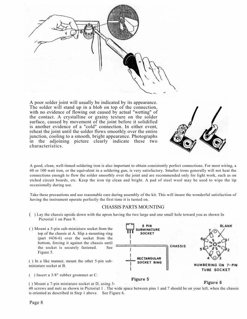
A poor solder joint will usually be indicated by its appearance.The solder will stand up in a blob on top of the connection,with no evidence of flowing out caused by actual "wetting" ofthe contact. A crystalline or grainy texture on the soldersurface, caused by movement of the joint before it solidifiedis another evidence of a "cold" connection. In either event,reheat the joint until the solder flows smoothly over the entirejunction, cooling to a smooth, bright appearance. Photographsin the adjoining picture clearly indicate these twocharacteristics.
A good, clean, well-tinned soldering iron is also important to obtain consistently perfect connections. For most wiring, a60 or 100 watt iron, or the equivalent in a soldering gun, is very satisfactory. Smaller irons generally will not heat theconnections enough to flow the solder smoothly over the joint and are recommended only for light work, such as onetched circuit boards, etc. Keep the iron tip clean and bright. A pad of steel wool may be used to wipe the tipoccasionally during use.
Take these precautions and use reasonable care during assembly of the kit. This will insure the wonderful satisfaction ofhaving the instrument operate perfectly the first time it is turned on.
CHASSIS PARTS MOUNTING( ) Lay the chassis upside down with the apron having the two large and one small hole toward you as shown In
Pictorial 1 on Paee 9.
( ) Mount a 5-pin sub-miniature socket from thetop of the chassis at A. Slip a mounting ring(part #436-6) over the socket from thebottom, forcing it against the chassis untilthe socket is securely fastened. SeeFigure 5.
( ) In a like manner, mount the other 5-pin sub-miniature socket at B.
( ) Insert a 3/8" rubber grommet at C.
( ) Mount a 7-pin miniature socket at D, using 3-48 screws and nuti as shown in Pictorial 1 . The wide space between pins 1 and 7 should be on your left, when the chassisis oriented as described in Step 1 above. See Figure 6.
Page 8
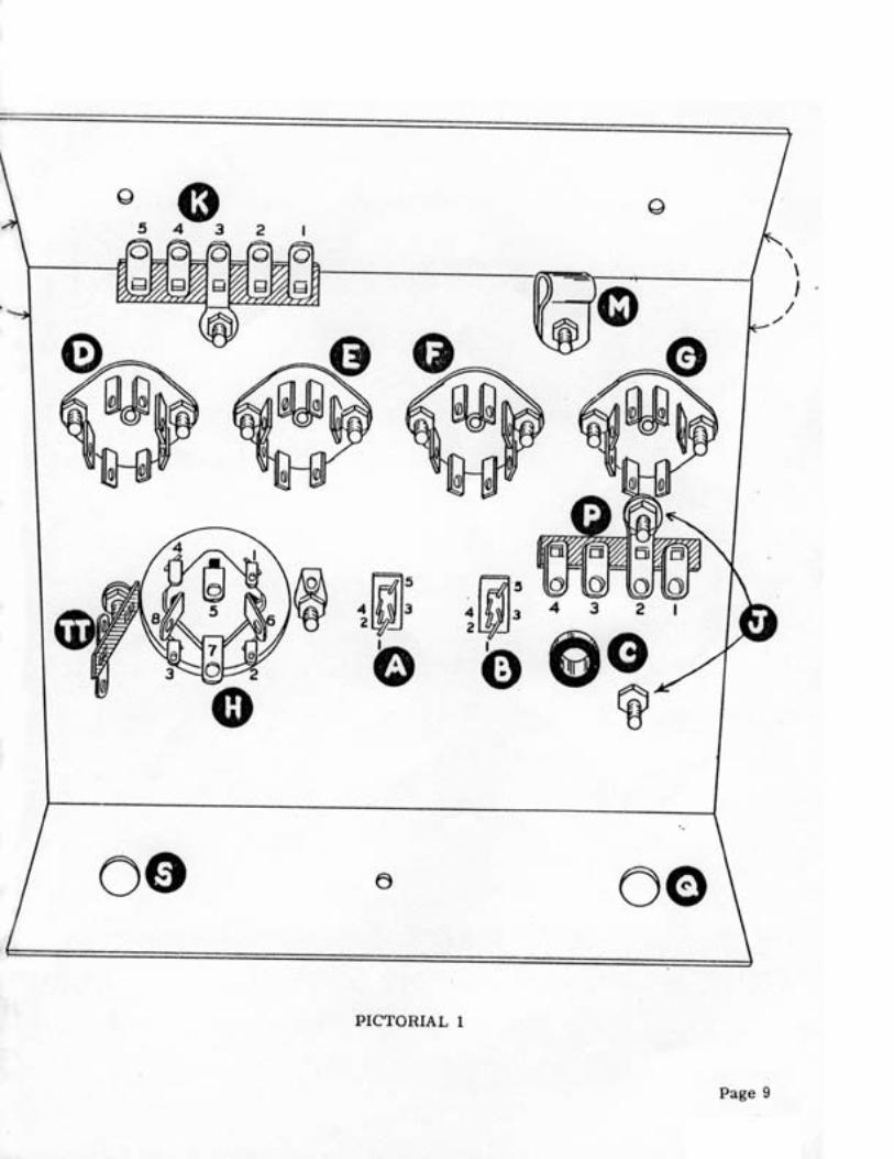
( ) In a like manner, mount the other three 7-pin sockets at E, F and G. Note the position of thewide space on these sockets. See Pictorial 1.
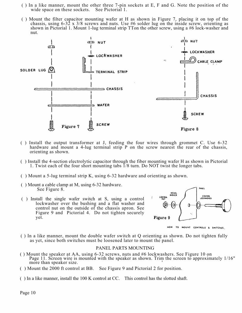
( ) Mount the filter capacitor mounting wafer at H as shown in Figure 7, placing it on top of thechassis, using 6-32 x 3/8 screws and nuts. Use #6 solder lug on the inside screw, orienting asshown in Pictorial 1. Mount 1-lug terminal strip TTon the other screw, using a #6 lock-washer andnut.
( ) Install the output transformer at J, feeding the four wires through grommet C. Use 6-32hardware and mount a 4-lug terminal strip P on the screw nearest the rear of the chassis,orienting as shown.
( ) Install the 4-section electrolytic capacitor through the fiber mounting wafer H as shown in Pictorial1. Twist each of the four short mounting tabs 1/8 turn. Do NOT twist the longer tabs.
( ) Mount a 5-lug terminal strip K, using 6-32 hardware and orienting as shown.
( ) Mount a cable clamp at M, using 6-32 hardware. See Figure 8.
( ) Install the single wafer switch at S, using a controllockwasher over the bushing and a flat washer andcontrol nut on the outside of the chassis apron. SeeFigure 9 and Pictorial 4. Do not tighten securelyyet.
( ) In a like manner, mount the double wafer switch at Q orienting as shown. Do not tighten fullyas yet, since both switches must be loosened later to mount the panel.
PANEL PARTS MOUNTING( ) Mount the speaker at AA, using 6-32 screws, nuts and #6 lockwashers. See Figure 10 on
Page 11. Screen wire is mounted with the speaker as shown. Trim the screen to approximately 1/16"more than speaker size. '
( ) Mount the 2000 ft control at BB. See Figure 9 and Pictorial 2 for position.
( ) In a like manner, install the 100 K control at CC. This control has the slotted shaft.
Page 10
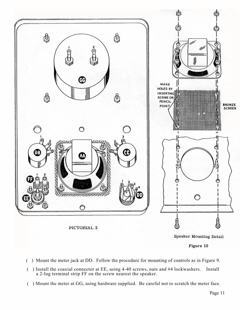
( ) Mount the meter jack at DD. Follow the procedure for mounting of controls as in Figure 9.
( ) Install the coaxial connector at EE, using 4-40 screws, nuts and #4 lockwashers. Installa 2-lug terminal strip FF on the screw nearest the speaker.
( ) Mount the meter at GG, using hardware supplied. Be careful not to scratch the meter face.
Page 11
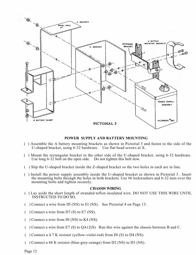
POWER SUPPLY AND BATTERY MOUNTING( ) Assemble the A battery mounting brackets as shown in Pictorial 3 and fasten to the side of the
U-shaped bracket, using 6-32 hardware. Use flat head screws at X.
( ) Mount the rectangular bracket to the other side of the U-shaped bracket, using 6-32 hardware.Use long 6-32 bolt on the open side. Do not tighten this bolt now.
( ) Slip the U-shaped bracket inside the Z-shaped bracket so the two holes in each are in line.
( ) Install the power supply assembly inside the U-shaped bracket as shown in Pictorial 3 . Insertthe mounting bolts through the holes in both brackets. Use #6 lockwashers and 6-32 nuts over themounting bolts and tighten securely.
CHASSIS WIRING( ) Lay aside the short length of stranded teflon insulated wire. DO NOT USE THIS WIRE UNTIL
INSTRUCTED TO DO SO.
( ) Connect a wire from Dl (NS) to El (NS). See Pictorial 4 on Page 13.
( ) Connect a wire from D7 (S) to E7 (NS).
( ) Connect a wire from Dl (NS) to K4 (NS).
( ) Connect a wire from E7 (S) to QA12(S). Run this wire against the chassis between B and C.
( ) Connect a 4.7 K resistor (yellow-violet-red) from Dl (S) to D4 (NS).
( ) Connect a 68 K resistor (blue-grey-orange) from D2 (NS) to D3 (NS).
Page 12

( ) Connect a 680 K resistor (blue-gray-yellow) from D6 (NS) to D4 (NS).
( ) Run a wire from D4 (S) to E4 (NS).
( ) Connect one lead of the .01 ufd 1.6 kv large ceramic capacitor to D6(S). Lay this capacitoragainst the chassis. Be certain neither lead is shorted to the chassis.
( ) Connect the other lead to TT (S).
( ) Connect a wire from E4 (NS) to SL1 (NS). Run this wire against the chassis.
( ) Cut the positive (+) lead of the 10 ufd 25 volt capacitor to 3/4". Connect to El (S). Placethis capacitor between H and E as shown. Connect the negative (-) lead to E4 (NS). Usesleeving on both leads.
( ) Run a wire from D3 (NS) to E3 (NS).
( ) Run a wire from D3 (S) around socket D and along the edge of the chassis to SI (NS).
( ) Cut both leads of an 1000 uuf disc capacitor to 1". Slip short lengths of sleeving over bothleads. Connect one lead to D2 (S). Connect the other lead to E6 (NS).
( ) Connect a 270 K resistor (red-violet-yellow) between E2 (NS) and E3 (NS).
( ) Connect a 680 K resistor (blue-gray-yellow) between E6 (S) and E4 (S).
( ) Connect a wire from E3 (NS) to F3 (NS).
( ) Connect a wire from Kl (NS) to Fl (NS).
( ) Connect a wire from Fl (S) to G5 (NS).
( ) Connect a 15 K resistor (brown-green-orange) from G5 (S) to F4 (NS).
( ) Run a wire from F4 (NS) to P2 (NS).
( ) Strip 1" of insulation from the end of a wire. Feed this bare wire end through Gl (NS) to
G7 (S).
( ) Connect the other end of this wire to F7 (S).
( ) Connect a wire from Gl (S) to QA8 (S).
( ) Cut both leads of an .01 ufd disc capacitor to 1" and slip short lengths of sleeving over eachlead. Connect one lead to E2 (S). Connect the other lead to F6 (NS).
( ) Connect a 2.2 megohm resistor (red-red-green) between F6 (NS) and F3 (NS).
( ) Connect a 1 megohm resistor (brown-black-green) between F6 (S) and F4 (S).
( ) Connect a 68 K resistor (blue-gray-orange) between F2 (NS) and F3 (NS).
( ) Connect a wire from F2 (S) to QB12 (S). Route this wire under the wiring between F and Gand between B and P.
( ) Connect a 1 megohm resistor (brown-black-green) between G6 (NS) and P2(NS) (use sleev-ing).
Page 14

( ) Connect a wire from G6 (S) to PI (NS).
( ) Run the red lead coming through grommet C along the inside edge of terminal strip P andconnect to G2 (NS).
( ) Connect a wire from G3 (NS) to QB6 (NS).
( ) Connect a 47 K resistor (yellow-violet-orange) between P4 (NS) and G3 (NS).
( ) Connect an 18 K resistor (brown-gray-orange) between G2 (NS) and P3 (NS).
( ) Connect a wire from G3 (S) to Hi (NS).
( ) Connect a .1 ufd capacitor between G2 (S) and HI (S) (use sleeving).
( ) Connect the green lead coming through grommet C to QB6 (S).
( ) Note the manner in which the pin connections to socket A and B appear. Carefully bend theoutside pins (Al, A5, Bl and B5) outward away from the socket. Use care to prevent breakingthese pins.
( ) Cut the blue wire extending through grommet C to length and connect to B5(S). Use extremecare when soldering connections to sockets A and B to prevent shorting the connectionstogether with excess solder.
( ) Connect a wire from QA7 (S) along the edge of the chassis and through the cable clamp M toK2 (NS).
( ) Connect a wire from QAll (S) routed as above to K5 (NS).
( ) Connect a wire from P2 (S) to QA1 (S).
( ) Connect a 100 uuf ±1% capacitor between QBl (S) and Pi (NS). Use sleeving on the leadgoing to P1.
( ) Connect a 2000 uuf ±1% capacitor between QB2 (S) and PI (NS).
( ) Connect a .02 ufd ±2% capacitor (matched pair, each .01 ufd) between QB3 (S) and PI (NS).
( ) Connect a .1 ufd ±2% capacitor (matched pair, each .05 ufd) between QB4 (S) and pi (S).Install as shown in Pictorial 4, making sure the leads do not short against the chassis.
( ) Run a wire from A5 (S) to SL1 (S). See Pictorial 4.
( ) Connect a wire from S2 (S) to H7 (S).
( ) Connect a wire from S3 (S) to H6 (S).
( ) Connect a wire from S4 (S) to H5 (S).
( ) Connect a wire from S5 (S) to H8 (S).
Page 15


PARTIAL ASSEMBLY AND WIRING
( ) Remove the nuts and flat washers from the two switches Q and S on the front chassis apron.
( ) Carefully mount the chassis to the panel as shown in Pictorial 5, inserting the switch shaftsthrough the matching holes in the panel. Install flat washers and nuts on both switches andtighten securely.
( ) Place the small gray knob on the shaft of the PITCH control CC and tighten.
( ) Rotate the shafts of switches Q and S fully counterclockwise, using pliers. Place one of thelarge skirted knobs on shaft Q with the index aligned with the OFF position and tighten.
( ) Similarly, place the other knob on shaft S with the index aligned with 10 SEC and tighten.
( ) For the following steps see Pictorials 4 and 5.
( ) Connect the black wire coming through grommet C to AA2 (NS).
( ) Connect a wire between Bl (S) and AA2 (S).
( ) Connect a wire between B2 (S) and BB2 (S).
( ) Connect a wire from BB1 (NS) to H3 (S).
( ) Connect a wire from BBl (S) to AAl (S).
( ) Connect a wire from BB3 (S) to P3 (S).
( ) Connect a wire from P4 (S) to CC2 (S).
( ) Connect a wire from CC1 (NS) to DD4 (S).
( ) Connect one end of an 8" wire to CC1 (S). Feed the other end of this wire up throughgrommet C and connect to GG2 (S). See Pictorial 2.
( ) Run a wire from QB5 (NS) through grommet C to GG1 (S).
( ) The B battery connector has yellow and black wires attached. Shorten the yellow lead to4 1/4" and the black lead to 2".
( ) Connect the yellow lead to F3 (S).
( ) Connect the black lead to QA2 (S).
( ) Connect a 5 1/4" wire to Kl (S). Leave the other end free.
( ) Connect a 3 1/4" wire to K2 (S). Leave the other end free.
( ) Connect a 4 1/4" wire to E3 (S). Leave the other end free.
( ) Connect a 4 1/2" wire to K3 (S). Leave the other end free.
( ) Connect a 6 1/2" wire to K4 (S). Leave the other end free.
( ) Connect a 3 1/2" wire to K5 (S). Leave the other end free.
( ) Connect a wire from QB5 (S) to DD1 (S).Page 17
( ) Connect a wire from DD2 (S) (outside terminal) to SI (S).
( ) Connect a 1 megohm (brown-black-green) resistor between FFl (NS) and EE (NS).
( ) Connect a .02 ufd 1.6 kv capacitor from FFl (NS) to FF2 (S).
( ) Identify the short length of teflon insulated wire. This is the short length of stranded wire. Theinsulation will have a soapy feel. DO NOT USE ORDINARY HOOKUP WIRE.
( ) Connect a 5" length of teflon wire between EE (S) and TT (S).
( ) Connect a 6" length of teflon wire between FFl (NS) and A3 (S).
( ) Connect a 7 3/4" length of teflon wire to FFl (S). Leave the other end free.
( ) Mount the handle on the front panel as shown in the photograph on Page 1. Insert a 10-24screw through the 7/32" hole between Q and S from the inside of the chassis. Do not tightenuntil the hole in the other end of the handle is aligned with the 7/32" hole below the speaker.Do not insert the other screw yet.
( ) Now check your wiring and remove any wire ends or other foreign matter before proceeding.
( ) Mount the power supply and battery assembly in place as shown in Pictorial 6 on Page 19. Use the other 10-24 screw and tighten securely.
( ) Connect the wire coming from E3 to ZZ INPUT (S).
( ) Connect the wire coming from K3 to ZZ GROUND (NS),
( ) Connect the lead coming from FFl to ZZ OUTPUT (NS).
( ) Connect a .02 ufd 1.6 kv capacitor between ZZ GROUND (S) and ZZ OUTPUT (S).
( ) Connect the wire coming from Kl to YY1 (S). See Pictorial 6.
( ) Connect the wire coming from K2 to YY2 (S).
( ) Connect the wire coming from K4 to YY3 (S).
( ) Connect the wire coming from K5 to YY4 (S).
( ) Insert the two 1.5 volt batteries in the battery clip YY. Observe polarity as shown inPictorial 6.
( ) Snap the battery connector to the B battery and insert battery in the battery clamp. Tightenthe clamping bolt. Do not overtighten as this will damage the battery.
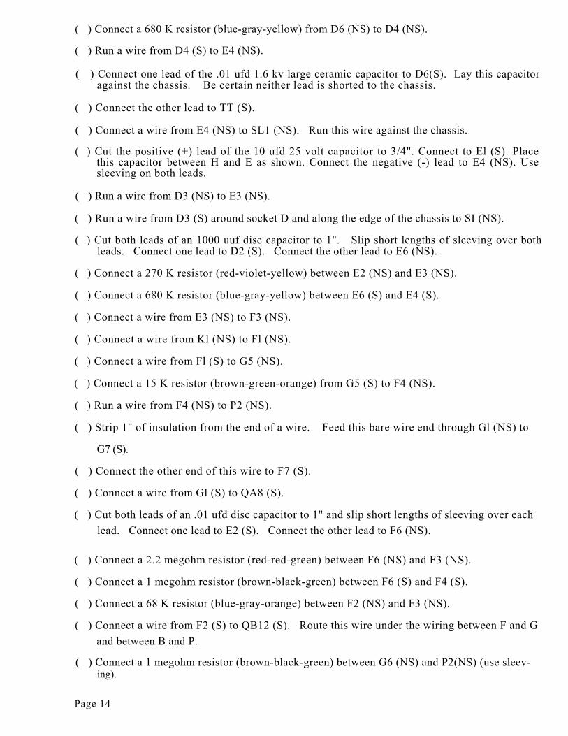
( ) Insert the 2N109 transistor in socket B, making certain the wide space is to the rear on the side closest to the tubes. Be sure the wire leads of the transistor mate with the proper pins of the socket. If the transistor is plugged in wrong, it may well be damaged. See Figure 11 A.
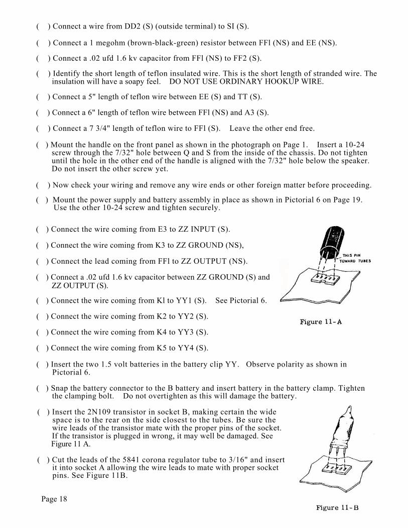
( ) Cut the leads of the 5841 corona regulator tube to 3/16" and insert it into socket A allowing the wire leads to mate with proper socket pins. See Figure 11B.
Page 18
( ) Plug the remaining miniature tubes in the proper sockets. Be sure the tubes are pluggedinto the proper socket, otherwise the instrument will not operate properly and tubes or othercomponents may be damaged.
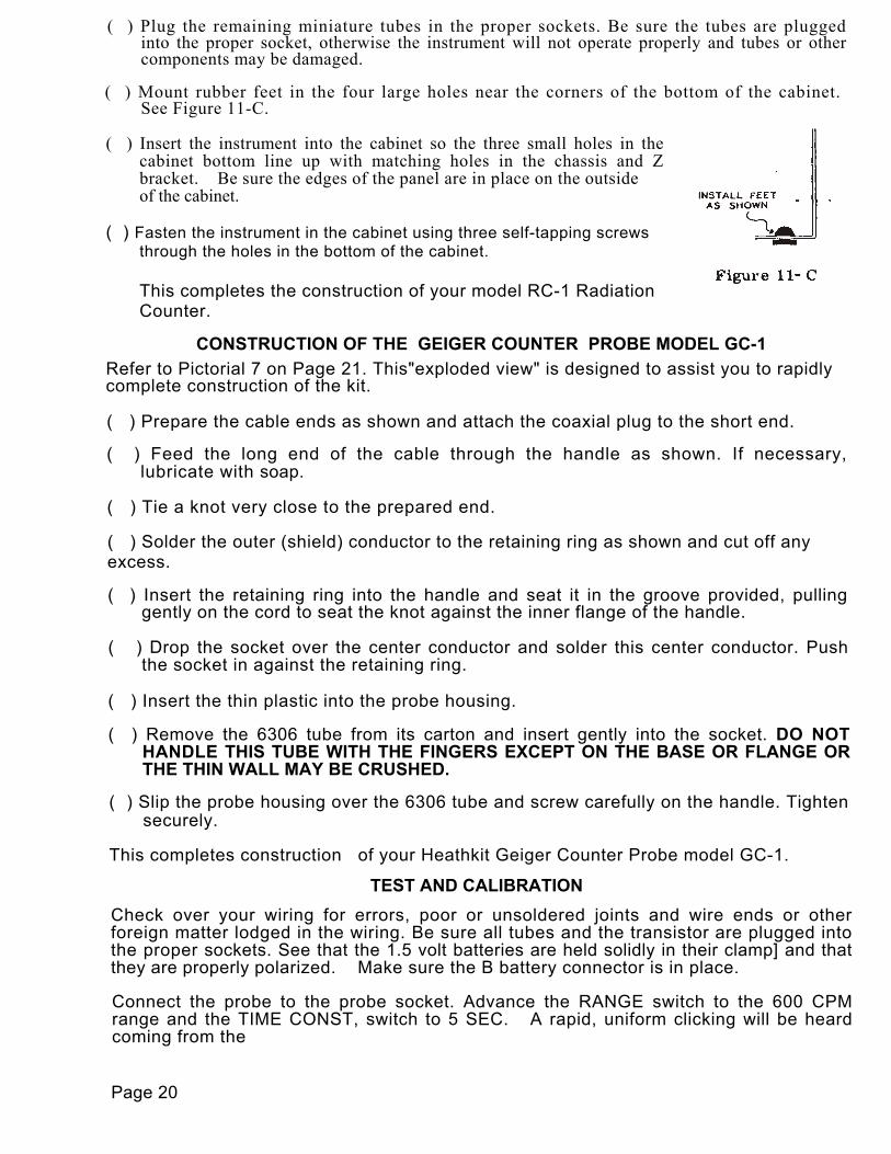
( ) Mount rubber feet in the four large holes near the corners of the bottom of the cabinet.See Figure 11-C.
( ) Insert the instrument into the cabinet so the three small holes in thecabinet bottom line up with matching holes in the chassis and Zbracket. Be sure the edges of the panel are in place on the outsideof the cabinet.
( ) Fasten the instrument in the cabinet using three self-tapping screwsthrough the holes in the bottom of the cabinet.
This completes the construction of your model RC-1 RadiationCounter.
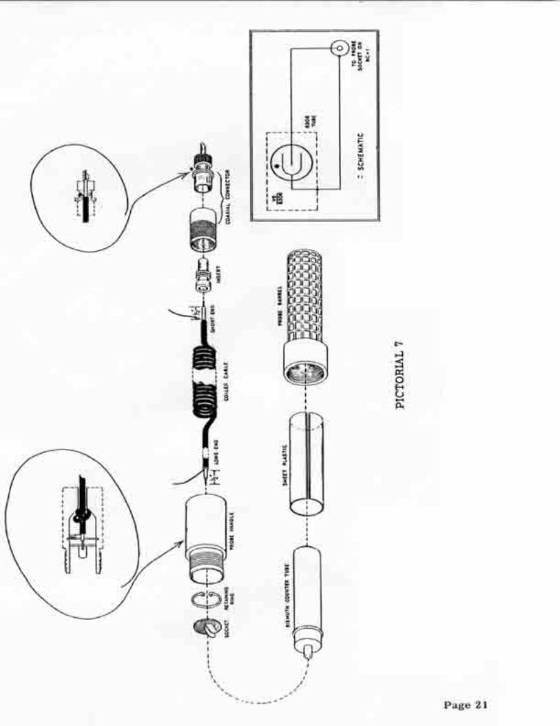
CONSTRUCTION OF THE GEIGER COUNTER PROBE MODEL GC-1Refer to Pictorial 7 on Page 21. This"exploded view" is designed to assist you to rapidlycomplete construction of the kit.
( ) Prepare the cable ends as shown and attach the coaxial plug to the short end.
( ) Feed the long end of the cable through the handle as shown. If necessary,lubricate with soap.
( ) Tie a knot very close to the prepared end.
( ) Solder the outer (shield) conductor to the retaining ring as shown and cut off anyexcess.
( ) Insert the retaining ring into the handle and seat it in the groove provided, pullinggently on the cord to seat the knot against the inner flange of the handle.
( ) Drop the socket over the center conductor and solder this center conductor. Pushthe socket in against the retaining ring.
( ) Insert the thin plastic into the probe housing.
( ) Remove the 6306 tube from its carton and insert gently into the socket. DO NOTHANDLE THIS TUBE WITH THE FINGERS EXCEPT ON THE BASE OR FLANGE ORTHE THIN WALL MAY BE CRUSHED.
( ) Slip the probe housing over the 6306 tube and screw carefully on the handle. Tightensecurely.
This completes construction of your Heathkit Geiger Counter Probe model GC-1.
TEST AND CALIBRATIONCheck over your wiring for errors, poor or unsoldered joints and wire ends or otherforeign matter lodged in the wiring. Be sure all tubes and the transistor are plugged intothe proper sockets. See that the 1.5 volt batteries are held solidly in their clamp] and thatthey are properly polarized. Make sure the B battery connector is in place.
Connect the probe to the probe socket. Advance the RANGE switch to the 600 CPMrange and the TIME CONST, switch to 5 SEC. A rapid, uniform clicking will be heardcoming from the
Page 20

power supply unit. This is normal and indicates the power supply is working. The meter needlewill be indicating above zero at this time; the exact reading is immaterial. If any sound is comingfrom the speaker, rotate the PITCH control knob fully counterclockwise. Place the radioactivecalibrating sample on a clean surface. Lay the probe against the calibrating sample as shown.
Place the RANGE switch in the X10 position and adjust the CALIBRATE control with ascrewdriver until the meter reading is 1 MR/hr. Screw the plastic cap nut over theCALIBRATE control shaft. Remove the sample to a point several feet from the probe. Advancethe RANGE switch to the 100 CPM position. Advance the TIME CONST, control to the 10 SEC.position. The reading on the meter is the normal background for your present location. Using theGC-1 probe, a normal background reading will most likely be 60-80 cpm. It is impossible to givethe specific figure for "normal" background count, since the background reading varies fromplace to place. The figures given above are only approximations, at best.
IN CASE OF DIFFICULTYRecheck your wiring and connections; better still, have a friend do it for you, since he mayreadily notice an error consistently overlooked. If the wiring is correct and all connections areproperly made and soldered, it is first suggested that the tubes be checked. Since battery tubesare used, this should be done on a tube tester. DO NOT USE AN OHMMETER TO TEST FORFILAMENT CONTINUITY ON A BATTERY TUBE, SINCE THE DELICATE FILAMENT MAYVERY LIKELY BE BURNED OUT IN THE PROCESS. If the four miniature tubes are good andthe power supply is clicking rapidly, check the voltages as tabulated in the chart below.
TUBETYPE Pin 1 Pin 2 Pin 3 Pin 4 Pin 5 Pin 6 Pin 7
VI1U5 +2.75 +41 +67.5 0 NC NS +4.2
V21U4 +2.75 +67.5 +67.5 0 NC NS +4.3
V31U5 +20 +26 +67.5 0 NC +20 +21
V43V4 +21 +67.5 +67.5 NC +21 NS +21
Conditions:RANGE: ................. In 6000 CPM (X10) positionTIME CONST.........10 SECPITCH:....................ClockwiseProbe: .................. .Not attached to instrumentMeter: .................. .DC VTVM 11 megohm input impedanceBatteries: ............ .Fresh batteries installed
Page 22

All voltages are DC and are measured with respect to the chassis.
NC - no connection. NS - not significant.All voltages should be within ±25% of those listed in the chart.
NOTE: DO NOT ATTEMPT TO MEASURE THE DC VOLTAGE AT PIN 3 OF SOCKET A NORTHE VOLTAGE AT THE OUTPUT OF THE POWER SUPPLY OR AT THE PROBECONNECTOR. THE CORONA REGULATOR TUBE AND POWER SUPPLY MAY BEDAMAGED BY SUCH MEASUREMENT AND NO SATISFACTORY VOLTAGE INDICATIONWILL BE INDICATED ON THE METER DUE TO THE EXTREMELY HIGH SOURCEIMPEDANCE OF THE POWER SUPPLY. HIGH (200 MILLION OHMS) IMPEDANCEVOLTAGES SUCH AS THESE MAY BE MEASURED ONLY WITH AN ELECTROMETERVOLTMETER FOUND ONLY IN A FEW CERTAIN LABORATORIES.
Depending on local lighting conditions, you may or may not see the glowing filaments in the fourminiature tubes. Under no circumstances should a glow be noted in the corona regulator tube,as this indicates a defective tube or the likelihood of trouble in the high voltage circuits.
A series of high pitched tones or a roaring sound, depending on the range used, emanating fromthe speaker indicates proper operation of the transistor, and of the entire unit when the probe isattached. With no probe attached and all tubes and the transistor in place, there should be nosound from the speaker after the first minute of operation. Such sounds in this case would indicateeither wiring errors or poor lead dress, which must be corrected. In the event continueddifficulties are encountered, please refer to that section of this manual entitled SERVICE.
OPERATIONAttach the probe to the instrument and rotate RANGE switch to the proper position. Place TIMECONST, switch in the 5 SEC. position and advance the PITCH control to about mid-range. Adeflection of the meter will be noted and "beep" tones or roaring sounds, depending on the rangein use, will be heard coming from the speaker. Assuming there is no radioactive material inthe immediate vicinity, meter reading will be the background count and is caused by cosmic raysand stray gamma radiation. It is an indication that your radiation counter is operating normally.
Advance the TIME CONST, switch to 10 SEC. and note that the reading on the meter is steadier.Reduce the TIME CONST, to 1 SEC. and note the increasing fluctuation of the meter. Reducethe TIME CONST, to .5 SEC. The meter should fluctuate wildly and may occasionally go offscale. The choice of time constant has been made available so that you may use a time constantappropriate to your speed in covering the area in which you are prospecting. The shorter timeconstants are advantageous when covering ground rapidly, as when in a vehicle or mounted on ahorse or burro. The long time constants enable a more accurate reading to be made whenchecking ore samples or when grid prospecting a suspected anomaly. When prospecting, a timeconstant sufficiently short to enable the instrument to indicate any change in the normalbackground count is normally used.
In any instrument of this type, a calibrated meter is primarily a convenience, since specificabsolute readings have no meaning until referred to a normal (for that area) background count.Therefore, it is the magnitude of difference between two readings and not the readings them-selves, which have meaning for the prospector. An increase of 10% or more over backgroundcount, while not necessarily indicating the presence of a marketable uranium deposit, issuspicious and the area should be investigated thoroughly before proceeding.
Uranium is found in a great variety of materials. Nearly 100 species may be listed as uraniumminerals and we may list more than 200 if we count all the minerals in which uranium occurscommonly but is not an essential constituent.
Page 23

Most uranium minerals are black or bright shades of green, yellow and orange. These are mostaccurately identified and their uranium content determined by laboratory methods, but two criteriaeither singly or together aid in identifying them in the field. First, along with thorium and somepotassium minerals, uranium minerals are radioactive and generally can be detected and measured bya Geiger or scintillation counter. Second, some uranium minerals, particularly the bright coloredones, fluoresce under an ultraviolet lamp.
The common uranium oxides are uraninite and its colloform variety, pitchblende. These oxides areblack or brown and have specific gravities of 5 to 9.
The common uranium phosphates are autunite (yellow) and tobernite (green). The presence of theseminerals suggest that primary uranium minerals may be found at depth. Two uraniferous vanadates,carnotite and tyuyamunite, are important constituents of uranium deposits on the Colorado plateau. Both are a bright mustard or canary yellow.
Of all the uranium minerals, only uraninite, pitchblende, davidite, brannerite, carnotite, tyuyamunite,autunite, torbernite, uranophane and schroeckingerite generally form minable deposits under presenteconomic conditions. The other uranium minerals, however, are commonly associated with uraniumores and are useful clues to the possible presence of uranium deposits. Certain plants, like juniper andsaltbrush, take up uranium from the soil if any appreciable amounts are present. Uranium content ofthe plant will be 2 or 3 parts per million and indicates the presence of uranium ore within 50 feet ofthe surface.In selecting an area for prospecting, two approaches may be distinguished. One, the observational or"uranium is where you find it" approach and two, the analytical or "uranium is where it ought to be"approach. It will be no surprise to economic geologists to learn that most of the producing uraniumdeposits in the world were found through the "uranium is where you find it" approach, as were some ofthe recent discoveries in this country. It will pay both prospectors and geologists to continue to lookfor uranium wherever and whenever they have opportunity, regardless of whether or not the specificarea is supposed to contain uranium deposits.
The numerous occurrences of pitchblende veins in the Western States have about the same relation tothe occurrence of larger, minable deposits as smoke does to fire. It is well known that for everylarge oil field, there are several smaller ones and the same relationship holds with respect tomineral deposits. Further exploration in the vicinity of known occurrences seems sure, therefore,to reveal some minable deposits and additional prospecting in granitic, and metamorphic terranesmay well turn up important new districts. The possibilities for discovering additional importantsandstone deposits seem particularly promising, both within the Colorado plateau and elsewhere inthe Western States. It seems well worthwhile to examine all lenticular permeable formations in thewestern area, whether they are known to contain ore or not. The oldest formation of this type in anygiven district, particularly the parts where permeable facies interfinger with inpermeable ones,seem especially promising.
It is beyond the scope of this manual to teach geology and the science of prospecting. However, sufficientmaterial to guide the beginner and assist the professional prospector has been included. Several veryexcellent sources of study material have been suggested in the BIBLIOGRAPHY. Your public librarymay have many of these books and many others equally good, which have not been listed due to lack ofsufficient space.
BIBLIOGRAPHY
U.S. Government Publications, Supt. of Documents, U.S. Govt. Printing Office, Washington 25,D.C.Prospecting for Uranium; A. E. C. , 1951, 55c. Valuable, but slightly outdated. Prospecting with aCounter; A. E. C., rev. 1954, 30c. A well written and valuable book. Selected Readings on AtomicEnergy; A. E.C. 1954, 15c. A listing of pertinent books and periodicals. Selected Papers on UraniumDeposits in the U. S. U. S. G. S., Cir. 220, free. Discussion of
primary and secondary deposits of uranium bearing ore deposits in different rock formations.Very good maps and bibliography.
Page 24

Books available from the publisher:
Uranium Official Yearbook; New Science Inst., 330 South Beverly Drive, Beverly Hills, Calif.1955, $2.00. An extremely valuable book, comprehensive in scope.
Nininger, Robt. D. ; Minerals for Atomic Energy; Van Nostrand, New York City, 1954, $7.50This book is indispensable to the serious prospector. It discusses uranium, thorium andberyllium thoroughly and is world wide in coverage.
Proctor, Hyatt, Bullock; Uranium - Where it is and How to Find It; Eagle Rock Publishers, Box1581, Salt Lake City, Utah. Written by experts for the beginning prospector with emphasison the Colorado Plateau.
Excellent maps may be obtained from the following sources:
U. S. Geological Survey, Federal Center, Denver, Colorado or Washington 25, D. C PetroleumInformation, Continental Oil Bldg. , Denver, Colorado. This firm has excellent uranium maps of theRocky Mountain area, having been engaged in mapping that area since 1928.
REPLACEMENTSMaterial supplied with Heathkits has been carefully selected to meet design requirements and ordinarilywill fulfill its function without difficulty. Occasionally improper instrument operation can be traced to afaulty tube or component. Should inspection reveal the necessity for replacement, write to the HeathCompany and supply all of the following information:
A. Thoroughly identify the part in question by using the part number and description found inthe manual parts list.
B. Identify the type and model number of kit in which it is used.C. Mention the order number and date of purchase.D. Describe the nature of defect or reason for. requesting replacement.
The Heath Company will promptly supply the necessary replacement. Please do not return the originalcomponent until specifically requested to do so. Do not dismantle the component in question as this willvoid the guarantee. If tubes are to be returned, pack them carefully to prevent breakage in shipment asbroken tubes are not eligible for replacement. This replacement policy does not cover the freereplacement of parts that may have been broken or damaged through carelessness on the part of the kitbuilder.
SERVICEIn event continued operational difficulties of the completed instrument are experienced, the facilities ofthe Heath Company Service Department are at your disposal. Your instrument may be returned forinspection and repair for a service charge of $5.00 plus the cost of any additional material that may berequired. THIS SERVICE POLICY APPLIES ONLY TO COMPLETED INSTRUMENTS CONSTRUCTEDIN ACCORDANCE WITH THE INSTRUCTIONS AS STATED IN THE MANUAL. Instruments that arenot entirely completed or instruments that are modified in design will not be accepted for repair.Instruments showing evidence of acid core solder or paste fluxes will be returned not repaired.
The Heath Company is willing to offer its full cooperation to assist you in obtaining the specifiedperformance level in your instrument. Factory repair service is available for a period of one year fromthe date of purchase or you may contact the Engineering Consultation Department by mail. Forinformation regarding possible modification of existing kits, it is suggested that you refer to any one ormore of the many publications that are available on all phases of electronics. They can be obtained at orthrough your local library, as well as at any electronic outlet store. Although the Heath Company sincerelywelcomes all comments and suggestions, it would be impossible to design, test, evaluate and assumeresponsibility for proposed circuit changes for specific purposes. Therefore, such modifications must bemade at the discretion of the kit builder according to information which will be much more readilyavailable from some local source.
Page 25

SHIPPING INSTRUCTIONSBefore returning a unit for service, be sure that all parts are securely mounted. Attach a tagto the instrument giving name, address and trouble experienced. Pack in a rugged container,preferably wood, using at least three inches of shredded newspaper or excelsior on all sides .DO NOT SHIP IN THE ORIGINAL KIT CARTON AS THIS CARTON IS NOT CONSIDEREDADEQUATE- FOR SAFE SHIPMENT OF THE COMPLETED INSTRUMENT. Ship by prepaidexpress if possible. Return shipment will be made by express collect. Note that a carrier can-not be held liable for damage in transit if packing, in HIS OPINION, is insufficient.
SPECIFICATIONSAll prices are subject to change without notice. The Heath Company reserves the right to dis-continue instruments and to change specifications at any time without,.incurring any obligationto incorporate new features in instrument previously sold.
WARRANTYThe Heath Company limits its warranty of parts supplied with any kit to a period of three (3)months from the date of purchase. Replacement will be made only when said part is returnedpostpaid, with prior permission and in the judgment of the Heath Company was defective at thetime of sale. This warranty does not extend to any Heathkits which have been subjected to mis-use, neglect, accident and improper installation or applications. Material supplied with a kitshall not be considered as defective, even though not in exact accordance with specifications, ifit substantially fulfills performance requirements. This warranty is not transferable and ap-plies only to the original purchaser. This warranty is in lieu of all other warranties and theHeath Company neither assumes nor authorizes any other person to assume for them any otherliability in connection with the sale of Heathkits.
The assembler is urged to follow the instructions exactly as provided. The Heath Company as-sumes no responsibility or liability for any damages or injuries sustained in the assembly ofthe device or in the operation of the completed instrument.
HEATH COMPANYBenton Harbor, Michigan
PART PARTS DESCRIPTION PART PARTS DESCRIPTIONNo. Per Kit No. Per KitResistors 23-65 1 .1 ufd ±2% matched pair
1-16 1 4.7 K 1/2 watt (.05 ufd each)1-21 1 15 K 1/2 watt 23-70 1 .02 ufd ±2% matched pair1-25 1 47 K 1/2 watt (.01 ufd each)1-30 1 270 K 1/2 watt 25-4 1 10 ufd-25 volt electrolytic1-34 2 680 K 1/2 watt 25-40 1 5-10-50-100 ufd 25 volt elec1-35 3 1 megohm 1/2 watt1-37 1 2.2 megohm 1/2 watt Controls-Switches-Transformer1-60 2 68 K 1/2 watt 10-5 1 2 K control PITCH1-69 1 18 K 1/2 watt 10-43 1 100 K control CALIBRATE
63-111 1 Wafer switch RANGECapacitors 63-112 1 Wafer switch TIME CONST.20-13 1 100 uud ±1% mica 51-24 1 Output transformer20-18 1 2000 uuf ±1% mica21-14 1 1000 uuf disc ceramic Meter-Batteries-Speaker21-16 1 .01 ufd disc ceramic 401-11 1 Speaker21-38 2 .02 ufd 1.6 kv disc ceramic 407-32 1 Meter21-42 1 .01 ufd 1.6 kv disc ceramic 418-4 1 67.5 volt battery23-28 1 .1 ufd 200 volt tubular 418-5 2 1.5 volt battery
Page 26

PART PARTS DESCRIPTION PART PARTS DESCRIPTIONNo. Per Kit No. Per Kit
Tubes-Transistors Hardware
411-56 1 1U4 tube 250-2 8 3-48 screw411-83 2 1 U5 tube 250-4 4 4-40 x 3/8 screw411-84 1 3V4 tube 250-8 3 #6 self tapping screw417-1 1 2N109 transistor 250-9 12 6-32 x 3/8 screw411-87 1 5841 tube 250-11 2 6-32 flat head screw411-86 1 6306 tube 250-19 2 10-24 screw
252-1 8 3-48 nutSockets-Connectors-Jacks-Terminal Strips-Knobs 252-2 4 4-40 nut431-1 1 1-lug terminal strip 252-3 19 6-32.,nut431-11 1 5-lug terminal strip 252-7 5 3/8-32 control nut431-12 1 4-lug terminal strip 252-20 1 Plastic cap nut431-14 1 2-lug terminal strip 253-10 5 Control flat washer-431-24 2 Battery terminal board 254-1 18 #6 iockwasher432-7 1 Battery connector 254-4 5 Control Iockwasher434-15 4 7-pin miniature socket 254-9 4 #4 Iockwasher434-61 2 5-pin subminiature socket 259-1 1 #6 solder lug435-6 2 Socket ring, subminiature 261-4 4 Rubber feet436-5 1 Coaxial connector 250-13 1 6-32 x 1" screw436-6 1 Meter jack462-19 2 Knob, skirted w/index Miscellaneous462-30 1 Knob, small 73-1 1 3/8" grommet
100-77 1 Power supply assembly #667Sheet Metal Parts 207-3 1 Cable clamp90-41 1 Cabinet 310-2 1 Bronze screen200-M95 1 Chassis 481-3 1 Capacitor mounting wafer203-84F114 1 Panel 595-118 1 Instruction manual204-M94 1 Battery bracket 419-1 1 Radioactive sample204-M95 1 Power supply bracket204-M98 1 Battery stiffener bracket Geiger Counter Probe Parts204-99 1 Battery spring 211-3 1 Probe handle207-10 1 Battery clamp 253-29 1 Retaining washer208-3 1 Battery spring clip 347-6 1 Cable211-1 1 Handle 434-62 1 Socket
438-9 1 Coaxial plugWire 438-12 1 Insert344-1 1 length Hookup wire 476-9 1 Probe barrel344-5 1 length Teflon wire 446-M6 1 Sheet plastic346-1 1 length Sleeving


