HEATED HUMIDIFIER 6060 - · PDF fileThe heated humidifier 6060 is a piece of medical equipment...
28
Manual Code: 204040024 1 REV A Service Manual HEATED HUMIDIFIER 6060 Series 50.6060.100 Manual Code: 204040024 Revision: A (JAN/2001)
-
Upload
truongcong -
Category
Documents
-
view
220 -
download
1
Transcript of HEATED HUMIDIFIER 6060 - · PDF fileThe heated humidifier 6060 is a piece of medical equipment...

Manual Code: 204040024 1 REV A
Service Manual
HEATED HUMIDIFIER 6060 Series 50.6060.100
Manual Code: 204040024 Revision: A (JAN/2001)

Manual Code: 204040024 2 REV A
DEFINITIONS Warning
Warns the user as to the possibility of injury, death or other serious adverse reaction associated with the use or misuse of the equipment.
Attention
Warns the user about possible problems with the equipment, associated with its use or misuse, such as equipment malfunction or failure, damage to the equipment or damage to third party property.
Notes:
Underlines important information

Manual Code: 204040024 3 REV A
THE COMPANY K. TAKAOKA is a company that for more than 40 years has been dedicated to the hospital equipment industry, always in close cooperation with physicians. Working mainly in the areas of Anesthesia Machines, Pulmonary Ventilators, Monitoring and Oxygenotherapy, K. TAKAOKA is proud of its leading position in the market and presents an extensive range of products. With one of its priorities towards the solid investment into the research and development of new ideas and solutions, K. TAKAOKA has distinguished itself because of its continuous introduction of new technology and industrial innovations in its range of products, which puts it on a par with its principal national and international competitors. Using sophisticated equipment, K. TAKAOKA designs and manufactures most of the components used in its machines, which explains the strict quality control they undergo. The company is also concerned in supplying top quality assistance to all customers by means of its Sales and Technical Assistance departments. With representatives all over the country and being also present in the international market, K. TAKAOKA has justly deserved over the years the confidence of its customers in the high-quality standards and great efficiency of its products and services.

Manual Code: 204040024 4 REV A
TABLE OF CONTENTS 1 IMPORTANT NOTES......................................................................... 5 2 GENERAL DESCRIPTION ................................................................ 7 3 OPERATING PRINCIPLE .................................................................. 8 4 COMPONENT IDENTIFICATION ...................................................... 9 4.1 FRONT VIEW COMPONENTS............................................................................. 9 4.2 RIGHT VIEW COMPONENTS.............................................................................. 9 4.3 LEFT VIEW COMPONENTS .............................................................................. 10 4.4 REAR VIEW COMPONENTS............................................................................. 10 4.5 UPPER VIEW COMPONENTS ......................................................................... 10 4.6 INTERNAL COMPONENTS ............................................................................... 10 5 ELECTRIC/ELECTRONIC DESCRIPTION...................................... 13 5.1 SOURCE BOARD............................................................................................... 14 5.2 THERMOMETER BOARD.................................................................................. 15 5.3 PLACA CONTROLE DE TEMPERATURA......................................................... 16 5.4 ELTRICAL SCHEMES........................................................................................ 17 5.4.1 ELECTRICAL SCHEME OF THE THERMOMETER BOARD ............................ 17 5.4.2 ELECTRICAL SCHEME OF THE TEMPERATURE CONTROL BOARD ........... 18 5.4.3 CONNECTION SCHEMES................................................................................. 19 6 ELETRONIC ADJUSTMENT PROCEDURES................................. 21 7 POWER SUPPLY............................................................................. 22 8 REVISION PROGRAM..................................................................... 23 9 REPRESENTING.................................................…..........................24 10 TECHNICAL ASSISTANCE....................…......................................26

Manual Code: 204040024 5 REV A
1 IMPORTANT INFORMATION The heated humidifier 6060 is a piece of medical equipment developed to combine state-of-the-art technology with extreme ease of use. It should only be operated by qualified and trained professionals. All services for preventive or corrective maintenance should be performed by TAKAOKA's qualified professionals. Carefully review all warnings and recommendations in this manual. Before switching on Read the Operation Manual for the Heated Humidifier 6060.
Check that the liquid level does not exceed the maximum level as indicated in the chamber.
Check that the chamber lock is in the "closed" position.
Check the presence of the sealing ring in the chamber cap and that the chamber cap is tightly closed.
Prevent the external and lower metallic parts of the chamber from being in contact with liquids.
When supplying When supplying the chamber, be careful not to overfill it with liquid.
Do not fill the humidifying chamber with heated water above 37ºC.
Power supply Only connect the power cable to a tap which is properly grounded and approved for hospital use and to a power supply which complies with the ABNT NBR 13534 regulation - "Instalações elétricas em estabelecimentos assistenciais de saúde - Requisitos de segurança". The female tap should be a 3-pin Nema 5-15P female tap.

Manual Code: 204040024 6 REV A
General Always keep the contact base of the humidifier's body and the metallic surface of the chamber as clean as possible for a seamless contact between the humidifier's body and the chamber, thus allowing a perfect heat interchange.
The humidifier chamber should never run out of water.
Service (preventive and corrective maintenance) Any internal service in the Heated Humidifier 6060 must be exclusively performed by a trained technician authorized by TAKAOKA. This Service Manual does not exempt the proper training of the technician.
Use only TAKAOKA's original replacement parts. The use of non-original parts could risk the patient's safety.
The technical features of TAKAOKA's products are subject to changes without prior notice due to their constant technological development.
K. TAKAOKA IND. E COM. LTDA. Av. Bosque da Saúde, 519 São Paulo - SP - CEP:04142-091 Voice:(55 11)5586-1000 Fax:(55 11)5589-7313 E-mail: [email protected] Web site: http://www.takaoka.com.br

Manual Code: 204040024 7 REV A
2 GENERAL DESCRIPTION The Heated Humidifier was designed to heat and humidify gases supplied to the patient by an Intensive Therapy Ventilator, an Anesthesia Machine, or other positive pressure respiratory system. The Heated Humidifier is composed of the two parts described below: Heating Base The heating base has the heating and temperature control systems. It also has a mechanism for fixing the humidifying chamber. Humidifying Chamber Water reservoir where the humidifying process is performed. The humidifying chamber has standardized conical connections for the inlet and outlet of gas flow.

Manual Code: 204040024 8 REV A
3 OPERATING PRINCIPLE The Heated Humidifier operates under the principle of gas flow saturation by heated water steam, that is, it warms and saturates with water steam the inspiratory flow which passes through its chamber. Then the gases flow through a path between the chamber outlet and the patient by means of two corrugated tubes with drains. The air entering the Heated Humidifier is circulated inside a chamber filled with sterile water. This chamber is placed over a base containing a heating board. The board temperature is controlled by an electronic system which automatically and intermittently turns on and off an electric resistance, thus keeping the heating board temperature always constant. It has an electronic temperature control, a digital thermometer, pilot and electric resistance operation lights, on/off key, and transparent chamber with capacity for 400ml of sterile water. The gas temperature is measured near the patient's mouth by means of an electronic thermometer.

Manual Code: 204040024 9 REV A
4 COMPONENT IDENTIFICATION This chapter identifies the parts and components of the heated humidifier and its respective list of materials. Use these figures to find the Humidifier's internal components as well as a reference to perform the assembly and maintenance procedures. 4.1 Front View Components Figure 4.1: Components of the Heated Humidifier 6060
Code Description Quantity Unit 203010295 Button 1 Part 316030014 Grub screw with inter. hex 3/16” 1 Part 203010424 Pin 1 Part 203010471 Knob 1 Part 316030003 Grub screw with inter. hex NR 8/32Fx1/4” 2 Part 422010004 Linear potentiometer without key 100R 1 Part 310020015 Phillips flat head screw with gap D 8 Part 202020034 Humidifier's case 1 Part 202010970 Full polysulfone chamber 1 Part 203030564 Polysulfone chamber cap 1 Part 203040100 Humidifier chamber plug 1 Part 117050017 Poly. lexan 0.13espx914mmx58mts (exp) 1 Part 416020003 5mm green led 2 Part 203030009 Bushing - ext.dia.8xint.dia.4.5x6esp 2 Part
4.2 Right View Components Figure 4.1: Components of the Heated Humidifier 6060
Code Description Quantity Unit
406010031 On/off key ITB 24261G0603 (Emicol) 1 Part 421010002 Fuse-holder ref. 11005 or PFP 010606 1 Part 429090023 Supply cable 1 Part 434050001 Press cable ref. S-692 1 Part 429090024 Sensor cable 1 Part 203020449 Right side 1 Part

Manual Code: 204040024 10 REV A
4.3 Left View Components Figure 4.1: Components of the Heated Humidifier 6060
Code Description Quantity Unit
203020450 Left side 1 Part 4.4 Rear View Components Figure 4.1: Components of the Heated Humidifier 6060
Code Description Quantity Unit
203030556 Protector 2 Part 308020009 Phillips head screw with gap 4.2x9.5 2 Part 203100053 Engraved plate 1 Part 202020035 Base 1 Part 314020017 Phillips head screw with gap 4 Part 203030022 PVC feet 4 Part
4.5 Upper View Components Figure 4.1: Components of the Heated Humidifier 6060
Code Description Quantity Unit
203020178 Lock 2 Part 203010431 Heating board 1 Part 303010029 O’ring ref.2235-N 3000-7B 1 Part 203010434 Sensor 1 Part

Manual Code: 204040024 11 REV A
4.6 Internal Components Figure 4.1: Components of the Heated Humidifier 6060
Code Description Quantity Unit
203010425 Lever axis 1 Part 203010426 Protector mat 5840 1 Part 203060127 Retainer ring ref.503040-03 1 Part 203010429 Axis - diameter 3/16” 1 Part 322010102 Spring -
ext.dia.8xint.dia.7.2x20.5len.x0.9mmthick. 2 Part
203010081 Threaded pin 1/8”x40Fx15.2mm 8 Part 320010028 Threaded hex nut ¼”x40F. 12 Part 203020091 Washer - ext.dia.3/8”xint.dia.4.1x1mmthick. 4 Part 203030233 Insulating 4 Part 203010432 Insulating 4 Part 320010004 Threaded hex nut 1/8”x40F.key ¼”x3thick. 4 Part 314020009 Crosshead screw m3x0.58x5mm 8 Part 432010002 Thermostat 95degrees 1 Part 202010500 Temperature sensor 1 Part 203010433 Cap 1 Part 320010007 Threaded hex nut 1/2”x12F. 4 Part 317010045 Round head screw dia.3/32x48Fx5/8” 2 Part 203060126 Missagra ME-007 2 Part 203020454 Mica paper board 63x32x0.36mm 2 Part 203020453 Mica paper board 63x30x0.36mm 1 Part 445010032 Thermometer board 1 Part 445010062 Temperature control board 1 Part 433010001 Power supply cable 1 Part

Manual Code: 204040024 12 REV A
Figure 4.1: Components of the Heated Humidifier 6060

Manual Code: 204040024 13 REV A
5 ELECTRIC/ELECTRONIC DESCRIPTION The humidifier's electronics consists of three main boards. The voltage source board is bi-volt and externally manufactured, supplying a continuous voltage of 6.5V for the display board. The heating board is independent from the other two. The temperature sensor board is intended to indicate the temperature of gases supplied to the patient. The figure below shows the humidifier's block diagram. Figure 4.1 – Heated humidifier's block diagram
90 – 240v AC NETWORK
Source Board
6,5 VDC Thermometer Board
Temperature Sensor
Temperature Control Board
90 – 240v AC NETWORK Heating
Resistance
Base Temperature
Sensor
Temperature Adjustment
Potentiometer

Manual Code: 204040024 14 REV A
5.1 Source Board The source board converts the network voltage to 6.5v DC and only supplies the thermometer board.
This board may differ according to the humidifier, but it has the same function with the same inlet and outlet.
Inlet 90-240v AC
Outlet 6.5v DC

Manual Code: 204040024 15 REV A
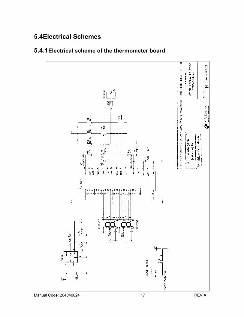
5.2 Thermometer Board The thermometer board is intended to indicate by means of a 2-digit LCD the temperature measured by the temperature sensor connected to the Y-shaped part. This thermometer has a 1oC resolution.
SupplyTemperature sensor
TP 1
TP 2

Manual Code: 204040024 16 REV A
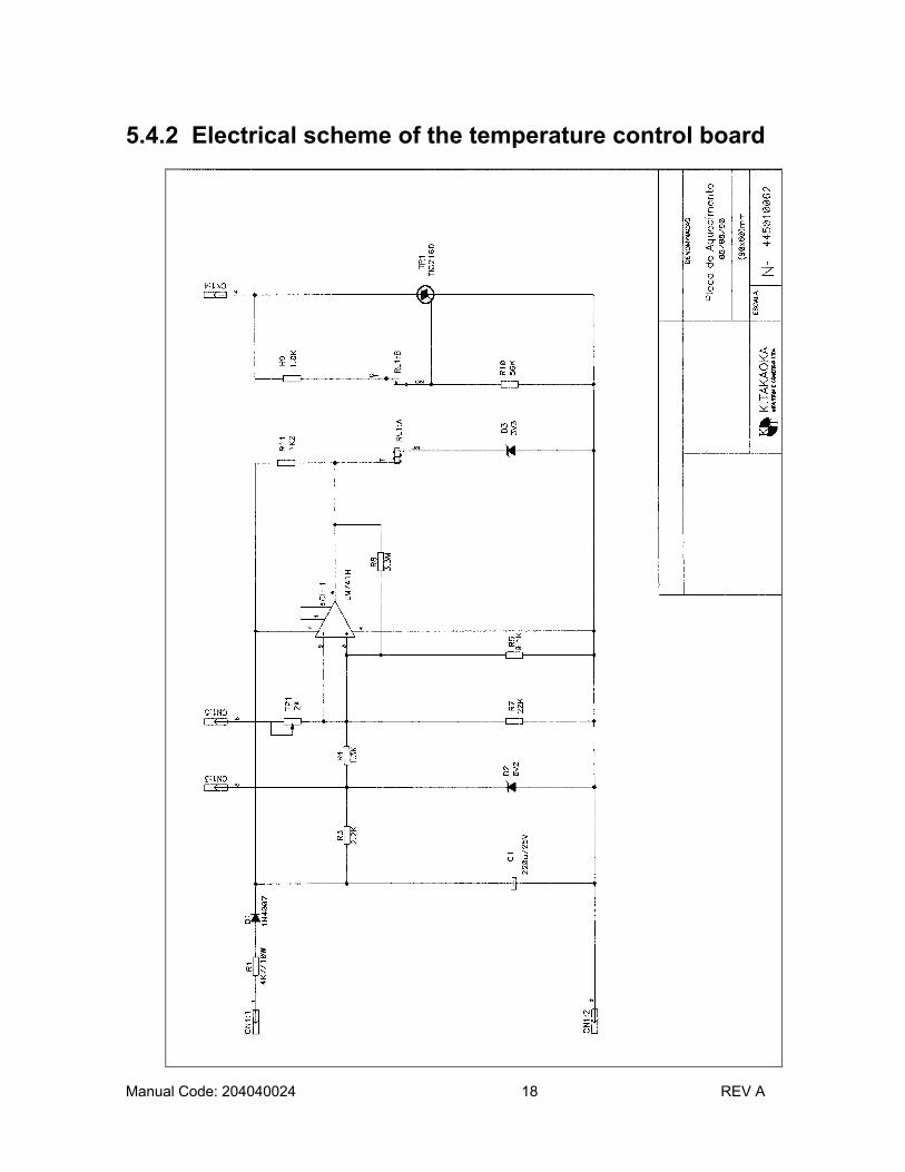
5.3 Temperature Control Board This board is intended to control the temperature of the aluminum base which will be in contact with the chamber. This base has a thermostat which will disrupt the current supplying the resistance if the temperature in the base reaches 90oC to prevent overheating of the humidifier's chamber. When temperature reaches the temperature adjusted by means of the potentiometer in the front part of the humidifier, the board will turn off the supply for the heating resistance. Once temperature falls some degrees below the temperature adjusted, the supply for the resistance will be resumed until it reaches once more the temperature adjusted and the cycle starts over.
Supply and Signals
TM1
Manual Code: 204040024 17 REV A
5.4 Electrical Schemes 5.4.1 Electrical scheme of the thermometer board
Manual Code: 204040024 18 REV A
5.4.2 Electrical scheme of the temperature control board

Manual Code: 204040024 19 REV A
5.4.3 Connection schemes

Manual Code: 204040024 20 REV A

Manual Code: 204040024 21 REV A
6 ELECTRONIC ADJUSTMENT PROCEDURE Material Required: 1 – Glass thermometer with scale up to 100oC. 1 – Small screwdriver. 1 – Recipient with ice. 1 – Thermometer for measuring room temperature. Calibration of the Temperature Control Module: 1 – Switch on the humidifier with the temperature control potentiometer in the maximum position. 2 – Place a reference thermometer to monitor the water temperature of the its reservoir. 3 – Wait for the water temperature to reach 50oC and then adjust TM1 (item 5.3) to turn off heating (the HEATER ON LED is dimmed in the panel). 4 – If heating is deactivated before the water reaches 50oC, adjust TM1 to reactivate it (the HEATER ON LED is on). 5 – Check that the humidifier keeps an ON-OFF routine during heating to keep water temperature at 50oC +/- 3oC. Calibration of the Thermometer Module: 1 – Place the temperature sensor within a recipient with ice in fusion. 2 – Once the reading is stable, adjust TP1 (item 5.2) so that “00” is indicated in the display. 3 – Remove the temperature sensor from the ice and leave it exposed to the room temperature. 4 – Once the reading is stable, check that the temperature matches the one from the standard thermometer (room temperature). Tolerance must be of +/-1oC. If necessary, adjust TP2 (item 5.2) to the display temperature and repeat items 1 to 4 until the process is stable.

Manual Code: 204040024 22 REV A
7 POWER SUPPLY Supply the heated humidifier with a 100 or 220v AC distribution network by means of the power cable provided with the equipment.
Figure. Three-pin electric Nema 5-15P tap.
1
3
2
LIGAÇÃO
PINO 110V 220V
1 NEUTRO FASE
2 FASE FASE
3 TERRA TERRA
CONEXION POINT 110 V 220 V
1 NEUTER PHASE 2 PHASE PHASE 3 GROUND GROUND
Manual Code: 204040024 23 REV A
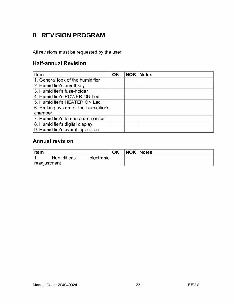
8 REVISION PROGRAM All revisions must be requested by the user. Half-annual Revision Item OK NOK Notes 1. General look of the humidifier 2. Humidifier's on/off key 3. Humidifier's fuse-holder 4. Humidifier's POWER ON Led 5. Humidifier's HEATER ON Led 6. Braking system of the humidifier's chamber
7. Humidifier's temperature sensor 8. Humidifier's digital display 9. Humidifier's overall operation
Annual revision Item OK NOK Notes 1. Humidifier's electronic readjustment

Manual Code: 204040024 24 REV A

Manual Code: 204040024 25 REV A

Manual Code: 204040024 26 REV A
TECHNICAL ASSISTANCE
K. TAKAOKA Indústria e Comércio Ltda. advises that only its Technical Assistance Centers are authorized to provide technical assistance for any equipment supplied by the company. Service provided by third parties implies the running of serious risks since the origin of the parts used is unknown and the labor does not conform to the strict quality standards laid down by K. TAKAOKA. We cannot guarantee the correct functioning of the equipment we manufactured when it has been serviced by unauthorized personnel. Any request for technical assistance and/or preventive maintenance, either by contract or not, shall be directed to K. TAKAOKA or one of its exclusively authorized representatives.

Manual Code: 204040024 27 REV A

Manual Code: 204040024 28 REV A
Information for Technical Assistance This card shall be filled in and returned with the equipament. Name Hospital Address Fone Number Block Zip Code
City State Failure Description : __________________________________________________________________________________________________________________________________________________________________________________________________________________
Fábrica: Av. Bosque da Saúde, 515 - CEP 04142-091 - Tel: (011) 5586-1000 - Fax: (011) 5589-7313 Vendas e Show-Room: Rua Bertioga, 385 - CEP 04141-100 - Tel: (011) 5586-1100 - São Paulo / SP
E-mail: [email protected] - Home Page: www.takaoka.com.br