Heatcraft Fundamentals Manual - icemeister.net
36
Refrigeration Fundamentals 2175 West Park Place Blvd., Stone Mountain, GA 30087 770-465-5600 www.heatcraftrpd.com
Transcript of Heatcraft Fundamentals Manual - icemeister.net

Refrigeration Fundamentals
2175 West Park Place Blvd., Stone Mountain, GA 30087 � 770-465-5600 � www.heatcraftrpd.com

Table of Contents
BASIC Principles Heat – energy form Measuring Heat Heat Flow Physical States Latent vs. Sensible Refrigeration process Saturation, Superheated, Subcooling Pressure/Temperature Refrigeration Cycle Compressor Flow Control Evaporator Condenser Accessories & Options Glossary
. . . . . . . . . . . . . . . . . . . . . . . . . . . . . . . . Pages 1-16. . . . . . . . . . . . . . . . . . . . . . . . . . . . . Page 1
. . . . . . . . . . . . . . . . . . . . . . . . . . . . . . . . Page 2. . . . . . . . . . . . . . . . . . . . . . . . . . . . . . . . . . Pages 2-3
. . . . . . . . . . . . . . . . . . . . . . . . . . . . . . Pages 3-4 . . . . . . . . . . . . . . . . . . . . . . . . . . . Pages 4-5
. . . . . . . . . . . . . . . . . . . . . . . . Pages 6-7 . . . . . . . . . . . . . . . Page 8
. . . . . . . . . . . . . . . . . . . . . . . . Page 9-11
. . . . . . . . . . . . . . . . . . . . . . . . . . . . . Pages 12-24 . . . . . . . . . . . . . . . . . . . . . . . . . . . . . . Pages 12-14 . . . . . . . . . . . . . . . . . . . . . . . . . . . . . . Pages 15-17
. . . . . . . . . . . . . . . . . . . . . . . . . . . . . . . Pages 18-20 . . . . . . . . . . . . . . . . . . . . . . . . . . . . . . . Pages 20-22
. . . . . . . . . . . . . . . . . . . . . . Pages 23-27 . . . . . . . . . . . . . . . . . . . . . . . . . . . . . . . . . Pages 28-33
Typical Commercial Refrigeration System
Evaporator
Compressor
SuctionFilter
Receiver
Liquid LineSolenoid Valve
Filter-Drier
Expansion Valve
Head PressureControl Valve
Condenser
Liquid LineSight Glass
Evaporator
Compressor
SuctionFilter
Receiver
Liquid LineSolenoid Valve
Filter-Drier
Expansion Valve
Head PressureControl Valve
Condenser
Liquid LineSight Glass
Page ii

INTRODUCTION
The information in this manual is meant for entry-level personnel to the commercial refrigeration industry to improve their understanding of the fundamentals of basic refrigeration principles. There are no specific technical prerequisites required prior to beginning this course material. The course is structured with the more basic and simple content presented first. It is important that the student have a good understanding of the presented material before continuing to more complex content, which may require a thorough grasp of previously covered material. This “building block” technique should allow students to quickly scan the material for understanding, begin more intense use of the material where understanding is known to be lacking, or refer to earlier content to improve understanding of more familiar topics. Further assistance is available by contacting Heatcraft Training Department in Stone Mountain or your local Heatcraft sales representative. Course objectives are to broaden useful knowledge of commercial refrigeration principles to improve efficiency on the job, allow for more flexibility in job duties, and increase the value of the student to their company and themselves. This manual should provide exposure to new resources and reinforce doctrines or beliefs, which the student may have already adopted. Simple terms and language will be used throughout the manual to assure that the student clearly comprehends the material. As the student progresses through the manual, more complex definitions and principles will be presented in the simplest terms possible. Our aim is to transfer information to the user in a manner easily understood. “When promulgating your esoteric cogitations or articulating your superficial sentimentalities and amicable philosophical and psychological observations, beware of platitudinous ponderosity. Let your verbal evaporations and lucidity, intelligibility and veracious vivacity without rodomontade or thespian bombast. Sedulously avoid all polysyllabic profundity, pompous propensity and sophomoric vacuity.” --- translation: Don’t use big words or confusing terms!
Page iii

BASIC Principles
Most of us have some ideas concerning the purpose of refrigeration and what refrigeration does. The illustration above is a consumer’s understanding of refrigeration. Your customers may not need to go beyond this simple understanding of refrigeration. However, they may expect you to have a much greater ‘in-depth’ understanding of refrigeration to help them solve their cooling needs. To be able to provide your customers with cooling solutions, you will need to have a firm grasp of the fundamental principles of basic refrigeration. This manual will help guide you through your quest to improve your knowledge of commercial refrigeration. What is refrigeration? The basic purpose of refrigeration is to remove heat from an area where it is not wanted. Your customers may need refrigeration to cool something that is a source of revenue for them. Normally this something is a perishable product or a process to prepare a product to be sold. They are only concerned with removing the heat from their sellable product and will rely on you to satisfy this cooling need.
Ice Cream Goes Here
Beer Goes Here
In practice, the refrigeration process must transfer heat from one body to another body. Usually, the heat is simply dumped into the outdoor air or down the drain where it is not objectionable. Heat reclaim, heat recovery or energy conservation occurs when the heat is sent to an area where it is needed or desired. Since refrigeration deals completely with the transfer of heat, to better understand how the refrigeration process works, it is necessary to first understand the nature of HEAT. Then we can control the transfer and removal of heat to reduce and maintain the temperature of a space or material below its natural surrounding temperature. What is heat? Heat is a form of energy like electricity. It comes to us from the sun and is present in every body on the earth. Like all other energy forms, the laws of physics govern it. Thermodynamics is the field of science that studies and deals with the mechanical action of heat. Simply stated, heat is work, and work is heat. From the first law of thermodynamics we learn that heat cannot be created or destroyed. Heat can be converted from one energy form to another and is never content to remain stationary or static. It is known as the energy in transfer and never stands still and is always on the move. All things above absolute zero (-459°F or -273°C) contain heat. Absolute zero is the temperature at which all atoms are at their slowest oscillation and is the coldest any material can be. Scientists have not been able to create this condition in laboratories or identify where it exists in the universe.
Page 1

BASIC Principles How is heat measured? As a form of energy, heat is intangible and cannot to be measured directly. It can be measured only by measuring the effect it has on a material, such as a change in temperature, state, size, color, etc. This measurement is sometimes referred to as work, heat content or quantity of heat. The total heat content of an object is measured in BTUs or calories based on these definitions: • BTU (British Thermal Unit) is the
amount of heat required to change 1 pound of water by 1°F at 1 atmosphere.
Lighting a kitchen match is equivalent to releasing 1 BTU of energy.
• Calorie is the amount of heat required to change 1 gram of water 1°C at 1 atmosphere.
The heat content of an object does not determine its temperature. Temperature is a property of matter that indicates the concentration or intensity of heat in a material. Higher intensities of heat have the atoms oscillating quickly, and the material is considered hot or warm. Lower intensities of heat have atoms oscillating slower with the material considered cold or cool. Cold is simply the absence of heat. Removing heat from a material makes it cooler or colder. An instrument used to measure temperature is a thermometer, which has a scale to indicate intensity.
212°F 100°C 373°K
32°F 0°C 273°K
AbsoluteZero -459°F -273°C 0°K
0°R
671°R
492°R
WaterBoils
WaterFreezes
212°F 100°C 373°K
32°F 0°C 273°K
AbsoluteZero -459°F -273°C 0°K
0°R
671°R
492°R
WaterBoils
WaterFreezes
Temperature scales are based on effects of heat on water with references to boiling and freezing points of water. One of two basic scales is normally used. The Fahrenheit temperature scale has water boiling at 212° and freezing at 32° with absolute zero at –459°. The Celsius temperature scale has water boiling at 100° and freezing at 0° with absolute zero at –273°. Scientists and engineers use the Kelvin and Rankin scales with 0° reference point at absolute zero. Kelvin scales uses Celsius increments, and Rankin uses Fahrenheit increments. How heat flows The second law of thermodynamics states that heat always moves from the warmer body to the colder object. Heat cannot move from the colder to the warmer object. There must be a temperature difference for heat to flow from one material to another. Like water, it will always seek its own level.
Page 2

BASIC Principles
There are three ways heat flows, passes, moves or transfers between bodies: • Conduction – heat passes by direct
contact between the bodies, from molecule to molecule.
• Convection – heat flows through available medias (such as fluids or gases), by riding piggyback on the moving molecule between the bodies.
• Radiation – heat moves on waves of energy carried by photons of light in the infrared and visible portions of the electromagnetic spectrum and does not rely on molecules.
Factors of heat flow The speed or rate of heat transfer between bodies is influenced by several factors. Temperature Difference (TD) – One of the most prominent of these factors is TD or temperature difference. If the TD between objects is great, heat will move quickly from the warmer object to the cooler one, and if the TD is small, heat will flow slowly. Without a temperature difference, no heat transfers. Example: Turn system thermostat down to cool off people or products faster. Surface Area – The amount of surface affects rate of transfer…more surface exposure allows from faster heat flow. Example: A drink cools quicker with crushed or shaved ice than larger ice cubes. Consider a 100-pound ball of meat vs. (400) ¼ pound patties…which one cools down faster in the same room conditions?
Type of Material – The material separating the bodies through which the heat must pass can either promote or retard the speed of heat movement. Conductors are a type of material, which will let heat pass through them easily and quickly. Insulators, however, will hinder or decrease the flow of heat through them. Example: Aluminum fins are used on cooling coils as conductor instead of plastic fins…insulation in walls to keep heat out of coolers and freezers. Exercise: Place one of your hands on a table or desk near you. It should feel cool to your touch. This is because the surface temperature of your hand is warmer than the table or desk. Keep it there for a minute. The heat from your hand should be flowing into the table or desk raising its temperature and lowering your hand’s temperature. Now place your hands together. The one that was on the table or desk should feel cool to your other hand. Heat transfer has taken place through conduction. How heat affects change of state Most substances can exist in a solid, liquid or gaseous (vapor) physical state. They can also change from one state to another through heating or cooling. The physical state change of a material from liquid to vapor is called evaporation (or boiling.) The material changes from a liquid to a vapor as it absorbs heat beyond its boiling point, but the temperature stays constant. A great amount of heat is needed to release the molecular bonds or attraction of the liquid.
Page 3
BASIC Principles Changing state in the opposite direction from vapor to liquid is called condensation. As the vapor rejects heat below its boiling point, it changes into a liquid. The heat it loses to change state is just as great. Fusion occurs when a material rejects heat below its melting/fusion point, as it changes from liquid to solid state. The reciprocal change from solid to liquid form, or melting, is a result of absorbing heat beyond its melting point. The same amount of heat is rejected or absorbed to cause the change of physical state for fusion or melting. Sublimation occurs when a material changes from solid to vapor without turning to a liquid. An example of this is dry ice. Pressure/Temperature Relationships The boiling and melting points at which materials change physical state are influenced by the pressures exerted on them. For any one substance, its boiling point temperature is the same and remains constant, under a fixed pressure. Example: Water boils at 212°F at sea level or 1 atmosphere where the weight of the atmosphere above the earth is exerting 14.7 pounds per square inch. But at higher altitudes, there are fewer atmospheres and less pressure being exerted, and water will boil at a lower temperature because lower surface tension will allow the molecules to escape at a lower velocity. As pressure increases, the saturation point increases changing the boiling and condensing temperatures, and visa versa, as the pressure decreases so does the saturation point…less vapor/surface tension on molecules to maintain bond/attraction.
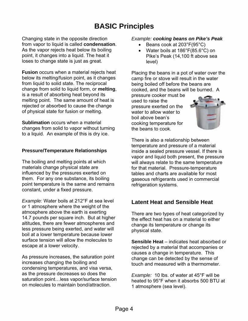
Example: cooking beans on Pike’s Peak • Beans cook at 203°F(95°C) • Water boils at 186°F(85.6°C) on
Pike’s Peak (14,100 ft above sea level)
Placing the beans in a pot of water over the camp fire or stove will result in the water being boiled off before the beans are cooked, and the beans will be burned. A pressure cooker must be used to raise the pressure exerted on the water to allow water to boil above bean’s cooking temperature for the beans to cook. There is also a relationship between temperature and pressure of a material inside a sealed pressure vessel. If there is vapor and liquid both present, the pressure will always relate to the same temperature for that material. Pressure-temperature tables and charts are available for most gaseous refrigerants used in commercial refrigeration systems. Latent Heat and Sensible Heat There are two types of heat categorized by the effect heat has on a material to either change its temperature or change its physical state. Sensible Heat – indicates heat absorbed or rejected by a material that accompanies or causes a change in temperature. This change can be detected by the sense of touch and measured with a thermometer. Example: 10 lbs. of water at 45°F will be heated to 95°F when it absorbs 500 BTU at 1 atmosphere (sea level).
Page 4
BASIC Principles Latent Heat – indicates heat absorbed or rejected by a material that accompanies or causes a change of physical state and seems to disappear or hide into the material without having an effect on its temperature. This is also known has ‘hidden’ heat. Examples: LATENT HEAT OF VAPORIZATION is the amount of heat that must be absorbed or rejected at a substance’s boiling point to cause a change of state in either direction from liquid to vapor or vapor to liquid. LATENT HEAT OF FUSION is the amount of heat needed at a substance’s melting or fusion point to cause a change of state from either a solid to a liquid or a liquid to a solid. In both examples, the temperature of the substance would not change during the change of state. If a greater amount of heat than the latent heat is absorbed or rejected, the temperature of the substance would change. The additional amount of heat would be sensible heat.
0° F
50° F
100° F
150° F
200° F
250° F
0 60 120
180
240
300
360
660
960
1260
144 BTU/lb (Latent Heat of Fusion)
970 BTU/lbLatent Heat
of Vaporization
Ice(solid)
Water (liquid)
Steam (vapor)
0° F
50° F
100° F
150° F
200° F
250° F
0 60 120
180
240
300
360
660
960
1260
144 BTU/lb (Latent Heat of Fusion)
970 BTU/lbLatent Heat
of Vaporization
Ice(solid)
Water (liquid)
Steam (vapor)
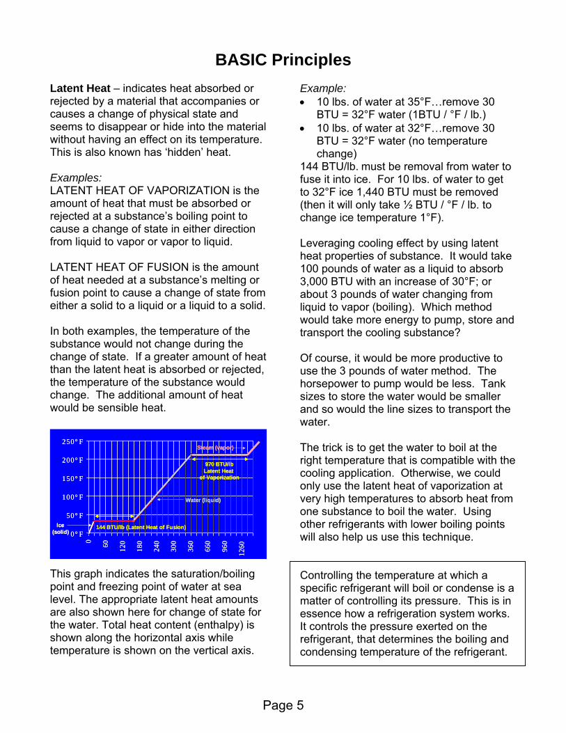
This graph indicates the saturation/boiling point and freezing point of water at sea level. The appropriate latent heat amounts are also shown here for change of state for the water. Total heat content (enthalpy) is shown along the horizontal axis while temperature is shown on the vertical axis.
Example: • 10 lbs. of water at 35°F…remove 30
BTU = 32°F water (1BTU / °F / lb.) • 10 lbs. of water at 32°F…remove 30
BTU = 32°F water (no temperature change)
144 BTU/lb. must be removal from water to fuse it into ice. For 10 lbs. of water to get to 32°F ice 1,440 BTU must be removed (then it will only take ½ BTU / °F / lb. to change ice temperature 1°F). Leveraging cooling effect by using latent heat properties of substance. It would take 100 pounds of water as a liquid to absorb 3,000 BTU with an increase of 30°F; or about 3 pounds of water changing from liquid to vapor (boiling). Which method would take more energy to pump, store and transport the cooling substance? Of course, it would be more productive to use the 3 pounds of water method. The horsepower to pump would be less. Tank sizes to store the water would be smaller and so would the line sizes to transport the water. The trick is to get the water to boil at the right temperature that is compatible with the cooling application. Otherwise, we could only use the latent heat of vaporization at very high temperatures to absorb heat from one substance to boil the water. Using other refrigerants with lower boiling points will also help us use this technique. Controlling the temperature at which a specific refrigerant will boil or condense is a matter of controlling its pressure. This is in essence how a refrigeration system works. It controls the pressure exerted on the refrigerant, that determines the boiling and condensing temperature of the refrigerant.
Page 5

BASIC Principles How does refrigeration work? A simple refrigeration process/system must: • Attract heat from the warm air
surrounding the product • Absorb heat from the air into cooling
media which is cooler than the air • Use change of state to leverage cooling
effect by causing refrigerant to change (from solid to liquid or liquid into vapor)
• Carry heat absorbed into cooling media away from refrigerated area
• Circulate cooled air around product • Absorb heat from product into cooler air
and thereby warming the air • To reuse cooling media, reverse change
of state process (changing it from a liquid to a solid or a vapor to a liquid)
• Cycle continues from start One of the first examples of refrigeration used ice as the refrigerating media. It was called an icebox. • Ice would be delivered daily and placed
in the upper compartment of the icebox to replace melted ice.
• The warm air in the icebox would melt the ice with the ice absorbing its latent heat of fusion (144BTU/lb.).
• Resultant water from the melted ice would drain out of the cabinet.
• Cooled air, which is denser than warmer
air, dropped to the bottom of the icebox where perishable products were stored.
• This air then absorbed heat from the warmer product and rose back to ice compartment as it became warmer and its density decreased.
• It was critical to know how much ice would be needed for the entire day as ice was only delivered once per day and cooling depended on it.
• Iceboxes were sized based on how much ice would melt in them within a 24-hour period.
• Larger iceboxes melted many, many pounds of ice and were rated in tons (2000 lbs.) of ice needed.
• One ton of ice melting over 24 hours would absorb 288,000 BTU (2,000 lbs. X 144 BTU/lb lat. Ht. of Fusion). Using 32°F water for the cooling instead of ice would have required 144 tons or 288,000 lbs. of water.
• This is equivalent to 12,000 BTU/hr (288,000BTU / 24 hours)
• Today, we still refer to 1 ton of refrigeration as 12,000 BTUH.
Compare refrigeration to a man in a boat with a sponge. He uses the sponge to remove unwanted water from his boat as the refrigeration system uses refrigerant to remove the unwanted heat from the cooled space.
And just as he reuses the sponge over and over again, we can also
reuse the refrigerant in a refrigeration system after we remove the
heat it has absorbed.
Page 6

Refrigeration Process In the evaporator, the cool refrigerant absorbs heat from the return-air circulating in the room thus cooling the space. This results in the refrigerant evaporating or boiling from a liquid into a gas or vapor. Normal system design has a minimum of 10°F TD between the refrigerant and the room air temperatures. Example: 35°F room would have 25°F refrigerant boiling temperature (to take advantage of latent heat of vaporization). The refrigerant (in vapor form) needs to reject the heat it has absorbed before it can be recycled back into the process. Next, the evaporated refrigerant is pulled through the suction line and into the compressor where its pressure is increased. Because of the pressure-temperature relationship of the refrigerant, its temperature also increases above that of the 95°F outdoor temperature.
EvaporatorEvaporator
CondenserCondenser
FlowControlCompressor
Cooling Section
Recovery Section
Typically, the refrigerant temperature is raised to be 20-25°F greater than the outdoor temperature. When the high pressure/temperature refrigerant is then circulated inside the condenser, it rejects its heat into the outdoor air and is condensed back into a liquid but at a high pressure and a high temperature. The flow control device regulates or meters the flow of refrigerant back into the evaporator to maintain the proper pressure for the refrigerant to boil at 25°F. It also acts as a pressure trap to maintain desired condensing pressure and temperature. By artificially creating two different pressure conditions, the system controls the boiling and condensing temperatures of the refrigerant. Different refrigerants have different boiling/condensing temperatures and pressure/temperature characteristics.
Page 7

BASIC Principles Only a small part of the cooling system is used to actually perform the cooling job or “cooling effect” which is the entire reason for the system. The rest of the system is used to recover the refrigerant from a gas back to a liquid for reuse by the system. To better understand what happens within the refrigeration process, let’s examine what happens to the refrigerant in each phase of the refrigeration process. Three Conditional States Refrigerant will exist as a liquid or a vapor inside a typical refrigeration system. It will also be in one of three conditional states:
• Saturation – liquid and vapor in contact
• Superheated – only vapor present
• Subcooled – only liquid present
Refrigerant enters the flow control device as a liquid at high pressure and high temperature. As it leaves this device, its pressure and temperature decrease and it immediately begins absorbing heat in the evaporator. This causes the refrigerant to change from a liquid to a vapor. This point is called the saturation or boiling point. In the saturation conditional state, liquid and vapor refrigerant are both present at the same temperature and pressure. Pressure - temperature charts and tables have been developed to indicate the specific saturation temperatures for each particular refrigerant at various pressures. As the saturated refrigerant absorbs more heat, more of the liquid refrigerant boils and is converted into vapor. This occurs until all of the liquid boils off, and only vapor is left.
If the refrigerant vapor is heated above its saturated temperature and liquid is no longer present, it becomes superheated vapor. This is the desired condition of the refrigerant at the outlet of the evaporator. Although it is superheated in relationship to its saturation point, it is cool to the touch. In our example on the previous page, it will be about 35°F leaving the evaporator with approximately 10°F of superheat. As the refrigerant is drawn down the suction line toward the compressor, it absorbs more heat and loses some pressure to become even more superheated. At the inlet to the compressor, it may be another 10°F higher. NO LIQUID REFRIGERANT should be allowed to enter the compressor. We recommend that the refrigerant be a minimum of 20-30°F superheated at the compressor inlet for proper compressor protection against liquid refrigerant. Through the compressor, the refrigerant absorbs more heat and increases in pressure. When it leaves the compressor, its superheat has increased and is at a high temperature and pressure. Typically, it can be 225°F leaving the compressor. Before superheated vapor can be condensed, it must be de-superheated at the beginning of the condenser. It must be first cooled to its saturation point where it will begin to condense into a liquid. As more heat is removed, more of the vapor is condensed until only liquid is left. When the liquid refrigerant is cooled below its saturation temperature, it is subcooled. Pressure losses in the liquid line could cause the refrigerant to reach saturation and “flash” unless it has some subcooling.
Page 8

BASIC Principles In summary, we expect the refrigerant to be in the following physical states for these specified phases of the refrigeration cycle: Saturated Refrigerant – both liquid and vapor are present and in
direct contact with each other – temperature and pressure are linked
together corresponding to values of the refrigerant specific P/T table or chart
where: – in the evaporator and condenser coils
where refrigerant is changing state – in the receiver where liquid and vapor
are both present Superheated Refrigerant – only vapor refrigerant is present – temperature and pressure link is lost
and actual temperature will be above P/T chart or table values where:
– near the outlet of the evaporator coil, through the suction line, through the compressor , through first part of condenser coil
Subcooled Refrigerant – only liquid refrigerant is present – temperature and pressure link is lost
and actual temperature will be below P/T chart or table values
where: – near the outlet of the condenser coil;
through the liquid line; through the flow control device; to the evaporator inlet
How can we determine what physical state the refrigerant is in and to what degree? You must take pressure and temperature measurements and compare to P/T chart or table (a.k.a. saturation chart/table). Measuring Physical State of Refrigerant: 1. Take pressure reading with accurate
gauge at the system location you need to evaluate
°F R-12 R-22 R-502 R-404A-40 11" 0.5 4.1 4.5-20 0.6 10.1 15.3 160 9.2 24 31.1 3320 21 43 52.5 5640 37 68.5 80.5 8560 57.7 101.6 116.4 12680 84.2 143.6 161.2 175100 117.2 195.9 216.2 237120 157.7 259.9 282.7 312.5140 206.6 337.3 262.6
2. From P/T chart or table, determine the saturation temperature value for the pressure measured in previous step
3. Take temperature reading with reliable instrument at the same system location
4. Compare actual temperature reading with the saturation temperature value from step #2
a. If the actual temperature is the same as the saturation value, the refrigerant is saturated
b. If the actual temperature is higher than the saturation value, the refrigerant is superheated by the difference in temperatures
c. If the actual temperature is lower than the saturation value, the refrigerant is subcooled by the difference in temperatures
Caution: be very careful when working with negative numbers to calculate their differences.
Page 9
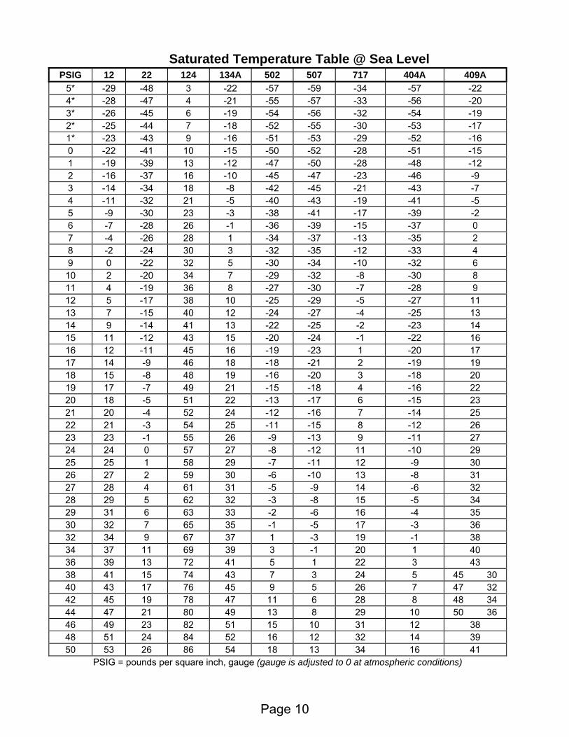
Saturated Temperature Table @ Sea Level PSIG 12 22 124 134A 502 507 717 404A 409A
5* -29 -48 3 -22 -57 -59 -34 -57 -22 4* -28 -47 4 -21 -55 -57 -33 -56 -20 3* -26 -45 6 -19 -54 -56 -32 -54 -19 2* -25 -44 7 -18 -52 -55 -30 -53 -17 1* -23 -43 9 -16 -51 -53 -29 -52 -16 0 -22 -41 10 -15 -50 -52 -28 -51 -15 1 -19 -39 13 -12 -47 -50 -28 -48 -12 2 -16 -37 16 -10 -45 -47 -23 -46 -9 3 -14 -34 18 -8 -42 -45 -21 -43 -7 4 -11 -32 21 -5 -40 -43 -19 -41 -5 5 -9 -30 23 -3 -38 -41 -17 -39 -2 6 -7 -28 26 -1 -36 -39 -15 -37 0 7 -4 -26 28 1 -34 -37 -13 -35 2 8 -2 -24 30 3 -32 -35 -12 -33 4 9 0 -22 32 5 -30 -34 -10 -32 6
10 2 -20 34 7 -29 -32 -8 -30 8 11 4 -19 36 8 -27 -30 -7 -28 9 12 5 -17 38 10 -25 -29 -5 -27 11 13 7 -15 40 12 -24 -27 -4 -25 13 14 9 -14 41 13 -22 -25 -2 -23 14 15 11 -12 43 15 -20 -24 -1 -22 16 16 12 -11 45 16 -19 -23 1 -20 17 17 14 -9 46 18 -18 -21 2 -19 19 18 15 -8 48 19 -16 -20 3 -18 20 19 17 -7 49 21 -15 -18 4 -16 22 20 18 -5 51 22 -13 -17 6 -15 23 21 20 -4 52 24 -12 -16 7 -14 25 22 21 -3 54 25 -11 -15 8 -12 26 23 23 -1 55 26 -9 -13 9 -11 27 24 24 0 57 27 -8 -12 11 -10 29 25 25 1 58 29 -7 -11 12 -9 30 26 27 2 59 30 -6 -10 13 -8 31 27 28 4 61 31 -5 -9 14 -6 32 28 29 5 62 32 -3 -8 15 -5 34 29 31 6 63 33 -2 -6 16 -4 35 30 32 7 65 35 -1 -5 17 -3 36 32 34 9 67 37 1 -3 19 -1 38 34 37 11 69 39 3 -1 20 1 40 36 39 13 72 41 5 1 22 3 43 38 41 15 74 43 7 3 24 5 45 30 40 43 17 76 45 9 5 26 7 47 32 42 45 19 78 47 11 6 28 8 48 34 44 47 21 80 49 13 8 29 10 50 36 46 49 23 82 51 15 10 31 12 38 48 51 24 84 52 16 12 32 14 39 50 53 26 86 54 18 13 34 16 41
PSIG = pounds per square inch, gauge (gauge is adjusted to 0 at atmospheric conditions)
Page 10

Saturated Temperature Table @ Sea Level PSIG 12 22 124 134A 502 507 717 404A 409A
52 55 28 88 56 20 15 35 17 43 54 57 29 90 57 21 16 37 19 45 56 58 31 91 59 23 18 38 20 46 58 60 32 93 60 24 19 40 22 48 60 62 34 95 62 26 21 41 23 50 64 65 37 98 65 29 24 44 26 53 68 68 40 101 68 32 27 46 29 56 72 71 42 104 71 34 29 49 32 31 58 76 74 45 107 73 37 32 51 34 33 61 80 77 48 110 76 40 34 53 37 36 64 85 81 51 114 79 43 37 56 40 39 67 90 84 54 117 82 46 40 58 42 42 70 95 87 56 120 85 49 43 61 45 44 73 100 90 59 123 88 51 46 63 48 47 76 105 93 62 126 90 54 48 66 50 79 110 96 64 129 93 57 51 68 52 82 115 99 67 132 96 59 53 70 55 84 120 102 69 135 98 62 56 73 57 87 125 104 72 138 100 64 58 75 59 89 130 107 74 140 103 67 60 77 62 92 135 109 76 143 105 69 62 79 64 94 140 112 78 145 107 71 64 81 66 96 145 114 81 148 109 73 67 82 68 99 150 117 83 150 112 75 69 84 70 101 155 119 85 152 114 77 71 86 72 103 160 121 87 154 116 80 73 88 74 105 165 123 89 157 118 82 74 90 76 107 170 126 91 159 120 83 76 91 78 109 175 128 92 161 122 85 78 93 80 111 180 130 94 163 123 87 80 95 82 113 185 132 96 165 125 89 82 96 83 115 190 134 98 167 127 91 83 98 85 117 195 136 100 169 129 93 85 99 87 119 200 138 101 171 131 95 87 101 88 121 205 140 103 173 132 96 88 102 90 123 210 142 105 175 134 98 90 104 92 124 220 145 108 178 137 101 93 107 95 128 230 149 111 182 140 105 96 109 98 131 240 152 114 185 143 108 99 112 101 134 250 156 117 188 146 111 102 115 104 137 260 159 120 192 149 114 105 117 107 141 275 163 124 196 153 118 109 121 111 145 290 168 128 201 157 122 112 124 115 149 305 172 132 205 161 126 116 128 118 153 320 177 136 209 165 130 120 131 122 157 335 181 139 213 169 133 123 134 126 161 350 185 143 217 172 137 126 137 129 165
Page 11

Refrigeration Cycle
Evaporator
Compressor Condenser
Flow ControlThis diagram indicates the four basic components needed for a refrigeration system. There are many different types of these components. Each variation has certain strengths and weaknesses, and which one is to be used depends on the particular design criteria and specific application requirements. Let’s take a closer look at each of the four basic components of a simple refrigeration system. A few of the most popular types are listed below. Compressor – Heart of the System Reciprocating – This is the most widely used of all types of compressors. It uses a
piston that moves up and down inside a hollow cylinder to compress the refrigerant (much like a typical car engine works).
There are two types valve configurations of reciprocating compressors:
• Reed – with intake and exhaust tensioned, straight steel reeds
• Discus – with intake tensioned, circular steel reed and a spring retained solid discharge valve
These compressors can also be of hermetic (or welded) design or semi-hermetic (or bolted-construction) design. The latter version can also have either open or direct
drive motor configurations and gas or air cooled motor designs. Scroll – This type compresses the refrigerant using orbiting and fixed scrolls, which squeeze the gas into 6 chambers, which decrease in volume as the scroll rotates. The normal configuration uses a hermetic design. Centrifugal – The centrifugal compressor increases the refrigerant pressure by throwing it at high velocity (like an ordinary house fan throws air) using a rotating impeller inside a stationary housing.
Page 12

Evaporator
Compressor
Metering Device
High Side
Low Side
Condenser
Compressor
ompression ratio indicates how much ressure change the compressor needs to
rting
: absolute ischarge pressure = 260 psig +14.7 psi or
=
ompressors. The lower the temperature,
r
ssors specially designed withstand high-ratio operation. They may
Regardless its type, all compressors must perform the following three jobs: • Create the required pressure difference 25°F
120°F
260 psig49 psig
• Pump sufficient volume of refrigerant • Accommodate the refrigerant used Create the required pressure difference
The refrigeration system maintains two separate pressurized sections. In one section the pressure is kept low enough for the refrigerant to boil in the evaporator and absorb heat from the air-cooling the room at a temperature desired for this particular application. This low-pressure section of the system is called the “low side” for its low temperature and low-pressure refrigerant. In the other section, pressure is kept high enough for the refrigerant to condense back into a liquid in the condenser, that is using higher temperature air or water to absorb the heat from the refrigerant. This section is known as the “high side” of the system for it higher temperature and pressure. Each section’s desired/design pressure is dependent upon the required operating temperatures in the evaporator and in the condenser and also on the refrigerant used in the system. The compressor creates the pressure different between these two sections by its suction action reducing the evaporator pressure and it’s pressurizing the discharge gas entering the condenser. Using our previous example: +35°F room temperature with desired refrigerant boiling at +25°F would require 49 psig pressure in the evaporator for R-22 refrigerant. Using +95°F outdoor ambient air temperature and 25°F design TD, an air-cooled condenser pressure would need to be 260 psig for 120°F condensing temperature with R-22.
Cpcreate in a system. This is found by dividing its absolute discharge pressure by its absolute suction pressure. Convepsig (pounds per square inch, gauge) to psia (pounds per square inch, absolute) is just adding local atmospheric pressure topsig. At sea level you would add 14.7 psi topsig to covert psig to psia. For our example at sea leveld275 psia, and absolute suction pressure49 psig +14.7psi or 64 psia. Compression ratio would be ≈ 4.3 (275 psia ÷ 64 psia). Higher compression ratios are harder on cthe higher the compression ratios requiredresulting in tougher and less efficient compressor operation. Some designers seta ratio limit of 10 to 1 or even 7 to 1 fobetter reliability. There are compretohave extra piston rings, tighter tolerances and more elaborate cooling systems to compensate for the more demanding conditions associated with higher ratios.
Page 13

C sor ompres
ump sufficient volume of refrigerant
g
herefore, larger compressor pumping
ssor p
or a 1 ton (12,000BTUH) application, a
is also important to understand that the
y
a low temperature compressor were on,
e
ccommodate the refrigerant used the
Construction materials must also be onsidered to accommodate the refrigerant.
.
ants.
y their operating range, by refrigerant, and
ompressor Control Devices
vices, hich are used to protect the compressors.
falls
• tlet pressure
• indings
• il ls below a set point value
h
h
P
he amount of refrigerant volume needed Tfor a particular system depends on its operating temperature. Lower operatintemperatures require more refrigerant gasvolume to be in circulation to do the job. Tcapacities are needed for the lower temperature applications. A comprerunning at a constant, fixed RPM can pumso much refrigerant. This amount may be sufficient for one temperature but not for another, lower temperature. Fspecific compressor may be able to cool agiven load at +40°F suction temperature. The same compressor may only be able tohandle a load of 6,000BTUH or ½ ton at 0°F suction temperature. Itload on the motor driving the compressor changes with temperature. Since the compressors running at higher suctiontemperature have higher capacities, therequire larger drive motors. Ifapplied on a high temperature applicatithe compressor motor could be greatly “overloaded”. Horsepower and tonnagare not equal or synonymous. A
ompressors must be compatible with Crefrigerant being used in the system. The refrigerant effects the compressor design as it pertains to the size of valve ports, thestrength of valve springs, or the design of the cooling system.
cSome refrigerants or their associatedlubricant oils could attack certain materials used in some compressor constructionNew materials, which are more compatible, need to be used. Actual thickness of materials or different alloys may need to be considered for higher-pressure refriger Compressors are often classified or sized bby capacity. Typical suction temperature ranges are classified and indicated as: • H = high • M or C = medium or commercial • L = low • XL = extra or ultra low C There are many safety control dewMany of these are optional or special. • Low Pressure Control (LPS) – shuts off
the compressor, if its inlet pressurebelow a set point value High Pressure Control (HPS) – shuts off the compressor, if its ougoes above a set point value Internal Overloads – shuts off the compressor, if internal motor wget too hot Oil Pressure Control – shuts off, if the opressure fal
• Discharge Line Thermostat – shuts off, if discharge line temperature gets too hig
• Compressor Module – shuts off, if amps or temperatures exceed proper limits
• Phase Loss Monitor – shuts off, if power phase is incorrect or voltage is too low
• Demand Cooling Module – shuts off, if discharge gas temperature gets too hig
Page 14

Flow Co trol All flow control devices must regulateflow of refrigerant to do the following jobs:
n
ct as pressure trap against high side
nction, it must create two separate w
at t
egulate desired boiling point pressure
ls,
rough the vaporator coil it absorbs more and more
por.
ny additional heat absorbed by the
ll then .
The rate at which the refrigerant boils will
e mount of refrigerant available. To properly
te
ly st its
ofrigerant needed for the load,
he liquid refrigerant may not boil ff. This liquid refrigerant could pass
f
vaporator. The heat transfer efficiency of
n d allow
lly active boiling of refrigerant through
r r
hould be present at the evaporator outlet r
n the
• Act as pressure trap for the high side Regulate desired boiling point pressure•
• Maintain proper superheat for protectio A In order for the refrigeration system to fusections with different pressures to allothe refrigerant to boil and to condensethe desired temperatures/pressures. Theflow control device acts as a pressure trapto help maintain the high side at the correcpressure. Without this device in place, the compressor alone would not be able to maintain the pressure differences required. R
When the high-pressure liquid refrigerant asses through the flow control device, it is p
immediately exposed to lower pressures and tremendous temperature differences. Thus, some of the refrigerant instantly boichanging to a vapor, and expands. This is why many of these flow control devices are called “expansion” valves. As the refrigerant passes theheat causing more liquid to boil into vaSo long as there is liquid present, the heatbeing absorbed will not raise the refrigerant temperature but will instead be used to continue vaporizing the liquid refrigerant. When the last trace of liquid is boiled off, arefrigerant will increase its temperature above its saturated temperature. It wibecome a superheated refrigerant vapor
depend upon the amount and degree of heat load present in the evaporator and thamaintain the pressure for the desired boil point, the flow control device must regulathe flow for varying load conditions and to constantreadjuposition. If the flow camount of resome of t
Cooling Load
ntrol device “over-feeds” the
othrough the evaporator, into the suction line, and be drawn into the compressor where it might cause severe damage. On the other hand, the “under-feeding” orefrigerant could result in the refrigerant boiling off into a vapor too soon in the ethe evaporator and system performance would suffer under this condition. Maintain proper superheat for protectio
roper feeding of refrigerant shoulPfualmost the entire length of the evaporator or optimum heat transfer performance. f However, no liquid refrigerant should be permitted to leave the evaporator and entethe suction line. Only superheated vaposto help prevent liquid refrigerant from evereaching the compressor.
Page 15

Page 16
Diaphragm
Inlet(liquid)
Outlet(mixture)
Flow Control
SensingBulb
SuperheatSpring
Diaphragm
Inlet(liquid)
Outlet(mixture)
SensingBulb
SuperheatSpring
Evaporator
ThermostaticExpansion Valve
8:00 4:008:00 4:00
12
9 3
6
Hand Valve – This simple, low cost form of flow control
atic controls in irs.
very lementary and uses a length of small
sing on
Major advantage is that it allows system
ressures to equalize during the off cycle.
frigerant system harge to prevent compressor overloading
n
ion Valve – It is a pressure-
to e
e varying
ring ods the
static Expansion Valve (TEV) – It senses the conditions of the refrigerant
low to maintain a preset value r superheat at the evaporator outlet.
e evaporator by
External equalized: sense refrigerant pressure and its temperature at the evaporator outlet by attaching a sensing
essure on line.
ntial
ings for correct and reliable operation of the TEV.
is seldom used because it must be constantly adjusted to compensate for changingload conditions. It may be used in large systems as a bypass valve around automcase of failure or during repa Capillary Tube – This method isediameter tubing to control flow by impoa restriction or pressure drop. It is usedsmall unitary equipment such as window air conditioners, domestic refrigerators and commercial refrigeration cases (reach-ins).
pThis allows for use of low starting torque motors on compressors. Disadvantage is critical recand possible liquid flood-back to the compressor during the off cycle. Also, it is not much better than the hand valve ireacting to varying load conditions.
Automatic Expans
reducing device actuatedkeep evaporator pressurconstant and does fluctuatsomewhat to match load conditions. Used infrequently as it tends to starve the system duheavy loads and flosystem during light loads.
inside the evaporator and automatically adjusts the f
Thermo
fo Internal equalized: senses refrigerant pressure at the TEV and the temperature of refrigerant leaving thattaching a sensingbulb to suction line.
bulb and prtap to sucti
Proper sensing bulb mounting is esseto assure accurate temperature read

Flo
Page 17
w Control When evaporators are large enough for TEVs, they also have sufficient pressure losses though them to require the use of distributors for proper feeding of their refrigerant circuits. Capillary tubes, automatic expansion valves and internal equalized TEV should not be used on evaporators with multiple refrigeration circuits.
istributors are designed to evenly feed not o
ow o be
ange to suite different conditions.
ent conditions.
Venturi Type
loat Control – This device is used with ome flooded evaporators and has a ball at floats on the refrigerant to indicate the vel of refrigerant in the evaporator. If the vel gets too high or too low, the float rises
and susceptible to mechanical
tronic – These devices are tuated from a controller with
ensors to measure superheat conditions of e refrigerant leaving the evaporator. The lectric valve uses a motor to adjust a stem n a seat to regulate flow. The electronic
ulates flow by opening and closing le times and at varying time periods.
g stem ve
e
unfamiliar set up steps for technicians, and different parts to troubleshoot and replace when failures occurs.
Dmultiple circuited evaporators. They are designed to regulate flow of refrigerant asflow control devices perform. There are twbasic types of distributors: Orifice Type: uses different nozzles sizedfor the refrigerant, temperatures, and flof the application. It has the flexibility table to ch Venturi Type: uses a specially machined housing designed for a specific refrigerant, temperature and flow conditions. It is moreefficient than the orifice type, but cannot be easily changed to suit differ Orifice Type
Fsthleleor falls and adjusts a valve, which controls the flow of liquid refrigerant. Flooded systems are more efficient than direct
on. However, they are more expansicomplexfailures and leaks with high risk of flooding.
Electric/Eleclectrically ace
stheovalve regmultip There are many advantages to using real logic to control refrigerant flow includinbetter tools to monitor and diagnose syoperations. Drawbacks include sensiticomponents, which may be more delicatthan conventional, more system complexity,
Outlet Inlet
Evaporator

Evaporator
This major component is in the low side of the refrigeration system where the boiling of
efficient, economical and used in all sizes of refrigeration systems.
• Flooded – Liquid refrigerant fills most of the evaporator coil like a bucket. It is very efficient. Recirc versions of this type overfeed the evaporator with refrigerant and have liquid refrigerant actually leaving the coil. Flooded coils are used in cooling other liquids, such
The tubes v s,
interescou Ext
Airs
of ais tconresIncby com
nother technique is to increase the airflow ver the coil tubes (and fins) with a fan or lower. This also increases convection urrents to improve heat transfer. aution must be used not to blow o much air over the coil, which
ould blow condensate off the coil
. n
is similar and has its wn special challenges according to the pe of fluid or solution being used. Basic
techniques of increasing turbulence and decreasing pressure drop also apply here.
refrigerant circuiting ove this situation
less work on the ss pressure drop.
hese
be
s).
the refrigerant occurs and produces the cooling effect. There are several types of evaporators or coils in use:
• Direct Expansion – Refrigerant is completely boiled off in the evaporator with no liquid refrigerant at the coil outlet. The circuit is said to be “dry” due to lack of refrigerant liquid. This type is
as water or brine and are typically foundin larger refrigeration systems.
Evaporator coils utilize tubes to contain therefrigerant with air or fluids being circulatedn the outside of the tubes. o
ha e two heat transfer resistant surfacernal and external. To overcome these istances or surface films, various nter measure methods are available.
ernal “surface film”
de surface film is iespecially difficult to overcome. The nature
ir, like most gases, o be a poor ductor with great istance to heat flow. reasing the amount of air surface area attaching fins or collars to the tubes can pensate for this surface film.
AobcCtocand in the space and onto product. Increasing the turbulence in the air stream over the coil will also improve its heat flowThis can be accomplished using external fiwith different corrugations, edges, lancing, turning vanes, and louvers. Fluid-side surface film oty
Internal “surface film”
On the inside of the evaporator, heat transfer can be improved by increasing thewetting of the tube walls with refrigerant. This an be challenging c
with the constant hanging of the c
refrigerant from liquid to vapor at the tube walls. Multiple is one technique to imprand also imposecompressor through le Other measures to increase the turbulenceof the refrigerant will also increase the wetting effect on the tube walls. Tinclude turbulators (elongated springs inside the tubes), smaller tubing diameters(to increase velocities), and enhanced tu(rifling or grooving of inside surface
Page 18

EvaAll evaporators must meet the following hree requirements
po
:
e temperatures n and the amount
of heat load, there is a particular internavolume required for the refrigerant to bo
internal volume, the a equirem
tion system will fail to do its nternal volume will require
ant flow to maintain the erature/pressure and tem may “short cycle”
versized capacity.
und es
.
e
ce, to
.
he caustic conditions.
e air. It is consists
t
on will determine
rator Proper surface design Sufficient surface must be available in the evaporator for heat to pass easily and quickly into the refrigerant inside the tubes. The materials used must be compatible
ith the application requirements.
t • Sufficient internal volume • Minimum pressure drop • Proper surface design Sufficient internal volume There must be enough internal volume to accommodate the amount of refrigerant required to meet the cooling demands
laced on the system. Based on the prefrigerant being used, thequired for the applicatior
l il
and expand at the required temperature.
there is not enoughIfhe t transfer rand the refrigera
h i
ents will not be met
job. Too mucgreater refriger
opr per boiling tempthe refrigeration sys
ue to od
inimum pressure drop M The refrigerant must be allowed to flow through the evaporator with a minimum amount of pressure drop. For every poof pressure drop the refrigerant experiencpassing through the evaporator, the system compressor has to raise the pressure of the refrigerant to offset for the condenser cycle
ach refrigerant at a particular temperaturEand pressure has an optimal allowable pressure drop range. Evaporators must bedesigned to stay within that allowable range through use of multiple circuiting methods.
Cooling coils This simple but very popular design is for bsorbing heat from
w If the application is low temperature and frost will build up on the evaporator surfathe fins-per-inch should not high enoughcause “plugging” of the coil with heavy frostApplications with the evaporator located inside a caustic or acidic environment will require the use of material resistive to t
athof a bundle of tubes razed together to b
form a serpentine circuit or circuits through which refrigeranflows. Air flows over the outside of this coil, which may also have external surface fins to enhance the heat transfer from the air into the tubes.
ome of this style of coil may also have a Sblower or a fan to force air over the coil. These are sometimes called induce air or induced circulation coils. Convection coils do not use fans but instead rely on natural convection currents for air circulation.
emands of the applicatiDwhich evaporator style is the most appropriate or proper to get the job done.
Page 19
Evaporator
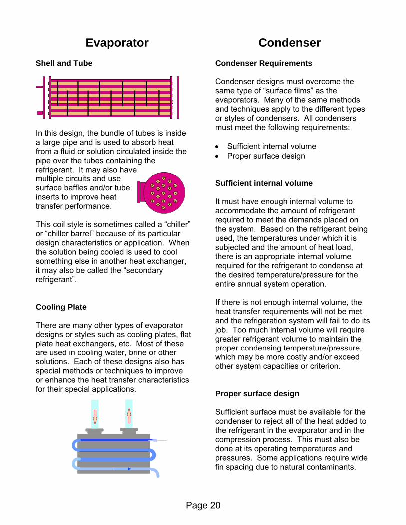
undle of tubes is inside large pipe and is used to absorb heat om a fluid or solution circulated inside the
bes containing the frigerant. It may also have
se tube t
etimes called a “chiller” cause of its particular
the solution being cooled is used to cool
Cooling Plate
ther types of evaporator such as cooling plates, flat
teristics
It must have enough internal volume to accommodate the amount of refrigerant required to meet the demands placed on the system. Based on the refrigerant being used, the temperatures under which it is subjected and the amount of heat load, there is an appropriate internal volume required for the refrigerant to condense at the desired temperature/pressure for the entire annual system operation.
olume, the not be met
and the refrigeration system will fail to do its
the nsing temperature/pressure,
hich may be more costly and/or exceed ther system capacities or criterion.
to
e at it
Condenser
multiple circuits and usurface baffles and/orinserts to improve heatransfer performance. This coil style is somor “chiller barrel” bedesign characteristics or application. When
Condenser Requirements Shell and Tube
In this design, the bafrpipe over the ture
something else in another heat exchanger, it may also be called the “secondary refrigerant”.
If there is not enough internal vheat transfer requirements will
There are many oesigns or styles d
plate heat exchangers, etc. Most of these are used in cooling water, brine or other solutions. Each of these designs also has special methods or techniques to improve or enhance the heat transfer characfor their special applications.
job. Too much internal volume will require greater refrigerant volume to maintainproper conde
Condenser designs must overcome the same type of “surface films” as the evaporators. Many of the same methods and techniques apply to the different types or styles of condensers. All condensers must meet the following requirements: • Sufficient internal volume • Proper surface design Sufficient internal volume
wo Proper surface design Sufficient surface must be available for the condenser to reject all of the heat added the refrigerant in the evaporator and in the compression process. This must also be don s operating temperatures and pressures. Some applications require wide fin spacing due to natural contaminants.
Page 20
Conden
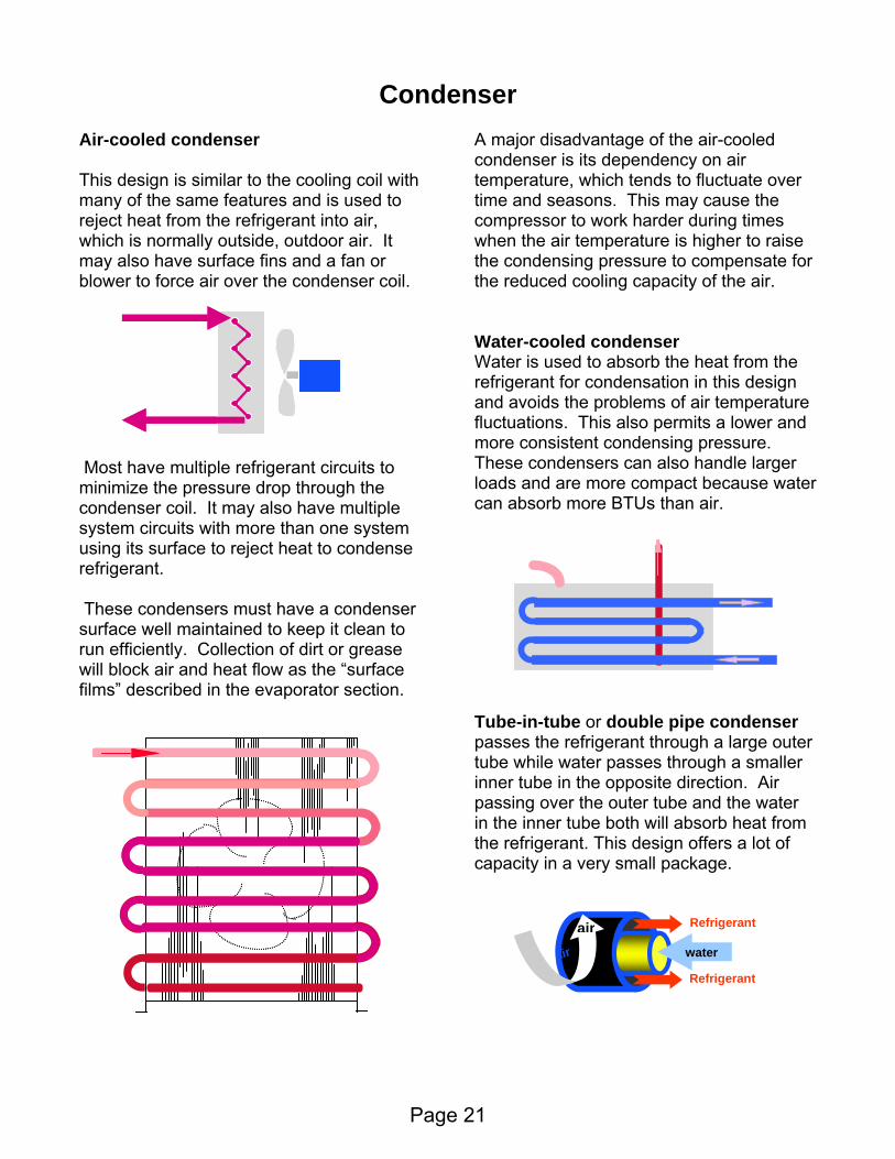
ir-cooled condenser
his design is similar to the cooling coil with any of the same features and is used to ject heat from the refrigerant into air, hich is normally outside, outdoor air. It ay also have surface fins and a fan or lower to force air over the condenser coil.
o n rough the n ave multiple s han one system
sing its surface to reject heat to condense
ser o
uate over
the frigerant for condensation in this design
of air temperature rmits a lower and
n-tube or double pipe condenser through a large outer
r
ser
These condensers must have a condensurface well maintained to keep it clean trun efficiently. Collection of dirt or greasewill block air and heat flow as the “surface films” described in the evaporator section.
A major disadvantage of the air-cooled condenser is its dependency on air emperature, which tends to fluct
A Tmrewmb
ost have multiple refrigerant circuits t M
mi imize the pressure drop th hco denser coil. It may also
y tem circuits with more tsurefrigerant.
tube while water passes through a smalleinner tube in the opposite direction. Air assing over the outer tube and the water
ttime and seasons. This may cause the compressor to work harder during times when the air temperature is higher to raise the condensing pressure to compensate for the reduced cooling capacity of the air. Water-cooled condenser
ater is used to absorb the heat fromWreand avoids the problems luctuations. This also pefmore consistent condensing pressure. These condensers can also handle larger loads and are more compact because watercan absorb more BTUs than air.
Tube-ipasses the refrigerant
pin the inner tube both will absorb heat fromthe refrigerant. This design offers a lot of capacity in a very small package.
water
Refrigerant
Refrigerant
air
air
Page 21

Conden
s liquid.
be riodically cleaned to remove deposits,
hich settle out of the water and reduce ng capacity.
cooutdoor air and reused. Without the w
nt
ible and tent cooling techniques to condense the frigerant. It is like a water tower and
, w over
e tubes. Make-up water is also needed to place the small amount of water that
vaporates.
to ssen the corrosive properties of the fluid
.
g conditions.
ser
Water towers allow water from water-
Evaporative condenser
his style of condenser uses sens
Shell and tube condenser has the hot refrigerant dropping into the top of the shell surrounding the water being circulated in the tubes. The shell acts as the condenserreservoir or receiver for the condensed efrigerant, which is pulled from the bottom r
a
Tubes of water-cooled condenser must pewheat transfer thereby reduci
oled condensers to be cooled by the ater
towers sometimes called “cooling towers”, city water would have to be used in the condensers, which is becoming more and more expensive to use. The cooling towers use sensible and late
cooling as it absorbs it latent heat of
Tlarecondenser combined. Refrigerant passes through tubes in a coil with water and air circulating over the outside of the coil. Some of the water evaporates and cools the remaining water, which cools the refrigerant along with the outdoor air. Like a water or cooling tower
ater in the sump is pumped to flowthree
Water treatment and regular maintenance are necessary for all the water-cooled andevaporative condensers styles. Some hemical additives may include inhibitorscooling techniques to cool the water. As
the water flows from the top of the tower over a series of baffles, outdoor air is blown across the baffles sensibly cooling the water while a small portion of the water evaporates and provides additional latent
clesolutions. Also, glycol may be needed to prevent freezing during very low ambient conditionsSpecial precautions may require seasonal operation changes to protect sumps from freezing, such as adding glycol or running
em “dry” during freezin
vaporization from the water to evaporate.
th
Page 22

Accesso
Solenoid Valve
ries &
This is an electrically actuated valve in the liquid line, which controls the flow of refrigerant to the flow control device. It is an open or closed valve and does not modulate. This device has an iron core plunger which
and an electrical olenoid coil. It is normally closed when the
direction of refrigerant flow through the is reversed, the refrigerant up against the plunger
preventing the valve from closing.
,
alve. With the flow of
es are available with flare or weat connections and with optional anual lift stem feature. The manual lift
s not need a solenoid valve cluded with its installation.
in use or needed in circulation. The amount of refrigerant needed in circulation may vary as the load conditions fluctuate. It can also be used to hold the entire system’s refrigerant charge during
cedures. A valve at the needed to pump the entire
charge into the receiver and hold it there,
The typical design of the receiver includes a dip tube, which extends to within ½” of the bottom of the receiver to maintain a liquid seal for pulling only liquid into the liquid line when needed. Since both liquid and vapor refrigerant are present, the refrigerant is at
Options
One of the most important fe
Solenoid valv
seats into the valve orifice scoil is de-energized, and the forces of gravity and an optional spring seat the plunger.
atures is the ates the proper maintenance pro
receiver outlet isdistinctive arrow, which indic
valve. If the flow pressure will push
Normally it is wired in series with the room thermostat. When the room temperature is satisfied, the thermostat contacts open andthe solenoid valve loses power and closesshutting off the flow of refrigerant to theexpansion vrefrigerant shut off, the compressor will continue to operate until the pressure falls below the cut-out set point of the low pressure switch/control (LPS).
smstem allows the valve to be manually opened in an emergency. The electric or electronic expansion valve closes as secure as a solenoid valve and normally doein Receiver This is a liquid refrigerant storage tank in the liquid line to contain refrigerant not
saturation in the receiver. Horizontal and vertical versions of the receiver are available.
Page 23
Accessor
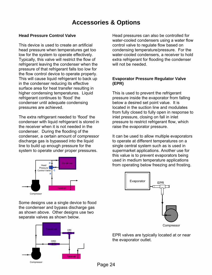
Head Pressure Control Valve This device is used to create an arthead pressure when temperatures get tolow for the system to operate effectively. Typically, this valve will restrict the flowrefrigerant leaving the condense
ies & ns
ificial o
of r when the
ressure of that refrigerant falls too low for
ck up
in tures. Liquid
frigerant continues to ‘flood’ the
to ‘flood’ the ondenser with liquid refrigerant is stored in e receiver when it is not needed in the
condenser. During the floodcondenser, a certain amountdischarge gas is bypassed into the liquid
for the ystem to operate under proper pressures.
gas
o below.
For the ater-cooled condensers, a receiver to hold
nser
PR)
hich vaporator pressure.
allow multiple evaporators to operate at different temperatures on a
for
g.
Optio
pthe flow control device to operate properly.This will cause liquid refrigerant to bain the condenser reducing its effective surface area for heat transfer resultinghigher condensing temperarecondenser until adequate condensing pressures are achieved. The extra refrigerant needed cth
ing of the of compressor
It can be used to
line to build up enough pressures
Some designs use a single device to floodthe condenser and bypass discharas shown above. Other designs use twseparate valves as shown
Head Pressure
Control Valve
Head pressures can also be controlled forwater-cooled condensers using a water flowcontrol valve to regulate flow based on condensing temperature/pressure.wextra refrigerant for flooding the condewill not be needed. Evaporator Pressure Regulator Valve (E This is used to prevent the refrigerant pressure inside the evaporator from fallingbelow a desired set point value. It is located in the suction line and modulates from fully closed to fully open in response toinlet pressure, closing on fall in inlet pressure to restrict refrigerant flow, wraise the e
single central system such as is used in supermarket applications. Another use this value is to prevent evaporators being used in medium temperature applications from operating below freezing and frostinCondenser
Receiver
Compressor
D
CR
ge
EPR valves are typically located at or near the evaporator outlet.
CondenserCondenser
Receiver
Compressor
ORI
ORD
EvaporatorEvaporator EPR
Compressor
Page 24

AccessoriCrankcase Pressure Regulator Valve (CPR) – Holdback Valve This valve operates similar to an EPR and
used to limit its co
es &
mpressor’s refrigerant ressure from rising above a desired set
n
e to its outlet pressure, closing on
an fully
e not removed or ltered, they can plug small opening in the
system (such as TEV or oil “pick-up” in the compressor crankcase or sump) and cause other system inefficiencies. Filter-driers have a shell filled with filtering material and desiccant or drying agent and may have flare or sweat type connections. The fill material can be a porous block form or loose fill type and be hermetically sealed or “replaceable core” configuration.
system with new
Options
Filter-Drier
his device is located in the liquid line and
isppoint value. Located in the suction line, itmodulates from fully open to fully closed iesponsr
rise in outlet pressure to prevent the compressor from overloading.
Hot Gas Bypass Valve
Tis used to filter out large contaminants and moisture left in the system at the time of
stallation. If these arinfi
Hot gas bypass valves are located in a bypass line between the suction and the compressor discharge lines and cmodulate in response to outlet (suction) pressure, opening on fall of downstream pressure. This valve is used to maintain a desired minimum suction pressure during times when the compressor is running at very low load conditions.
Suction Filter
This filter is used to protect the compressor from contaminants and is located in the suction line just ahead of the compressor. It may be a sealed or replaceable core type similar to those of the filter-drier with either flare or sweat type connections.
It is considered good practice to replace all filters and filter-driers in afilters or filter-drier each time the system is opened. This may require use of specialfilters and multiple replacements to clean up after a compressor “burn-out”.
EvaporatorEvaporator
Compressor
CPR
EvaporatorEvaporator
HGBP
Compressor
Page 25
Accessor
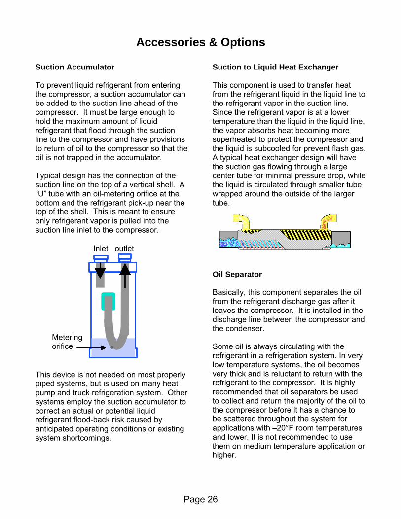
Suction Accumulator
ies &
To prevent liquid refrigerant from entering the compressor, a suction accumulator can be added to the suction line ahead of the compressor. It must be large enough to hold the maximum amount of liquid refrigerant that flood through the suction line to the compressor and have provisions to return of oil to the compressor so that the oil is not trapped in the accumulator. Typical design has the connection of the
n the top of a vertical shell. A ” tube with an oil-metering orifice at the
This device is not needed on most properly piped systems, but is used on many heat pump and truck refrigeration system. Other systems employ the suction accumulator to correct an actual or potential liquid refrigerant flood-back risk caused by anticipated operating conditions or existing
uction to Liquid Heat Exchanger
t is used to transfer heat om the refrigerant liquid in the liquid line to
t flash gas. typical heat exchanger design will have
Oil Separator Basically, this component separates the oil from the refrigerant discharge gas after it
ressor. It is installed in the tween the compressor and
the condenser.
e ry
hly commended that oil separators be used
to
n or
Options
suction line o“Ubottom and the refrigerant pick-up near the top of the shell. This is meant to ensure only refrigerant vapor is pulled into the suction line inlet to the compressor.
system shortcomings.
Some oil is always circulating with threfrigerant in a refrigeration system. In velow temperature systems, the oil becomes very thick and is reluctant to return with the refrigerant to the compressor. It is hig
S This componenfrthe refrigerant vapor in the suction line. Since the refrigerant vapor is at a lower temperature than the liquid in the liquid line,the vapor absorbs heat becoming more superheated to protect the compressor and the liquid is subcooled for prevenAthe suction gas flowing through a large center tube for minimal pressure drop, whilethe liquid is circulated through smaller tube wrapped around the outside of the larger tube.
leaves the compdischarge line be
reto collect and return the majority of the oilthe compressor before it has a chance to be scattered throughout the system for applications with –20°F room temperatures and lower. It is not recommended to use them on medium temperature applicatiohigher.
Inlet outlet
Metering orifice
Page 26

Accessories &
il separators can use a series of baffles nd other velocity reduction techniques to eparate the oil into a collection chamber. rom there, the oil is returned to the ompressor by means of a float system to ense the oil level in the chamber. The ery best of separators is not 100% ffective in separating the oil. If a system is gging oil, an oil separator will not cure the ituation, but may only delay the inevitable.
dequately charged. Foaming and ubbles normally indicate shortage of
restriction in the liquid line.
ning.
Options
OasFcsvelos A small solenoid valve may be needed to prevent oil from migrating into the compressor crankcase during off cycles. Many separators are also heated and insulated when located inside outdoor condensing unit.
Sight Glass/Moisture Indicator This component allows visual observation of refrigerant flow in the liquid line and may be used to determine if the system has een ab
brefrigerant, or a A moisture indicator incorporated in this device provides a means of determining if too much moisture has entered the system. It will warn the observer when the filter/drier needs to be serviced to keep the system dry” and functio“
Page 27

Review♦ How much heat is required to raise 100 pounds o
__________________________ BTU ♦ The heat that changes the physical state of a
_____________ heat.
What is a ton of refrigeration? ___________
♦ What is the purpose of a thermostatic Expans a. control liquid line temperature b. meter refrigerant to evaporator c. create temperature drop d. all of the above
♦ T.D. in refrigeration means? (select answer from the list) a. thermal device b. temperature difference c. touch down d. thermo-dynamics
♦ What is the purpose of superheat in an evaporator? _________________________ ________________________________________________________________ ♦ What are two (2) types of condensers? __________________ ________________ ♦ R-12 gauge reads 15 psig, and measured temperature is 0°F (at sea level). The refrigerant is in what physical state? __________________________________ ♦ Where is refrigerating done in the system? ________________________________ ♦ Refrigerant is superheated entering and leaving what key component? ________________________ ♦ If the gauge pressure equals the equivalent temperature on a temperature pressure
table/chart, the refrigerant is _______________________________.
f water from 70°F to 120°F at sea level?
substance is called …
♦ ______________________________
ion valve? (select answer from the list)
Page 28

Glossary of basic terms related to Commercial Refrigerationer
ccumulator: A shell placed in the suction line just ahead of the compressor for separating liquid cause harm.
ir Bo equipment such as steam radiator, which prevents maximum heat transfer or air trapped in the suction side of a pump which causes loss of suction.
r oom is replaced with other air (i.e. conditioned air, supply air, infiltrating air).
Air asured along the axis of an air stream from the supply ope ich air motion reduces to 50 fpm (feet per minute).
Am e temperature of air in a space (i.e. room temperature, outside temperature, surrounding air).
Bac uction or at the outlet of the evaporator. It is also kno re. (see also, suction pressure
e cooling coils to pick up heat. It does not undergo any change in state, but only in temperature.
to cool a product without freezing it.
Chilled wa up the heat in the chiller.
Absolute Humidity: The weight of water vapor in a unit of volume, usually expressed as grains pubic feet. c
Arefrigerant entrained in the suction gas before it can reach the compressor and
A und: Air trapped in piping
Air Changes: The number of times per hour (or per day) the complete volume of air in a space or
Throw: The distance air will carry mening to the position in the stream at wh
bient temperature: Th
An , especially water of crystallization. hydrous: Free of water
k Pressure: Pressure in the compressor swn as "low-side " pressu
Balanced Port Valve: Type of thermostatic expansion valve with special design to negate or offset the effects of the fluctuating liquid line pressure on the operation of the valve. Conventional TEV will require a means of creating an artificial, steady liquid line pressure while the balanced port valves will not require this feature.
Brine: In refrigeration systems, any liquid that is cooled by the refrigerant and pumped through thBrine is used in indirect systems; refrigerant is used in direct systems.
British Thermal Unit (BTU): The quantity of heat required to raise the temperature of one pound f water one degree Fahrenheit (°F). o
Calorie: The quantity of heat required to raise the temperature of one gram of water one degree Celsius (°C).
Chill: Moderate application of refrigeration
Chill (or Chilling) Room: A refrigerated room where animal carcasses are cooled after dressing prior to cold storage.
ter: A cooling medium that removes heat from the area to be cooled and gives
Page 29

Chi he hea
r picking up heat which is circulated to the heat exchanger, where
ds.
sorbing or absorbent
the water vapor in the air begins to condense or the
f a control): The difference between the cut-in and cut-out settings of pressure or
heat or heat content of a substance, expressed in Btu/lb.
ller: A heat exchanger in which low-pressure refrigerant boils or vaporizes, thus absorbing tt that was removed from the refrigerated area by the cooling medium (water).
Chiller Load: An indication of the number of tons of refrigerant being produced.
Coefficient Of Performance (COP): The ratio of refrigerating effect to work of compression. A high coefficient of performance means high efficiency. The theoretical coefficients range from about 2.5 to more than 5.
Comfort Cooling: Refrigeration for comfort as opposed to cooling for storage or manufacturing.
Condenser: Major component of a refrigeration system in which heat absorbing media (water or air) is used to cool and condense refrigerant gas for reuse within the system.
Condensing Unit: Refrigeration equipment containing condenser and compressor components with associated controls … a.k.a. “high side”.
Condensing Pressure: See Head Pressure
Cooling medium: A fluid used foheat is removed. Ex: Chilled water and brine.
Defrost Cycle: A refrigeration cycle for the removal of frost from the evaporator coil surfaces during an off cycle using room air or through use of other active heating sources and / or metho
Degree-Day: For any given day, the number of heating degree-days is the difference, in degrees, between the average temperature for that day and 65°F.
Dehumidification: The condensing of water vapor from air by cooling below the dew point or removal of water vapor from air by chemical or physical methods.
Dehumidify: To reduce the quantity of water vapor within a space.
Dehydration: (1) The removal of water vapor from air by the use of abmaterials. (2) The removal of water from product stored in a refrigerated space or room.
Dew point: The temperature at whichtemperature at which the relative humidity of air becomes 100 percent.
Differential (otemperature or the open and closed position of the control’s switch.
Discharge Line: The tube or pipe, which carries the high-temperature, high-pressure refrigerantfrom the compressor to the condenser.
Dry Bulb Temperature: Temperature measured by an ordinary thermometer.
Enthalpy: The total
Page 30

Evaporator: Major component of a refrigeration system in which refrigerant liquid is vaporized to absorb heat for a cooling media (water, air, brine, etc.) to produce the refrigeration effect.
to compensate for excessive pressure drop through the evaporator.
evaporation of refrigerant to cool the refrigerant to maintain its saturated state at lower pressure.
the compressor through the suction line. This could cause the lubricant oil in the crankcase to “wash out” of the
bers and result in parts breakage and rendering the
compressor inoperative.
Flooded Refrigeration system: A type of system where only part of the circulated refrigerant is
Freeze-up: Ice formation on a refrigeration system at the expansion device, making the device
Frost Back: Condition where frost accumulates on the suction line caused by the refrigerant
ssure.
id or media to another through a partition between them.
ure. It extends from the compressor discharge to the expansion valves inlet.
of refrigerating effect produced. If the coefficient of performance is known, the horsepower per ton can be figured
Infiltration: Air flowing inward as through a wall, cracks, openings, etc. potentially introducing
Latent Heat: The heat added or extracted when a substance changes state but does not change added to produce
the melting or when ice freezes in an ice tank, 144 Btu/lb must be extracted; 144 Btu/lb is the
Evaporating Pressure: See Suction Pressure
External Equalizer: A tube connection from the outlet (suction line or header) of a refrigerationevaporator to its thermostatic expansion valve. This pressurizes the chamber under the valve’spower element diaphragm
Flash Gas: Caused by pressure reduction or losses, it is the gas resulting from the instantaneous
Flood-back: An undesired condition when refrigerant in liquid form returns to
compressor and cause damage to bearings and other lubrication dependent components; or theliquid could “slug” into the compression cham
evaporated, with the remainder being separated from the vapor and then recirculated.
inoperative.
temperature being below the freeze point and the dew point of the ambient air surrounding the suction line. This is not necessarily indicative of “flood-back” (see previous term) conditions.
Head Pressure: The pressure at which a refrigerant is changing state from vapor to liquid; alsoknown as "high-side" pressure, condensing pressure, discharge pre
Heat Exchanger: Apparatus in which heat is exchanged from one flu
High side: The portion of a refrigeration system that is under discharge or condenser press
Horse Power per Ton: Mechanical input in horse power, divided by tons
directly; divide 12,000 Btu/hp-hr and the coefficient of performance.
additional heat loads into the space.
temperature. For example, when ice melts in a refrigerator, 144Btu/lb must be
latent heat of fusion.
Page 31

Liquid Line: Refrigerant piping or tubing carrying liquid refrigerant from the outlet of the condenser or receiver to the flow control device(s).
Low side: The portion of a refrigeration system in which the refrigerant is at low pressure and temperature. It extends from the expansion valves outlet to the suction inlet of the compressor.
Pressure Drop: Loss in pressure, as from one end of a refrigerant line to the other, due to friction,
Pump-Down: The operation by which the refrigerant in a charged system is pumped in liquid
rom the space to be cooled. It is measured by subtracting the heat content of 1 lb of refrigerant as it enters the expansion valve from the heat content of the same
Respiration: Production of CO and heat by ripening of perishables in storage.
ir, which has absorbed heat from the refrigerated or conditioned space, being recycled or returned to the evaporator for heat removal.
m
of latent heat) occurs.
of per lb. per °F, numerically equal to Calorie Per gram per °C,
specific to particular substance and its physical state. (i.e. cp of water = 1 BTU/lb/°F; ice = ½ )
RH) at sea level. (or about 68°F DB at 50%RH at a barometric pressure of 29.92 inches of mercury)
6°F, re of 14°F produce
standard-ton conditions. Refrigerating machines are often rated under standard-ton conditions.
f a liquid substance is below its saturated temperature for a given pressure condition.
Mechanical Equivalent of Heat: One Btu equals 778.2 ft-lb of mechanical energy
restrictions, etc.
form into the condenser/receiver, and the compressor is shut off when the suction pressure falls below the cut-out set point value of the low pressure switch.
Refrigeration Effect: The amount of heat absorbed by in the evaporator, which is the same as the amount of heat removed f
pound of refrigerant as it enters the compressor.
2
Return Air: A
Saturation or Saturated Temperature: The temperature at which a substances changes state froliquid to vapor or vapor to liquid.
Sensible Heat: Heat associated with a temperature change of a substance (specific heat x change temperature) in contrast to a heat interchange in which a change of state (
Specific Heat (cp): Amount of energy (heat) per unit of mass required to produce one degreechange in temperature, usually BTU
Standard Air: Air weighting .0075 lb. per ft3, which is 70°F dry air (0%
Standard-Ton conditions: An evaporating temperature of °F, a condensing temperature of 8liquid before the expansion valve at 77°F, and a suction gas temperatu
Subcooling: When the temperature o
Suction Line: Tubing or piping which carries the refrigerant vapor from the evaporator to the compressor inlet.
Page 32

Suction Pressure: The pressure at which the refrigerant is change state from a liquid to a vapis also known as "low-side " pressure, back pressure
or. It , or evaporating pressure.
er minute.
arge surface, generally equipped with a fan.
g a ir.
Wind-chill factor: Temperature effect on exposed flesh at certain wind speeds and temperatures. ind
chill factor is -25°F.
2175 West Park Place Blvd.
Phone: 770-465-5600
Superheated Vapor: When a gaseous substance has a temperature above its saturated temperature for a given pressure.
Ton of Refrigeration: A rate of heat exchange of 12,000 BTU per hour; 200 BTU p
Unit Cooler: Adapted from unit heater to cover any cooling equipment of condensed physical proportions and l
Volatile: Easily evaporated. This is a necessary property of all compression refrigerants.
Vapor Pressure: Pressure exerted on a saturated liquid.
Wet-Bulb Temperature: Equilibrium temperature of water evaporating into the air, when the sensible heat of the air supplies the latent heat of vaporization. This is usually measured usinsling psychrometer have a ‘wetted-sock’ over the thermometer bulb being spun around in the a
If the weather temperature is +10°F, for example, and the wind is blowing at 20mph, the w
Heatcraft Refrigeration Products, LLC
Stone Mountain, GA 30087
Fax: 770-465-5990
URL: http://www.heatcraftrpd.com
Page 33