
Heat Treatment and Testing of Large Cross Section and...
49
Heat Treatment and Testing of Large Cross Section and Critical Section Components API RECOMMENDED PRACTICE 6HT SECOND EDITION, xxx 2011
Transcript of Heat Treatment and Testing of Large Cross Section and...

Heat Treatment and Testing of Large Cross Section and Critical Section Components API RECOMMENDED PRACTICE 6HT SECOND EDITION, xxx 2011

Heat Treatment and Testing of Large Cross Section and Critical Section Components Upstream Segment API RECOMMENDED PRACTICE 6HT SECOND EDITION, xxx 2011


SPECIAL NOTES API publications necessarily address problems of a general nature. With respect to particular circumstances, local, state, and federal laws and regulations should be reviewed. API is not undertaking to meet the duties of employers, manufacturers, or suppliers to warn and properly train and equip their employees, and others exposed, concerning health and safety risks and precautions, nor undertaking their obligations under local, state, or federal laws. Information concerning safety and health risks and proper precautions with respect to particular materials and conditions should be obtained from the employer, the manufacturer or supplier of that material, or the material safety data sheet. Nothing contained in any API publication is to be construed as granting any right, by implication or otherwise, for the manufacture, sale, or use of any method, apparatus, or product covered by letters patent. Neither should anything contained in the publication be construed as insuring anyone against liability for infringement of letters patent.
Generally, API standards are reviewed and revised, reaffirmed, or withdrawn at least every five years. Sometimes a one-time extension of up to two years will be added to this review cycle. This publication will no longer be in effect five years after its publication date as an operative API standard or, where an extension has been granted, upon republication. Status of the publication can be ascertained from the API Standards department telephone (202) 682-8000. A catalog of API publications, programs and services is published annually and updated biannually by API, and available through Global Engineering Documents, 15 Inverness Way East, M/S C303B, Englewood, CO 80112-5776. This document was produced under API standardization procedures that ensure appropriate notification and participation in the developmental process and is designated as an API standard. Questions concerning the interpretation of the content of this standard or comments and questions concerning the procedures under which this standard was developed should be directed in writing to the Director of the Standards department, American Petroleum Institute, 1220 L Street, N.W., Washington, D.C. 20005. [email protected] Requests for permission to reproduce or translate all or any part of the material published herein should be addressed to the Director, Business Services.
API standards are published to facilitate the broad availability of proven, sound engineering and operating practices. These standards are not intended to obviate the need for applying sound engineering judgment regarding when and where these standards should be utilized. The formulation and publication of API standards is not intended in any way to inhibit anyone from using any other practices. Any manufacturer marking equipment or materials in conformance with the marking requirements of an API standard is solely responsible for complying with all the applicable requirements of that standard. API does not represent, warrant, or guarantee that such products do in fact conform to the applicable API standard.
All rights reserved. No part of this work may be reproduced, stored in a retrieval system, or transmitted by any means, electronic, mechanical, photocopying, recording, or otherwise, without
prior written permission from the publisher. Contact the Publisher, API Publishing Services, 1220 L Street, N.W., Washington, D.C. 20005.
Copyright © 2005 American Petroleum Institute

iii
API FOREWORD
This Recommended Practice for Heat Treatment and Testing of Large Cross Section and Critical Section Components was formulated by, Subcommittee 6, Ad-Hoc Task Group under ISO Standard 10423 on Heat Treatment of Large Cross Section and Critical Section Components. It is a report of the conclusion of a task group study of heat treatment as covered by API Specification 6A, Specification for Wellhead and Christmas Tree Equipment. API publications may be used by anyone desiring to do so. Every effort has been made by the Institute to assure the accuracy and reliability of the data contained in them; however, the Institute makes no representation, warranty, or guarantee in connection with this publication and hereby expressly disclaims any liability or responsibility for loss or damage resulting from its use or for the violation of any federal, state, or municipal regulation with which this publication may conflict. Suggested revisions are invited and should be submitted to API, Standards department, 1220 L Street, NW, Washington, DC 20005, [email protected].


v
CONTENTS 1.0 SCOPE .......................................................................................................................... 1 2.0 REFERENCES .............................................................................................................. 1 3.0 DEFINITIONS .............................................................................................................. 1 4.0 PURPOSE ..................................................................................................................... 1
5.0 APPLICATION ............................................................................................................. 2 6.0 RECOMMENDED HEAT TREATING PRACTICES ................................................... 2
6.1 General ...................................................................................................................... 2 6.2 Recommendations for Heat Treating Equipment ........................................................ 3 6.3 Recommendations for Heat Treatment Procedures & Practices ................................... 4 6.4 Recommendations for QTC’s ..................................................................................... 7
7.0 DESIGN CONSIDERATION AND MATERIAL SELECTION REQUIREMENTS ...... 7


1
Heat Treatment and Testing of Large Cross Section and Critical Section Components
1.0 Scope This Recommended Practice may supplement the API equipment specifications for large cross section and critical components. The recommend practice described herein suggests the requirements for batch-type bath quench and water spray quench-type heat treating practices.
2.0 References Standards referenced in this specification may be replaced by other international or national standards that can be shown to meet or exceed the requirements of the referenced standard. Manufacturers who use other standards in lieu of standards referenced herein are responsible for documenting the equivalency of the standards. Referenced standards used by the Manufacturer may be either the applicable revision shown in Section 2 and herein, or the latest revision. When the latest edition is specified it may be used on issue and shall become mandatory 6 months from the date of the revision.
API Specification 6A Specification for Wellhead and Christmas Tree Equipment NACE1 MR0175 / ISO 15156 Petroleum and natural gas industries—Materials for use in H2S-containing environments
in oil and gas production
SAE2 AMS-H-6875 Heat Treatment of Steel Raw Materials
3.0 Definitions 3.1 critical section components: Any part having a cross section thickness with an equivalent round ER that exceeds the depth of hardenability of the alloy selected for the part.
3.2 large cross section: Any part having a cross section thickness with an equivalent round ER greater than 5.0 inches. 3.3 prolongation: An extension of a piece of raw material or an extension of a production part made integrally during forging, hot working, cold working or casting for the purpose of performing mechanical testing. 3.2 QTC: Qualification Test Coupon
4.0 Purpose Improper heat treatment of critical components is one of the primary factors that have contributed to field failures. One of the problems associated with field failures is the fact that the test coupon used to certify the properties of the components may be processed at different times than the part(s) it qualifies. This recommended practice was developed to provide optional heat treating and testing procedures exceeding those currently provided in the API Specification 6A Equipment Specifications.
A more serious problem associated with field failures is the fact that the small QTC’s allowed by API Spec 6A will not represent the actual mechanical properties of the part that has a larger ER than the QTC. Per API Specification 6A Nineteenth Edition, paragraph 5.7.1, “The properties exhibited by the QTC shall represent the properties of the thermal response of the material comprising the production parts it qualifies.
Depending upon the hardenability of a given material, the QTC results may not always correspond with the properties of the actual components at all locations throughout their cross section.”
1 NACE International, 1440 South Creek Drive, Houston, Texas 77084-4906. www.nace.org. 2 SAE International, World Headquarters, 400 Commonwealth Drive, Warrendale, Pennsylvania 15096-0001. www.sae.org.

2 API RECOMMENDED PRACTICE 6HT
The specified mechanical properties may not necessarily be required or achieved through the entire section thickness of the production part(s). These procedures are intended to provide the manufacturer and end user with a means of ensuring that the QTC is more representative of the mechanical properties in a large cross section component than can be expected with a standard API Equipment Specification QTC. Furthermore, these procedures are intended to provide to optimize the heat treatment and heat treatment response of large cross section components, thereby insuring that the component has the required mechanical properties at the depth below the surface established by the manufacture at all critical locations.
It should be noted that the required mechanical properties as established by the manufacturer may be different from the mechanical properties required by the API Equipment Specification.
This recommended practice is intended to supplement the heat treatment and testing requirements found in the API Equipment Specification, and not to replace them altogether.
5.0 Application This recommended practice is intended for use on large cross section components being manufactured for compliance with API Equipment Specifications.
6.0 Recommended Heat Treating Practices 6.1 GENERAL Heat treating may be defined as the controlled heating and cooling of a metal in order to obtain a desired microstructure and consequently desired properties. Carbon and low alloy steels are the most widely used alloys in oil and gas exploration and production. One of the reasons for this is their versatility: a wide range of properties can be obtained through an appropriate heat treatment. The basis for heat treating carbon and low alloy steels is that they have several different stable crystal structures depending on temperature. By manipulating the crystal structures during heat treatment, the desired microstructure and mechanical properties can be obtained in the end product provided that the size of the part does not exceed the hardenability limits of the alloy used. The most common type of heat treatment imposed on carbon and low alloy steels is a three- to four-step process consisting of austenitizing, quenching and tempering, normalizing, austenitizing, quenching, and tempering. This transformation hardening process is generally referred to as quench and tempering process, or a Q&T. The austenitizing cycle consists of heating the steel up to a temperature high enough to completely transform its microstructure into austenite (typically about 1500ºF – 1700ºF or 816ºC – 927ºC for most common low alloy steels). Austenite is a phase of steel having a face centered cubic structure. The quenching cycle consists of removing the steel from the furnace and rapidly cooling it in a suitable liquid such as water, polymer or oil. Ideally the austenite will transform into a structure known as martensite during the quench and greatly harden the steel. Martensite generally has high strength, but very low ductility, toughness and resistance to brittle fracture. Austenite will transform into martensite only if a certain, critical cooling rate is achieved. Slower rates will result in other, softer transformation products such as bainite, pearlite, and ferrite (in descending order of hardness). The actual cooling rate required to produce martensite is dependent on the alloying content of the steel.
In some cases, an additional operation is utilized prior to the austenitizing cycle. This process is called normalizing. Normalizing consists of heating uniformly to temperature at least 100ºF (40ºC) above the critical range and cooling in still air at room temperature. The treatment produces a recrystallization and refinement of the grain structure and gives uniformity in structure. The redistribution of the elements that occurs during normalizing produces a microstructure that responds to heat treatment in a more uniform manner and greatly reduces the tendency toward a banded structure. The final stage of heat treating a low alloy steel is tempering. This consists of reheating the steel to an elevated temperature, but below where it would again transform into austenite, and letting it soften. This lowers the strength, but greatly increases the ductility and toughness of the steel. Tempered martensite exhibits the best combination of mechanical properties (hardness, strength, ductility, toughness, fatigue, etc.) of any of the transformation hardening products.

HEAT TREATMENT AND TESTING OF LARGE CROSS SECTION AND CRITICAL SECTION COMPONENTS 3
The mechanical properties of a low alloy steel are dependent on the type, relative amounts, and distribution of the various microstructural components that form in response to a heat treatment. The surface of a part will always heat up or cool down at a faster rate than the center. Thus, some variation in microstructures and properties can be expected within the same part, particularly if it has a cross section thickness with equivalent ER greater than 5.0 inches. This variation can be reduced and the desired microstructure frequently obtained by selecting an appropriate alloy grade and following good heat treating practice. Heat treating is the controlled heating and cooling of a metal to obtain a desired microstructure. Good heat treat practice then involves having the proper equipment and procedures in place to ensure that the necessary control is maintained.
6.2 RECOMMENDATIONS FOR HEAT TREATING EQUIPMENT 6.2.1 Recommendations for Heat Treat Furnaces Furnaces must be adequately sized for the load to be heat treated. The load must fit entirely within the calibrated working zone. The furnace must be capable of bringing the load up to temperature within a reasonable time period. The furnace must be adequately insulated to prevent heat loss and maintain temperature uniformity. Electric furnaces should have some mechanical means of circulating the air during heating.
Furnaces shall have automatic temperature indicating, controlling, and recording devices.
The controlling and recording instruments used for heat treating shall posses an accuracy of ± 1% of their full scale range.
Furnaces shall be properly calibrated no less than once a year to an internationally recognized standard such as AMS H 6875 or API 6A Appendix M (20th Edition). Furnaces shall be capable of maintaining a uniform temperature within the working zone of ± 25ºF (14ºC) of the set point temperature for austenitizing, and ± 15ºF (8ºC) of the set point temperature for tempering. Temperature controlling and recording instruments shall be calibrated at least once every 3 months. Thermocouples also shall be calibrated or replaced at least once every 3 months.
Equipment used to calibrate production equipment shall have an accuracy of ± 0.25% and shall be traceable to an industry recognized industry standard such as NIST, the National Institute for Standards and Technology.
6.2.2 Recommendations for Quenching Facilities Quench tanks shall be located in close proximity to the austenitizing furnace and be easily accessible. This will minimize transfer time and heat loss of the load during the transfer. Ideally, transfer time from furnace to the quench tank should be no more than ninety seconds. Quench tanks shall be adequately sized for the loads. In the case of water quenching, the volume of water quench tanks shall be such that the temperature of the water does not exceed 100ºF (40ºC) at the start of the quench, and does not exceed 120ºF (50ºC) at the end of the quench. This may require the use of supplemental heat exchangers. As a general guideline, quench tanks should have approximately one gallon of quench media for every pound of load being quenched.
Proper agitation is critical. Quench tanks should have some means (propellers, pumps, etc) of circulating the quench media to optimize the cooling rate. In the case of water quenching, agitation must be sufficient to break up the steam blanket that forms at the surfaces of the hot, immersed part. The steam blanket will act as an insulator and greatly reduce the cooling rate. A quench tank with proper agitation will have a noticeable rise in the quench medium when the agitators are turned on. Agitators shall be placed so that good circulation is maintained throughout the quench tank when a load is being quenched. A quench tank with a single pump located at one end, for example, may not be acceptable because part of the load would be shielded from the quench media flow. Air agitation is unacceptable.
When oil quenching is to be performed, only oil formulated by the quench oil manufacturer specifically for heat treat quenching operations shall be used. Additionally, oil quench media shall be maintained within the manufacturers’ recommended temperature range. These requirements are necessary to minimize the possibility of oil quench tank fires.

4 API RECOMMENDED PRACTICE 6HT
Polymer quench media shall be maintained within the manufacturers’ recommended temperature range, and the concentration of the polymer shall be routinely monitored and adjusted as necessary.
Spray quench facilities shall consist of one or more high pressure/high volume spray quench rings. These spray quench facilities shall be used for quenching cylindrical cross section parts such as bar and tubing.
Quench baths shall permit complete immersion of parts, shall provide for agitation of the quench medium of the parts, shall be of sufficient volume to absorb the heat rejected by the most massive part to be quenched, and shall have a temperature indicator with a sensor in the quench media. Quenching baths shall be free from visible contamination which could detrimentally affect the quenching process. Bath maintenance programs should be established. A system check shall be made prior to production use to ensure the adequacy the agitation system and that the system is designed to minimize susceptibility to agitation variation. When using polymers, a concentration control system shall be established prior to production use. Fixtures, jigs, hangers, trays, snorkels, etc shall be employed as needed, for proper handling of parts. Fixtures and fixture materials shall not cause contamination of parts and shall not reduce the heating, cooling, or quenching rates to less than that required for adequate hardening of the parts. Equipment shall be provided to clean parts before heat treatment, to remove oil from parts quenched in oil baths, and salt residue from parts heated or quenched in salt baths. When using polymer quenchants, a rinsing system shall be in place to remove quenchant residue from the parts.
6.3 RECOMMENDATIONS FOR HEAT TREATMENT PROCEDURES & PRACTICES 6.3.1 Specifying Heat Treatment Parameters 6.3.1.1 The manufacturer shall provide the following information to the heat treat facility.
• Type of material. If the material is a modified version of a standard material, (for example 8630 modified), the modifications shall clearly be described.
• A description of the parts to be heat treated including the quantity. • Qualification test coupon (QTC) requirements. • Qualification testing and acceptance criteria. • Austenitizing time and temperature. • Normalizing time and temperature (if normalizing is specified). • Quenching medium. • Tempering time and temperature. • Allowable methods of determining time at temperature for each cycle. • Allowable reheat treatment provisions for nonconforming material. • Hardness test locations, frequency, and acceptance criteria. • Any special requirements. • Certification and records requirements.
The manufacturer shall inform the heat treater of the maximum or minimum hardness or the hardness range, and specify where the hardness tests should be taken as well as the frequency of hardness tests.
Consider giving the heat treater a drawing identifying the most critical areas in the part so the heat treater can try to optimize the heat treatment response of these areas. Specify the largest possible hardness range allowable on a difficult to heat treat part. This is typically determined by the manufacturer’s material specification. The manufacturer should not always specify a minimum hardness based upon the minimum hardness required at the most highly stressed portion of the part. If only certain areas of a part require a high hardness, then the manufacturer should consider providing a drawing that gives different acceptable hardness ranges for the different part locations.

HEAT TREATMENT AND TESTING OF LARGE CROSS SECTION AND CRITICAL SECTION COMPONENTS 5
6.3.1.2 Rough Machining Practices Machining prior to heat treat should be considered to minimize the stock remaining on parts made from carbon and low alloy steels with relatively low hardenability. Parts requiring rough machining prior to heat treatment shall have sharp corners radiused or chamfered prior to the austenitize and quench operation. Such radiused or chamfered corners will help prevent quench cracking in these areas. There should be generous radii on all corners of parts being heat treated to prevent quench cracking. A 1/8 inch radius is the minimum, but 1/4 inch or larger is recommended. Rough machine prior to heat treat to less than 1/4 inch of finished size. Allowance must be made for the movement that occurs during heat treating because of the transformations that occur and because of stress being relieved. In some cases, the placement, or rough machining of, internal through bores and/or internal part configuration will bear on the selection of the appropriate alloy. Since the through bores and internal configuration substantially reduce the section thickness, the hardenability of the alloy selected may not be less than that required for the same part without the through bores.
Contiguous thickness variations should be minimized, to help prevent quench cracking. Larger section thickness quench at a much different rate than do the smaller sections and create a potential for contractional stress cracking between the sections during the quench. Generous radius should be left between these section thicknesses prior to heat treatment.
6.3.1.3 Furnace Loading Practices Allow sufficient space between parts when loading a furnace to insure that all surfaces of the parts are evenly heated and to insure a good, even quench. Do not stack or bundle parts. Fixtures may be required.
Parts should not be placed directly on the furnace hearth (floor)—use a metal tray or fixture that allows the furnace atmosphere to circulate around and under the part. The refractory on the furnace floor is a large heat sink that may result in uneven heating of the part.
Support long parts as needed to prevent sagging during heat treating: sagging may occur especially during the austenitizing cycle.
Consider using heat treating fixtures for parts with complex geometries to prevent distortion during heat treating.
6.3.1.4 Specification of Normalizing Temperature Recommended normalizing temperature ranges for low alloy steels are available in many heat treating handbooks. In general, a temperature at least 100ºF (56ºC) above the critical range is chosen. This is followed by cooling in still air to room temperature. A typical normalizing temperature for most low alloy steels would be 1650º F (899º C). For many low alloy steels, normalizing prior to austenitizing can improve the low temperature charpy values. 6.3.1.5 Specification of Austenitizing Temperatures Recommended austenitizing temperature ranges for low alloy steels are available in many heat treating handbooks. In general the minimum temperature is selected based on the minimum temperature at which the transformation into austenite is complete plus an added safety factor, often in the range of 50ºF – 100ºF (27.8ºC – 55.6ºC). The upper limit is based upon giving the heat treater a practical range to work to, but limiting the temperature to minimize excessive grain growth.
6.3.1.6 Specification of Tempering Temperatures Recommended tempering temperature ranges for a prescribed set of mechanical properties in a given carbon or low alloy steel are also readily available in many heat treating handbooks. The minimum temperature may have to be adjusted in order to comply with some standards (such as NACE Standard MR0175/ ISO 15156) or, if possible, to ensure that the tempering temperature is well above any weld stress relieving that may subsequently be performed on the part. The maximum temperature is kept well below the temperature where reaustinetizing may occur. It may

6 API RECOMMENDED PRACTICE 6HT
be adjusted to insure the end hardness and strength of the heat treated part is on the high side. The range should be wide enough to allow the heat treater some leeway in determining the actual temperatures to be used on specific parts with specific compositions. Care should be taken to avoid any tempering temperatures that may result in the formation of deleterious phases that could cause embrittlement or increase susceptibility to some forms of corrosion.
6.3.1.7 Specification of Heat Treatment Time At Temperature The part time at temperature (soak time) shall be specified for the normalizing (if required), austenitizing and tempering cycles. Note that this is the time that the entire part (throughout its cross section) is at the specified normalizing/ austenitizing/tempering temperature. The actual furnace times will be considerably longer to allow the parts to be heated up to the specified temperature (see next section). The austenitizing time should be sufficient to allow the complete transformation to austenite and to dissolve any undesirable phases, but not excessively long in order to prevent excessive grain growth or excessive decarburization of the surface. Depending on the specific alloy and circumstances, an austenitizing time at material temperature of 1/2 – 1 hour is typical. In order to account for heat up times and temperature stabilization in various furnaces, a typical heat treat specification might require the part be in the furnace for thirty minutes per inch of largest cross section, prior to quenching. Generally specifying one hour minimum time at the tempering temperature is sufficient. For the same reasons stated in the previous paragraph, heat treat specifications typically require a part furnace time of 30 minutes to one hour per inch of maximum cross section. After the tempering cycle, parts are normally cooled in air. Sometimes it may be appropriate to liquid quench certain steels from the tempering temperature, to avoid slow cooling through temperature ranges that may lead to various forms of embrittlement.
6.3.1.8 Specification of Heat Treatment Temperature Monitoring Method Having the part being heat treated at the specified austenitizing and tempering temperatures for a sufficient period of time is critical to obtaining the desired properties throughout the entire cross section of the part. Thus determining when a part first reaches the prescribed temperature is important. The actual method utilized must take into account the fact that heavier cross section parts will take longer to heat up. The three common methods of determining time at temperature are as follows:
Furnace Atmosphere Thermocouple Monitoring—In this method a thermocouple, generally suspended from the ceiling of the furnace, is used to monitor when the furnace atmosphere reaches the desired set point temperature. The total furnace time after the furnace atmosphere recovers to the set point temperature is calculated based upon on the heaviest cross section of any part in the furnace load. AMS-H-6875 provides suggested hold times that can be utilized as a reference.
Attached Thermocouple Monitoring—In this method a thermocouple is attached to the surface of the heaviest cross section of the largest part in a heat treatment load. The specified austenitizing or tempering time at temperature begins when the surface thermocouple reaches the desired set point temperature. In some cases a drop thermocouple is utilized. This is a thermocouple attached to the ceiling of the furnace that can be lowered until it physically comes into contact with the part.
Heat Sink thermocouple Monitoring—In this method a thermocouple is imbedded in a separate block of material (made from the same general type of material as the parts being heat treated, e.g. carbon/low alloy steel). The temperature sensing tip of the thermocouple must be at least one inch below the nearest surface. The size of the heat sink should be equal to that of the heaviest cross section of the parts being heat treated. The specified austenitizing or tempering time at temperature begins when the thermocouple reaches the desired set point temperature. An acceptable alternative to a separate heat sink is to imbed the temperature sensing tip of the thermocouple at least 1 inch below the surface into one of the production parts’ heaviest cross section. Obviously this small hole must not be in a location that would interfere with the use of the finished part.
6.3.1.9 Specification of Quench Medium A quench medium should be chosen that will give the fastest possible cooling rate without causing quench cracking. Recommended quench media for given carbon and low alloy steels can be found in any standard heat treating handbook. Any deviation from the commonly recommended media should be weighed very carefully before it is permitted.
HEAT TREATMENT AND TESTING OF LARGE CROSS SECTION AND CRITICAL SECTION COMPONENTS 7
There may be times when a slower quench medium is desired in order to minimize distortion or the likelihood of quench cracking because of part geometry. The effects of using a slower quenchant on the end properties must be considered. Although slower quenchant will reduce the likelihood of cracking it will also result in lower mechanical properties across the section thickness for a given alloy. When liquid quenching is required, oil, water, or polymer/water solution may be used as specified for the alloy and temper indicated. The consistency of quench effectiveness shall be determined for each tank by testing initially and periodically. The heat treating facility shall establish control limits for each quenching system.
Problems, such as cracking and high residual stress, due to an inappropriate quenchant or improperly designed system which is not suitable for a particular alloy and configuration shall be avoided. Because of wide variations in quenching characteristics of different quenchants in different quenching systems, a quenchant validation procedure shall be implemented when initially establishing the quenching procedure or when changing from one quenchant to another.
When substituting a polymer/concentration for an existing oil quenchant, the quenchant validation procedures shall ensure that the polymer and concentration being substituted achieves cooling characteristics which are similar to the existing oil quenchant and that the properties being produced are equivalent to those for oil quenched parts. In addition to the specification of proper quenching practices, the vendor’s general material handling and quenching practices can affect component properties. For example,
• Minimize the transfer time and the loss of part temperature from the austenitizing furnace to the quench tank. • Parts with blind cavities or long bores should not be quenched with the cavity opening or bore oriented
downwards so that steam may become trapped. • Consider the use of a water lance to supplement and enhance the quench in the bore of a long part. • Don’t delay putting quenched parts into the tempering furnace—spontaneous cracking can occur on highly
stressed, quenched parts. All parts should be tempered within 24 hours of the quenching operation.
6.3.1.10 Qualification of Heat Treating Suppliers Heat treatment shall be performed by suppliers who are qualified and approved by the manufacturer through the performance of a technical audit. The technical audit is designed to assess the capability and proficiency of the heat treat provider.
6.4 RECOMMENDATIONS FOR QTC’s The standard API 5 inch equivalent round (4 inch x 4 inch) test bar with specimens taken at the T/4 location may ordinarily be sufficient to qualify the heat treatment of the material provided the size of the part does not exceed the hardenability limits of the alloy grade chosen. If the design requires higher hardenability of a material, other larger size test bars may be required to qualify the heat treatment.
Prolongations, on forgings, bars, tubulars, castings and other products may be used for the qualification of the heat treatment. The location of the test specimen below the quenched surface shall be in accordance with API or the manufacturers’ specification. Additionally, in some instances, sacrificial production components may need to be used to accurately assess the mechanical properties achieved during heat treatment. One QTC shall be used for each heat per each heat treat batch.
QTC shall accompany the component they represent through all austenitizing and quenching heat treatment cycles. Tempering of QTC may be processed separately in similar manner as stated in API Specification 6A relating to temperature and time.
7.0 Design Consideration and Material Selection Requirements If minimum mechanical properties are required throughout the entire section thickness of the part, the alloy selected shall have the capability to develop the required mechanical properties through the part section thickness.

8 API RECOMMENDED PRACTICE 6HT
The selection of the appropriate alloy shall be made on the basis of the geometric configuration of the part. If the part is intended to be heat treated in the “as forged”, “as rolled” or “as cast” condition the part should be partially or totally rough machined prior to heat treatment.

HEAT TREATMENT AND TESTING OF LARGE CROSS SECTION AND CRITICAL SECTION COMPONENTS 9
Additional copies are available through Global Engineering Documents at (800) 854-7179 or (303) 397-7956
Information about API Publications, Programs and Services is available on the World Wide Web at http://www.api.org
Product No: G6HT01


SAE Technical Standards Board Rules provide that: “This report is published by SAE to advance the state of technical and engineering sciences. The use of this report is entirelyvoluntary, and its applicability and suitability for any particular use, including any patent infringement arising therefrom, is the sole responsibility of the user.”
SAE reviews each technical report at least every five years at which time it may be reaffirmed, revised, or cancelled. SAE invites your written comments and suggestions.
All rights reserved. Printed in U.S.A.
QUESTIONS REGARDING THIS DOCUMENT: (724) 772-7161 FAX: (724) 776-0243TO PLACE A DOCUMENT ORDER: (724) 776-4970 FAX: (724) 776-0790SAE WEB ADDRESS: http://www.sae.org
400 Commonwealth Drive, Warrendale, PA 15096-0001
AEROSPACE MATERIAL SPECIFICATION
Submitted for recognition as an American National Standard
AMS-H-6875A
Issued NOV 1998Revised DEC 1998
Heat Treatment of Steel Raw Materials
NOTICE
This document has been taken directly from U.S. Military Specification MIL-H-6875H, Amendment 2 and contains only minor editorial and format changes required to bring it into conformance with the publishing requirements of SAE technical standards. The initial release of this document is intended to replace MIL-H-6875H, Amendment 2. Any part numbers established by the original specification remain unchanged.
The original Military Specification was adopted as an SAE standard under the provisions of the SAE Technical Standards Board (TSB) Rules and Regulations (TSB 001) pertaining to accelerated adoption of government specifications and standards. TSB rules provide for (a) the publication of portions of unrevised government specifications and standards without consensus voting at the SAE Committee level, and (b) the use of the existing government specification or standard format.
Under Department of Defense policies and procedures, any qualification requirements and associated qualified products lists are mandatory for DOD contracts. Any requirement relating to qualified products lists (QPL’s) has not been adopted by SAE and is not part of this technical report.
1. SCOPE:
1.1 Scope:
This specification covers the requirements for heat-treatment of four classes of steel (see 1.2) and the requirements for furnace equipment, test procedures and information for heat-treating procedures, heat-treating temperatures and material (see 6.11) test procedures. This specification is applicable only to the heat treatment of raw material (see 6.1.1); it does not cover the requirements for the heat treatment of steel parts (see 3.4 and 6.1.2). This specification also describes procedures which, when followed, will produce the desired properties and material qualities within the limitations of the respective alloys tabulated in Tables IA, IB, IC and ID. Alloys other than those specifically covered herein may be heat treated using all applicable requirements of this specification.
Copyright © 2006 SAE International
Reaffirmed APR 2006
Copyright SAE International Provided by IHS under license with SAE Licensee=Honeywell Int'l/5932787016, User=Nair, Subith
Not for Resale, 04/22/2008 23:36:02 MDTNo reproduction or networking permitted without license from IHS
--``,```,`,``,,,,`,,,,,``,,`,,``-`-`,,`,,`,`,,`---

AMS-H-6875A SAE AMS-H-6875A
- 2 -
1.1.1 Limitations: Unless otherwise specified, this specification is not applicable to heating or to intermediate (non-final) heat treatment, of raw material, e.g. for hot working. Processes not covered include deliberate surface heat-treating and specialized heat-treating, such as induction hardening, flame hardening, carburizing, nitriding; however, this specification may be referenced for equipment and controls. Austempering, ausbay quenching and martempering may be used when specified by the cognizant engineering organization.
1.2 Classification:
Steels covered by this specification are classified into the following four classes. Unless otherwise specified, the process and equipment requirements in this specification refer to all classes of steel tabulated in Tables IA, IB, IC and ID, respectively.
Class A - Carbon and low alloy steelClass B - Martensitic corrosion-resistant steelClass C - Austenitic corrosion-resistant steelClass D - Precipitation-hardening and maraging steel
2. APPLICABLE DOCUMENTS:
The following publications, of the issues in effect on date of invitation for bids or request for proposal, form a part of this specification to the extent specified herein.
2.1 SAE Publications:
Available from SAE, 400 Commonweath Drive, Warrendale, PA 15096-0001.
AMS 2418 Copper PlatingAMS 2424 Nickel Plating, Low Stressed DepositAMS 2750 PyrometryAMS 2759 Heat Treatment of Steel Parts, General RequirementsAMS 2759/3 Heat Treatment of Precipitation Hardening Corrosion Resistant and Maraging Steel
Parts
2.2 ASTM Publications:
Available from ASTM, 100 Barr Harbor Drive, West Conshohocken, PA 19428-2959.
ASTM A 262 Detecting Susceptibility to Intergranular Attack in Austenitic Stainless SteelsASTM A 370 Mechanical Testing of Steel Products, Methods and Definitions forASTM C 848 Young’s Modulus, Shear Modulus, and Poisson’s Ratio for Ceramic Whitewares by
Resonance, Test Method forASTM D 3520 Test Method for Quenching Time of Heat Treating Fluids (Magnetic Quenchometer
Test)ASTM E 3 Metallographic Specimens, Preparation ofASTM E 8 Tension Testing of Metallic Materials
Copyright SAE International Provided by IHS under license with SAE Licensee=Honeywell Int'l/5932787016, User=Nair, Subith
Not for Resale, 04/22/2008 23:36:02 MDTNo reproduction or networking permitted without license from IHS
--``,```,`,``,,,,`,,,,,``,,`,,``-`-`,,`,,`,`,,`---

AMS-H-6875A SAE AMS-H-6875A
- 3 -
2.2 (Continued):
ASTM E 10 Brinell Hardness of Metallic MaterialsASTM E 18 Rockwell Hardness and Rockwell Superficial Hardness of Metallic MaterialsASTM E 384 Microhardness of Materials
2.3 U.S. Government Publications:
Available from DODSSP, Subscription Services Desk, Building 4D, 700 Robbins Avenue, Philadelphia, PA 19111-5094.
QQ-N-290 Nickel Plating (Electroplated)
MIL-C-14550 Copper Plating, (Electrodeposited)
3. REQUIREMENTS:
3.1 Equipment:
3.1.1 Furnace media and protective coatings:
3.1.1.1 Atmosphere for Classes A, B, C and D steel parts: The gaseous medium for heat treating Classes A, B, C and D steel parts above 1250 °F shall be air/products of combustion, argon, helium, hydrogen, nitrogen, or blends of these gases, vacuum, exothermic, endothermic, nitrogen based, or dissociated ammonia conforming to the requirements below. Supplementary protective coatings, in accordance with 3.3.1.3, may be used where necessary.
Atmosphere Class A 1/ Class B 1/ Class C 1/ Class D 1/Air/Productsof Combustion
X 2/ X 2/ X X
Argon 3/ X X X XHelium 3/ X X X XHydrogen 3/ X X 7/ X X 5/Nitrogen 3/ 6/ X 8/ X X X10/Vacuum X X X X11/Exothermic 4/ X X X NoNitrogen based orendothermic 4/
X 8/ X No No
DissociatedAmmonia 3/ 9/
No No X No
1/ X - Denotes atmosphere acceptable for use on that designated class of steel with or without limitations.
Copyright SAE International Provided by IHS under license with SAE Licensee=Honeywell Int'l/5932787016, User=Nair, Subith
Not for Resale, 04/22/2008 23:36:02 MDTNo reproduction or networking permitted without license from IHS
--``,```,`,``,,,,`,,,,,``,,`,,``-`-`,,`,,`,`,,`---

AMS-H-6875A SAE AMS-H-6875A
- 4 -
2/ Unless otherwise specified, an air/product of combustion atmosphere shall be limited to precipitation hardening, tempering, stress relieving and 1400 °F transformation treatments. An air/product of combustion atmosphere may be used for treatment above 1400 °F for Classes A and B material which will have a minimum of 0.020 inch metal removed from all surfaces after heat treatment or which have been protected by electroplates.
3/ Dew point shall be not higher than -40 °F at the exit of the working zone.
4/ Atmosphere shall be refined or blended to avoid a change in carbon content at the surface of the material as specified in 3.3.3. A product of combustion at -40 °F maximum dew point (e.g. endothermic) may be used for class A material which allows 0.003 inch maximum partial decarburization at the surface. Exothermic atmosphere permissible only for heat treatment of class A mill products.
5/ Acceptable up to 1950 °F.6/ Nitrogen atmosphere does not include nitrogen from dissociated
ammonia7/ Only acceptable when tempered at 1000 °F or above. Acceptable for
annealing.8/ Class A steels may be fine grain copper plated 0.002 to 0.005 inch
thick in accordance with MIL-C-14550 or AMS 2418 or nickel plated per AMS 2424 or QQ-N-290 or equivalent as a supplementary surface protection. Other supplementary protective coatings may be used if approved by the cognizant engineering organization.
9/ Permissible only for annealing of mill products providing residual ammonia at the outlet of the generator does not exceed 15 ppm.
10/ The use of a nitrogen atmosphere shall be limited to heat treating temperatures of 1400 °F and below. A nitrogen atmosphere may be used for heat treatment above 1400 °F provided a minimum of 0.020 inches of metal is subsequently removed from all surfaces of heat treated material.
11/ Nitrogen is not permitted as a partial pressure above 1400 °F. Nitrogen may be used as a backfill quench for vacuum heat treatments performed at or below 1925 °F.
Copyright SAE International Provided by IHS under license with SAE Licensee=Honeywell Int'l/5932787016, User=Nair, Subith
Not for Resale, 04/22/2008 23:36:02 MDTNo reproduction or networking permitted without license from IHS
--``,```,`,``,,,,`,,,,,``,,`,,``-`-`,,`,,`,`,,`---

AMS-H-6875A SAE AMS-H-6875A
- 5 -
3.1.1.2 Atmospheres for mill products: Furnaces for mill products shall be supplied with gases of a consistent analysis such that the product meets the requirements of the appropriate material specification. Furnaces, gases, and gas generators shall be controlled. Ducts and working zones shall be sealed to prevent contamination by outside gases. Vacuum furnaces shall have a calibrated recording instrument for sensing the vacuum in the vacuum chamber. All atmosphere furnaces and gas supply lines shall be purged with the designated and approved atmosphere gas for the specific steel to be heat treated.
3.1.1.3 Salt baths: Salt baths may be used for the heat treatment of Classes A and B steels. Salt baths shall be tested initially and at least once each week and shall be adjusted to assure that part surfaces shall be free from general corrosion, carburization and decarburization or intergranular attack in excess of limits specified in 3.3.3. Additives used for adjustments shall be limited to salts in bath and rectifiers recommended by the salt manufacturer.
3.1.1.4 Temperature uniformity: The design and construction of heating equipment shall be such that the temperature at any point in the furnace working zone or work load shall comply with AMS 2750.
3.1.1.5 Temperature range and set temperature: The set temperature on the furnace control instrument shall be such that the load temperature falls within the specified range, taking into account the temperature uniformity of the furnace. In continuous furnaces used to anneal and normalize mill products, a thermal head may be used. The temperature of the mill product shall not exceed the maximum processing temperature.
3.1.2 Pyrometry and furnace temperature control: The requirements and procedures for control and testing of furnaces, ovens, salt baths, vacuum furnaces, refrigeration equipment and allied pyrometric equipment used for heat treatment shall be in accordance with AMS 2750 and the appendix thereto (see 4.2.1 and 4.2.2). Equipment which cannot be controlled and tested in accordance with AMS 2750 shall be controlled and tested as directed by the cognizant engineering organization.
3.1.3 Quenching equipment:
3.1.3.1 Quench baths: Quench baths shall permit complete immersion of material, provide for adequate circulation of the media or agitation of material, provide a means for indicating the temperature of the media and for cooling and heating, as applicable. Baths shall be adequate to produce the required properties in the most massive material to be quenched.
3.1.3.1.1 Oil-quenching baths: The oil-quenching medium shall be between 60 °F and 160 °F at the beginning of the quenching operation and shall not exceed 200 °F at any time during the quenching operation, unless otherwise approved by the cognizant engineering organization. The temperature of the oil quenching media shall not exceed the manufacturers recommended operating range. Quench oil used in integral quench vacuum furnace systems, where the quench chamber is below atmospheric pressure, shall be vacuum degassed at approximately the maximum recommended temperature for the quenchant initially and after each major addition of oil.
Copyright SAE International Provided by IHS under license with SAE Licensee=Honeywell Int'l/5932787016, User=Nair, Subith
Not for Resale, 04/22/2008 23:36:02 MDTNo reproduction or networking permitted without license from IHS
--``,```,`,``,,,,`,,,,,``,,`,,``-`-`,,`,,`,`,,`---

AMS-H-6875A SAE AMS-H-6875A
- 6 -
3.1.3.1.2 Aqueous polymer quenchants: Aqueous polymer quenchants may be used as permitted in Tables IA through ID. The temperature of the aqueous polymer quenchant baths shall not exceed the manufacturers recommended operating range. These baths shall also be adequately circulated to assure homogeneity of the aqueous polymer quenchant media.
3.1.3.1.3 Quenching from salt bath furnaces: Water-quenching baths employed in cooling steel parts which have been heated in salt-bath furnaces should be provided with an inflow of fresh water to prevent a concentration of dissolved salts in the tanks. Polymer quenching baths when used in conjunction with salt bath furnaces shall be monitored weekly so that the salt content of the bath shall not exceed 6% by weight of the bath. All salt residues shall be removed from parts processed in salt-bath furnaces or quenched in brine, during or immediately following quenching.
3.1.3.1.4 Alternative Quenchants: In lieu of the stated methods in Tables IA through ID, steam, air, water sprays, inert gases, polymers, molten salts or other commercial quenching media or processes may be used when approved by the cognizant engineering organization, providing equivalence with respect to mechanical properties and corrosion resistance, as applicable to the material and its application, can be substantiated. Equivalence tests shall be as specified by the cognizant engineering organization. Where air quenching is permitted in the Tables IA-ID, argon and helium may be used; other inert gases may be substituted when approved by the cognizant engineering organization.
3.1.3.2 Location of quenching equipment: Quenching equipment shall be located in such a manner and handling facilities shall function with sufficient speed to prevent the initiation of transformation or sensitization prior to quenching.
3.1.4 Miscellaneous equipment: Suitable jigs, fixtures, trays, hangers, racks, ventilators, and so on, shall be employed as necessary for the proper handling of the work and for maintenance of the major items of equipment. The use of heat-treating fixtures or fixture materials where the contact with or proximity to the material could contaminate the material or reduce the heating, cooling or quenching rates to less than required for complete transformation or through-hardening of the material shall not be permitted.
3.1.5 Cleaning Equipment: Equipment shall be provided to clean material in accordance with 3.3.1.1. Where toxic or harmful cleaners are employed, they shall be used in compliance with the applicable health and safety regulations.
3.2 Thermal treatment:
Copyright SAE International Provided by IHS under license with SAE Licensee=Honeywell Int'l/5932787016, User=Nair, Subith
Not for Resale, 04/22/2008 23:36:02 MDTNo reproduction or networking permitted without license from IHS
--``,```,`,``,,,,`,,,,,``,,`,,``-`-`,,`,,`,`,,`---

AMS-H-6875A SAE AMS-H-6875A
- 7 -
3.2.1 Rate of heating: Heating rates shall be controlled to prevent damage to the material (see 6.2). Pre-heating at 1000 °F-1200 °F is recommended before heating material above 1300 °F if the material:
(a) Has been previously hardened above Rc 35, or is made of steel of 0.50 (nominal) percent carbon or over, or
(b) Has abrupt changes of section, or sharp re-entrant angles, or(c) Has been finish machined.
3.2.2 Hardening of Classes A and B material: Classes A and B material shall be hardened by austenitizing, quenching and tempering.
3.2.2.1 Prior condition of Class A steel parts:
3.2.2.1.1 H-11 material: H-11 parts shall be in the annealed condition, prior to hardening, unless it has been hot headed. Hot headed H-11 material shall be annealed, prior to hardening, by furnace cooling from 1625 °F ± 25 °F to at least 1000 °F, at a maximum rate of 50 °F per hour.
3.2.2.1.2 52100 or 1095 material: Parts made of 52100 or 1095 steel should be hardened from the spheroidize annealed condition.
3.2.2.1.3 Other Class A parts: Parts made from other Class A steels to be hardened and tempered to 220 ksi and above shall be either normalized, normalized and tempered, or normalized and sub-critical annealed, prior to initial austenitizing. Parts that have been welded shall be normalized, prior to hardening. Parts identified as damage tolerant, maintenance critical or fracture critical shall be normalized, normalized and tempered or normalized and subcritical annealed, regardless of the strength to which they are subsequently to be heat-treated.
3.2.2.2 Austenitizing: The austenitizing temperature shall conform to Tables IA and IB, as applicable. Parts shall be held within the specified temperature range for sufficient time for the necessary transformation and diffusion to take place. The recommended holding times at temperature are listed in Table IIA.
3.2.2.3 Quenching: Material shall be quenched from the austenitizing temperature in the quenchant specified in Tables IA or IB, as applicable. Material shall be cooled to or below the quenchant temperature before tempering. Material should be tempered within two hours after quench or within two hours after reaching room temperature after cold treatment. If hardened parts cannot be tempered within 2 hrs. of quenching, they can be snap tempered for one hour at 400 °F ± 25 °F or as appropriate to prevent cracking. Mill products shall be quenched in a manner consistent with commercial practice where Tables IA & IB are not applicable. They shall be cooled sufficiently and tempered within a period of time adequate to prevent quench cracking or conditions deleterious to end product mechanical properties and corrosion resistance.
3.2.2.4 Tempering: Material shall be tempered in accordance with Table III. When multiple tempering is used, material shall be cooled to room temperature between tempering treatments. The tempering temperatures listed in Tables IA or IB are recommended, unless indicated as mandatory by the footnotes.
Copyright SAE International Provided by IHS under license with SAE Licensee=Honeywell Int'l/5932787016, User=Nair, Subith
Not for Resale, 04/22/2008 23:36:02 MDTNo reproduction or networking permitted without license from IHS
--``,```,`,``,,,,`,,,,,``,,`,,``-`-`,,`,,`,`,,`---

AMS-H-6875A SAE AMS-H-6875A
- 8 -
3.2.3 Hardening Class D steel: Class D steel parts shall be hardened by precipitation heat-treatment of material which has been either solution-treated, austenite conditioned, or cold worked. Class D material is normally acquired in the solution treated or solution treated and cold worked (i.e. spring temper) condition. Thermal treatment for Class D material shall conform to Table ID. The aging temperature in Table ID may be adjusted higher to meet the specified tensile strength.
3.2.4 Other thermal treatment:
3.2.4.1 Normalizing (applicable to Class A steel only): Normalizing shall be accomplished by cooling from Table IA temperatures in circulated air or in a circulated protective atmosphere. The recommended minimum holding times at temperature are listed in Table IIA.
3.2.4.2 Annealing Classes A and B steel: Annealing (full annealing) of Classes A and B material shall be accomplished in accordance with Tables IA or IB, as applicable, and at suggested holding times in Table IIA. Sub-critical (partial) annealing of Class A material shall be accomplished by heating to 1200 °F-1250 °F and holding in that temperature range for two hours. Sub-critical annealing of Class B material shall be accomplished as specified in Tables IB and IIA, as applicable.
3.2.4.3 Annealing Class C steel: Annealing of Class C material shall be accomplished as specified in Tables IC and IIB, as applicable.
3.2.4.4 Stress relieving: Stress relieving before hardening of Class A material shall be accomplished at any temperature between 1000 °F and 1250 °F. Stress relieving after hardening of Classes A and B material shall be accomplished by heating to a maximum temperature of 50 °F below the tempering temperature. The recommended minimum holding times at temperature are listed in Table IIA. Stress relieving after hardening is prohibited on parts which have been peened or cold deformed; e.g., roll threaded. Stress relieving of Class C material shall be accomplished by either heating to 875 ± 25 °F maximum or to 1900 °F and rapid cooling. Hardened class D material shall be stress relieved for a minimum of one hour at 30 °F below the aging temperature.
3.2.5 Thermal treatment of mill products: Unless otherwise specified in the contract or purchase order, processing of mill products for which the tables are not applicable (e.g. raw material which is continuously heat-treated) shall be annealed, austenitized, quenched and tempered with proven commercial practices. Such practices shall provide equivalence with respect to end product mechanical properties, corrosion resistance, and microstructure, as required by the applicable material specification or engineering drawing, and shall be substantiated by tests or methods determined by the cognizant engineering organization.
3.3 Process requirements:
3.3.1 General: The equipment and processing techniques employed in the heat-treatment of material shall be fully capable of providing the combination of mechanical properties, corrosion resistance and microstructure in the product as specified in the appropriate procurement document.
Copyright SAE International Provided by IHS under license with SAE Licensee=Honeywell Int'l/5932787016, User=Nair, Subith
Not for Resale, 04/22/2008 23:36:02 MDTNo reproduction or networking permitted without license from IHS
--``,```,`,``,,,,`,,,,,``,,`,,``-`-`,,`,,`,`,,`---

AMS-H-6875A SAE AMS-H-6875A
- 9 -
3.3.1.1 Cleaning: Material shall be cleaned prior to heat-treatment as required to remove contaminants and leave no substance that could have a deleterious effect. Cleaning prior to heat treatment of mill products is not required provided no surface condition is retained which could have a deleterious effect on the product.
3.3.1.2 Spacing: Material shall be racked or supported to allow circulation of heating and quenching media; to ensure exposure of surfaces to heating and quenching media; and to minimize warpage during heating and quenching.
3.3.1.3 Approval for use of coatings or platings: Except for copper or nickel plating as described in footnote 8/ of 3.1.1.1, approval from the cognizant engineering organization shall be obtained prior to the use of coatings or plating for protection of surfaces during heat-treatment.
3.3.2 Mechanical properties: Parts made from Classes A and B steels shall, after heat treatment, be hardness tested in accordance with 4.3.2.1. Hardness test data shall be converted to equivalent tensile strengths as specified by ASTM A 370 (see 6.5) and the tensile strengths shall conform to the design requirements. Where a dispute exists in the hardness test, the tensile test shall be performed in accordance with ASTM E 8 and the test results shall conform to the design requirements. Parts made from the following Class D steels shall be accompanied through heat treatment by a minimum of one tensile specimen of the same alloy form and condition: AM 350 (thicker than .015 inch thickness), AM 355, all parts heat-treated to an RH temper, parts that are re-solution heat-treated, and all parts made from 17-4 PH and 15-5 PH heat treated to H1100 and H1150 tempers. Tensile specimens shall be tested in accordance with 4.3.2.2 and shall meet the requirements of the applicable drawing, design specification, or material specification. All other class D steel parts shall be hardness tested to the requirements of AMS 2759 and AMS 2759/3. When specified in the contract or purchase order, a minimum of one tensile specimen shall accompany any Class D steel solution heat-treated, aged or both. Consideration shall be given so that the tensile specimen is representative of the parts that are to be manufactured, i.e. they are of similar size and of the same alloy form and condition.
3.3.2.1 Permissible variations of Classes A and B steel from design ultimate strength: When a minimum acceptable strength level and no maximum strength level is specified by design or the applicable material specification, the maximum strength shall be 20 ksi above the minimum, except for Hy-Tuf and H-11 steels for which a maximum strength of 30 ksi above the minimum is acceptable. For 300 M steel, a maximum strength of 30 ksi above the minimum is acceptable, provided the maximum tensile strength does not exceed 305 ksi.
3.3.3 Surface contamination: When material is hardened, normalized before hardening or is rehardened after hardening, the requirements of 3.3.3.1, 3.3.3.2 and 3.3.3.3 shall apply. These requirements do not apply provided it is definitely known that sufficient material will subsequently be removed to eliminate any deleterious surface conditions.
Copyright SAE International Provided by IHS under license with SAE Licensee=Honeywell Int'l/5932787016, User=Nair, Subith
Not for Resale, 04/22/2008 23:36:02 MDTNo reproduction or networking permitted without license from IHS
--``,```,`,``,,,,`,,,,,``,,`,,``-`-`,,`,,`,`,,`---

AMS-H-6875A SAE AMS-H-6875A
- 10 -
3.3.3.1 Decarburization of Classes A and B material: The heating medium in furnaces used for normalizing Class A material and for hardening Classes A and B material shall be so controlled as not to produce excessive decarburization. For furnaces used to heat-treat material whose final hardness will be HRC 46 (220 ksi) and above, partial decarburization shall be judged excessive if greater than 0.003 inch deep on any finish machined surface. For furnaces used to heat-treat material whose final hardness will be less than HRC 46 (220 ksi) decarburization shall be not greater than 0.005 inch deep on any finish machined surface. The extent of decarburization shall be determined in accordance with 4.3.3.1. Any total decarburization at the surface is not acceptable.
3.3.3.2 Carburization and nitriding: The heating media in furnaces used for heating material shall be controlled to preclude carburization and nitriding. The extent of carburization and nitriding shall be determined in accordance with 4.3.3.1.
3.3.3.3 Intergranular attack: The heating media in furnaces used for heating material to temperatures above 1250 °F shall be controlled to preclude intergranular attack exceeding 0.0007 inch on material under 220 ksi and 0.0005 inch on other material. The depth of intergranular attack shall be determined by testing the specimens as specified in 4.3.3.2.
3.3.4 Consistency of quench effectiveness: Shall be determined by testing each quenchant in each tank initially and quarterly thereafter, by one of the methods in 4.4, and comparing the results with those obtained previously by the same method. The heat treating facility shall establish control limits for each quenching system. If the results indicate that a quenchant is outside the established limits, corrective action shall be taken and the test shall be repeated to verify restoration of the prior condition.
3.4 Heat treatment of parts:
Finished or semi-finished parts shall be heat treated in accordance with AMS 2759. Raw materials shall be heat treated in accordance with the requirements specified herein. Any references to parts heat treatment in this document are superseded by the requirements specified in AMS 2759.
4. QUALITY ASSURANCE PROVISIONS:
4.1 Responsibility for inspection:
Unless otherwise specified in the contract or purchase order, the contractor is responsible for the performance of all inspection requirements (examintions and tests) as specified herein. Except as otherwise specified in the contract or purchase order, the contractor may use his own or any other facilities suitable for the performance of the inspection requirements specified herein, unless disapproved by the Government. The Government reserves the right to perform any of the inspections set forth in this specification where such inspections are deemed necessary to ensure supplies and services conform to prescribed requirements.
Copyright SAE International Provided by IHS under license with SAE Licensee=Honeywell Int'l/5932787016, User=Nair, Subith
Not for Resale, 04/22/2008 23:36:02 MDTNo reproduction or networking permitted without license from IHS
--``,```,`,``,,,,`,,,,,``,,`,,``-`-`,,`,,`,`,,`---

AMS-H-6875A SAE AMS-H-6875A
- 11 -
4.1.1 Responsibility for compliance: All items shall meet all requirements of section 3. The inspection set forth in this specification shall become a part of the contractor’s overall inspection system or quality program. The absence of any inspection requirements in the specification shall not relieve the contractor of the responsibility of ensuring that all products or supplies submitted to the Government for acceptance comply with all requirements of the contract. Sampling inspection, as part of manufacturing operations, is an acceptable practice to ascertain conformance to requirements, however, this does not authorize submission of known defective material, either indicated or actual, nor does it commit the Government to accept defective material.
4.1.2 Control records: Records of system accuracy tests, furnace temperature surveys, calibration of control and recording instruments and date, time, temperature, and quenchant used in heat treating material shall be on file and available for review by contractors and Government representatives for five (5) years. In addition heat treaters of final parts shall keep furnace recorder charts for five (5) years.
4.1.3 Noncompliance: If any test result fails to meet the requirements specified herein, the cause of failure shall be determined. If attributable to equipment, repair shall be completed before the equipment is used for additional processing. The quality assurance organization responsible for the raw material in the case of mill processing, or for parts in the case of finished or semi-finished parts processing, shall evaluate possible effects of the deficiency on material processed since the last successful test. The evaluation and corrective actions shall be documented.
4.2 Equipment Calibration and tests:
4.2.1 Pyrometric calibration: Pyrometric equipment shall be calibrated in accordance with AMS 2750 and appendix thereto (see 3.1.2).
4.2.2 Test procedures for equipment: Heat-treating equipment shall be tested in accordance with AMS 2750 and appendix thereto (3.1.2).
4.3 Test procedure for material:
4.3.1 Surface contamination tests: Each furnace used for any of the following treatments shall be tested for conformance with 3.3.3: normalizing and austenitizing of classes A and B material, and solution treating and austenite conditioning of class D material. A furnace used exclusively for heat-treatment of material where all contamination on that material will subsequently be removed need not be tested.
4.3.1.1 Specimens of Classes A and B material, except H-11, shall be tested either in the tempered or in the untempered condition at the option of the cognizant engineering organization. H-11 specimens and specimens of Class D material shall be tested after completion of heat treatment. Specimens shall be metallographically prepared per 4.3.3 and tested per 4.3.3.1 and 4.3.3.2 for conformance to 3.3.3.
Copyright SAE International Provided by IHS under license with SAE Licensee=Honeywell Int'l/5932787016, User=Nair, Subith
Not for Resale, 04/22/2008 23:36:02 MDTNo reproduction or networking permitted without license from IHS
--``,```,`,``,,,,`,,,,,``,,`,,``-`-`,,`,,`,`,,`---

AMS-H-6875A SAE AMS-H-6875A
- 12 -
4.3.1.2 For material made from Class A steels with a final strength of 220 ksi or hardness of Rc 46 or higher, at least one specimen of the same alloy shall be heat treated with each load. For material that is damage tolerant or fracture critical, a minimum of one specimen of the same alloy shall be heat-treated with each load regardless of the final strength or hardness. If such material is reheat-treated, the original specimen, or a portion of the original specimen must accompany the material and be tested after the reheat-treatment in accordance with 3.3.3.
4.3.1.3 For lower strength material, under 220 ksi, made from Class A steels and material made from Classes B and D steels, at least one specimen shall be tested in accordance with 3.3.3 as follows with the first load of each alloy group as defined in 4.3.1.3.1:
a. Each month for atmosphere furnaces,b. Each week for salt baths, andc. Each occurrence that purge cycles are run for Class D steel as required by 3.1.1.2.
4.3.1.3.1 For the purposes of the monthly and weekly tests of 4.3.1.3, steels within the following groups may be considered to be the same alloy:
a. Class A steels of 0.45 percent carbon and lower.b. Class A steels of above 0.45 percent carbon.c. Class B steels: 403, 410 and 416.d. Class D steels: 17-4 PH, 15-5 PH and PH 13-8 Mo.e. Class D steels: 17-7 PH, PH 15-7 Mo and PH 14-8 Mo.
4.3.2 Mechanical Properties:
4.3.2.1 Hardness test of heat treated material made from Classes A, B and D steels: The frequency of hardness testing for material which has been final heat-treated, shall be in accordance with the sampling requirements of AMS 2759. The testing shall be performed in the heaviest section which is suitable and not detrimental to the function of the material. When heat treating standard components such as nuts and bolts or mill products, the sampling and hardness test requirements of the applicable component and steel specifications shall take precedence.
4.3.2.2 Tensile Tests: Where specified, specimens of the same alloy form and condition within class D steel, heat treated and aged in the same furnace charge, shall be tension tested in accordance with ASTM E 8. The testing shall encompass, as a minimum, one specimen representative of the part. When specified, Classes A and B material shall be similarly tension tested in accordance with ASTM E 8. When testing of a size representative of the part is impractical because of inability to make a representative specimen sufficiently small while still using an accepted tensile specimen or excessive in cost due to wasted steel from a blank which is much larger than that needed to produce a standard size tensile specimen, then a sample sufficient to accomodate one standard tensile bar in accordance with ASTM E 8 will be heat treated and aged with the furnace charge and considered to be a representative sample.
Copyright SAE International Provided by IHS under license with SAE Licensee=Honeywell Int'l/5932787016, User=Nair, Subith
Not for Resale, 04/22/2008 23:36:02 MDTNo reproduction or networking permitted without license from IHS
--``,```,`,``,,,,`,,,,,``,,`,,``-`-`,,`,,`,`,,`---

AMS-H-6875A SAE AMS-H-6875A
- 13 -
4.3.3 Metallographic tests: Specimens shall be metallographically prepared in accordance with ASTM E 3. Determination of decarburization, carburization, nitriding and intergranular attack shall be in accordance with 4.3.3.1 and 4.3.3.2.
4.3.3.1 Determination of surface chemistry changes: The depth of decarburization shall be determined by making a microhardness traverse per ASTM E 384 using at least 250X magnification and recording hardness versus depth below surface. The boundary of the decarburization shall be at the depth at which the hardness rises to the equivalent of 20 points Knoop below the core hardness. In addition, the microhardness and microstructure shall show no evidence of carburization or nitriding. The traverse shall show no evidence of increased hardness at the surface as indicated by (20) points knoop or equivalent above the core hardness.
4.3.3.2 Intergranular attack: Intergranular oxidation of Class A material shall be determined by metallographically etching specimens of these steels for 7 - 20 minutes in a freshly prepared boiling solution consisting of 16 grams of chromic acid and 80 grams of sodium hydroxide in 145 milliliters of water. Intergranular oxidation of Classes B and D material shall be determined metallographically by etching specimens of these steels for 1 - 2 minutes in a freshly prepared solution consisting of 1 gram of picric acid in 5 milliliters of hydrochloric acid and 100 milliliters of ethanol. Alternate etchants may be used provided their effectiveness with respect to revealing intergranular attack is substantiated.
4.4 Test procedures for quench rate control:
4.4.1 Comparative cooling curve evaluation: Variation in the quenching effectiveness of an oil, water, or aqueous polymer quenchant bath may be monitored using a suitable cooling curve evaluation procedure approved by the cognizant engineering organization.
4.4.2 Magnetic quenchometer: Variation in the quenching effectiveness of oil quenching media may be monitored using a magnetic quenchometer test as described in ASTM D 3520.
4.4.3 Hot wire test: When this test is used variation in the quenching effectiveness of oil quenching media shall be performed in accordance with the following.
4.4.3.1 Procedure: Pour 150 ml of oil to be tested in clean 250 ml beaker. Heat oil to 60 °C by placing thermometer in oil and heating on a hot plate (heat within 5 minutes). Place precut wire (No. 28 Cupron- 55% Copper, 45% Nickel-wire cut in 2.5 inch lengths) in clamps such that the wire is straight and taut. Wires that have been kinked or in any way flattened should not be used. When oil is at 60 ± 2 °C, remove thermometer and transfer beaker to Hot Wire Tester setup. The Hot Wire Tester consists of a dual spring clamp for holding the wire (1.0 inch of effective wire length), electrical leads to the control box which supplies 60 cycle A.C. current to each clamp. The current is steadily increased from 0 to 35 amperes in 4.5 seconds using solid state circuitry with a thyristor (triac) optically coupled to a stair case generator. Maximum current through the wire is displayed on a LED Digital Read Out. Immediately immerse clamped wire and holder in oil and turn on controls. Reading is completed within 10 seconds. The maximum current flow is read from the LED digital read out and recorded. Fresh wire can be placed in clamps and test repeated as quickly as manipulations can be performed. Tests must be performed in triplicate and the 3 results averaged. Readings should fall within ± 0.5 amps to be valid. Otherwise test should be repeated.
Copyright SAE International Provided by IHS under license with SAE Licensee=Honeywell Int'l/5932787016, User=Nair, Subith
Not for Resale, 04/22/2008 23:36:02 MDTNo reproduction or networking permitted without license from IHS
--``,```,`,``,,,,`,,,,,``,,`,,``-`-`,,`,,`,`,,`---

AMS-H-6875A SAE AMS-H-6875A
- 14 -
4.4.4 Mechanical properties test of all quenching media: Shall be performed by quenching specimens of alloy steel, of appropriate hardenability and dimensions and testing a mechanical property (e.g., hardness, strength, modulus) which varies directly or inversely with the effectiveness of quench. The specific test shall verify quenchant effectiveness by comparing the tested mechanical property results with those properties listed in the applicable drawing or material specification.
4.4.4.1 Specimen selection for mechanical properties test of all quenching media: Selection of the specimen dimensions/hardenability combination should be aimed at achieving approximately full hardening (e.g. 95% martensite) on the surface and significantly less hardening (e.g., less than 50% martensite plus bainite) at the center.
4.4.4.2 Tempering specimen for machining: Specimens may be tempered lightly (e.g., at 500 °F (260 °C)) after quenching to facilitate machining.
4.4.4.3 Testing area: Tests may be performed on (1) surface, sub-surface, mid-radius or center material, or (2) the entire section or any portion of it.
4.4.4.4 Conformance of testing: Hardness testing shall conform to ASTM E 18 for Rockwell hardness testing and ASTM E 10 for Brinell hardness testing. Tensile testing shall conform to ASTM E 8. Modulus testing shall be by a dynamic (resonant frequency) method similar to ASTM C 848.
5. PACKAGING:
This section is not applicable to this specification.
6. NOTES:
6.1 Intended use:
This specification is intended for the heat treatment of steel raw materials (see 6.1.1). It is not intended for the heat treatment of parts (see 6.1.2).
6.1.1 Raw material: Raw material includes, but is not limited to, such items as sheet, plate, wire, rod, bar, forgings and extrusions. It is usually identified by a heat or lot number and is usually tested destructively for acceptance. It is heat treated, by or for a material producer, in accordance with a material specification which may require, by reference, conformance to a heat treating specification.
6.1.2 Parts: Parts are usually identified by a part number, are produced from raw material in accordance with the requirements of a drawing, and are usually tested by nondestructive techniques only. They are heat treated, by or for a fabricator, in accordance with a drawing, purchase order, fabrication order, or heat treat specification. At the time of heat treatment, they may resemble raw material.
Copyright SAE International Provided by IHS under license with SAE Licensee=Honeywell Int'l/5932787016, User=Nair, Subith
Not for Resale, 04/22/2008 23:36:02 MDTNo reproduction or networking permitted without license from IHS
--``,```,`,``,,,,`,,,,,``,,`,,``-`-`,,`,,`,`,,`---

AMS-H-6875A SAE AMS-H-6875A
- 15 -
6.2 Rate of heating:
When the steel, size, design of parts, or the operating conditions are such that no cracking or excessive warpage results, the material may be charged into the heat-treating furnace or bath at any desired temperature not exceeding the maximum temperature specified for the operation and the material involved. In continuous furnaces used to anneal and normalize mill products, a thermal head may be used. The temperature of the mill product shall not exceed the maximum processing temperature.
6.3 Holding-time intervals and protective coatings:
The holding-time intervals indicated by Tables IIA and IIB are approximately correct for heating in air, in a gaseous atmosphere, or in salt baths. The proper time interval will vary with the type of steel, capacity of heating elements, and size of charge, as well as with the thickness of the individual material and protective coatings.
6.4 Shape influence:
Much of the published literature and the data in this specification refers to round specimens of various diameters. In order to use the data successfully on actual parts, it is first necessary to visualize the parts as simple geometric shapes such as rounds, hexagons, squares, plates or tubes. These shapes can then be considered as the round size which will have approximately the same cooling rate as that of the simple shape. The relationship between the various simple shapes and the corresponding round size is indicated on Figure 1.
6.5 Hardness-tensile relationship:
The normal relationship between the tensile strength and hardness of carbon and low alloy steel is indicated in the hardness conversion table of ASTM A 370. The table is to be used as a guide as the relationship is not precise.
6.5.1 Narrow strength range (+ 5 ksi): When a narrow range in strength is required, tests to determine the relationship between hardness and strength should be made on the actual part. Hardness values should be considered as the average value obtained by at least three determinations, each of which should check within 2 points Rockwell, or 20 points Brinell or Vickers, or either of the other two values.
6.5.2 Thin-walled tubing hardness tests: On relatively thin-walled tubings or parts which cannot be firmly supported on the anvil of the test machine, only methods which measure the area of the impression (Vickers or Knoop) are acceptable. Any process which affects the surface, such as buffing and plating, or the presence of decarburized or porous areas and hard spots will affect the hardness and the corresponding relation between hardness and tensile strength.
Copyright SAE International Provided by IHS under license with SAE Licensee=Honeywell Int'l/5932787016, User=Nair, Subith
Not for Resale, 04/22/2008 23:36:02 MDTNo reproduction or networking permitted without license from IHS
--``,```,`,``,,,,`,,,,,``,,`,,``-`-`,,`,,`,`,,`---

AMS-H-6875A SAE AMS-H-6875A
- 16 -
6.6 Heating baths:
Material inserted in salt baths should be free from liquids and coatings which may sublime or become gaseous and thereby splatter or explode the contents of the bath. Precautions should be taken when heat-treating corrosion-resistant steel in salt baths to which carbonaceous rectifiers have been added. Such baths, while neutral to carbon and low alloy steel, may carburize corrosion-resistant steel and lower the impact properties and resistance to corrosion.
6.7 Verification of heat-treating procedures:
Hardness is not the only criterion of satisfactory heat-treatment since excessively coarsened grains, over-heated, or improperly tempered steel may show adequate hardness, but may be deficient in ductility and other mechanical properties. Parts are acceptable only when the requirements of this specification and applicable design requirements are met.
6.8 Classification of strength:
All references herein to strength or tensile strength refer to ultimate tensile strength.
6.9 Holding at temperature:
“Holding at temperature” refers to material time at temperature.
6.10 Classes A and B finish machined surfaces:
When parts made from Classes A and B steel containing finish machined surfaces are normalized or rehardened and these operations are not immediately before or after hardening, it is the manufacturer’s responsibility to assure that the combined effects of the treatment meet the requirements of 3.3.3. Finish machined surfaces are those from which less than 0.020 inch (Class A) and 0.010 inch (Class B) will subsequently be removed.
6.11 Definition of terms:
6.11.1 Material includes all forms of steel products described within the specification (mill products and parts).
6.11.2 Mill product is defined herein as a product which is commonly produced in: finished form as plate, sheet, strip, bar, rod, and structural shapes; semi-finished form as blooms, billets, slabs and tube rounds, and which are not supplied in heat treated form; forgings, castings and extrusions.
6.11.3 Part is a rough machined or finish machined individual piece made from wrought or cast stock heat treated by the user during the fabrication process, for qualification of response to heat treatment, or any other operation where achievement of final physical or mechanical properties is intended.
6.11.4 Cognizant engineering organization is the term applied to the engineering organization responsible for the design of the item being heat treated.
Copyright SAE International Provided by IHS under license with SAE Licensee=Honeywell Int'l/5932787016, User=Nair, Subith
Not for Resale, 04/22/2008 23:36:02 MDTNo reproduction or networking permitted without license from IHS
--``,```,`,``,,,,`,,,,,``,,`,,``-`-`,,`,,`,`,,`---

AMS-H-6875A SAE AMS-H-6875A
- 17 -
6.12 All requirements for 431 stainless steel have been deleted from this specification (see MIL-S-18732).
6.13 Subject term (Key Word) listing:
AnnealingAustenitizingFurnace atmosphereHeat TreatmentNormalizingPyrometryQuenchingSteel AlloysTempering
6.14 The change bar ( l ) located in the left margin is for the convenience of the user in locating areas where technical revisions, not editorial changes, have been made to the previous issue of this specification. An (R) symbol to the left of the document title indicates a complete revision of the specification.
PREPARED UNDER THE JURISDICTION OF AMS COMMITTEE “B“
Copyright SAE International Provided by IHS under license with SAE Licensee=Honeywell Int'l/5932787016, User=Nair, Subith
Not for Resale, 04/22/2008 23:36:02 MDTNo reproduction or networking permitted without license from IHS
--``,```,`,``,,,,`,,,,,``,,`,,``-`-`,,`,,`,`,,`---

AMS-H-6875A SAE AMS-H-6875A
- 18 -
TABLE IA. Heat-Treatment procedure for Class A (carbon and low alloy steel)
Copyright SAE International Provided by IHS under license with SAE Licensee=Honeywell Int'l/5932787016, User=Nair, Subith
Not for Resale, 04/22/2008 23:36:02 MDTNo reproduction or networking permitted without license from IHS
--``,```,`,``,,,,`,,,,,``,,`,,``-`-`,,`,,`,`,,`---

AMS-H-6875A SAE AMS-H-6875A
- 19 -
TABLE IB. Heat-treatment procedure for Class B (martensitic corrosion-resistant) steel
Copyright SAE International Provided by IHS under license with SAE Licensee=Honeywell Int'l/5932787016, User=Nair, Subith
Not for Resale, 04/22/2008 23:36:02 MDTNo reproduction or networking permitted without license from IHS
--``,```,`,``,,,,`,,,,,``,,`,,``-`-`,,`,,`,`,,`---

AMS-H-6875A SAE AMS-H-6875A
- 20 -
TABLE IC. Annealing procedure for Class C (austenitic corrosion-resistant steel)
Copyright SAE International Provided by IHS under license with SAE Licensee=Honeywell Int'l/5932787016, User=Nair, Subith
Not for Resale, 04/22/2008 23:36:02 MDTNo reproduction or networking permitted without license from IHS
--``,```,`,``,,,,`,,,,,``,,`,,``-`-`,,`,,`,`,,`---

AMS-H-6875A SAE AMS-H-6875A
- 21 -Copyright SAE International Provided by IHS under license with SAE Licensee=Honeywell Int'l/5932787016, User=Nair, Subith
Not for Resale, 04/22/2008 23:36:02 MDTNo reproduction or networking permitted without license from IHS
--``,```,`,``,,,,`,,,,,``,,`,,``-`-`,,`,,`,`,,`---

AMS-H-6875A SAE AMS-H-6875A
- 22 -Copyright SAE International Provided by IHS under license with SAE Licensee=Honeywell Int'l/5932787016, User=Nair, Subith
Not for Resale, 04/22/2008 23:36:02 MDTNo reproduction or networking permitted without license from IHS
--``,```,`,``,,,,`,,,,,``,,`,,``-`-`,,`,,`,`,,`---

AMS-H-6875A SAE AMS-H-6875A
- 23 -
TABLE ID. Heat-treatment procedure for Class D (precipitation-hardening and maraging) steel
Copyright SAE International Provided by IHS under license with SAE Licensee=Honeywell Int'l/5932787016, User=Nair, Subith
Not for Resale, 04/22/2008 23:36:02 MDTNo reproduction or networking permitted without license from IHS
--``,```,`,``,,,,`,,,,,``,,`,,``-`-`,,`,,`,`,,`---

AMS-H-6875A SAE AMS-H-6875A
- 24 -
TABLE ID. Heat-treatment procedure for Class D (precipitation-hardening and maraging) steel
Copyright SAE International Provided by IHS under license with SAE Licensee=Honeywell Int'l/5932787016, User=Nair, Subith
Not for Resale, 04/22/2008 23:36:02 MDTNo reproduction or networking permitted without license from IHS
--``,```,`,``,,,,`,,,,,``,,`,,``-`-`,,`,,`,`,,`---

AMS-H-6875A SAE AMS-H-6875A
- 25 -
TABLE ID. Heat-treatment procedure for Class D (precipitation-hardening and maraging) steel
Copyright SAE International Provided by IHS under license with SAE Licensee=Honeywell Int'l/5932787016, User=Nair, Subith
Not for Resale, 04/22/2008 23:36:02 MDTNo reproduction or networking permitted without license from IHS
--``,```,`,``,,,,`,,,,,``,,`,,``-`-`,,`,,`,`,,`---

AMS-H-6875A SAE AMS-H-6875A
- 26 -
TABLE IIA. Heating and holding time for annealing, normalizing, austenitizing,and stress relieving Class A steel and Class B steel
Copyright SAE International Provided by IHS under license with SAE Licensee=Honeywell Int'l/5932787016, User=Nair, Subith
Not for Resale, 04/22/2008 23:36:02 MDTNo reproduction or networking permitted without license from IHS
--``,```,`,``,,,,`,,,,,``,,`,,``-`-`,,`,,`,`,,`---

AMS-H-6875A SAE AMS-H-6875A
- 27 -
TABLE IIB. Holding time for Class C (corrosion-resistant) steel
Copyright SAE International Provided by IHS under license with SAE Licensee=Honeywell Int'l/5932787016, User=Nair, Subith
Not for Resale, 04/22/2008 23:36:02 MDTNo reproduction or networking permitted without license from IHS
--``,```,`,``,,,,`,,,,,``,,`,,``-`-`,,`,,`,`,,`---
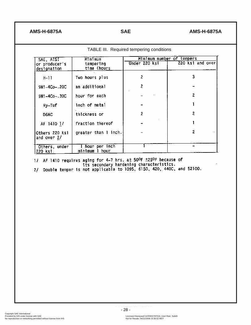
AMS-H-6875A SAE AMS-H-6875A
- 28 -
TABLE III. Required tempering conditions
Copyright SAE International Provided by IHS under license with SAE Licensee=Honeywell Int'l/5932787016, User=Nair, Subith
Not for Resale, 04/22/2008 23:36:02 MDTNo reproduction or networking permitted without license from IHS
--``,```,`,``,,,,`,,,,,``,,`,,``-`-`,,`,,`,`,,`---

AMS-H-6875A SAE AMS-H-6875A
- 29 -
FIGURE 1. Equivalent rounds for simple shapes
Copyright SAE International Provided by IHS under license with SAE Licensee=Honeywell Int'l/5932787016, User=Nair, Subith
Not for Resale, 04/22/2008 23:36:02 MDTNo reproduction or networking permitted without license from IHS
--``,```,`,``,,,,`,,,,,``,,`,,``-`-`,,`,,`,`,,`---


