Heat Transfer Analysis Of Medium Duty DI Diesel Engine Agarwal, Aniket Basu, Dr. M.R. Nandgaonkar:...
11
3627 www.ijifr.com Copyright © IJIFR 2015 Research Paper International Journal of Informative & Futuristic Research ISSN (Online): 2347-1697 Volume 2 Issue 10 June 2015 Abstract Now-a-days engines having smaller size & higher power ratings are in trend. Due to additional power deliverables required from smaller sizes, heat load on engine components have increased. Under this increased heat load, strength of component materials decreases drastically .When fatigue loadings act on these component with decreased strength, chances of engine failure increase. In order to avoid engine failure this heat load transfer inside engine needs to be understood very well .The major heat transfer that takes place inside engine is through engine cooling jacket. The work presented in this paper is numerically predicting the temperatures of engine components for a Direct Injection Medium Speed Heavy Duty Diesel Engine through CFD and validation of the simulated results with experimental results. The above objective is met by conducting in cylinder combustion simulation and then performing Conjugate Heat Transfer (CHT) analysis using boundary conditions obtained from combustion analysis for engine. Heat Transfer Analysis Of Medium Duty DI Diesel Engine Paper ID IJIFR/ V2/ E10/ 041 Page No. 3627-3637 Subject Area Mechanical Engineering Key Words Heat Transfer Analysis, Engine Water Jacket, Combustion Simulation, Conjugate Heat Transfer Received On 07-06-2015 Reviewed On 19-06-2015 Published On 20-06-2015 1. Deepali Agarwal Deputy Manager Corporate Research & Engineering Department, Kirloskar Oil Engines Limited, Pune 2. Aniket Basu Deputy Manager Corporate Research & Engineering Department, Kirloskar Oil Engines Limited, Pune 3. Dr. M.R. Nandgaonkar Associate Professor Department of Mechanical Engineering College Of Engineering, Pune
Transcript of Heat Transfer Analysis Of Medium Duty DI Diesel Engine Agarwal, Aniket Basu, Dr. M.R. Nandgaonkar:...

3627
www.ijifr.com Copyright © IJIFR 2015
Research Paper
International Journal of Informative & Futuristic Research ISSN (Online): 2347-1697
Volume 2 Issue 10 June 2015
Abstract
Now-a-days engines having smaller size & higher power ratings are in trend. Due to additional power deliverables required from smaller sizes, heat load on engine components have increased. Under this increased heat load, strength of component materials decreases drastically .When fatigue loadings act on these component with decreased strength, chances of engine failure increase. In order to avoid engine failure this heat load transfer inside engine needs to be understood very well .The major heat transfer that takes place inside engine is through engine cooling jacket. The work presented in this paper is numerically predicting the temperatures of engine components for a Direct Injection Medium Speed Heavy Duty Diesel Engine through CFD and validation of the simulated results with experimental results. The above objective is met by conducting in cylinder combustion simulation and then performing Conjugate Heat Transfer (CHT) analysis using boundary conditions obtained from combustion analysis for engine.
Heat Transfer Analysis Of Medium
Duty DI Diesel Engine Paper ID IJIFR/ V2/ E10/ 041 Page No. 3627-3637 Subject Area
Mechanical
Engineering
Key Words Heat Transfer Analysis, Engine Water Jacket, Combustion Simulation,
Conjugate Heat Transfer
Received On 07-06-2015 Reviewed On 19-06-2015 Published On 20-06-2015
1. Deepali Agarwal Deputy Manager Corporate Research & Engineering Department, Kirloskar Oil Engines Limited, Pune
2. Aniket Basu Deputy Manager Corporate Research & Engineering Department, Kirloskar Oil Engines Limited, Pune
3. Dr. M.R. Nandgaonkar Associate Professor Department of Mechanical Engineering College Of Engineering, Pune
3628
ISSN (Online): 2347-1697 International Journal of Informative & Futuristic Research (IJIFR)
Volume - 2, Issue - 10, June 2015 22ndEdition, Page No: 3627-3637
Deepali Agarwal, Aniket Basu, Dr. M.R. Nandgaonkar: Heat transfer analysis of medium duty DI Diesel Engine
1. Introduction
During the combustion process in internal combustion engines (ICE), a large amount of heat is
generated. This energy is absorbed by the cylinder walls, pistons, and cylinder head. A cooling
system is necessary in any internal combustion engine to effectively dispose off the heat generated.
Therefore, the function of the engine's cooling system is to remove excess heat from the engine and
to keep the engine up to correct temperature under all operating conditions. Therefore, the
management of heat transfer in an engine is critical to engine performance, efficiency and emission.
In the present study, conjugate heat transfer analysis is simulated for which the boundary conditions
are acquired from an in cylinder simulation. Then entire cooling jacket of a 6- cylinder medium duty
DI diesel engine is simulated for heat transfer through commercial CFD code star CCM+ and results
obtained are validated against experimental results which can further form the basis for cooling
jacket modification.
2. Methodology
The basic methodology adopted for numerically predicting the temperature of engine component for
a Direct Injection Medium Speed Heavy Duty Diesel Engine is in cylinder combustion followed by
Conjugate Heat Transfer Analysis. It can be defined as the ability to compute conduction of heat
through solids, coupled with convective heat transfer in fluid. Heat transfer through Convection can
be obtained as:
Similarly, Heat transfer through conduction
On solving these two simultaneous equations we can get Twall.The same idea is extended to 3-D i.e.
in x , y and z directions in our case.
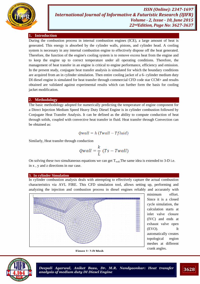
3. In cylinder Simulation
In cylinder combustion analysis deals with attempting to effectively capture the actual combustion
characteristics via AVL FIRE. This CFD simulation tool, allows setting up, performing and
analyzing the injection and combustion process in diesel engines reliably and accurately with
minimum effort.
Since it is a closed
cycle simulation, the
calculation starts at
inlet valve closure
(IVC) and ends at
exhaust valve open
(EVO). It
automatically creates
topological region
meshes at different
crank angles. Figure 1: 2-D Mesh

3629
ISSN (Online): 2347-1697 International Journal of Informative & Futuristic Research (IJIFR)
Volume - 2, Issue - 10, June 2015 22ndEdition, Page No: 3627-3637
Deepali Agarwal, Aniket Basu, Dr. M.R. Nandgaonkar: Heat transfer analysis of medium duty DI Diesel Engine
Combustion cavity considered is symmetric and the fuel mass flow is the same for all holes of the
injector, so only a segment of the cavity geometry for one injector hole is used. In 2D meshing basic
element size dependent cell size is considered, i.e. the basic cell size changes with respect to crank
angle. From crank angle to crank angle, also a 3D mesh is created based on the 2D meshing
parameters. 3D meshing parameters are important in injector region.
3.1 Inputs
Species transport, Combustion, Emissions and Spray models were selected. Whole simulation is
crank angle based, with numbers of time steps given based on crank angle. In initial conditions since
the calculation duration is from IVC, the pressures, temperature, turbulent kinetic energy, swirl and
direction of rotation axis at IVC is specified.
Standard WAVE mode for spray with blob injection where initial droplets have the diameter of the
nozzle orifice is used for the simulation, it often happens that there is hardly any fuel vapor close to
the nozzle. Modeling combustion in DI diesel engines requires taking into account the possibility to
burn under different regimes: premixed, non-premixed and partially premixed, due to the
inhomogeneous mixing of the reactants. Hence Extended Cohehrent Flame Model – 3 Zone (ECFM-
3Z) is used as the combustion model. The reaction mechanism to capture NOx formations can be
expressed in terms of the extended Zeldovich mechanism
3.2 Results
Figure 2 shows the comparison between experimental cylinder pressure (P-θ) diagrams with
simulated (P-θ) diagram at full load. This indicates that experimental and simulated result curves
follow similar trend. Computational and experimental results are in excellent agreement throughout
the compression, power and expansion strokes.
Figure 2: Experimental & Simulated Pressure Comparison
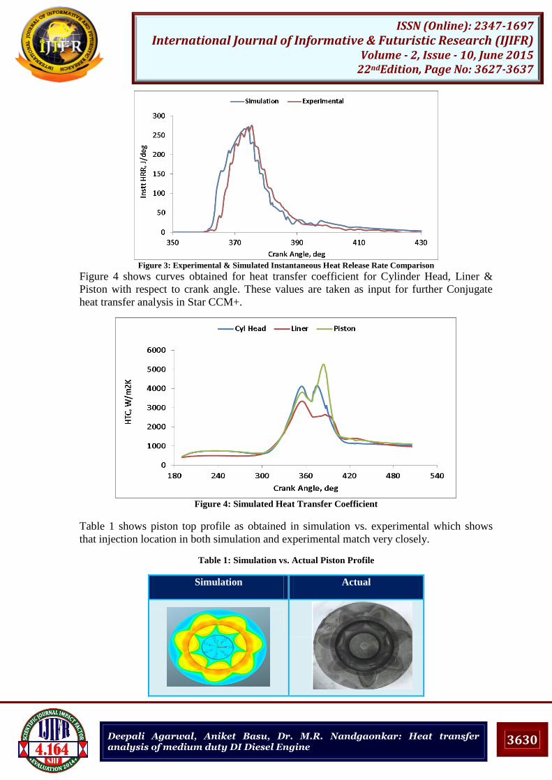
Figure 3 shows Heat release rate comparison between experimental and simulated values both
curves follow similar trend.
3630
ISSN (Online): 2347-1697 International Journal of Informative & Futuristic Research (IJIFR)
Volume - 2, Issue - 10, June 2015 22ndEdition, Page No: 3627-3637
Deepali Agarwal, Aniket Basu, Dr. M.R. Nandgaonkar: Heat transfer analysis of medium duty DI Diesel Engine
Figure 3: Experimental & Simulated Instantaneous Heat Release Rate Comparison
Figure 4 shows curves obtained for heat transfer coefficient for Cylinder Head, Liner &
Piston with respect to crank angle. These values are taken as input for further Conjugate
heat transfer analysis in Star CCM+.
Figure 4: Simulated Heat Transfer Coefficient
Table 1 shows piston top profile as obtained in simulation vs. experimental which shows
that injection location in both simulation and experimental match very closely.
Table 1: Simulation vs. Actual Piston Profile
Simulation Actual

3631
ISSN (Online): 2347-1697 International Journal of Informative & Futuristic Research (IJIFR)
Volume - 2, Issue - 10, June 2015 22ndEdition, Page No: 3627-3637
Deepali Agarwal, Aniket Basu, Dr. M.R. Nandgaonkar: Heat transfer analysis of medium duty DI Diesel Engine
4. CFD Analysis And Model Setup
In this study, CFD analysis of the existent coolant passage model will be conducted to determine the
critical locations within engine block and head. 3-D CAD (Computer Aided Design) model of the
engine block coolant jacket, the cylinder head coolant jacket, was developed in house. Commercially
available software package Star CCM+ by CD Adapco Group has been utilized for CFD analysis.
Same software was used for cleaning up and meshing purposes and for pre-processing, processing
and post processing steps.
4.1Assumptions for Numerical Simulation
The coolant flow in coolant cavities of a cylinder head was assumed to be 3D steady state,
Incompressible turbulent flow, viscosity in the near wall region was taken into account. Turbulence
model selection made on basis of type of system selected, type of grid used and type of physics
expected in that domain. After referring available help files of STAR-CCM+ and referring to CFD
literature it was decided to choose realizable k-ε model for the present study. There were second
option of SST k-ω mentor model which also stand acceptable for present physics but it strictly
requires very refine mesh around boundaries which will result into y+ within 0 to 1. This was not
possible in present case due to y+ varying all over.
Three dimensional, Steady, Liquid, Segregated flow, Constant density, Turbulent, Reynolds average
Navier-Strokes, K-epsilon turbulence, Realizable K-epsilon two layer, Two layer all y+ wall
treatment, Segregated fluid temperatures and Segregated solid energy solvers are used for fluid
region.
Table 2: 1Assumptions for Numerical Simulation
Solid Boundary Conditions Temperature Heat Transfer Coefficient
Deck Face 1200 625
Exhaust Port 1000 580
Inlet Port 313 100
Exhaust Valve Guide 313 160
Inlet Valve Guide 313 100
Exhaust Valve Seat 1100 600
Inlet Valve Seat 313 600
Solid Head 313 100
Liner Top 650 1360
Liner Middle 540 670
Liner Bottom 460 520
4.2 Simulation Results
The pressure loss as shown in fig 5 between the inlet and outlet is calculated to be as 0.21 bar which
is a good indicator of low resistance in flow and potential. Water pump will have to deliver more
than the pressure loss across the cooling jacket i.e. 0.21 bar in order to force the coolant inside the
circuit and keep it circulating with sufficient velocity.

3632
ISSN (Online): 2347-1697 International Journal of Informative & Futuristic Research (IJIFR)
Volume - 2, Issue - 10, June 2015 22ndEdition, Page No: 3627-3637
Deepali Agarwal, Aniket Basu, Dr. M.R. Nandgaonkar: Heat transfer analysis of medium duty DI Diesel Engine
Figure 5: Pressure Contour
Figure 6: Fluid Streamlines
In the figure 6, Fluid flow streamlines are shown which show less flow going to cylinders as
a result of which it will suffer high temperature regions.
Figure 7: Cylinder Head Temperature Contour

3633
ISSN (Online): 2347-1697 International Journal of Informative & Futuristic Research (IJIFR)
Volume - 2, Issue - 10, June 2015 22ndEdition, Page No: 3627-3637
Deepali Agarwal, Aniket Basu, Dr. M.R. Nandgaonkar: Heat transfer analysis of medium duty DI Diesel Engine
Figure 8: Deck Face Temperature
Figure 7 and 8 clearly shows the maximum temperature is found in the region of exhaust port and
the region near the exhaust bridge on the deck face. Thus more attention is given for the pressure and
velocity contours of the cooling jacket as there is the possibility of nucleate boiling of coolant within
this region. Boiling causes a thin film of coolant vapour to form between the fluid flow and the solid,
which acts as an insulator and reduces the heat transfer coefficient.
Figure 9: Velocity Contour in Engine Block
Figure 10: Liner Temperature
Hot Spots

3634
ISSN (Online): 2347-1697 International Journal of Informative & Futuristic Research (IJIFR)
Volume - 2, Issue - 10, June 2015 22ndEdition, Page No: 3627-3637
Deepali Agarwal, Aniket Basu, Dr. M.R. Nandgaonkar: Heat transfer analysis of medium duty DI Diesel Engine
The analysis of thermal fields of cylinder liner has crucial importance because it provides an insight
into several very important phenomenon’s that are associated with the thermal stresses, strains and
with the heat fluxes exchanged. The dotted circles in Figure 9 show that the flow velocity in this
region is relatively lesser than the other cylinders thereby indicating the possibility of stagnation.
Hence, the heat carried away by the coolant in this region will be reduced. This in turn is a potential
location of hot spot creation visible in Figure 10. It shows how the temperature varies along the
length of the liner. The lower region of liner is only exposed to combustion products for part of cycle
after significant gas expansion has occurred, the temperature decreases significantly.
5. Experimental Validation
By focusing on literature survey and CFD analysis done on the engine we finalize the maximum
temperature location in the cylinder head. Along with the bottom of cylinder head the exhaust port is
also exposed to elevated temperatures thus to predict the surface temperature in the exhaust port it is
necessary to install the templug at the exhaust port.
Table 3: Simulation Results
Location Experimental Simulation Error %
1 263 deg C 282 deg C 7.2
2 340 deg C 316 deg C 7.0
3 252 deg C 238 deg C 5.5
4 195 deg C 219 deg C 12.3
5 178 deg C 195 deg C 9.5
4 5
Figure 11: Experimental templug location

3635
ISSN (Online): 2347-1697 International Journal of Informative & Futuristic Research (IJIFR)
Volume - 2, Issue - 10, June 2015 22ndEdition, Page No: 3627-3637
Deepali Agarwal, Aniket Basu, Dr. M.R. Nandgaonkar: Heat transfer analysis of medium duty DI Diesel Engine
6. Design Improvement
We have witnessed in the simulation results that the temperature of the solids rise at stagnation areas
because of ineffective cooling. Following are the modifications which have been incorporated for
minimizing stagnation region with least pressure drop:
a) Increase in coolant flow rate
b) Varying the diameter of transfer holes
c) New water jacket design
6.1 Increased Coolant Flow Rate
With increased flow rate of the pump, the pressure drop across the circuit is 0.69 bar as against 0.22
with lower flow rate, thus increasing pressure drop by 32 % which is not acceptable.
6.2Varying Diameter of Transfer Holes
On reviewing mass flow distributions for original and modified holes unequal distribution in
cylinders still exists. Therefore, this modification will also not improve stagnation areas.
6.3 New Water Jacket Design
The highlighting features of the new jacket design are the rails through which the coolant passes into
the crankcase jacket. The rails implemented have wavy pattern and constantly decreasing cross
section. The wavy pattern and constantly decreasing cross section area ensures that the flow velocity
does not decrease thereby reducing stagnation.
Due to this modification in rails, the old oil cooler shape was not able to fit in this improved model.
We could see it fouling with the core and hence the alternative approach was too introduced.
Therefore an orifice that would give the same pressure drop as the oil cooler has been given.
Figure 12 shows velocity contours for modified design. Stagnation regions are not present in
modified jacket as evident from this figure. Equal distribution of flow can be seen.
Figure 12: Velocity Contour
Streamlines shows good velocity in all cylinders. Since the stagnation observed is less, the chances
of hotspots are also relatively less. Hence this design gives improvement in terms of pressure drop
and temperature hotspots.

3636
ISSN (Online): 2347-1697 International Journal of Informative & Futuristic Research (IJIFR)
Volume - 2, Issue - 10, June 2015 22ndEdition, Page No: 3627-3637
Deepali Agarwal, Aniket Basu, Dr. M.R. Nandgaonkar: Heat transfer analysis of medium duty DI Diesel Engine
7. Conclusion
In cylinder simulation results follow similar trend as that of experimental results and all
results match with experimental within 6-10%.This validates our boundary conditions used
for conjugate heat transfer analysis.
The locations at which fuel is injected on piston match exactly with actual locations as
shown by results.
The models for conjugate heat transfer analysis is also validated against experimental results
within 10% error which validates process used for Conjugate Heat transfer. Thus current
procedure can also be used for conjugate heat transfer analysis for any modification done on
water jacket.
Modification 1 shows that by increasing pump flow rate pressure drop across water jacket
increases by 32% which is not acceptable.
Modification 2 shows that flow rate through transfer holes increases in same amount as size
of holes is increased.
Modification-3 shows 16% less pressure drop across jacket as compared to actual model
.Also stagnation regions are removed . Therefore it is recommended.
Boundary conditions obtained from both conjugate heat transfer analysis and in cylinder
simulation can be mapped to engine cylinder assembly as part of coupled approach with
Computational Fluid Dynamics and Finite Element modelling .This approach introduces
many advanced features.
8. Abbreviations and Acronyms
FE Finite Element
CFD Computational Fluid Dynamics
CHT Conjugate Heat Transfer
CAE Computer Aided Engineering
Ts Surface Temperature
Twall Wall Temperature
H Heat Transfer Coefficient
Tfluid Fluid Temperature
qwall Wall heat transfer
L Length
K Thermal Conductivity
Nu Nusselt Number
Re Reynolds Number
B Cylinder Bore
W Local Average Gas Velocity
Sp Mean Piston Velocity
Pr Refernce Pressure
Tr Reference Temperature
Pm Motored Pressure
Vd Displacement Volume
TDC Top Dead Center

3637
ISSN (Online): 2347-1697 International Journal of Informative & Futuristic Research (IJIFR)
Volume - 2, Issue - 10, June 2015 22ndEdition, Page No: 3627-3637
Deepali Agarwal, Aniket Basu, Dr. M.R. Nandgaonkar: Heat transfer analysis of medium duty DI Diesel Engine
7. References [1] Helgi Fridriksson,Bengt Sunden.”CFD investigation of heat transfer in a diesel engine with diesel and PPC
combustion models” SAE Technical paper no.2011-01-1838.
[2] Aditya Mulemane,Ravindra Soman.”CFD based complete engine cooling jacket development and analysis ”SAE
Technical Paper no. 2007-01-4129
[3] Jukka Tiainen,Ilari Kallio.”Heat Transfer Study of a High Power Density Diesel Engine” SAE Technical Paper
no. 2004-01-2962
[4] R.Tatschi,B. Basara.”Advanced Turbulent Heat Transfer Modeling for IC –Engine Applications Using AVL
FIRE “International Multidimensional Engine Modeling User’s Group Meeting (2006).
[5] O.Iqbal,S. Jonnalagedda.” Comparison of 1-D vs. 3-D combustion boundary conditions for SI engine”
[6] Michael Vincent Jensen.” Heat Transfer in Large Two-Stroke Marine Diesel Engines” Doctoral Thesis,
Technical University of Denmark,(2012).
[7] Hazrat M. A.,Masjuki H. H.,” Steady State Analysis of Coolant Temperature Distribution in a Spark Ignition
Engine Cooling Jacket” International Journal of Mechanical and Materials Engineering (IJMME), Vol. 7 (2012),
No. 3, 243-250
[8] Carlos Adolfo Finol Parra, “Heat Transfer Investigations in a Modern Diesel Engine” Acta Polytechnica Vol. 43
No. 5/2003 (1998)
[9] Xin Jun,Shih Stephen," Integration of 3D Combustion Simulations and Conjugate Heat Transfer Analysis to
Quantitatively Evaluate Component Temperatures "SAE Technical Paper 2003-01-3128
[10] Fontanesi S.,Carpentiero D.,” A New Decoupled CFD and FEM Methodology for the Fatigue Strength
Assessment of an Engine Head” SAE Technical Paper 2008-01-0972
[11] Fontanesi S.,McAssey E. V. “Experimental and Numerical Investigation of Conjugate Heat Transfer in a HSDI
Diesel Engine Water Cooling Jacket” SAE Technical Paper 2009-01-0703
[12] Londhe Abhijit,Yadav Vivek “A Multi-disciplinary Approach for Evaluating Strength of Engine Cylinder
Head and Crankcase Assembly under Thermo-Structural Loads” SAE Technical Paper 2009-01-0819.
[13] Veress Arpad,Nemeth Huba “ Numerical Analysis and Semi-Optimisation on Water Jacket for Reciprocating
Compressors” Knorr-Bremse R&D Center, Budapest.
[14] John B Heywood, “Thermal loading and temperature measurement in diesel engine component “Fundamentals
of I.C engines (1988).
[15] Tutorials on CFD by “CD Adapco‟.
[16] http://www.cd-adapco.com/stephen-ferguson/natures-answer-meshing.
[17] Malashekara and Versteeg “An Introduction to Computational Fluid dynamics”, Cambridge Publications.
[18] Nader Raeie, Sajjad Emami, Omid Karimi Sadaghiyani “Effects of injection timing, before and after top dead
centre on the propulsion and power in a diesel engine”, Propulsion and Power Research2014;3(2):59–67
[19] “The chemistry of Diesel engine”, www.chembloggreen1.wordpress.com.
[20] Taylor C.F., “Internal combustion engine in theory and practice”volume 2 MIT Press, London, 1968.
[21] Ganesan V,”Internal Combustion engines “, Third edition McGraw-Hill 2008
[22] B.V.V.S.U. Prasad, C.S. Sharma, T.N.C. Anand, R.V. Ravikrishna , High swirl-inducing piston bowls in small
diesel engines for emission reduction , Applied Energy 88 (2011)
[23] Christoph Garth, Robert S. Laramee, Xavier Tricoche, Jurgen Schneider, and Hans Hagen, Extraction and
Visualization of Swirl and Tumble Motion from Engine Simulation Data.
[24] Naber, J.D. and Reitz, R.D. “Modeling Engine Spray/Wall Impingement” S E-880107
[25] Alkidas, A.C., 1986. "On the Premixed Combustion in a Direct-Injection Diesel Engine", ASME Paper 86-ICF-
4
[26] United states environmental protection agency, Alternative Control Techniques Documents -- NOx Emissions
From stationary Reciprocating internal combustion engines,(1993).
Biographies
1st Deepali Agarwal , working as Deputy Manager CRE in Kirloskar Oil Engines Ltd, Pune .She is also
pursuing M.Tech Thermal Engineering From College of Engineering ,Pune.
2nd Aniket Basu ,working as Deputy Manager CRE in Kirloskar Oil Engines Ltd, Pune .His working areas
and interests include Computational Fluid Dynamics Simulation, Combustion Hardware Optimization
& Common Rail Calibration .
3rd Dr. M.R. Nandgaonkar, working as Associate Professor, in Mechanical Engineering Dept. of College
of Engineering, Pune. He completed his PhD. (IC Engines) from Amravati University in 2002. His
Area of interest includes I C Engine, Alternative Fuels & CFD. He has 21 years of Teaching
Experience along with 10 years Research experience. He has 50 publications in National &
International Journals & conferences.

![aniket[1] (1) (2)](https://static.fdocuments.net/doc/165x107/589997681a28ab30328b75f3/aniket1-1-2.jpg)