![Finite element modeling of pipe-laying dynamics using ... · ulations, such as Offpipe [1], Pipe-Lay [2], and OrcaFlex [3]. Each of these software packages has its advantages as well](https://static.fdocuments.net/doc/165x107/60d465079ba3671927256226/finite-element-modeling-of-pipe-laying-dynamics-using-ulations-such-as-offpipe.jpg)
Heat traced pipe-in-pipe for S or J-lay proof of concept...
15
MCE Deepwater Development 2016 PAU, FRANCE • 5-7 APRIL 2016 Heat traced pipe-in-pipe for S or J-lay – proof of concept test results C. T’Joen (Shell), Y. Cadoret (Deutsch), M. Nikles (Omnisens), E. Perez and C. Geertsen (ITP InTerPipe)
Transcript of Heat traced pipe-in-pipe for S or J-lay proof of concept...

MCE Deepwater Development 2016
PAU, FRANCE • 5-7 APRIL 2016
Heat traced pipe-in-pipe for S or J-lay –
proof of concept test results
C. T’Joen (Shell), Y. Cadoret (Deutsch), M. Nikles (Omnisens), E. Perez and C.
Geertsen (ITP InTerPipe)
MCE Deepwater Development 2016
Overview
• Introduction
• Electrical heat tracing / EHTF Technology (ITP Interpipe)
• Prototype + flowloop test results
• Conclusions and outlook
2

MCE Deepwater Development 2016
Introduction
• Increasingly difficult oil and gas discoveries are considered for development
• Economics drive long distance tie-backs
• Hydrate management issues
3
Solution: Electrically Heat Traced Flowlines (EHTF)

MCE Deepwater Development 2016
Electrical heat tracing
• Temperature management using electrical heating is not new:• Direct electrical heating (DEH) developed since the 1990s and installed on 14 pipelines (110 km).
• high power requirement, typically limited to maximum 50 km for 18” pipe
• Alternative: electrical heat tracing for Pipe-in-Pipe• Based on existing highly insulated PiP technology
• Resistance wires added on the inner pipe
• Power Consumption: 5 – 15 kW/km (5-20 times lower than DEH)
• Range: 20 – 50 km/kV, much lower than DEH
• EHTF concept (ITP Interpipe) for S-lay• Individually heat-traced segments in set in parallel
• Three phase AC power connections by Deutsch (qualified for Ormen Lange)
4
Insulation coating Heating wires
Inner pipeOuter pipe
MCE Deepwater Development 2016
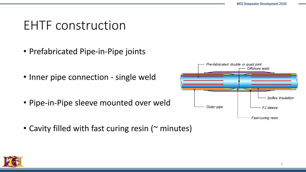
EHTF construction
• Prefabricated Pipe-in-Pipe joints
• Inner pipe connection - single weld
• Pipe-in-Pipe sleeve mounted over weld
• Cavity filled with fast curing resin (~ minutes)
5
MCE Deepwater Development 2016
Proof of concept testing - objectives
• Operating experience with the Deutsch connector and DTS monitoring with OMNISENS fibre optic
• Measuring U-value of the fully installed system (including the sleeves)
• Test operation in heated mode – temperature maintenance / control
• Assess the impact of an electrical connector failure – can we still operate?
6
MCE Deepwater Development 2016
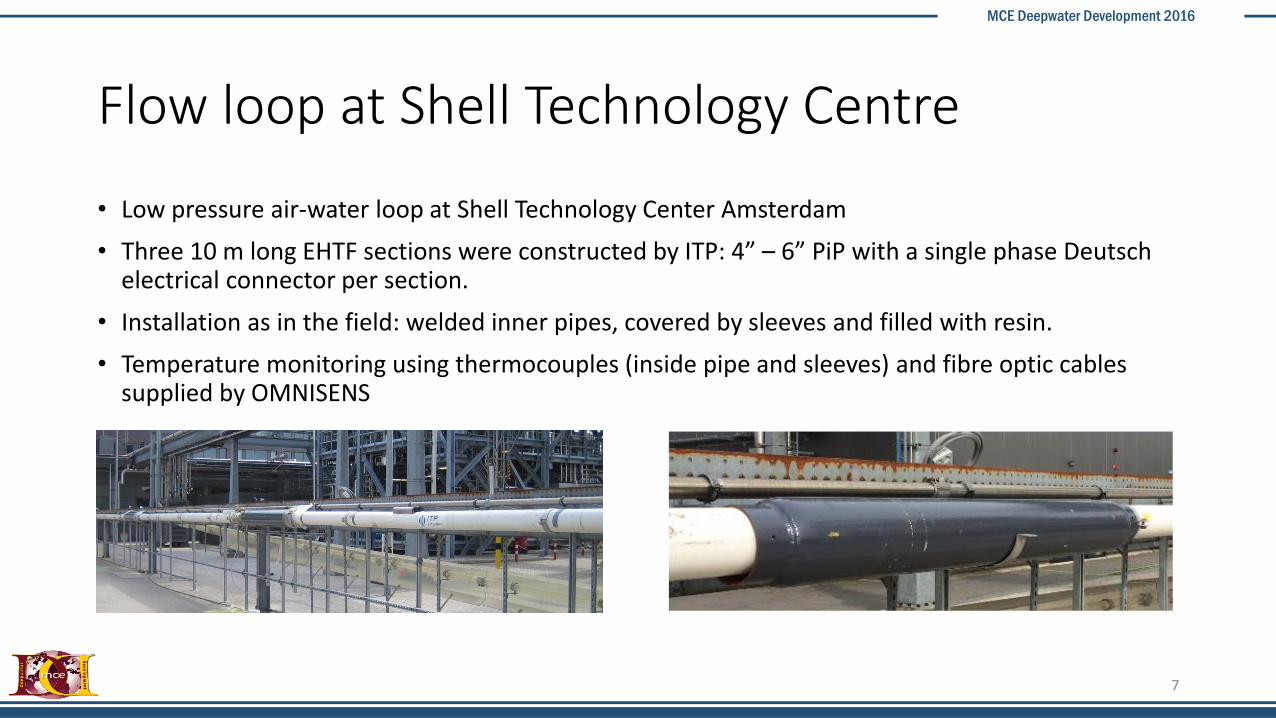
Flow loop at Shell Technology Centre
• Low pressure air-water loop at Shell Technology Center Amsterdam
• Three 10 m long EHTF sections were constructed by ITP: 4” – 6” PiP with a single phase Deutsch electrical connector per section.
• Installation as in the field: welded inner pipes, covered by sleeves and filled with resin.
• Temperature monitoring using thermocouples (inside pipe and sleeves) and fibre optic cables supplied by OMNISENS
7

MCE Deepwater Development 2016
Experimental setup / operation
• Guard heaters mounted on each side to compensate heat losses at the ends
• Temperature measurements using thermocouples and fiber optic cable (internal and external)
• Power supplied through the loop control unit (220 V)
• Tests during shut-in conditions – no flow, pipes filled with water, air or a mixture.
• Temperature control using a TIC unit as programmed in the control system (on/off switch)
8
MCE Deepwater Development 2016
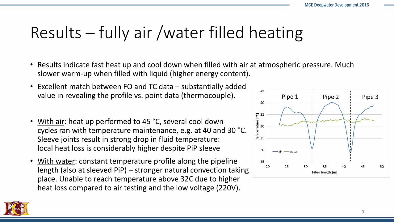
Results – fully air /water filled heating
• Results indicate fast heat up and cool down when filled with air at atmospheric pressure. Much slower warm-up when filled with liquid (higher energy content).
• Excellent match between FO and TC data – substantially added value in revealing the profile vs. point data (thermocouple).
• With air: heat up performed to 45 °C, several cool down cycles ran with temperature maintenance, e.g. at 40 and 30 °C.Sleeve joints result in strong drop in fluid temperature:local heat loss is considerably higher despite PiP sleeve
• With water: constant temperature profile along the pipelinelength (also at sleeved PiP) – stronger natural convection takingplace. Unable to reach temperature above 32C due to higher heat loss compared to air testing and the low voltage (220V).
9
Pipe 1 Pipe 2 Pipe 3
MCE Deepwater Development 2016
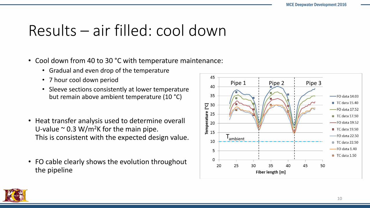
Results – air filled: cool down
• Cool down from 40 to 30 °C with temperature maintenance:• Gradual and even drop of the temperature
• 7 hour cool down period
• Sleeve sections consistently at lower temperaturebut remain above ambient temperature (10 °C)
• Heat transfer analysis used to determine overall U-value ~ 0.3 W/m2K for the main pipe. This is consistent with the expected design value.
• FO cable clearly shows the evolution throughoutthe pipeline
10
Tambient
Pipe 1 Pipe 2 Pipe 3

MCE Deepwater Development 2016
Results – water filled: cool down
• Long cool down time due to the high heat capacity: more than 70 hours
• Two cool down cycles performed
• Flat temperature profile during cool downgradually moving closer to the ambient temperature
• Estimated U value: 0.55 W/(m2.K)
11
MCE Deepwater Development 2016
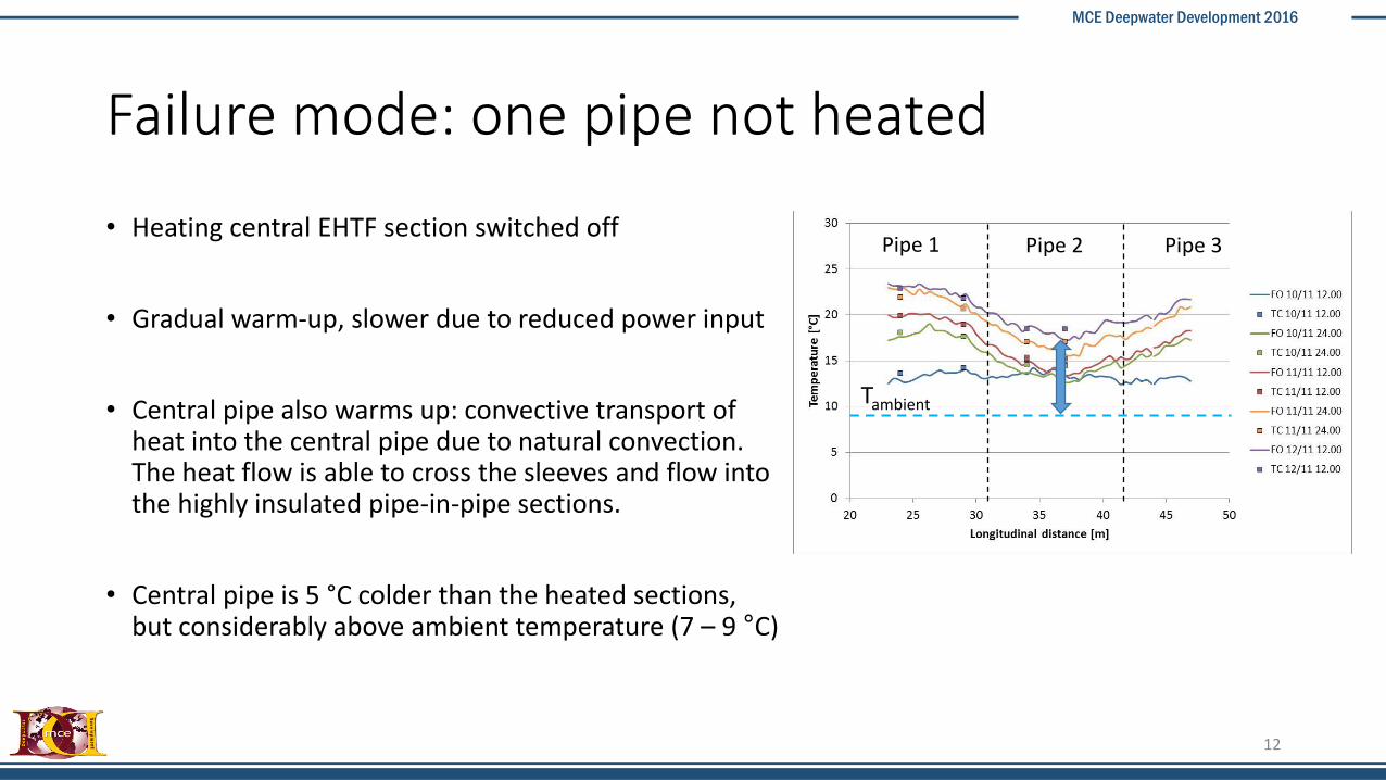
Failure mode: one pipe not heated
• Heating central EHTF section switched off
• Gradual warm-up, slower due to reduced power input
• Central pipe also warms up: convective transport of heat into the central pipe due to natural convection.The heat flow is able to cross the sleeves and flow intothe highly insulated pipe-in-pipe sections.
• Central pipe is 5 °C colder than the heated sections, but considerably above ambient temperature (7 – 9 °C)
12
Tambient
Pipe 1 Pipe 2 Pipe 3

MCE Deepwater Development 2016
Inclined experiment – 2 degrees
• Fully liquid filled: temperature gradient appears (top warmer)
• Half liquid filled + degraded mode: no natural convection in the gas filled section, so it cools down to ambient temperature in 48 hours
13
Tambient
Pipe 1 Pipe 2 Pipe 3 Pipe 1 Pipe 2 Pipe 3

MCE Deepwater Development 2016
Measured overall U values
• Fully air filled system: 0.3 W/(m2.K) Fully water filled system: 0.55 W/(m2.K)
• With air: no convection (low sleeve temperature), so U value ~ U value individual PiP section
• With water: natural convection: so U value ~ U value of the assembly
• Knowing the field joint length (~ 2 m) results in estimate for its U value: 1.55 W/(m2.K)
• Considering then a field joint length of 48 m (as installed offshore) gives an overall U value of 0.35 W/(m2.K) for the entire assembly
14

MCE Deepwater Development 2016
Conclusions
• Proof of concept achieved through flowloop testing – Technology Readiness Level 5 (API): basic technological components integrated and tested in a simulated environment
• Total installed U-value of 0.35 W/m2.K when using quad joints
• Uniform temperature profile in liquid filled sections – cold spots at the sleeves for gas, though well above ambient temperature
• Unheated section kept warm by neighbouring sections if sufficient liquid is present, high pressure gas may also be effective.
• Fibre optic system (DTS) visualized the temperature profile with good accuracy
15