Heat Insulation
4
si Heat Insulation J. L. FINCK The J. L. Finck Laboratories, New York, N. Y. HE purpose of this paper is to consider some aspects of heat insulation as viewed from the granular structure of materials and also from the standpoint of large structures. T Fibrous Materials In the case of solid metals the thermal conductivities may range from about 3000 down to approximately 250 B. t. u. per hour per square foot per O F. per inch. For solid nonmetallic materials, such as brick, glass, stone, etc., the range may be from about 20 to 3, and for woods, from about 1 to 0.5, in the same units. The heat transfer through such materials is by conduction only. If such materials are shredded, the resultant structure will be in an entirely different class from an insulation standpoint. For example, the conductivity of steel is about 300, and this is reduced to 0.5 for steel wool. The conductivity of limestone rock or glass ranges from 5 to 15 but is.reduced to 0.3 for the wool of these materials. The bulk density is greatly reduced in the shredding process, and there is a general relation be- tween density and conductivity for a given fibrous material. However, when material is shredded, a gas, usually air, is actually added to the bulk, and the presence of the air ac- counts for the reduced heat conduction. The conductivity of gases may vary from about 1 for hydrogen down to approxi- mately 0.05 for chlorine. For air the conductivity is 0.15. Should the air contained in the shredded mass be replaced by, say, carbon dioxide whose conductivity is 0.09, an appreciable reduction in the over-all conductivity will be obtained. In some cases this principle is utilized to advantage-for exam- ple, in the making of expanded rubber-where the cells are filled with a gas other than air. Convection of heat within a fibrous mass is usually negli- gible. The reason is that there is a film of air which adheres to each fiber, and fibers are usually packed close enough to cause the air film of one fiber to touch that of the adjacent fibers. This applies only to natural convection and not to forced convection through the fibrous mass. If the bulk density is sufficiently low, radiation will pene- trate through the mass. The writer showed this effect by means of dusting fibers with powdered aluminum, with a re- sultant reduction in conductivity (1). However, as the den- sity increases, the radiation becomes absorbed by the fibers, and beyond a certain density, radiation is negligible. We find, therefore, that for each grade of fibrous material a certain optimum density exists. For densities greater and less than this optimum density, the conductivity will increase. Figure 1 gives curves for the variation of conductivity with density for a few fibrous materials; in each case an optimum density is observed (1). In considering the heat flow through a fibrous mass, the boundaries between the fibers and the surrounding air must be considered. Even though the conduction along the fibers may be large, the thermal resistances offered by the air films reduce the over-all conduction considerably. What, then, happens when moisture penetrates the fibrous mass? If this moisture is absorbed by the fibers, leaving the surfaces of the fibers dry, the effect on the over-all conduction will be slight. However, if enough moisture is added so that the surfaces of the fibers are wet, the contacts between the adjacent fibers are fused by the water, and the previous high-thermal-resistance air contacts are replaced by low-resistance water contacts. The over-all conduction is greatly increased. Other ma- terials, such as oil, rosin, asphalt, cement, etc., will have the same effect as water. This is a very practical problem; for example, in the industry we find some rock wools which are treated with an oil or paraffin for moisture proofing. In the The mechanism of heat flow in fibrous materials is considered and is applied to a few cases in the manufacture of heat- insulating materials. The heat insulation of large structures (walls and air spaces) is also considered and the part which con- duction, convection, and radiation play in the heat transfer is discussed. Insulation by reflective insulation is considered in some detail. A few practical insulation problems are discussed. making of rigid or semirigid fibrous boards, the fibers may be coated with a resinous or asphaltic material. In all such cases, some of the insulating value of the product must be sacrificed. The arrangement of the fibers within a board will also affect its conductivity (1) since fibers which lie parallel to the line of heat flow offer more direct paths of heat conduction with fewer contact resistances, and vice versa. From an industrial and economic standpoint it is interesting to consider the effect of the mixing of different grades of fibers on the resultant conductivity. For example, the conduc- tivity of flax fibers is about 0.27, while that of wood shavings may be as high as 0.40. If they are mixed in the proportion by weight of 1 part of flax to 5 parts of wood shavings, the resultant conductivity will be about 0.33; in other words, the conductivity of the mixture will be closer to the value of flax than would be expected by its proportion in the mixture. This principle makes it possible to use a small proportion of a fiber material which may be comparatively expensive, to 824
Transcript of Heat Insulation

si Heat Insulation J. L. FINCK The J. L. Finck Laboratories, New York, N. Y.
HE purpose of this paper is to consider some aspects of heat insulation as viewed from the granular structure of materials and also from the standpoint of large structures. T
Fibrous Materials
In the case of solid metals the thermal conductivities may range from about 3000 down to approximately 250 B. t. u. per hour per square foot per O F. per inch. For solid nonmetallic materials, such as brick, glass, stone, etc., the range may be from about 20 to 3, and for woods, from about 1 to 0.5, in the same units. The heat transfer through such materials is by conduction only.
If such materials are shredded, the resultant structure will be in an entirely different class from an insulation standpoint. For example, the conductivity of steel is about 300, and this is reduced to 0.5 for steel wool. The conductivity of limestone rock or glass ranges from 5 to 15 but is.reduced to 0.3 for the wool of these materials. The bulk density is greatly reduced in the shredding process, and there is a general relation be- tween density and conductivity for a given fibrous material. However, when material is shredded, a gas, usually air, is actually added to the bulk, and the presence of the air ac- counts for the reduced heat conduction. The conductivity of gases may vary from about 1 for hydrogen down to approxi- mately 0.05 for chlorine. For air the conductivity is 0.15. Should the air contained in the shredded mass be replaced by, say, carbon dioxide whose conductivity is 0.09, an appreciable reduction in the over-all conductivity will be obtained. In some cases this principle is utilized to advantage-for exam- ple, in the making of expanded rubber-where the cells are filled with a gas other than air.
Convection of heat within a fibrous mass is usually negli- gible. The reason is that there is a film of air which adheres to each fiber, and fibers are usually packed close enough to cause the air film of one fiber to touch that of the adjacent fibers. This applies only to natural convection and not to forced convection through the fibrous mass.
If the bulk density is sufficiently low, radiation will pene- trate through the mass. The writer showed this effect by means of dusting fibers with powdered aluminum, with a re- sultant reduction in conductivity (1). However, as the den- sity increases, the radiation becomes absorbed by the fibers, and beyond a certain density, radiation is negligible. We find, therefore, that for each grade of fibrous material a certain optimum density exists. For densities greater and less than this optimum density, the conductivity will increase. Figure 1 gives curves for the variation of conductivity with density for a few fibrous materials; in each case an optimum density is observed (1).
In considering the heat flow through a fibrous mass, the boundaries between the fibers and the surrounding air must
be considered. Even though the conduction along the fibers may be large, the thermal resistances offered by the air films reduce the over-all conduction considerably. What, then, happens when moisture penetrates the fibrous mass? If this moisture is absorbed by the fibers, leaving the surfaces of the fibers dry, the effect on the over-all conduction will be slight. However, if enough moisture is added so that the surfaces of the fibers are wet, the contacts between the adjacent fibers are fused by the water, and the previous high-thermal-resistance air contacts are replaced by low-resistance water contacts. The over-all conduction is greatly increased. Other ma- terials, such as oil, rosin, asphalt, cement, etc., will have the same effect as water. This is a very practical problem; for example, in the industry we find some rock wools which are treated with an oil or paraffin for moisture proofing. In the
The mechanism of heat flow in fibrous materials is considered and is applied to a few cases in the manufacture of heat- insulating materials. The heat insulation of large structures (walls and air spaces) is also considered and the part which con- duction, convection, and radiation play in the heat transfer is discussed. Insulation by reflective insulation is considered in some detail. A few practical insulation problems are discussed.
making of rigid or semirigid fibrous boards, the fibers may be coated with a resinous or asphaltic material. I n all such cases, some of the insulating value of the product must be sacrificed. The arrangement of the fibers within a board will also affect its conductivity (1) since fibers which lie parallel to the line of heat flow offer more direct paths of heat conduction with fewer contact resistances, and vice versa.
From an industrial and economic standpoint it is interesting to consider the effect of the mixing of different grades of fibers on the resultant conductivity. For example, the conduc- tivity of flax fibers is about 0.27, while that of wood shavings may be as high as 0.40. If they are mixed in the proportion by weight of 1 part of flax to 5 parts of wood shavings, the resultant conductivity will be about 0.33; in other words, the conductivity of the mixture will be closer to the value of flax than would be expected by its proportion in the mixture. This principle makes it possible to use a small proportion of a fiber material which may be comparatively expensive, to
824

JULY, 1939 INDUSTRIAL AND ENGINEERING CHEMISTRY 825
0. I I I I I I I I 1
reduce the conductivity of a cheap but poor insulator. Many of the farm products which are more or less waste at present, such as cornstalks, wheat straw, bagasse, etc., repre- sent a great source of supply of raw fibers for the manufacture of heat-insulating materials, and with suitable admixtures, very satisfactory products could be developed.
Characteristics of Wall Structures
Turning now to large structures, we find that the particular arrangement of materials within a wall has a great deal to do with its heat-insulating properties.
Consider first the simple case of the surface of a wall. Heat will be transferred by radiation to this surface from all surrounding objects. Heat will also be transferred to this surface by conduction and convection of the ambient air. Just as in the case of the fibrous materials, a film of air adheres to the solid surface. Although increased convection of the ambient air will reduce the thickness of this film, there is always a thin layer through which no heat is transferred by convection but only by conduction and radiation.
In calculating the heat flow from a solid surface to the sur- rounding ambient air, i t is convenient to combine all three modes of transfer and write the equation as
A q = f G l
where q = heat transferred per unit time through area A t1, Q = temperatures of surface and ambient air, respectively
The constant f is called the "surface conductance", and l/f is the "surface resistance." Figure 2 gives values for surface resistances, as determined during experiments on the heat transfer through building walls (4). These were vertical surfaces made of ordinary building materials whose emissivi- ties were 90 per cent or more. Assume a mean temperature for the surface and ambient air of 50" F. From Figure 2 we have for the surface resistance 0.47" F. for a heat flow of 1 B. t. u. per hour per square foot. I n calculating the total thermal resistance of a wall structure, we would have to in- clude the surface resistance. Suppose the structure consists simply of a thin sheet of paper, iron, or glass. Even though the material itself offers very little thermal resistance, we still have two surface resistances in this case, and the total resist- ance for 50" F. mean would be 2 X 0.47 or 0.94.
The ratio of heat transferred by radiation to that by con- duction and convection from a vertical surface may be calcu- lated as follows : For black-body radiation from surrounding space a t temperature T1 to the wall a t temperature Tz, we have from the Stefan-Boltzmann law:
R = u(T1' - Tz') = 4~ X AT X Ta,,. (approximately) (2)
where R = radiation per unit time per unit area
u = Stefan-Boltzmann constant
AT = Ti - Tz 7's". = '/z(Ti + Tz)
If the surface is not perfectly black but has an emissivity, e, we may write:
R = 4eu X AT X Tan,. (3)
I n British units, u = 1.72 X 1O-O B. t. u. per hour per square foot. Consider a mean temperature of 50" F., and Tav. = 460 + 50 = 510" F. absolute, and assume E = 0.90. The total surface resistance is 0.47 (Figure 2), and the total conductance will be 2.13. From Equation 3 the radiation will be:
R - = 4 X 0.90 X 1.72 X 10-9(510)3 = AT 0.82B. t.u./hr./sq.ft./OF.
The ratio of heat transferred by radiation to the total heat transfer will be 0.82/2.13 or 38 per cent. The heat trans- ferred by conduction and convection from this vertical surface will be 2.13 - 0.82 = 1.31 B. t. u. per hour per square foot per O F.
Suppose that we apply a bright metal coating (for ex- ample, aluminum foil) to this surface; E = 0.05 for aluminum. The conduction and convection will be the same; from Equa- tion 3 the radiation will be:
- = 4 X 0.05 x 1.72 X 10-9(510)3 = AT
0.046 B. t. u./hr./sq. ft./' F.
MEAN TEMPERATURE OF AIR AND SURFACE I OF.
FIGURE 2. SURFACE RESISTANCES FOR DIFFEREXT MEAN TEMPERATURES
The total conductance in this case will be 1.31 + 0.046 = 1.356, as compared to 2.18 for the uncoated surface.
Heilman (2) gives the following formula for heat loss by conduction and convection from cylindrical surfaces:
(4)
where H = heat loss, B. t. u./hr./sq. ft. area D = diameter, in.
abs. Tnv. = av. of cylinder and ambient air temperatures, OF.
At = teTperature difference between surface and air, F.
C = a constant, which has a value of 1.016 for hori- zontal cylinders and 1.235 for long vertical cylin- ders
The radiation loss from pipe surfaces can be calculated by means .of Equation 3. As an example, consider a horizontal cylinder 4 inches in diameter; Tav. = 460 + 50 = 510" F. abs.; At = 30" F. The heat loss by conduction and convec- tion according to Equation 4 will be equal to :
H = 1.016 (L)'*"' (30)1.266 = 18.4 B. t. u./hr./sq. f t . 510
826 INDUSTRIAL AND ENGINEERING CHEMISTRY VOL. 31, NO. 7
N k - I. E
- 150'F. MEAN TEMPERATURE
IOOOF.
50'F. I 20°F. " -
If the surface of the pipe has an emissivity, e, of 0.90, the heat loss by radiation according to Equation 3 will be:
R = 4 X 0.90 X 1.72 X lo-' X 30(510)' =
24.6 B. t. u./hr./sq. ft. area
Therefore the total heat loss will be 18.4 + 24.6 = 43.0, and radiation amounts to 24.5/43.0 or 57 per cent of the total heat loss. If the surface of the pipe were covered with aluminum with emissivity B = 0.05, the heat loss by radiation would be (0.05/0.90) X 24.6 = 1.4; the total loss would be 18.4 + 1.4 = 19.8, as compared to 43.0.
Let us now consider the heat transfer between two plane parallel surfaces. If the surfaces are horizontal, with the hot surface over the cold surface, there will be no convection, only conduction and radiation. In all other positions we will have all three modes of heat transfer. Radiation will be inde- pendent of the inclination and of the distance between the surfaces, if they are large in surface dimensions compared to their distance apart. Convection currents will be small if the surfaces are close together; in fact, if they are so close together that the above-mentioned film thickness of each surface is equal to half the distance between the surfaces, then we would expect no convection. These are usually referred to as dead air spaces or cells. Upon increasing the width, we find that convection will increase until a limit is reached beyond which no increase occurs.
N k - I. E
- 150'F. MEAN TEMPERATURE
IOOOF.
50'F. I 20°F. " -
WIDTH OF AIR SPACE- INCHES
~ F I Q U R E 3. THERMAL CONDUCTANCE OF VERTICAL AIR SPACES
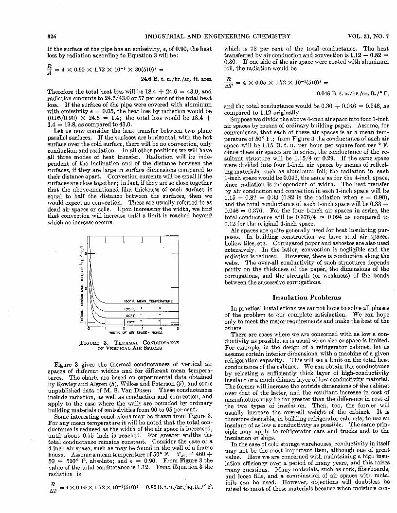
Figure 3 gives the thermal conductances of vertical air spaces of different widths and for different mean tempera- tures. The charts are based on experimental data obtained by Rowley and Algren (S), Wilkes and Peterson (6), and some unpublished data of M. S. Van Dusen. These conductances include radiation, as well as conduction and convection, and apply to the case where the walls are bounded by ordinary building materials of emissivities from 90 to 95 per cent.
Some interesting conclusions may be drawn from Figure 3. For any mean temperature it will be noted that the total con- ductance is reduced as the width of the air space is increased, until about 0.75 inch is reached. For greater widths the total conductance remains constant. Consider the case of a 4-inch air space, such as may be found in the wall of a frame house. Assume a mean temperature of 50 O F. ; Tav. = 460 + 50 = 510" F. absolute; and E = 0.90. From Figure 3 the value of the total conductance is 1.12. From Equation 3 the radiation is
R - =4XO.9Ox 1.72X 10-Q(510)~=0.82B.t.u./hr./sq.ft./oF. AT
which is 73 per cent of the total conductance. The heat transferred by air conduction and convection is 1.12 - 0.82 = 0.30. If one side of the air space were coated with aluminum foil, the radiation would be
- - - 4 X 0.05 X 1.72 X 10-Q(510)s = AT
0.046 B. t. u./hr./sq. ft./'F.
and the total conductance would be 0.30 + 0.046 = 0.346, as compared to 1.12 originally.
Suppose we divide the above 4-inch air space into four 1-inch air spaces by means of ordinary building paper. Assume, for convenience, that each of these air spaces is a t a mean tem- perature of 50" F.; from Figure 3 the conductance of each air space will be 1.15 B. t. u. per hour per square foot per " F. Since these air spaces are in series, the conductance of the re- sultant structure will be 1.15/4 or 0.29. If the same space were divided into four 1-inch air spaces by means of reflect- ing materials, such as aluminum foil, the radiation in each 1-inch space would be 0.046, the same as for the 4-inch space, since radiation is independent of width. The heat transfer by air conduction and convection in each 1-inch space will be 1.15 - 0.82 = 0.33 (0.82 is the radiation when E = 0.90), and the total conductance of each 1-inch space will be 0.33 + 0.046 = 0.376. For the four 1-inch air spaces in series, the total conductance will be 0.376/4 = 0.094 as compared to 1.12 for the original 4-inch space.
Air spaces are quite generally used for heat insulating pur- poses. In building construction we have stud air spaces, hollow tiles, etc. Corrugated paper and asbestos are also used extensively. I n the latter, convection is negligible and the radiation is reduced. However, there is conduction along the webs. The over-all conductivity of such structures depends partly on the thickness of the paper, the dimensions of the corrugations, and the strength (or weakness) of the bonds between the successive corrugations.
Insulation Problems I n practical installations we cannot hope to solve all phases
of the problem to our complete satisfaction. We can hope only to meet the major requirements and make the best of the others.
There are cases where we are concerned with as low a con- ductivity as possible, as is usual when size or space is limited. For example, in the design of a refrigerator cabinet, let us assume certain interior dimensions, with a machine of a given refrigeration capacity. This will set a limit on the total heat conductance of the cabinet. We can obtain this conductance by selecting a sufficiently thick layer of high-conductivity insulant or a much thinner layer of low-conductivity material. The former will increase the outside dimensions of the cabinet over that of the latter, and the resultant increase in cost of manufacture may be far greater than the difference in cost of the two types of insulation. Then, too, the former will usually increase the over-all weight of the cabinet. It is therefore desirable, in building refrigerator cabinets, to use an insulant of as low a conductivity as possible. The same prin- ciple may apply to refrigerator cars and trucks and to the insulation of ships.
I n the case of cold storage warehouses, conductivity in itself may not be the most important item, although one of great value. Here we are concerned with maintaining a high insu- lation efficiency over a period of many years, and this raises many questions, Many materials, such as cork, fiberboards, and loose fills, and a combination of air spaces with metal foils can be used. However, objections will doubtless be raised to most of these materials because when moisture con-
JULY, 1939 INDUSTRIAL AND ENGINEERING CHEMISTRY 827
denses within them, they may deteriorate and lose their insula- tion value. Whatever is used as an insulant for cold storage purposes would have to be vapor-sealed by asphalt or some one of the other means known to the industry. Even so, very few if any of the sealing methods are so tight that they would not permit sufficient moisture to condense within the material over a period of years to reduce the insulation value consider- ably. Cork is usually preferred in such constructions, but even that is far from perfect.
Practically all installations in cold storage warehouses are so made that the insulation material becomes part of the building, and to remove it is expensive. A possible solution is to install insulating materials in the form of panels, each one hermetically sealed as completely as possible, and then to set the panels against the walls, ceilings, and floors so that they can be removed and replaced with ease. If a panel becomes defective in any way, it can readily be replaced, and the insu- lating efficiency of the cold storage plant is maintained a t the highest point a t all times. Panels can also be made with vents on the cold side, which will tend to keep the inside dry, for moisture will evaporate into the cold room and condense on the brine coils.
The question of the heat capacity of insulating materials has been receiving more thought within recent years. I n installations where rapid coolings are required-for example in loading and cooling a refrigerated railroad car-it is desirable to have walls of low heat capacity so that the cooling is not unnecessarily delayed. In furnaces low-heat-capacity walls would permit rapid heating and cooling. To accomplish this, insulating materials of as low a heat capacity together with as high an insulation value as possible, should be selected. I n houses where air conditioning is to be installed, i t is also desir- able to reduce the heat capacity and maintain a high insula- tion value.
Literature Cited (1) Finck, J. L., Bur. Standards J. Research, 5 (Nov., 1930). (2) Heilman, R. H., Trans. Am. SOC. Mech. Engrs., Fuels, Steam
(3) Rowley, F. B., and Algren, A. B., J. Am. SOC. Heating Ventilating Power, 51, 257 (1929).
Enurs., 35, 165 (1929). (4) Van Dusen, M. S.,.and Finck, J. L., Bur. Standards J . Research, 6
(5) Wilkes, G. B., and Peterson, C. M. F., Heating, Piping, Air (March, 1931).
Conditioning, 9, 505-10 (1937).
Silica Aerogel W l r @9
Effect of Variables on Its Thermal Conductivity
The structure, preparation, and previous data on the conductivity of silica aerogel are briefly re- viewed. The failure of aerogel to block radiant heat adequately at high temperature and the need for an opacifying agent is discussed. An investigation showed that admixtures for increasing opacity fall into three classes: (I) red transparent admixtures, (11) opaque nonreflective substances, and (111) material exhibiting a metallic luster. Class I11 is superior, and of this class, silicon was found to be most favorable. Three fourths of a pound of fine ground silicon per cubic foot of aerogel is required for best results. Methods of addition of the silicon are discussed. The effect of the density of the aero- gel on unopacified and opacified aerogel is shown. An increase in density of the aerogel causes greater opacity. This increase in opacity with density causes a lowering of conductivity with unopacified aerogel. If opacified the decrease is not so marked, since radiation is already well blocked by the opaci- fier. Since the conductivity of aerogel is less than that of air, a correct gradation of particle size of the aerogel to give maximum packing results in a low conductivity. A comparison of the values for silica aerogel and still air is given. Tests of aerogel as insulation for refrigerators show that condensation of moisture is prevented presum- ably by decreasing the diffusion rates in the in- sulating chamber.
J. F. WHITE Merrimac Division of the Monsanto Chemical Company, Boston, Mass.
H E term “aerogel” has been applied to a new class of materials that are prepared by drying a gel or gelatinous substance in such manner that the structure of the solid
phase remains unchanged. They were discovered by Kistler and were defined in his patent (1) as a gel having an apparent specific gravity not in excess of 15 per cent of the true spe- cific gravity; further, they are substantially free of liquids and consist essentially of the skeleton of the colloid as i t existed in the original undried gel.
Although the method of preparation was described in the literature (1, S), it will be briefly reviewed since i t has some bearing on the characteristics to be discussed. The scope of this discussion is limited to silica aerogel.
T
Preparation of Silica Aerogel When a solution of sodium silicate is added to a dilute acid
solution, a silica sol is first formed which soon sets to a silica aquagel. This gel is firm, rigid, and transparent. The con- centration can be varied between 3 and 15 per cent silica, and by this means the density of the final product can be regu- lated.
If the aquagel is dried by heating a t normal pressure, a marked shrinkage takes place, and the final result is a hard glasslike product having about one fifth the volume of the
a