HEAT FLUX Federal Aviation SENSITIVITY STUDY IN NBS/OSU/RP
22
Federal Aviation Administration HEAT FLUX SENSITIVITY STUDY IN NBS/OSU/RP/SEAT TEST 2009 October Materials Meeting Materials Working Group Michael Burns, FAA Tech Center October 21 st & 22 nd , 2009
Transcript of HEAT FLUX Federal Aviation SENSITIVITY STUDY IN NBS/OSU/RP

Federal AviationAdministration
HEAT FLUX SENSITIVITY STUDYIN NBS/OSU/RP/SEAT TEST
2009 October Materials Meeting
Materials Working Group
Michael Burns, FAA Tech Center
October 21st & 22nd, 2009

2 2Federal AviationAdministration
Materials Meeting – NBS / OSU UpdatesOctober 21st & 22nd, 2009
Heat Flux Sensitivity Study – OSU/NBS/RP
• 4 Gages Were Selected For Study In OSU/NBS & RP» 1.) MEDTHERM (GARDON) 0-5 BTU» 2.) MEDTHERM (SCHMIDT-BOELTER) 0-5 BTU» 3.) VATELL (GARDON) 0-5 BTU» 4.) HUKSEFLUX (GARDON) 0-5 BTU
• The Gages Were Calibrated By Comparison To A NIST Calibrated HFG
• The Transfer MethodWas Made Using A HeatedGraphite Plate

3 3Federal AviationAdministration
Materials Meeting – NBS / OSU UpdatesOctober 21st & 22nd, 2009
• Step #1• The FAA HFG (NIST Calibration Factor) Was Initially Used To
Set Heat Flux • Step #2
• 4 HFG’s Were Installed In Apparatus And Heat Flux Recorded Using Manufacturers Calibration Factor
• Step #3• 4 HFG’s Were Installed In Apparatus And Heat Flux Recorded
Using NIST Calibration Factor• Step #4
• 4 HFG’s Were Installed And Heat Flux Set Using Manufacturers Calibration Factor
• FAA HFG Was Installed After Each Gage And Heat Flux Recorded Using NIST Calibration Factor
Heat Flux Sensitivity Study – OSU/NBS/RP

4 4Federal AviationAdministration
Materials Meeting – NBS / OSU UpdatesOctober 21st & 22nd, 2009
Heat Flux Sensitivity Study – OSU/NBS/RP
• Calibration Factor (NIST vs. Manufacturer’s)For Each Gage, The Manufacturer’s Calibration Factor Was Found To Be Higher Than The NIST Calibration Factor.
HFG Man. Cal. Factor FAA (NIST) Cal. Factor DeltaMedtherm (Gardon) 0.5889 0.5747 -2.4%Medtherm (Schmidt-Boelter) 0.484 0.4397 -9.2%Vatell 0.56 0.504 -10.0%Hukseflux 0.2689 0.2537 -5.7%

5 5Federal AviationAdministration
Materials Meeting – NBS / OSU UpdatesOctober 21st & 22nd, 2009
NBS Heat Flux Sensitivity StudyManufacturer's Calibration Factor vs. NIST Calibration Factor
0
0.5
1
1.5
2
2.5
3
W/c
m2
Medtherm (Gardon) Medtherm (Schmidt-Boelter) Vatell Hukseflux
-5.6%
8.4%12.0% 10.4%
-8.0%
-1.6% 0.8%4.4%
2.0%
-8.0%-12.0% -10.0%
1.) NBS furnace set to 2.5 W/cm2 using FAA gage (NIST calibrated).
2.) Each of the 4 gages were then installed in the NBS chamber and values recorded using manufacturer's calibration factor.
1.) NBS furnace set to 2.5 W/cm2 using FAA gage (NIST calibrated).
2.) Each of the 4 gages were calibrated against the NIST gage using graphite plate transfer method.
3.) Each of the 4 gages were then installed in the NBS chamber and values recorded using the NIST calibration factor.
1.) Each of the 4 gages were installed in the NBS chamber and heat flux set to 2.5 W/cm2 using manufacturer's calibration factor.
2.) NBS furnace heat flux recorded using FAA gage (NIST calibrated).

6 6Federal AviationAdministration
Materials Meeting – NBS / OSU UpdatesOctober 21st & 22nd, 2009
3 Materials Tested At The Highest And Lowest Heat Flux Found
• Material #1Schneller Panel (Adhesive Sample Face)
• Material #21/8” Honeycomb Panel W/ Textured Face
• Material #33/8” Honeycomb Panel W/ Textured Face
NBS Heat Flux Gage Calibration / Sensitivity study

7 7Federal AviationAdministration
Materials Meeting – NBS / OSU UpdatesOctober 21st & 22nd, 2009
NBS Heat Flux Sensitivity Study2.2 W/cm2 vs. 2.5 W/cm2 (13.6% Delta)
0
50
100
150
200
250
Material #1 Material #2 Material #3
Max
. Ds
2.20 W/cm22.50 W/cm2
1.0% Increase in Max. Ds
32.6% Increase in Max. Ds
37.3% Increase in Max. Ds

8 8Federal AviationAdministration
Materials Meeting – NBS / OSU UpdatesOctober 21st & 22nd, 2009
OSU Heat Flux Sensitivity StudyManufacturer's Calibration Factor vs. NIST Calibration Factor
0
0.5
1
1.5
2
2.5
3
3.5
4
4.5
W/c
m2
Medtherm (Gardon) Medtherm (Schmidt-Boelter) Vatell Hukseflux
1.) OSU heat flux set to 3.5 W/cm2 using FAA gage (NIST calibrated).
2.) Each of the 4 gages were then installed in the OSU and values recorded using manufacturer's calibration factor.
1.) OSU heat flux set to 3.5 W/cm2 using FAA gage (NIST calibrated).
2.) Each of the 4 gages were calibrated against the NIST gage using graphite plate transfer method.
3.) Each of the 4 gages were then installed in the OSU and values recorded using the NIST calibration factor.
1.) Each of the 4 gages were installed in the OSU and heat flux set to 3.5 W/cm2 using manufacturer's calibration factor.
2.) OSU heat flux recorded using FAA gage (NIST calibrated).
-1.4%
4.3%
11.1% 11.1%
-4.0% -5.1%0.0% 4.9%
0.3%
-6.9%-12.3% -12.3%

9 9Federal AviationAdministration
Materials Meeting – NBS / OSU UpdatesOctober 21st & 22nd, 2009
3 Materials Tested At The Highest And Lowest Heat Flux Found
• Material #1Schneller OSU Test Panel
• Material #21” Honeycomb Panel W/ Textured Face
• Material #311/16” Honeycomb Panel W/ Textured Face (Double Peak Material)
OSU Heat Flux Gage Calibration / Sensitivity study

10 10Federal AviationAdministration
Materials Meeting – NBS / OSU UpdatesOctober 21st & 22nd, 2009
OSU Heat Flux Sensitivity StudyAvg. Peak Delta With 14.3% Increase In HF
0
10
20
30
40
50
60
Material #1 Material #2 Material #3
kW/m
2
3.07 W/cm23.51 W/cm2
4.4% Increase 18.3% Increase 15.1% Increase

11 11Federal AviationAdministration
Materials Meeting – NBS / OSU UpdatesOctober 21st & 22nd, 2009
OSU Heat Flux Sensitivity StudyAvg. Time to Peak Delta With 14.3% Increase In HF
0
10
20
30
40
50
60
70
80
90
Material #1 Material #2 Material #3
Seco
nds
3.07 W/cm23.51 W/cm2
26.4% Decrease
12.9% Decrease
12.0% Decrease
12 12Federal AviationAdministration
Materials Meeting – NBS / OSU UpdatesOctober 21st & 22nd, 2009
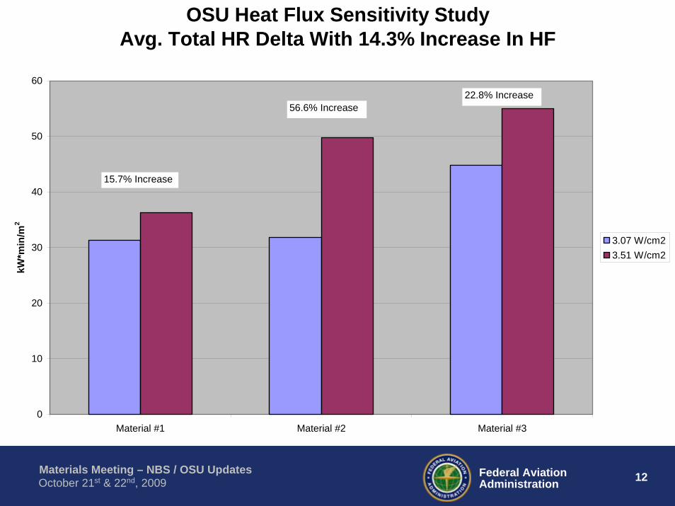
OSU Heat Flux Sensitivity StudyAvg. Total HR Delta With 14.3% Increase In HF
0
10
20
30
40
50
60
Material #1 Material #2 Material #3
kW*m
in/m
2
3.07 W/cm23.51 W/cm2
15.7% Increase
56.6% Increase22.8% Increase

13 13Federal AviationAdministration
Materials Meeting – NBS / OSU UpdatesOctober 21st & 22nd, 2009
RP Heat Flux Sensitivity StudyManufacturer's Calibration Factor vs. NIST Calibration Factor
0
0.25
0.5
0.75
1
1.25
1.5
1.75
BTU
/Ft2
-sec
Medtherm (Gardon) Medtherm (Schmidt-Boelter) Vatell Hukseflux
1.) RP set to 1.5 BTU/Ft2-sec using FAA gage (NIST calibrated).
2.) Each of the 4 gages were then installed in RP and values recorded using manufacturer's calibration factor.
1.) RP set to 1.5 BTU/Ft2-sec using FAA gage (NIST calibrated).
2.) Each of the 4 gages were calibrated against the NIST gage using graphite plate transfer method.
3.) Each of the 4 gages were then installed in the RP and values recorded using the NIST calibration factor.
1.) Each of the 4 gages were installed in the RP and heat flux set to 1.5 BTU/Ft2-sec using manufacturer's calibration factor.
2.) RP heat flux recorded using FAA gage (NIST calibrated).
-10.0%
-1.3%
6.0%2.0%
-12.7%-10.7%
-4.7% -3.3%
8.3%
0.4%
-9.3%
-2.0%

14 14Federal AviationAdministration
Materials Meeting – NBS / OSU UpdatesOctober 21st & 22nd, 2009
LOWER SETTING - 1.361 BTU/Ft2-sec1.) Polyfab – Blocking Layer over 0.6 pcf FiberglassSetpoint Thermocouple1050 DegF 306 DegFAfterflame (seconds) Flame Propagation0 0.750 0.750 0.75
2.) Polyimide film over 2 layers of 0.34 pcf FiberglassSetpoint Thermocouple1051 DegF 319 DegFAfterflame (seconds) Flame Propagation0 0.750 0.750 0.75
3.) Metallized PEEK Film over 2 layers of 0.34 pcf FiberglassSetpoint Thermocouple1051 DegF 319 DegFAfterflame (seconds) Flame Propagation0 0.750 0.750 0.75
RP Heat Flux Gage Calibration / Sensitivity Study

15 15Federal AviationAdministration
Materials Meeting – NBS / OSU UpdatesOctober 21st & 22nd, 2009
RP Heat Flux Gage Calibration / Sensitivity Study4.) Material 1Setpoint Thermocouple1047 DegF 306 DegFAfterflame (seconds) Flame Propagation Pass/Fail0 .75 Pass0 0.5 Pass0 0.75 Pass
5.) Material 2Setpoint Thermocouple1047 DegF 306 DegFAfterflame (seconds) Flame Propagation Pass/Fail0 0.75 Pass0 1.0 Pass0 1.0 Pass
6.) Material 3Setpoint Thermocouple1047 DegF 306 DegFAfterflame (seconds) Flame Propagation Pass/Fail0 0.75 Pass*2.6 0.75 Pass0 0.75 Pass* Burned in the well

16 16Federal AviationAdministration
Materials Meeting – NBS / OSU UpdatesOctober 21st & 22nd, 2009
RP Heat Flux Gage Calibration / Sensitivity Study7.) Material 4Setpoint Thermocouple1047 DegF 306 DegFAfterflame (seconds) Flame Propagation Pass/Fail0 0.5 Pass1.0 0.75 Pass0 0.75 Pass
HIGHER SETTING - 1.624 BTU/Ft2-sec1.) Polyfab – Blocking Layer over 0.6 pcf FiberglassSetpoint Thermocouple*1139 DegF 338 DegF*40 DegF Temperature drop upon opening drawerAfterflame (seconds) Flame Propagation2.5 0.750 0.750 0.75

17 17Federal AviationAdministration
Materials Meeting – NBS / OSU UpdatesOctober 21st & 22nd, 2009
RP Heat Flux Gage Calibration / Sensitivity Study2.) Polyimide film over 2 layers of 0.34 pcf FiberglassSetpoint Thermocouple*1143 DegF 354 DegF*40 DegF Temperature drop upon opening drawerAfterflame (seconds) Flame Propagation0 0.751 0.753 0.75
3.) Metallized PEEK Film over 2 layers of 0.34 pcf FiberglassSetpoint Thermocouple1143 DegF 354 DegFAfterflame (seconds) Flame Propagation0 1.50 1.00 1.75
4.) Material 1Setpoint Thermocouple1142 DegF 350 DegFAfterflame (seconds) Flame Propagation Pass/Fail0 1.0 Pass0 1.0 Pass0 0.75 Pass

18 18Federal AviationAdministration
Materials Meeting – NBS / OSU UpdatesOctober 21st & 22nd, 2009
RP Heat Flux Gage Calibration / Sensitivity Study5.) Material 2Setpoint Thermocouple1142 DegF 350 DegFAfterflame (seconds) Flame Propagation Pass/Fail0 1.25 Pass*6.5 0.75 Fail0 0.75 Pass*Around top of ignitor
6.) Material 3Setpoint Thermocouple1142 DegF 350 DegFAfterflame (seconds) Flame Propagation Pass/Fail0 1.0 Pass0 0.75 Pass0 1.5 Pass
7.) Material 4Setpoint Thermocouple1142 DegF 350 DegFAfterflame (seconds) Flame Propagation Pass/Fail0 1.0 Pass0 1.0 Pass0 1.0 Pass

19 19Federal AviationAdministration
Materials Meeting – NBS / OSU UpdatesOctober 21st & 22nd, 2009
• Compared which method of seat testing would be most affected by heat flux measurements, the handbook method or the rule.
– Two Vatell gages of same range (0-20 BTU) using Manufacturer’s Calibration factor and FAA (NIST) Calibration Factor
• Handbook– Air velocity is restricted to a certain range but the heat flux must be a minimum of 10
BTU/ft2*sec (no maximum).• Rule
– No specification for velocity - Any air velocity that gets you to a specified range of heat flux (10.5 BTU/ft2s +/- 0.5 BTU/ft2s).
• Typically the measured flame temperatures are difficult to achieve, while heat flux is relatively easy to get.
• Measured temperatures at two air velocities and found the temperatures to be in calibration.
• Looked at how measured heat flux changes with air velocity and what the test results would be at the minimum heat flux (10 BTU/ft2*sec) for the FAA (NIST) Calibration Factor and Vatell Calibration Factor.
Seat Test Heat Flux Gage Calibration / Sensitivity Study

20 20Federal AviationAdministration
Materials Meeting – NBS / OSU UpdatesOctober 21st & 22nd, 2009
Measured H.F. vs. Burner Inlet Air Velocity
0
2
4
6
8
10
12
14
0 500 1000 1500 2000 2500Air Velocity, fpm
Hea
t Flu
x, B
TU/ft
2 s
6966 Vatell Slope6966 FAA Slope
10.1 BTU w/ FAA Slope, Vair=1650 fpmMass Loss = 8% -> Pass
10.0 BTU w/ Vatell Slope, Vair=2000 fpmMass Loss = 13.9% -> Fail
Velocity Range for Handbook
H.F. Range for Rule

21 21Federal AviationAdministration
Materials Meeting – NBS / OSU UpdatesOctober 21st & 22nd, 2009
Vair=1650 fpm; H.F.=10.1 BTU/ft2s (FAA Slope) Mass Loss = 8% Pass
Vair=2000 fpm; H.F.=10.0 BTU/ft2s (Vatell Slope) Mass Loss = 13.9% Fail

22 22Federal AviationAdministration
Materials Meeting – NBS / OSU UpdatesOctober 21st & 22nd, 2009
• Results– As inlet air velocity increases, measured heat flux decreases.– Since the handbook has a specified range of air velocities, we ran the tests by the rule, which
has an unlimited velocity range but specified H.F range.– We wanted to see that if you set the burner for 10 BTU/ft2*sec (minimum H.F.) with both of
the slopes, how the results would compare. • Vatell Calibration Factor
– Set Burner to 10 BTU/ft2*sec• Increased air velocity to 2000 fpm
– Tested seat - mass loss of 13.9% (failure)• FAA (NIST) Calibration Factor
– Set burner to 10 BTU/ft2*sec• Decrease of air velocity to 1650 fpm
– Tested seat - mass loss of 8% (pass)• Summary
– Just going by heat flux, if a lab wanted to run at 10 BTU/ft2s, which one would assume would give you the least conservative flame, the test would fail if you used the vatell slope and pass If you used the FAA slope.
– This is opposite of what everyone else is probably seeing, because for the radiant heat sources, a vatell slope will give you a heat flux that is higher than what the true heat flux is with the FAA slope, and materials that pass with a vatell slope will fail with an FAA slope.
– This burner has a convective portion of total heat transfer that is probably close to the magnitude of the radiant portion.
– Gardon gauges are particularly sensitive to convection, and since they are calibrated with a pure radiation source, they may be giving readings that aren't indicative of the actual total heat flux to the surface in the oil burner.