Heat Exchangers - · PDF fileEO5 Identify five (5) factors which affect heat exchanger...
39
Heat Exchangers CONTENT REFERENCES Mark’s Standard Handbook for Mechanical Engineers, Eighth Edition, Edited by Theodore Baumeister, 1979, McGraw-Hill, NY,NY. Handbook of Heat Transfer, Edited by Warren M. Rohsenow and James P. Hartnett, 1973, McGraw-Hill, NY, NY. Heat Exchangers: Design and Theory Sourcebook, Edited by N. H. Afgan and E. U. Schunder, 1979, McGraw-Hill, NY, NY. Heat Exchangers Introduction, 1993, Williams Learning Network, Rockville, Maryland COURSE TERMINAL OBJECTIVE Given a Maintenance activity involving Heat Exchangers (condensers, reheaters, heaters, etc.), describe the inspection, cleaning, repair and rework methods used at PVNGS, in accordance with plant procedures, manufacturer’s technical manuals and standard maintenance practices, as demonstrated by achieving a minimum score of 80% on a written exam. LESSON TERMINAL OBJECTIVE Given a maintenance operation involving heat exchangers, the Plant Mechanic will describe the theory of operation and basic construction of heat exchangers, as demonstrated by achieving a minimum score of 80% on a written examination. LESSON ENABLING OBJECTIVES EO1 State the basic theory of heat transfer. EO2 Define the three mechanisms of heat transfer. EO3 List the four (4) functions performed by heat exchangers. EO4 Classify heat exchangers by their construction. EO5 Identify five (5) factors which affect heat exchanger operation. 1
Transcript of Heat Exchangers - · PDF fileEO5 Identify five (5) factors which affect heat exchanger...
Heat Exchangers
CONTENT REFERENCESMark’s Standard Handbook for Mechanical Engineers, Eighth Edition, Edited by Theodore Baumeister, 1979, McGraw-Hill, NY,NY.Handbook of Heat Transfer, Edited by Warren M. Rohsenow and James P. Hartnett, 1973, McGraw-Hill, NY, NY.Heat Exchangers: Design and Theory Sourcebook, Edited by N. H. Afgan and E. U. Schunder, 1979, McGraw-Hill, NY, NY.Heat Exchangers Introduction, 1993, Williams Learning Network, Rockville, Maryland
COURSE TERMINAL OBJECTIVEGiven a Maintenance activity involving Heat Exchangers (condensers, reheaters, heaters, etc.), describe the inspection, cleaning, repair and rework methods used at PVNGS, in accordance with plant procedures, manufacturer’s technical manuals and standard maintenance practices, as demonstrated by achieving a minimum score of 80% on a written exam.
LESSON TERMINAL OBJECTIVEGiven a maintenance operation involving heat exchangers, the Plant Mechanic will describe the theory of operation and basic construction of heat exchangers, as demonstrated by achieving a minimum score of 80% on a written examination.
LESSON ENABLING OBJECTIVESEO1 State the basic theory of heat transfer.EO2 Define the three mechanisms of heat transfer.EO3 List the four (4) functions performed by heat exchangers.EO4 Classify heat exchangers by their construction.EO5 Identify five (5) factors which affect heat exchanger operation.
1
EO-01 State the basic theory of heat transfer.
Heat is energy in transit from one mass to another because of a temperature difference between the two.
Definitions needed for this course
Heat: a form of energy associated with the motion of atoms or molecules and transferred from a body at a higher temperature to one at a lower temperature.
Temperature: a measure of the ability to transfer heat.
Heat Exchanger: device to transfer heat from one fluid to another.
Heat energy will move from a high energy state to that of a lower energy state. The process will continue until a state of equilibrium is reached. Equilibrium is the energy state where the material is at the same energy level as its surroundings.
Energy will flow from a “hot” material to a “cold” material. “Hot” and “cold” refer to temperature, not the amount of heat. The process continues as long as there is a temperature difference between the materials.
The mechanisms for heat transfer are; conduction, convection (natural and forced) and radiation. The heat transfer processes can work separately or in conjunction with others.
Heat transfer coefficient is a property of each material and each material has its own heat transfer coefficient. It is a measure of the material’s ability to transfer heat. The higher the number value, the more heat transfer through the material. This number is not an additive property. The coefficient values will be affected by scale build-up, film boundary layers, air layers and other material interference.
EO 02 Define the three mechanisms of heat transfer.
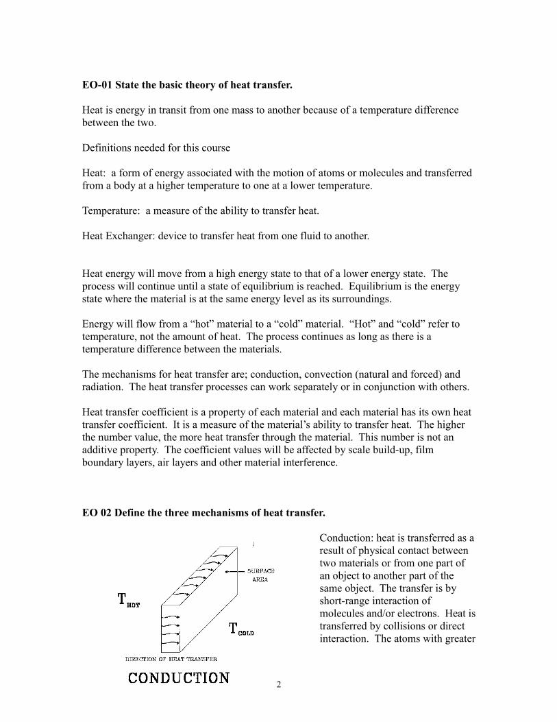
Conduction: heat is transferred as a result of physical contact between two materials or from one part of an object to another part of the same object. The transfer is by short-range interaction of molecules and/or electrons. Heat is transferred by collisions or direct interaction. The atoms with greater
2
thermal energy pass a part of the energy to its neighboring atoms. This process continues from atom to atom. It occurs in all solids, liquids and gases. It is the only method for heat transfer through opaque solids.
If heat is to be conducted through a material there must be a temperature difference between opposite sides of the material. The heat transferred through a material slab by conduction is affected by the surface area of the material, the temperature difference and the time the temperature difference is maintained. These effects are directly proportional, meaning double the value, double the heat transfer. The thickness of the material will inversely affect the heat transfer. The thicker the material, the less heat is transferred.
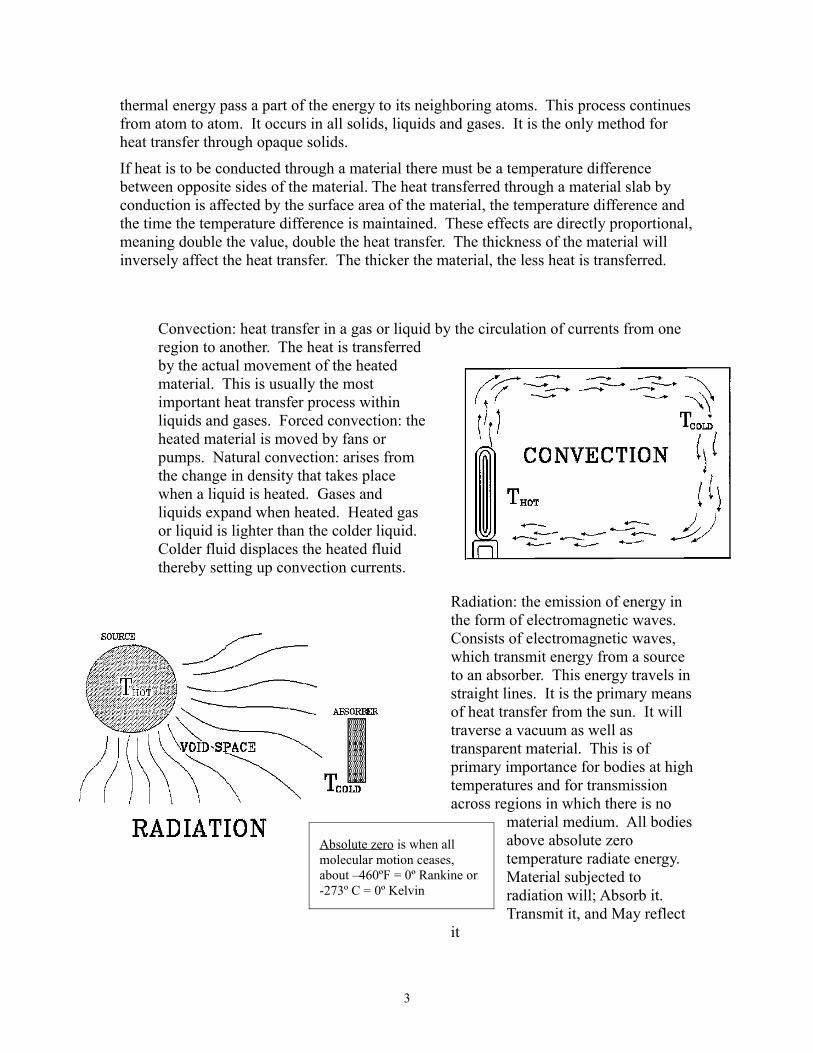
Convection: heat transfer in a gas or liquid by the circulation of currents from one region to another. The heat is transferred by the actual movement of the heated material. This is usually the most important heat transfer process within liquids and gases. Forced convection: the heated material is moved by fans or pumps. Natural convection: arises from the change in density that takes place when a liquid is heated. Gases and liquids expand when heated. Heated gas or liquid is lighter than the colder liquid. Colder fluid displaces the heated fluid thereby setting up convection currents.
Radiation: the emission of energy in the form of electromagnetic waves. Consists of electromagnetic waves, which transmit energy from a source to an absorber. This energy travels in straight lines. It is the primary means of heat transfer from the sun. It will traverse a vacuum as well as transparent material. This is of primary importance for bodies at high temperatures and for transmission across regions in which there is no
material medium. All bodies above absolute zero temperature radiate energy. Material subjected to radiation will; Absorb it. Transmit it, and May reflect
it
3
Absolute zero is when all molecular motion ceases, about –460ºF = 0º Rankine or -273º C = 0º Kelvin

Combination of heat transfer mechanisms. Conduction and convection work together in most processes. Radiant heat transfer has a minor role in the processes of heat transfer in heat exchangers.
An example of the combination of processes is a steam radiator for heating a
room. It uses all three processes. Conduction - heat transfer from the steam to the outside of the radiator. Convection - this is the primary means of heat transfer to the room, evidence of this is by the even heat distribution. Radiation - generates only a small part of heat transfer to heat the room but is a significant factor in your comfort at that temperature.
EO 03 List the four functions performed by heat exchangers
Raise system temperature.
Heaters, for example feedwater heaters
Lower system temperature.
Coolers, for example lube oil coolers
Add latent heat
Convert a solid into a liquid – melting
Remove latent heat
Convert vapor/gas into a liquid - condensation
Convert a liquid into a solid – freezing
Latent heat is the energy added to cause a change in state. A pot of boiling water on a stove is an example of latent heat. The water is boiling at a temperature of 212 degrees F. The steam in the pot is also 212 degrees. The more energy you add, the more water turns to steam, but the temperature of both the water and steam remains the same.
EO 04 Classify heat exchangers by their construction
Direct contact
4
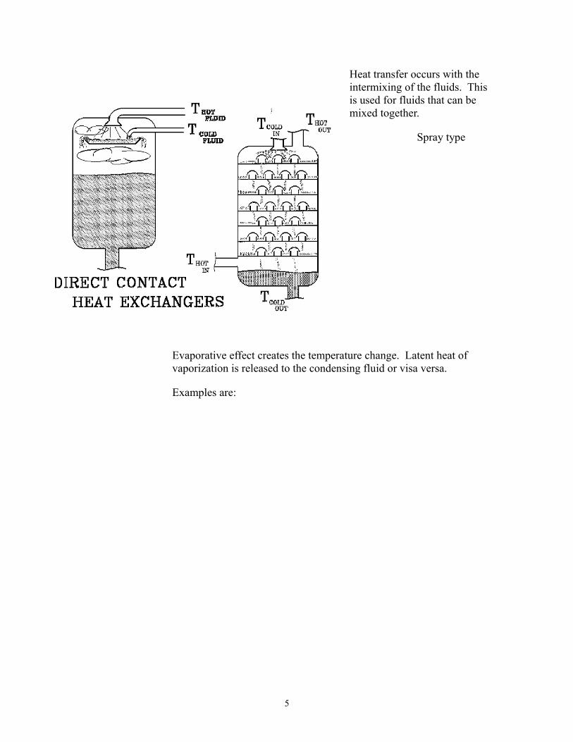
Heat transfer occurs with the intermixing of the fluids. This is used for fluids that can be mixed together.
Spray type
Evaporative effect creates the temperature change. Latent heat of vaporization is released to the condensing fluid or visa versa.
Examples are:
5
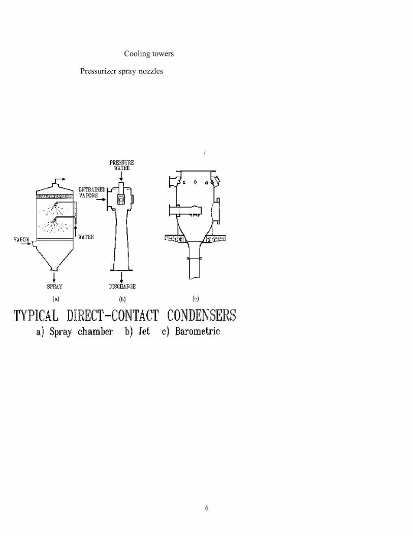
Cooling towers
Pressurizer spray nozzles
6
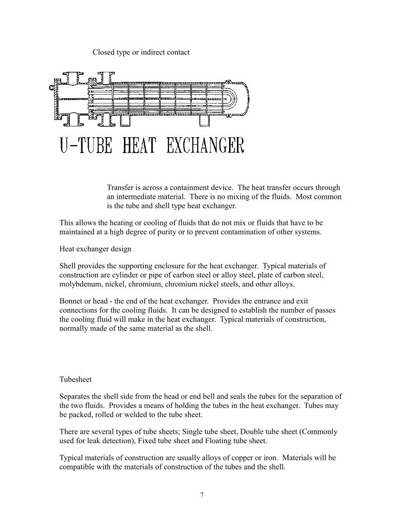
Closed type or indirect contact
Transfer is across a containment device. The heat transfer occurs through an intermediate material. There is no mixing of the fluids. Most common is the tube and shell type heat exchanger.
This allows the heating or cooling of fluids that do not mix or fluids that have to be maintained at a high degree of purity or to prevent contamination of other systems.
Heat exchanger design
Shell provides the supporting enclosure for the heat exchanger. Typical materials of construction are cylinder or pipe of carbon steel or alloy steel, plate of carbon steel, molybdenum, nickel, chromium, chromium nickel steels, and other alloys.
Bonnet or head - the end of the heat exchanger. Provides the entrance and exit connections for the cooling fluids. It can be designed to establish the number of passes the cooling fluid will make in the heat exchanger. Typical materials of construction, normally made of the same material as the shell.
Tubesheet
Separates the shell side from the head or end bell and seals the tubes for the separation of the two fluids. Provides a means of holding the tubes in the heat exchanger. Tubes may be packed, rolled or welded to the tube sheet.
There are several types of tube sheets; Single tube sheet, Double tube sheet (Commonly used for leak detection), Fixed tube sheet and Floating tube sheet.
Typical materials of construction are usually alloys of copper or iron. Materials will be compatible with the materials of construction of the tubes and the shell.
7
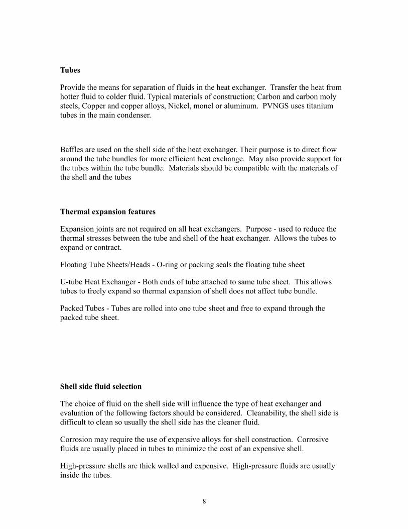
Tubes
Provide the means for separation of fluids in the heat exchanger. Transfer the heat from hotter fluid to colder fluid. Typical materials of construction; Carbon and carbon moly steels, Copper and copper alloys, Nickel, monel or aluminum. PVNGS uses titanium tubes in the main condenser.
Baffles are used on the shell side of the heat exchanger. Their purpose is to direct flow around the tube bundles for more efficient heat exchange. May also provide support for the tubes within the tube bundle. Materials should be compatible with the materials of the shell and the tubes
Thermal expansion features
Expansion joints are not required on all heat exchangers. Purpose - used to reduce the thermal stresses between the tube and shell of the heat exchanger. Allows the tubes to expand or contract.
Floating Tube Sheets/Heads - O-ring or packing seals the floating tube sheet
U-tube Heat Exchanger - Both ends of tube attached to same tube sheet. This allows tubes to freely expand so thermal expansion of shell does not affect tube bundle.
Packed Tubes - Tubes are rolled into one tube sheet and free to expand through the packed tube sheet.
Shell side fluid selection
The choice of fluid on the shell side will influence the type of heat exchanger and evaluation of the following factors should be considered. Cleanability, the shell side is difficult to clean so usually the shell side has the cleaner fluid.
Corrosion may require the use of expensive alloys for shell construction. Corrosive fluids are usually placed in tubes to minimize the cost of an expensive shell.
High-pressure shells are thick walled and expensive. High-pressure fluids are usually inside the tubes.
8
High temperatures reduce the allowable stresses in material. Safety of personnel may require the insulation of the shell if there are high temperatures in the shell. High temperature fluids should be inside the tubes.
The most hazardous or expensive fluid should be placed on the tightest side of the heat exchanger. This is usually the tube side.
If the pressure drop of a fluid is critical and must be accurately predicted, that fluid should be placed inside the tubes. Fluid characteristics inside the tube are more predictable. Pressure drop inside the tube can be calculated with less error.
Classification of heat exchangers
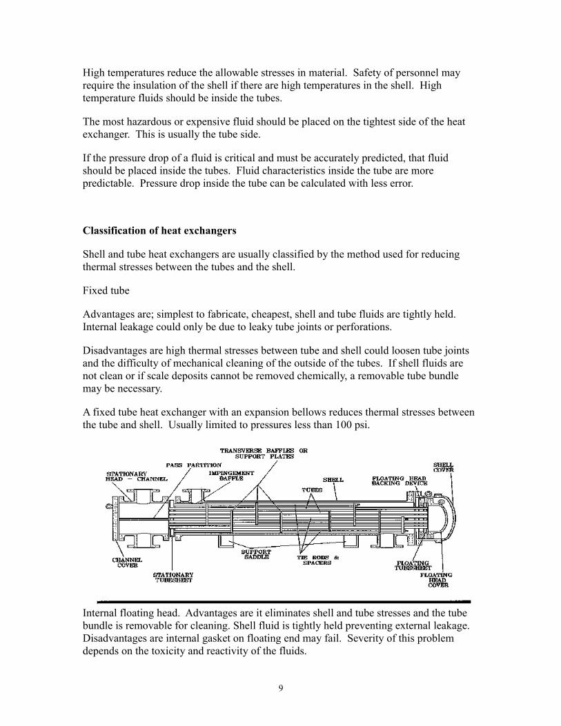
Shell and tube heat exchangers are usually classified by the method used for reducing thermal stresses between the tubes and the shell.
Fixed tube
Advantages are; simplest to fabricate, cheapest, shell and tube fluids are tightly held. Internal leakage could only be due to leaky tube joints or perforations.
Disadvantages are high thermal stresses between tube and shell could loosen tube joints and the difficulty of mechanical cleaning of the outside of the tubes. If shell fluids are not clean or if scale deposits cannot be removed chemically, a removable tube bundle may be necessary.
A fixed tube heat exchanger with an expansion bellows reduces thermal stresses between the tube and shell. Usually limited to pressures less than 100 psi.
Internal floating head. Advantages are it eliminates shell and tube stresses and the tube bundle is removable for cleaning. Shell fluid is tightly held preventing external leakage. Disadvantages are internal gasket on floating end may fail. Severity of this problem depends on the toxicity and reactivity of the fluids.
9
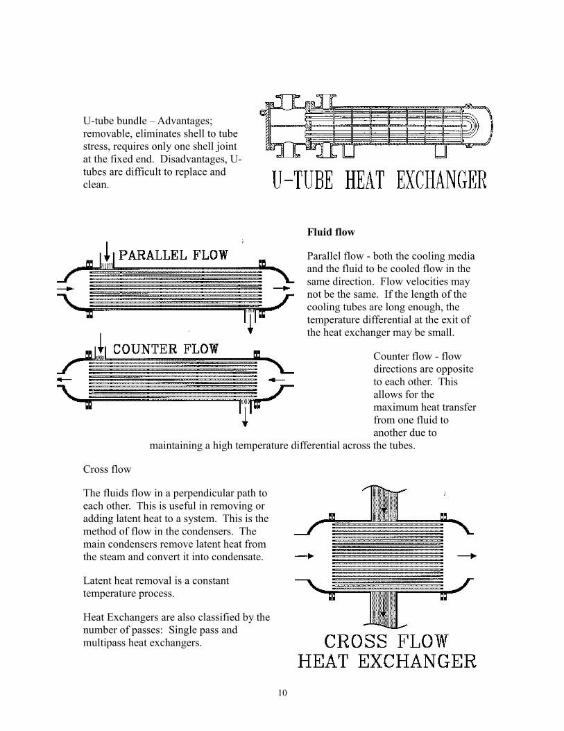
U-tube bundle – Advantages; removable, eliminates shell to tube stress, requires only one shell joint at the fixed end. Disadvantages, U-tubes are difficult to replace and clean.
Fluid flow
Parallel flow - both the cooling media and the fluid to be cooled flow in the same direction. Flow velocities may not be the same. If the length of the cooling tubes are long enough, the temperature differential at the exit of the heat exchanger may be small.
Counter flow - flow directions are opposite to each other. This allows for the maximum heat transfer from one fluid to another due to
maintaining a high temperature differential across the tubes.
Cross flow
The fluids flow in a perpendicular path to each other. This is useful in removing or adding latent heat to a system. This is the method of flow in the condensers. The main condensers remove latent heat from the steam and convert it into condensate.
Latent heat removal is a constant temperature process.
Heat Exchangers are also classified by the number of passes: Single pass and multipass heat exchangers.
10
Construction of a shell and tube heat exchanger
Tube configuration
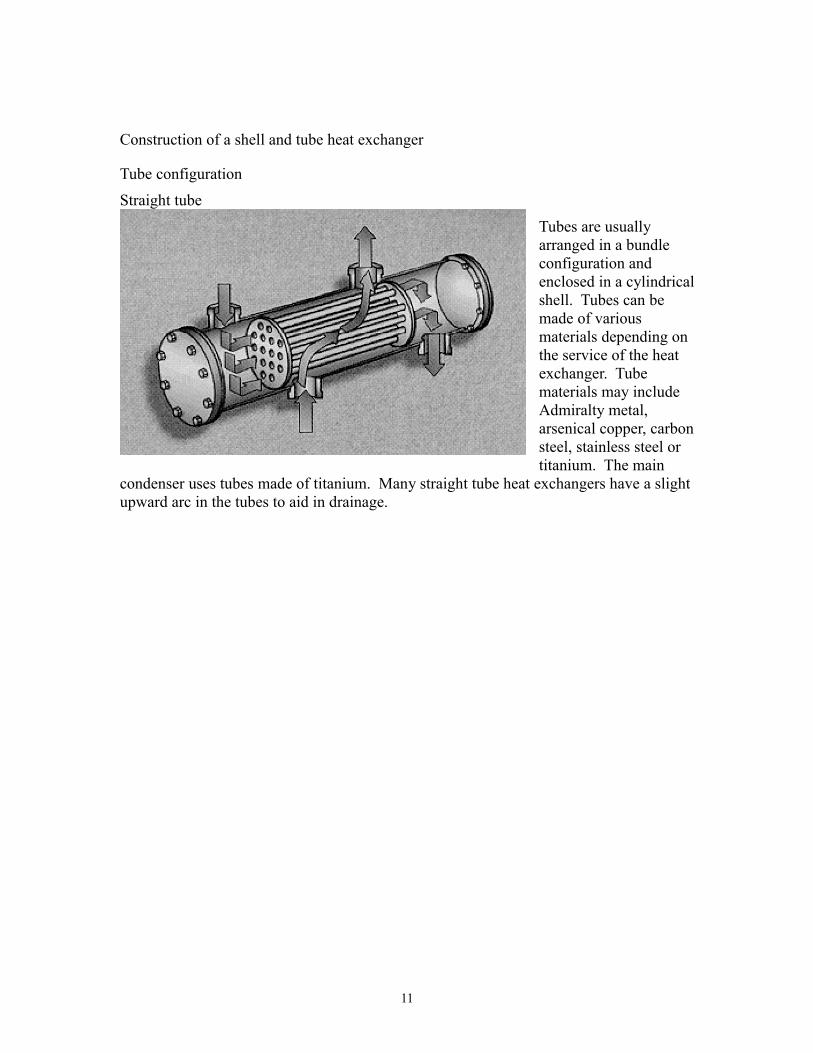
Straight tube
Tubes are usually arranged in a bundle configuration and enclosed in a cylindrical shell. Tubes can be made of various materials depending on the service of the heat exchanger. Tube materials may include Admiralty metal, arsenical copper, carbon steel, stainless steel or titanium. The main
condenser uses tubes made of titanium. Many straight tube heat exchangers have a slight upward arc in the tubes to aid in drainage.
11
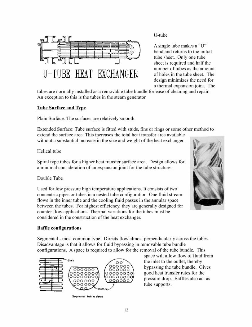
U-tube
A single tube makes a “U” bend and returns to the initial tube sheet. Only one tube sheet is required and half the number of tubes as the amount of holes in the tube sheet. The design minimizes the need for a thermal expansion joint. The
tubes are normally installed as a removable tube bundle for ease of cleaning and repair. An exception to this is the tubes in the steam generator.
Tube Surface and Type
Plain Surface: The surfaces are relatively smooth.
Extended Surface: Tube surface is fitted with studs, fins or rings or some other method to extend the surface area. This increases the total heat transfer area available without a substantial increase in the size and weight of the heat exchanger.
Helical tube
Spiral type tubes for a higher heat transfer surface area. Design allows for a minimal consideration of an expansion joint for the tube structure.
Double Tube
Used for low pressure high temperature applications. It consists of two concentric pipes or tubes in a nested tube configuration. One fluid stream flows in the inner tube and the cooling fluid passes in the annular space between the tubes. For highest efficiency, they are generally designed for counter flow applications. Thermal variations for the tubes must be considered in the construction of the heat exchanger.
Baffle configurations
Segmental - most common type. Directs flow almost perpendicularly across the tubes. Disadvantage is that it allows for fluid bypassing in removable tube bundle configurations. A space is required to allow for the removal of the tube bundle. This
space will allow flow of fluid from the inlet to the outlet, thereby bypassing the tube bundle. Gives good heat transfer rates for the pressure drop. Baffles also act as tube supports.
12
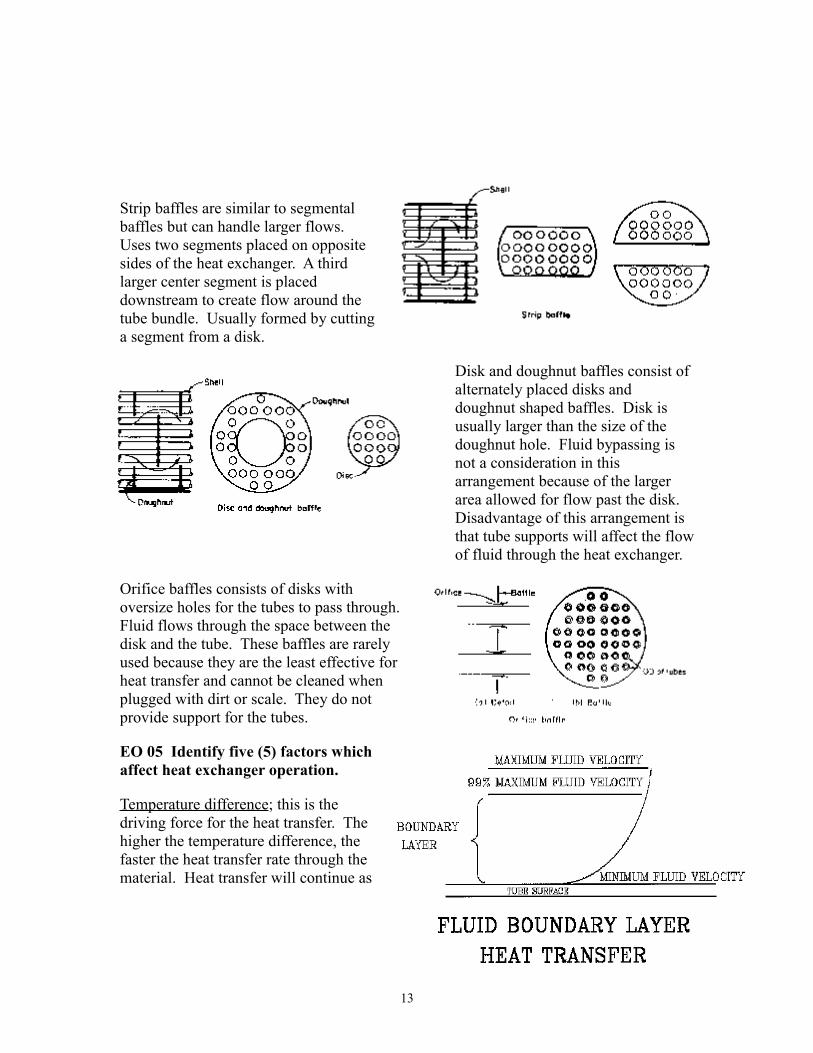
Strip baffles are similar to segmental baffles but can handle larger flows. Uses two segments placed on opposite sides of the heat exchanger. A third larger center segment is placed downstream to create flow around the tube bundle. Usually formed by cutting a segment from a disk.
Disk and doughnut baffles consist of alternately placed disks and doughnut shaped baffles. Disk is usually larger than the size of the doughnut hole. Fluid bypassing is not a consideration in this arrangement because of the larger area allowed for flow past the disk. Disadvantage of this arrangement is that tube supports will affect the flow of fluid through the heat exchanger.
Orifice baffles consists of disks with oversize holes for the tubes to pass through. Fluid flows through the space between the disk and the tube. These baffles are rarely used because they are the least effective for heat transfer and cannot be cleaned when plugged with dirt or scale. They do not provide support for the tubes.
EO 05 Identify five (5) factors which affect heat exchanger operation.
Temperature difference; this is the driving force for the heat transfer. The higher the temperature difference, the faster the heat transfer rate through the material. Heat transfer will continue as
13
long as there is a temperature difference. At low temperature differences there is a low rate of heat transfer.
Fluid film resistance
Boundary layer - When a fluid flows along a surface the velocity changes from zero at the surface to the maximum value in the main stream. Boundary layer thickness is the distance from the surface to the area where the local velocity is 99% of the main stream velocity. The velocity change happens in a short distance, from the edge of the material to the center of the stream. The transition layer is called the boundary layer. In the boundary layer the mixing motion of the fluid is small. Heat transfer is mainly by conduction. Therefore the boundary layer is a major factor in the overall heat transfer.
Film coefficient
Film coefficient is defined as the rate of heat transfer per unit area and unit temperature drop. Relates the heat transfer of the piping surface to the fluid mainstream, noting its dependency on the laminar film layers.
With forced flow (normal condition) the flow is turbulent. Boundary layer thickness can be greatly reduced by increased fluid velocity thus the film coefficient can be greatly reduced. For forced flow of high viscosity fluids such as oil laminar flow may prevail. The boundary layer may extend to the entire flow region.
With free or natural convection fluid motion is induced by differences in fluid specific gravity. Differences in specific gravity are due to temperature differences. The film coefficient for a given fluid and surface configuration depends on: specific heat of the fluids, viscosity, density, thermal conductivity, coefficient of expansion, temperature difference
Surface area
A large surface area will allow for more heat transfer.
Fluid velocity
The faster the flow of fluid, the higher turnover rate of the cooling fluid. Turnover rate is the time required to add enough molecules to completely replace the molecules existing in a confined area. The actual molecules may not all be different, because some of the new ones could go first. Fluid velocity directly affects the boundary layer and the fluid heat transfer.
14
Heat Exchangers
Lesson Number: NMD40-05-XC-002
Lesson Title: Heat Exchanger Inspection and Cleaning
LESSON TERMINAL OBJECTIVE
Given a maintenance activity involving Heat Exchangers the Plant Mechanic will state the steps necessary to clean and inspect heat exchangers as demonstrated by achieving a minimum score of 80% on a written examination.
LESSON ENABLING OBJECTIVES
EO1 State the reasons for cleaning and inspecting heat exchangers.
EO2 Describe the processes used to mechanically clean heat exchanger tubes.
EO3 Describe the basic process used to chemically clean heat exchanger tubes.
EO4 Describe the processes used to perform on-line cleaning of heat exchanger tubes.
EO5 Describe the processes used to clean heat exchanger shells.
EO6 Identify the cleaning methods used on the Main Condensers, MSR's and Feedwater Heaters.
EO7 Describe the general inspection procedures for the Moisture Separator/Reheaters.
EO8 Describe the general inspection procedures for the Main Condensers.
EO9 Describe the general inspection procedures for the Feedwater Heaters.
15
EO-01 State the reason for cleaning and inspecting heat exchangers.
Maintain the operating efficiency of the condensers, MSR's, Feedwater heaters and auxiliary heat exchangers. The heat transfer capabilities of the heat exchanger are calculated and designed with the tubes clean and free of scale, debris or plant growth. The removal of scale from the heat exchanger will increase the heat transfer and make it more efficient. Manufacturers calculate the operation of their heat exchangers based on a certain amount of fouling. Fouling reduces the operational efficiency of the heat exchanger. Efficiency is maintained by keeping the amount of scale and fouling to a minimum.
Minimize the potential for corrosion of the tube materials due to chemical and electrolytic effects and processes. The plant uses all volatile chemistry to control the chemistry of the feedwater and the primary coolant. This is to minimize the potential of scale buildup in the condensers and to minimize solids buildup in the steam generator. The chemistry control also aids in minimizing the amount of corrosion of the heat exchanger construction materials.
VOLATILE chemistry control uses chemicals that boil off in the Steam Generator and condense in the Condenser. These chemicals are in a liquid state in the feed and condensate system and are not susceptible to plating out on the heat exchanger tube surfaces like “solid” chemistry control does.
Inspection for loose or damaged structural components minimizes the possibility of further damage. An extraction steam baffle’s weld cracked and the baffle fell inside a high pressure feedwater heater rupturing fourteen tubes. This required reducing power and securing the feedwater train to allow access to plug the damaged tubes and make weld repairs to the baffle. If the cracks had been discovered during a scheduled outage, hundreds of thousands of dollars could have been saved and the Unit’s capacity factor would have been higher.
MSR impingement screen failures have been identified during refueling outages in all three units. Early detection has prevented further damage, minimizingd the cost of repairs.
Cleaning precautions
There are various safety precautions for cleaning heat exchangers. Do not attempt to clean tubes by blowing them out with steam. This could result in severe expansion of the tube and leakage at the tube to tube sheet joint. If the heat exchanger normally handles flammable materials do not use air to blow out the tubes. When mechanically cleaning the tubes do not use any method that will cause scraping, scarring or cutting of the metal of the tubes. This precaution applies for both the internal and external surfaces of the tubes.
16
EO-02 Describe the processes used to mechanically clean heat exchanger tubes
General information
Mechanical cleaning is the most common cleaning method. Done under shut down conditions when the condenser/heat exchanger is open for service and the tube sheet is accessible. Abrasive methods of tube cleaning should be avoided to minimize the potential for damage to the tube surface
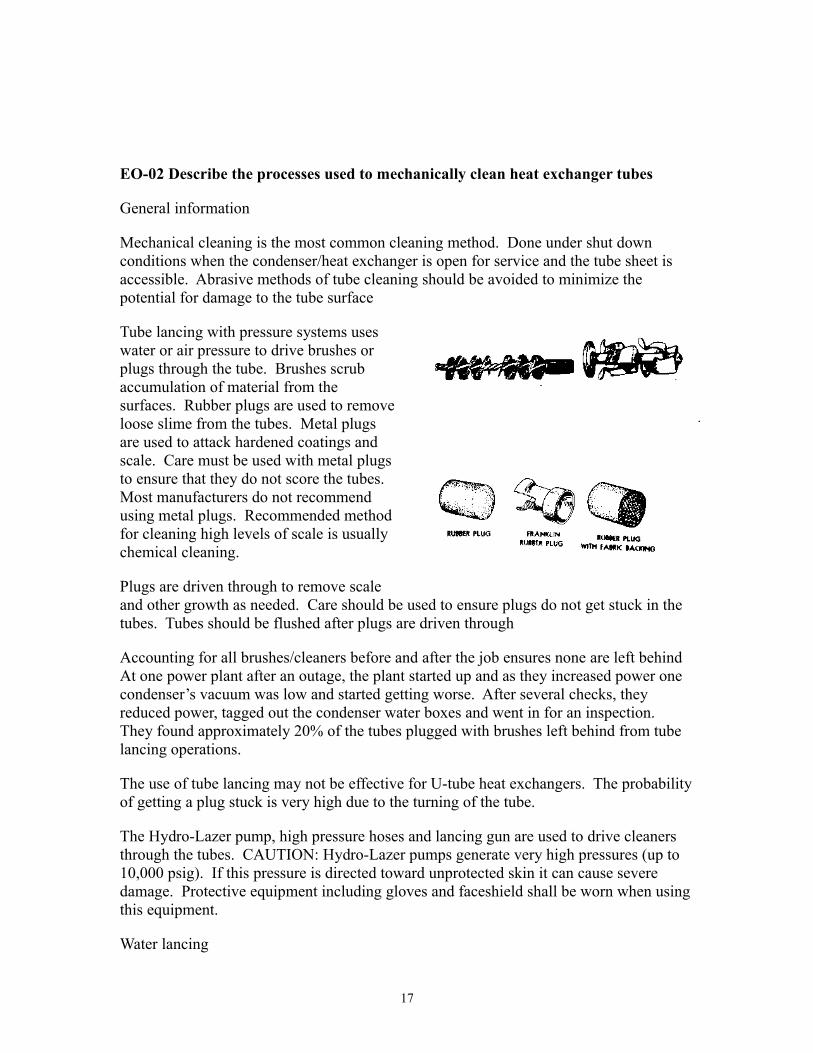
Tube lancing with pressure systems uses water or air pressure to drive brushes or plugs through the tube. Brushes scrub accumulation of material from the surfaces. Rubber plugs are used to remove loose slime from the tubes. Metal plugs are used to attack hardened coatings and scale. Care must be used with metal plugs to ensure that they do not score the tubes. Most manufacturers do not recommend using metal plugs. Recommended method for cleaning high levels of scale is usually chemical cleaning.
Plugs are driven through to remove scale and other growth as needed. Care should be used to ensure plugs do not get stuck in the tubes. Tubes should be flushed after plugs are driven through
Accounting for all brushes/cleaners before and after the job ensures none are left behind At one power plant after an outage, the plant started up and as they increased power one condenser’s vacuum was low and started getting worse. After several checks, they reduced power, tagged out the condenser water boxes and went in for an inspection. They found approximately 20% of the tubes plugged with brushes left behind from tube lancing operations.
The use of tube lancing may not be effective for U-tube heat exchangers. The probability of getting a plug stuck is very high due to the turning of the tube.
The Hydro-Lazer pump, high pressure hoses and lancing gun are used to drive cleaners through the tubes. CAUTION: Hydro-Lazer pumps generate very high pressures (up to 10,000 psig). If this pressure is directed toward unprotected skin it can cause severe damage. Protective equipment including gloves and faceshield shall be worn when using this equipment.
Water lancing
17
Tubes can be water lanced if fouling is minimal. This is done by shooting water through the tubes with no plugs. For short length tubes or smaller heat exchangers manual lancing may be performed. Long handled brushes may be used, brushes can be driven through the tubes. Tubes should be flushed after using the brushes.
Power tube cleaning equipment
Some manufacturers produce power tube cleaning equipment. Cleaning brushes are driven in a rotary motion by a flexible shaft inside a protection sleeve (similar to a speedometer cable) called a whip. The whip is driven by an air motor that may be mounted in a case containing the motor, air and water regulators and gauges. Water is fed through the drive shaft sleeve to provide cooling and lubrication to the whip and provides flushing for the brush on some models.
EO-03 Describe the basic process used to chemically clean heat exchanger tubes
The basic purpose of chemical cleaning is to clean areas that are not easily accessible or are totally inaccessible. It can also dissolve some types of scale easier than mechanical cleaning can remove it.
Chemical cleaning of heat exchanger tubes can be accomplished in a shutdown mode. Chemicals used should be compatible with the materials of construction to minimize any chemical reactions between heat exchanger materials and cleaning compounds.
Heat exchanger should be completely flushed after cleaning process is complete. Remove any residual chemicals that could contribute to tube wear. Avoid cross contamination of fluids in heat exchanger.
If acids are used, neutralizers may be needed to stop the chemical reactions. A flush is then performed until samples meet the chemistry specs.
Some possible cleaning solutions may include; hot alkaline solutions can be used to remove oily deposits. A weak inhibited acid solution is used to remove calcium deposits or silica scale. Hot wash oil or light distillate circulated through tube side at high velocity may be used to remove sludge or similar soft deposits. Hot fresh water is effective for removing soft salt deposits.
There are many commercial cleaning chemicals available. They may have to be analyzed by consulting chemistry experts and manufacturer’s representatives Manufacturer’s technical manual should be consulted to ensure that materials used are compatible with the materials of construction.
Basic steps for chemical cleaning of heat exchangers
Determine chemicals to be used. Engineering and Chemistry evaluate the chemicals to be used. Ensure they will not damage the materials of the heat exchanger. Ensure compatibility with the system.
18
Set up flushing equipment. Usually skid mounted, mixing tanks, auxiliary pumps, hose connections, heaters, filters. Isolate the heat exchanger from the fluid systems. Perform a flush to remove any fluids that may react with the cleaning chemicals. Connect flushing equipment and introduce the chemicals. Perform the required operations for the cleaning process. Operate pumps or heating of the system, etc. Remove the chemical solutions from the heat exchanger after the recommended cleaning time. Properly dispose of chemical solutions in accordance with plant procedures. Perform flushes of the heat exchanger to remove all traces of the cleaning chemicals. Chemical tests may be performed to verify that all chemicals have been removed. If cleaning is satisfactory the system may be restored and returned to service. If heat exchanger is highly scaled, several chemical cleaning cycles may be required. If chemical cleaning does not remove the scale, mechanical cleaning may be necessary.
EO-04 Describe the processes used to perform on-line cleaning of heat exchanger tubes
PVNGS has no on-line cleaning system for the condensers and heat exchangers. Some plants have on-line cleaning systems to clean tubes due to the source of cooling that they have available to them.
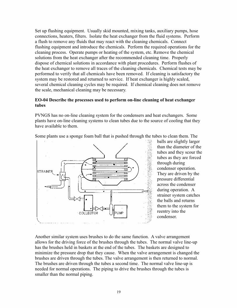
Some plants use a sponge foam ball that is pushed through the tubes to clean them. The balls are slightly larger than the diameter of the tubes and they scour the tubes as they are forced through during condenser operation. They are driven by the pressure differential across the condenser during operation. A strainer system catches the balls and returns them to the system for reentry into the condenser.
Another similar system uses brushes to do the same function. A valve arrangement allows for the driving force of the brushes through the tubes. The normal valve line-up has the brushes held in baskets at the end of the tubes. The baskets are designed to minimize the pressure drop that they cause. When the valve arrangement is changed the brushes are driven through the tubes. The valve arrangement is then returned to normal. The brushes are driven through the tubes a second time. The normal valve line-up is needed for normal operations. The piping to drive the brushes through the tubes is smaller than the normal piping.
19
EO-05 Describe the processes used to clean heat exchanger shells
The necessity of cleaning the shell side of a heat exchanger depends on the fluid that passes through it. The need to clean the shell side of the main condenser is determined by the quality of the steam that passes through. Usually high quality steam with a minimum amount of carryover from the steam generator so potential for scale buildup is small.
Shell side of an oil cooler, that has oil on the shell side, can be chemically cleaned if the material of construction will not be affected by the chemicals.
Abrasive (mechanical) cleaning methods for the shell side of a heat exchanger should not be used on the tube bundle. Normally, non-abrasive methods are used on the tube bundles. Chemical cleaning by soaking in chemical baths and flushing down after the soak to remove chemicals. Pressure sprayers can be used to remove soft scales and sludge. Steam cleaners can be used on certain heat exchanger tube bundles if structural strength of bundle is sufficient. Caution – the high temperatures of steam cleaning can cause thermal expansion of the tube bundle and cause tubes to loosen from the tube sheet.
EO-06 Identify the cleaning methods used on the Main Condensers, MSR’s and Feedwater Heaters at PVNGS
Main condenser cleaning methods
Tube side cleaning includes the water boxes and the tubes. Epoxy coating inside the water boxes minimizes cleaning required. General cleaning is done using buckets, brooms, dust pans, rags, etc. Tube cleaning using the Hydro-Lazer to water lance the tubes and to lance the tubes using sponge plugs was performed during construction. System cleanliness has not required frequent tube cleaning since construction.
Shell side (condensate) of the condenser should not require cleaning due to the quality of the steam the plant uses. We use volatile chemistry control in the steam generators which minimizes scale buildup. Shell side is a Zone IV and class “C” cleanliness; therefore during inspections and repairs, general cleaning may be required to maintain class cleanliness. Foreign Material Exclusion inspections are required prior to close out.
MSR cleaning methods
The MSR technical manual does not have any recommended cleaning methods. Since the steam quality is high on both the tube and shell sides, same quality steam as Main Condenser shell side is on both sides, scale formation has not been a problem.
Feedwater Heater cleaning methods
20
Westinghouse tech manual recommends chemical analysis of scale formation to determine the type and strength of cleaners to use. They recommend using inhibited acid solutions and flushing equipment to clean both the tube and shell sides.
EO-07 Describe the general inspection procedures for the Moisture Separator/Reheaters
Ops engineering, ISI, is responsible for performing the MSR inspections. Maintenance opens the MSR’s and assists in the inspection process. MSR tech manual has instructions for performing inspections including lists of items to be inspected.
Basic construction
21
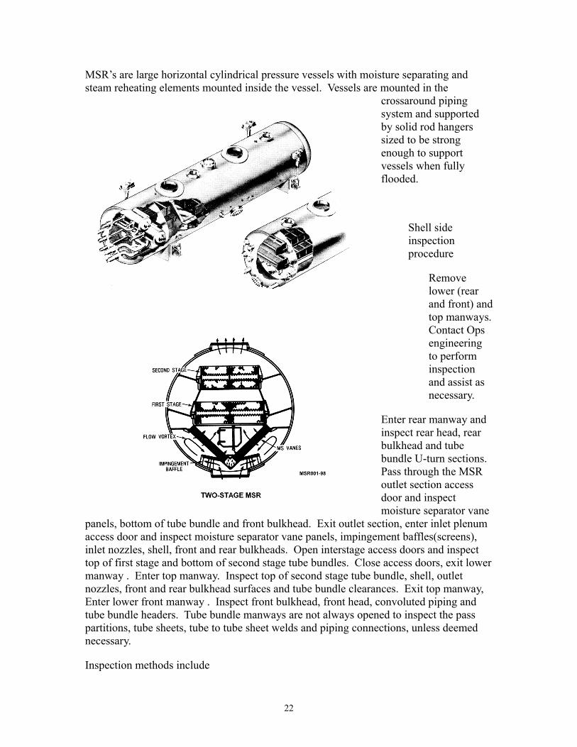
MSR’s are large horizontal cylindrical pressure vessels with moisture separating and steam reheating elements mounted inside the vessel. Vessels are mounted in the
crossaround piping system and supported by solid rod hangers sized to be strong enough to support vessels when fully flooded.
Shell side inspection procedure
Remove lower (rear and front) and top manways. Contact Ops engineering to perform inspection and assist as necessary.
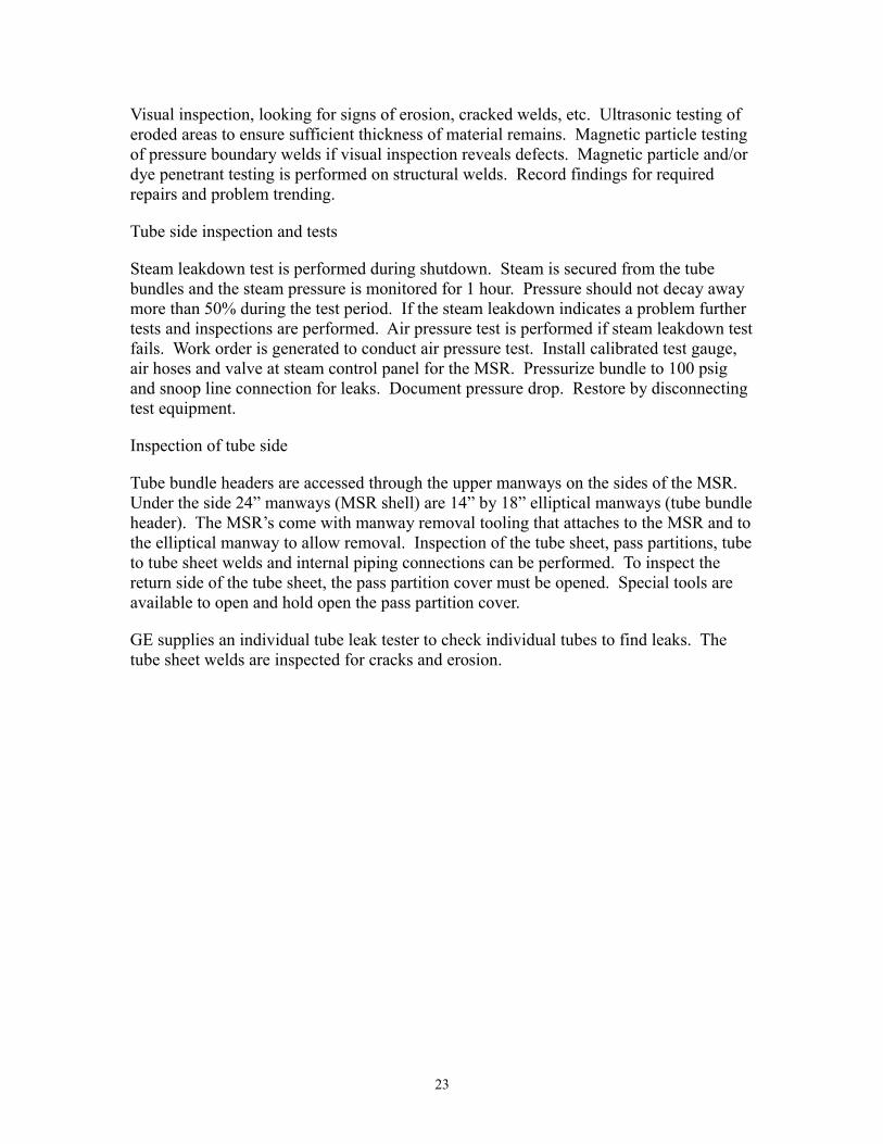
Enter rear manway and inspect rear head, rear bulkhead and tube bundle U-turn sections. Pass through the MSR outlet section access door and inspect moisture separator vane
panels, bottom of tube bundle and front bulkhead. Exit outlet section, enter inlet plenum access door and inspect moisture separator vane panels, impingement baffles(screens), inlet nozzles, shell, front and rear bulkheads. Open interstage access doors and inspect top of first stage and bottom of second stage tube bundles. Close access doors, exit lower manway . Enter top manway. Inspect top of second stage tube bundle, shell, outlet nozzles, front and rear bulkhead surfaces and tube bundle clearances. Exit top manway, Enter lower front manway . Inspect front bulkhead, front head, convoluted piping and tube bundle headers. Tube bundle manways are not always opened to inspect the pass partitions, tube sheets, tube to tube sheet welds and piping connections, unless deemed necessary.
Inspection methods include
22
Visual inspection, looking for signs of erosion, cracked welds, etc. Ultrasonic testing of eroded areas to ensure sufficient thickness of material remains. Magnetic particle testing of pressure boundary welds if visual inspection reveals defects. Magnetic particle and/or dye penetrant testing is performed on structural welds. Record findings for required repairs and problem trending.
Tube side inspection and tests
Steam leakdown test is performed during shutdown. Steam is secured from the tube bundles and the steam pressure is monitored for 1 hour. Pressure should not decay away more than 50% during the test period. If the steam leakdown indicates a problem further tests and inspections are performed. Air pressure test is performed if steam leakdown test fails. Work order is generated to conduct air pressure test. Install calibrated test gauge, air hoses and valve at steam control panel for the MSR. Pressurize bundle to 100 psig and snoop line connection for leaks. Document pressure drop. Restore by disconnecting test equipment.
Inspection of tube side
Tube bundle headers are accessed through the upper manways on the sides of the MSR. Under the side 24” manways (MSR shell) are 14” by 18” elliptical manways (tube bundle header). The MSR’s come with manway removal tooling that attaches to the MSR and to the elliptical manway to allow removal. Inspection of the tube sheet, pass partitions, tube to tube sheet welds and internal piping connections can be performed. To inspect the return side of the tube sheet, the pass partition cover must be opened. Special tools are available to open and hold open the pass partition cover.
GE supplies an individual tube leak tester to check individual tubes to find leaks. The tube sheet welds are inspected for cracks and erosion.
23
EO-08 Describe the general inspection procedures for the Main Condensers
Ops engineering (ISI) is responsible for performing the inspections. Maintenance opens the condenser and assists in the inspection process.
Construction of the main condenser
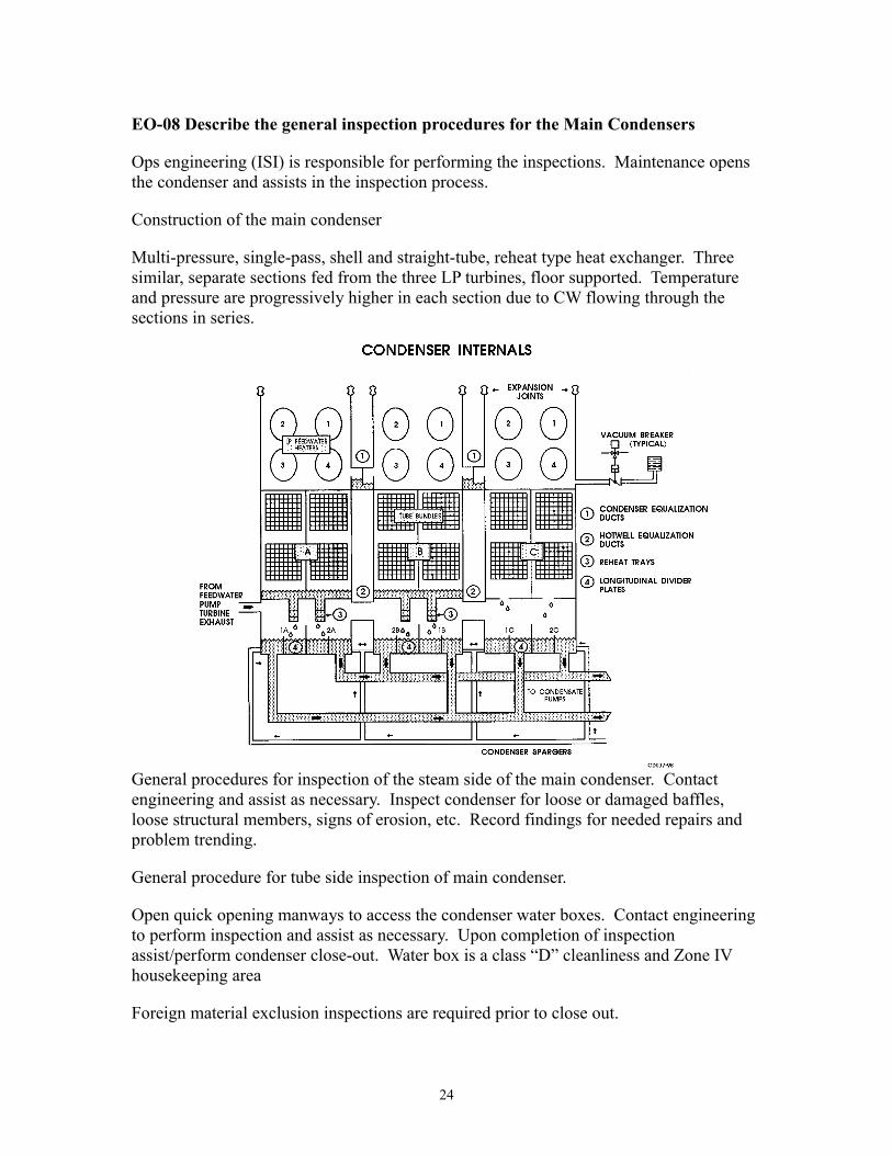
Multi-pressure, single-pass, shell and straight-tube, reheat type heat exchanger. Three similar, separate sections fed from the three LP turbines, floor supported. Temperature and pressure are progressively higher in each section due to CW flowing through the sections in series.
General procedures for inspection of the steam side of the main condenser. Contact engineering and assist as necessary. Inspect condenser for loose or damaged baffles, loose structural members, signs of erosion, etc. Record findings for needed repairs and problem trending.
General procedure for tube side inspection of main condenser.
Open quick opening manways to access the condenser water boxes. Contact engineering to perform inspection and assist as necessary. Upon completion of inspection assist/perform condenser close-out. Water box is a class “D” cleanliness and Zone IV housekeeping area
Foreign material exclusion inspections are required prior to close out.
24
EO-09 Describe the general inspection procedures for the Feedwater heaters
Operating parameters give indications of the performance of the Feedwater heaters. When problems are identified or suspected a work order is generated to access the heater for inspection.
Construction of HP feedwater heaters
Shell and U-tube, extraction steam on shell side, Feedwater flows into bottom of tubes and exits from the top. Heaters #6 and #7 are equipped with drain coolers.
Construction of LP feedwater heaters
Three parallel trains each consisting of four heat exchangers. Separate set of upper and lower tube bundles and hemispherical head. Condensate enters through lower tube bundle and exits through upper bundle.
Diaphragms on feedwater heaters on both HP and LP heaters ¼” steel plates welded on under manway serve as a gasket, not a pressure boundary.
Inspection of tube side
Manway event at Seabrook
During the week of 6/8/98, two feedwater heaters were scheduled to be removed from service for tube plugging. Power was reduced to 90% to accommodate removing the heaters from service and work was begun on the first heater. The morning of 6/11/98, the plant was shutdown due to an inoperable Control Building Air Conditioning System, and permission was requested to begin work on the second feedwater heater that was not yet isolated or tagged out. The work that was authorized was to prepare for opening the heater and plugging tubes. Included in the scope of preparatory work was removal of the heater manway. A tagout was not done for the preparatory work because personnel felt they were not breaching the pressure boundary. On 6/11/98, a maintenance crew removed the 18” diameter, pressure retaining, blind flange manway cover from an in-service feedwater heater. The feedwater system pressure and temperature were approximately 500 psi and 90F. Beneath the manway cover, the manway is sealed utilizing a ¼” thick steel plate diaphragm, which is welded onto the manway opening. The diaphragm acts only as a gasket that is sealed by means of welding. This diaphragm remained intact when the manway cover was removed. However, it did show signs of bulging and deformation due to system pressures. If the diaphragm had failed, it is likely that serious injury to the maintenance crew would have been the result.
At the time of the event, the plant was shutdown with the Condensate System in service and flowing through the feedwater heater. The maintenance crew recognized the abnormal condition and secured the job.
Ensure adequate conditions are established prior to beginning work.
25

Under the manway is a welded diaphragm. Diaphragm is just a gasket – not a pressure retainer. It must be ground out to access the heater. Remove pass partition bolting, partitions and gaskets. Contact Ops engineering for inspection and assist as necessary. Eddy current testing and video boroscope inspections are used to inspect the tubes. Record findings in work order for needed repairs, generate the necessary work orders and EER’s. Tube plugging and replacement is performed per EER. When work is complete, close out the heater (FME inspection), weld in diaphragm, Weld requires NDE. After NDE, re-install the manway and tighten per tech manual instructions.
26

Heat Exchangers
Lesson Title: Heat Exchanger Tube Maintenance
LESSON TERMINAL OBJECTIVE
Given a heat exchanger maintenance activity the maintenance mechanic will describe the methods used to locate leaking tubes, and to plug/rework/replace the heat exchanger tubes, as demonstrated by achieving a minimum score of 80% on a written examination.
LESSON ENABLING OBJECTIVES
EO01 Identify the common causes of heat exchanger tube leakage.
EO02 Describe the methods used to locate leaking heat exchanger tubes.
EO03 Describe the general method used to plug leaking heat exchanger tubes.
EO04 Describe the method used to plug leaking Feedwater Heater tubes.
EO05 Describe the method used to plug leaking Main Condenser tubes.
EO06 Describe the method used to plug leaking Moisture Separator/Reheater tubes.
EO07 Describe the methods of removing tubes from heat exchangers.
EO08 Describe the process used to replace tubes in heat exchangers
EO09 Describe the process of rolling tubes in tube sheets.
EO10 Describe the general procedure to replace a heat exchanger tube bundle.
27
EO-01 Identify the common causes of heat exchanger tube leakage
There are many causes for leaks. Leaks are most commonly located at or near the tube-to-tubesheet junction for several reasons. The most turbulent flow is at the inlet of the tubes. There are also often dissimilar metals between the tube and tube sheets. The seal weld, packing, or rolling may not seal completely either.
Leaks also occur in an area where the outside fluid (if high velocity) could erode the tubes where it enters the shell side. Foreign material could cause leakage anywhere along the tubes also. A shock load (like water hammer) could create a leak anywhere in the heat exchanger
Erosion of the tube by the fluid flow in the heat exchanger, both tube and shell sides. Example: in the main condenser, Westinghouse welded stainless steel plates to the carbon steel support stanchions to deflect the incoming high energy fluid from directly impinging on the tubes. The dissimilar thermal expansion rates of the carbon and stainless steels caused the welds to break. Pieces of plate were blown into the tubes puncturing them and the high-energy fluid then directly eroded the tubes causing more damage.
Corrosion of the tubes from improper chemistry control, excessive stresses, failure or inadequate cathodic protection, failure to maintain sacrificial anodes. An example of stress corrosion failure is in the feedwater heater tubes. We are experiencing linear crack failures in the feedwater heater tubes. It is stress corrosion cracking caused in part by the different thermal expansion of the stainless steel tubes and the carbon steel shell of the heaters.
Mechanical shear caused by failed structural members. Low pressure feedwater heaters in the top of the condenser originally had stainless steel lagging on them held away from the surface by spot welded studs. Their purpose was to provide some insulation to prevent heat loss from the heater. Vibration loosened the lagging and then the studs started puncturing them allowing more vibration. The weakened and perforated pieces started breaking off and sheared tubes in the main condenser.
Shear caused by foreign objects in heat exchanger
SOER 82-12 Steam Generator Tube Ruptures
R. E. Ginna Plant. On January 25, 1982, a steam generator tube rupture occurred at full power conditions. Reactor coolant system pressure decreased rapidly, causing a reactor trip on low pressure and initiating safety injection. The “B” SG safety valve opened five times during the event, once for approximately an hour. Finally, operators managed to cool down the RCS using the ADV’s on the good SG. A loose metal object caused the tube rupture. This rupture had an estimated leak rate of 630 GPM through a ¾” by 4” long axial fishmouth that was approximately 3” above the tube sheet.
28
Prairie Island 1. On October 2, 1979, while operating at power a steam generator tube rupture event occurred. A steel coil spring punctured the tube, resulting in a leak rate of 390 GPM through a ¾” by 1 ½” long fishmouth that was also located approximately 3” above the tube sheet.
Both of these incidents occurred from loose metal objects in the secondary side of the steam generator, introduced by failed mechanical components from the feed and condensate systems being carried into the SG and tooling or other foreign objects left in the system after maintenance.
Vibration can also induce mechanical failure. The main condenser tube support stanchions are spaced about three feet apart. This is too far to prevent vibration. The vibration causes thinning of the tubes at the tube support plates. To prevent tube failures, plastic cushions have been inserted between the tubes to dampen vibrations.
Tube to tube sheet leaks have several common causes. Packing leaks on heat exchangers with packed tubes. Leaks from rolled tubes. Tubes rolled less than optimum amount of tube wall reduction do not have sufficient holding power. Tubes over rolled have excessive tube wall reduction and have experienced excessive work hardening.
Heat exchangers with welded tubes may experience weld failures due to excessive stresses both mechanical and thermal at the welded joint. This can take the form of stress cracking corrosion at the weld.
Leaks from floating tube sheet connections can be caused by, gasket or O-ring failures, scale/foreign material.
The following are generic indications of a leaking tube in a heat exchanger. Increasing or decreasing inventory for one of the fluids. Alarm indication if associated with any of the fluids under leak detection. Nuclear cooling water has a radiation monitor to detect leakage. TDS alarm in feedwater in case of main condenser leak.
Indications of minor tube leakage in steam generators; Main steam line radiation high, Condenser off gas radiation high, Steam generator blowdown radiation high, Charging/letdown flow mismatch, Decreasing VCT level, Secondary side sample activity high.
An increase on any hotwell sodium indication points to a leak in the main condenser. A corresponding increase in hotwell cation conductivity should also be seen. An auto isolation of the condensate reject valve due to conductivity may occur. There may be an increase in the hotwell level depending on the size of the tube leak. These indications will be seen in the control room.
Besides internal leakage in heat exchangers, external leakage may occur. External leakage may result in flooding as covered in SOER 85-5.
Crystal River 3 – With the unit at 100% power, one of the service water heat exchangers was opened up for maintenance. A solenoid valve failed, which failed a fourteen-inch air
29
actuated heater supply valve open. The flooding from the disassembled heat exchanger was estimated at 65,000 GPM and flooded the turbine building to a level of six inches in approximately five minutes.
The plant has had its share of flooding incidents.
August 14, 1986, Unit 1 – The main circulating water system was being returned to service following some condenser inspections and repairs. The manways on the south side of condenser 1A had been verified secured; however, when the system was started an estimated 50,000 – 100,000 gallons poured out of the manways flooding the turbine building to a level of four to five inches. It was believed that the manways were not properly secured.
Flooding is a safety concern because it can disable safety equipment needed to safely shut down the plant. The damage caused by flooding can be wide spread and occur over a short period of time.
Personnel need to be aware of the impact flooding could have on the plant. It could affect the safe operation of the plant. Which evolutions increase the vulnerability to flooding need to be recognized. Areas and equipment susceptible to flooding should be evaluated. Methods to reduce the risks and effects of flooding should be considered. Operator actions to prevent/control flooding should be addressed.
EO-02 Describe various methods that can be used to locate leaking tubes in heat exchangers.
The method of locating tube leaks depends on the system and the characteristics of the fluid that is leaking and the size of the leak. Test procedures for locating leaks may be implemented during the course of normal operations or at prescribed times in the life of the plant. PVNGS uses several methods of monitoring and locating heat exchanger tube leaks. Ops engineering uses eddy current testing. Systems engineering uses methods that include helium monitoring. Major leaks in the condenser tubes can be found just by listening, you can hear it whistling. Plastic film and soap bubbles can also be used to find leaking tubes.
Helium testing
This is the use of an inert gas introduced into the system and then monitored by some device. The usual monitoring is by gas spectroscopy to determine the presence of the inert gas that is used to detect the leak. Helium leak detection of main condenser tube leaks is commonly performed with the unit running but downpowered and vacuum in the condenser.
Set up
The detector is connected to the vacuum pump discharge.
30
A small syringe of helium is injected in a valve connection on the shell side of the condenser (test shot). This tests the detector and gives an indication of the time delay of detection. Usually there is a 30 second or more delay from the test shot until detection.
Set up communications with personnel at the helium detector. Enter water box and start wide area testing. Start at the top and start spraying the tubes going in a pattern and shooting every tube. As soon as the detector sees something, stop, mark the area shot in the last 30 seconds or so, and let the detector clear. It usually takes a while for the detector to clear, so it is a good time to come out of the water box and cool off.
Once the detector has cleared, start again by shooting one tube at a time in the area marked and waiting approx. 30 seconds for detection. When the leaking tube is found, double check it being careful that only the tube being tested gets helium. The detector is very sensitive and may pick up background helium from adjacent tubes. Mark the tube and start the rapid detection process again until all the tubes have been checked.
Some systems may have alarms associated with them to detect a leak across the heat exchangers. These include the radiation monitors on the main steam system and the sodium monitoring on the main condensers.
Eddy current testing. The manufacturer recommends that testing of the steam generator tubes be done periodically. The test is performed by the use of an electronic test device that has a probe. The probe is mechanically pushed through the tubes and an electrical signal is generated (eddy current) and monitored to give a graphic indication of the tube. The graphic interpretation of the tube is compared to a series of test standards that were made on the same type of material as the tubes being tested. This will determine the amount of wear, erosion or damage to the tubes.
Soap film, A soap solution or other high surface tension solution is applied to tube ends. Both ends of the tube must be painted at the same time. Soap film is only reliable for about five minutes. The shell side of the heat exchanger is then pressurized or placed under a slight vacuum. The bubble film on leaking tubes will be disturbed. A burst bubble or sucked in film is not a positive indication of tube leak. This type of test has to be repeated to verify that the film was disturbed by a leak and not other causes.
Plastic film material testing. A slight vacuum is applied to the shell side of the heat exchanger. A plastic film material is placed on the tube sheet. The thin slick brown trash bags used here are made of the type of plastic that works very well. A leaking tube will be indicated by a depression of the film material. This method does not work well on the main condensers because the tubes are not flush with the tube sheet.
Ultrasonic testing
This is the use of ultrasonic sound to get a graphic picture of the tube. This system works on the concept that sound will travel through the material of the tube. Imperfections or flaws in the tube will change the sound transmission. The changes in the sound are compared to a standard and the status of the tube can be determined. This type of testing
31
requires qualified personnel and test standards for comparisons. Test personnel must be able to interpret the test results. Questionable results have to be retested.
Mark identified leaking tubes. Marking of the leaking tubes will have to be done to ensure the correct tubes are plugged. Method of marking will be controlled by several factors; materials of the tubes and tube sheet, fluids used in the heat exchanger, system cleanliness requirements, chemical use permit. Examples of marking materials; oil-based paints, water based paints, chalk. Grid markings or the use of a template can help to ensure the correct tube is marked on both ends of the heat exchanger. These are also necessary for U-tube heat exchangers.
Mechanical means for marking tubes. A temporary plug (rubber stopper) can be inserted in the tube. Use a prick punch to mark the tube sheet at the ends of the tubes. Etch marks can be placed on the tube surface.
EO-03 Describe the general method used to plug leaking heat exchanger tubes.
There are several concerns for plugging tubes in heat exchangers. Plugging tubes reduces the operational capacity of the heat exchanger by reducing the heat transfer area. The manufacturer has a specification for the percentage of tubes that can be plugged without a major degradation of heat exchanger efficiency. When tubes are plugged in a shell and tube heat exchanger, care must be taken if hydrostatic testing of the shell side must be done. Plugs may be blown out if they are subjected to high differential pressure.
When tubes are plugged, both ends of the tube must be plugged to isolate the tube from the fluids. Several methods are available to ensure that the correct tube is plugged at both ends. For straight tubes, one end of the tube sheet can be marked and a light source can be utilized to ensure that the correct tube is plugged at the other end.
Grid marking sheets or templates can be used to correspond the tubes in a U-bend heat exchanger. Marking templates can be verified during eddy current testing by noting the position of the eddy current probes on both ends. The templates can also be verified during tube lancing. The use of low-pressure air can be utilized to verify the tubes.
There are other methods of tube repair available. Sleeving - This is the installation of a short piece of tube into the weakened or leaking tube. This is for tubes that are weakened or leaking at the shell side of the tube sheet/tube interface. The tube sleeves are rolled into place for the seal. The ends of the sleeves can be seal welded at the tube I.D. and tube sheet face for a positive seal. This is considered as only a stop gap measure, and replacement options should be considered when practical.
EO-04 Describe the method used to plug leaking Feedwater Heater tubes.
Feedwater heater tech manual contains a procedure for plugging tubes. Tube preparation consists of the following actions. Leaking tube is drilled out to the tube sheet diameter to a depth of 1.125”, preferably with a four fluted drill. Clean and dry the tube sheet hole
32
with an approved solvent to ensure all lubricants and metal particles are removed. Wire brush the tube hole and remove any oxidation from the tube sheet around the hole. Clean and prep the thimble plug. The plug may have to be machined to length, to recess the tube 1.125” below the tube sheet surface. The thimble is belled such that there is a good fit to the tube hole I.D. Install plug. Drive the plug into the tube sheet. Weld in place using an approved welding procedure. On LP heaters we use a solid tapered plug that is drilled and tapped on the backside. It is made of stainless steel and is drilled to allow using a driving tool to insert it and to allow for removal at a later date.
EO-05 Describe the method used to plug leaking Main Condenser tubes.
Following tech manual instructions, the plug to be used is driven into the tube/tube sheet joint. Westinghouse recommends using a thimble plug. Use light hammer blows to tap the plug firmly into place Engineering has approved the use of rubber expansion plugs. The older style of rubber plug (reddish brown) has not held up very well and are being replaced by the newer long black plugs.
EO-06 Describe the method used to plug leaking Moisture Separator/Reheater tubes.
The tech manual contains a recommended procedure for plugging the tubes; however, the approved process will be provided in the work order.
The MSR tubes must be severed behind the tube sheet to prevent plugged cold tubes from interfering with the thermal expansion of the remaining tube bundle. Because of the shape of the tube bundle header, a segmented tube severing tool may be needed. GE supplies a special tool for this purpose that includes: an air motor for operating the tool, a reamer attachment, extra cutters, extensions, and a hand taper reamer. Set up the severing head. The tool head is inserted in the tube and the next segment is screwed on to it. Each segment is attached and inserted until the tool extends past the tube sheet ¼” to ½”. Remove the severing head to prep the tubing. Prep tubing. Use the taper reamer to clean up any weld roll over at the tube sheet/tube I.D. Check the fit of the tube plug, it should insert fully in the tube. If it doesn’t, use the straight reamer to size the tube. The reamer head replaces the severing head for reaming operations.
Reassemble the severing head.
Assemble the drive shaft with the double male thread shaft attached to the mandrel and cutter head. Hand tighten joints, excessive tightening will make it harder to disassemble. Assemble the body sections by sliding them over the mandrel drive shaft and lightly tighten them. The hex driver end, spring and thrust collar are assembled as a unit last. Ensure the cutter length from the thrust collar is correct by checking the tube sheet dimension at the tube location in the tech manual. Check the tool operation by pushing on the hex drive and see that the cutters extend, then release the drive and ensure they retract. The cutter must be set to cut the tube ¼” to ½” behind the tube sheet. Cut the tubing. Insert the tool fully. Attach the air motor. Start cutting, operating the motor
33

while pressing against the spring loaded driver. The applied pressure extends the cutters. Tube severing will be noticed when the load on the motor decreases and the motor speeds up.
After severing the tube, release the pressure and withdraw the tool. Check tube and cutter for correct sever and condition. Prep the tube sheet by grinding the tube weld down flush with the tube sheet. Repeat the prep/severing operation on the other end of the U-tube. Ensure the correct tube is prepped and marked on the tube map
Install plugs
Insert the plug, ensuring that it engages the severed tube, and set with a hammer approximately 1/16” to 1/8” below the surface of the tube sheet. In tight areas, the tube plug is in screwed segments which are screwed and welded as they are inserted in the tube. Apply a single pass fillet weld that completely covers the original tube weld.
Perform visual and dye penetrant tests on plug weld.
EO-07 Describe the methods of removing tubes from heat exchangers.
Complete removal of the tube can only be done on straight plain tubes. U-tubes are replaced by pulling the tube bundle and disassembling (not normally done). Many vendors supply various tools for tube removal/replacement.
General processes
One process reams the tube roll to weaken the rolled joint and then uses a tube driver to break the rolled joint and drive the tube out. Another process uses a tube jack that threads into the tube I.D. and uses a hydraulic jack to jack the tube free from the roll.
On welded tubes, cutters are available to cut the weld and prepare the tube sheet for a new tube installation. Make certain that you’re using the right tools and methods and follow the manufacturer’s recommendations. Using the wrong tools can damage or destroy the heat exchanger.
Preparation of tubing
Use of reamers to remove tube from tubesheet. Ream the ends of the tube in the tube sheet to remove them. The tube is usually reamed to a size that is 0.010” less than the outside diameter of the tube. Do not ream or cut away the tube sheet material.
Actual reamer size should be obtained from the heat exchanger tech manual. Reamer should be provided with a pilot which closely fits inside the bore of tube. Ensure that the reamer does not touch or mar surfaces of tube holes in tube sheet. It is usually recommended that the tube be reamed about 1/32” past the rolling ridge of the tube. Reaming past this point or past the tube sheet may cause the tube to split when using a tube knockout tool.
34
Tube drill is similar to tube reamers in purpose and use. They usually come with tube knockout tools. Commonly four fluted drills. Tube cutters (severing tools) are designed to cut the tube on the back side of the tube sheet. This may simplify tube removal by permitting each tube sheet’s rolled joint to be broken individually. Many times the channel head will not allow removal of a full length of tube.
The collapsing tool collapses the tube into itself, thereby breaking the tube roll joint. A hard chisel or spear shaped tool designed to be driven in between the tube and the tube sheet hole. It is used by starting the opening between the tube and tube sheet with a small chisel where the tube hole webbing is the strongest. Drive the well lubricated collapsing tool in between the tube and tube sheet parallel to the tube. Be careful not to scratch or damage the tube sheet hole during the driving and removal process. Check the condition of the collapsing tool and tube hole after each tube is extracted, clean up any burrs
After collapsing the tube with the collapsing tool, then the tube can be driven out.
Removing tubing
Tube knockout tool (pusher) must be properly sized to tube and tube hole in tube sheet. It commonly comes with the tube drill or reamer. Can be used with pneumatic impact driver or be manually driven with a hammer.
Tube Jacks (hydraulic tube pulling equipment)
The spear or tube jack has cutting threads similar to a bottom tap on one end and serrations on the other, sized approximately the same as the tube O.D. It is used in conjunction with a hydraulic power unit and a tube gripper, (the jacking device).
The tools needed and procedure used will be stated in the work order and may include:
Use of the cutter to cut the tube behind the tube sheet, and using a tube collapsing tool to collapse the tube stub in the tube sheet, then using a tube pusher to drive the other length of tube out of the heat exchanger.
Use a reamer or tube drill to reduce the tube wall at each tube sheet, and use a tube pusher and pneumatic driver to drive the tube out.
Use a tube jack (gripper and spear) to jack the tubes out. The spear is commonly threaded into the tube by hand or using an air impact driver. The hydraulic power unit hoses are connected to the tube gripper. The gripper slides over the spear and the unit is actuated. The gripper jaws clamp down on the spear. The gripper thrusts up against the tube sheet and pulls, breaking the tube roll and pulling the tube and spear out as one. At the end of each stroke, the jaws retract, stroke in and repeat, as long as the unit is actuated. The tube and spear are pulled out of the heat exchanger through the tube gripper as a single unit.
35
Some of the better units have safety switches built in to prevent the operator from having his hands in the wrong place. These units generate thousands of pounds of thrust and you don’t want your fingers to be in the wrong place when it is actuated.
EO-08 Describe the method used to replace tubes in heat exchangers.
Prior to installing new tubes in heat exchangers:
Check the condition of the tube sheet and tube holes and the webbing. Look for cracks in the webbing between tube holes. Check for elongated or egg shaped tube holes caused by excessive or improper tube rolling. Rolling the tube hole may correct out-of-roundness.
Check the size of the tube hole and any other critical dimension called out by the tech manual. The tube hole should be approximately .007 to .010” over the size of the tube O.D. Inspect the tube hole surface and prep in accordance with the work control document.
Installing the new tube. This is commonly the most tedious step in the retubing process if you don’t use the proper tools and procedures. Starting at the bottom of the tube bundle and working up can help by using previously installed tubes to guide the next tube Caution: take care not to scratch or gouge the tube hole.
EO-09 Describe the process of rolling tubes in tube sheets
Tube rolling is the process of forming a tight mechanical joint by expanding a tube into the tube sheet hole. Tube holes generally have one or more grooves or serrations (seat grooves). These increase the holding power of the expanded tube joint for a proper seal. These grooves should be thoroughly cleaned out with all burrs removed.
Description of tube expander rolls
Three roll, four and five roll expanders are commonly used. The number of rolls is determined by the size of the tube and the quality of the joint. The more rolls, the more even expansion and less stress and work hardening of the tube. Rolls should be tapered to correspond with taper of expander mandrel. This ensures parallel expansion of tube walls. Inner ends of rolls are rounded off to form torpedo shaped end. This prevents ridging and cutting of tubes at inner end of expanded joint.
Proper set up of tube expander
Tube rollers must be adjusted to the proper depth. Counterbored tube sheets and/or steel and stainless steel tubes 3/16” to ½” greater than the thickness of tube sheet
On heat exchangers with non-ferrous tubes, adjusted so expanded portion of tube does not extend through tube sheet. About 1/16” to 1/8” of tube at inner end of tube hole left unexpanded.
36
Example: main condenser roll depth approx. 1.375”
If expanded completely through the tube sheet the soft tube will bulge and subsequent removal of tubes will be extremely difficult. This also can cause stress cracking corrosion of the tube at the back side of the tube sheet
The depth of the expander is set with the thrust collar. The thrust collar must be recessed style if used on tubes that extend out of the tube sheet. The expander should be adjusted to achieve the proper amount of tube rolling (wall reduction). Adjustment method varies depending on the type of tube rolling equipment used.
Some units have torque controls.
Electric torque controls are used on electrically driven rolling equipment. The current draw of the motor, being proportional to the torque, torque is proportional to the amount of wall reduction.
Mechanical torque controls. These can be used on both electrical and pneumatic rolling equipment. These function off of a mechanical slip or friction cam arrangement. The slip is proportional to the torque, and the amount of wall reduction. A pressure sensor on an air cylinder pushes the mandrel through the rollers. When a predetermined pressure is reached a timer is started that deactivates the expander. By adjusting the timer you can adjust the amount of tube rolling.
All of these systems are nice and help roll the tubes uniformly; however, they must be set/calibrated and usually require four to five tubes to be rolled and checked to find the required settings.
Before using the expander, wash in commercial solvent to remove anti-rust coatings, dirt, grease and other foreign matter. Inspect it to make sure that rolls and mandrel are free and in good condition. Lubricate expander with pressure resistant lubricant. For small diameter and light tube gauges, immerse expander in light bodied oil such as SAE 10 or 20. For large diameter and heavy gauge tubes, swab or brush expander with a mixture of SAE 40 and graphite.
Expanders should be rotated at a speed proportional to tube size, tube gauge, and length of tube seat . Tube metal must also be taken into consideration. Proper speed will provide safe cold working of tube metal without crystallization or flaking and ensure maximum expander life without undue roll or mandrel breakdown. Ideal speed will keep mandrel slippage and heating to a minimum.
The amount of tube expansion depends on the tube material. Tube material classified in order of decreasing amount of tube wall reduction:
Copper and arsenical copper
Red brass
37
Muntz metal
Admiralty alloy
Aluminum brass
Cupro-nickel and super nickel
Monel metal
Carbon steel and stainless steel
Based on hardness and strength of metal, softer metal is expanded more and requires less torque to achieve the proper tube wall reduction.
Standard percents of wall reduction are:
Copper and cupro-nickel 10%
Steel, carbon steel &admiralty brass 7-8%
Stainless steel & titanium 4 –5%
Exception: main condenser titanium tubes, tech manual calls for 11-13% wall reduction.
Heavier gauge tubes require more expansion than lighter gauges; percent of wall reduction remains fixed. Thicker wall is reduced more.
Rough tube sheet hole compared with smooth one requires more expansion. Smooth hole produces best seal. Rough hole produces mechanically stronger joint.
Length of expanded tube section directly determines torque requirements.
Lubrication and maintenance of tube expanders. Service demanded of tube expanders is severe. These precision tools should be given a reasonable amount of care. For long, trouble free and economical service, follow recommended guidelines. Remove all rust, mill scale and other foreign matter from inside and outside of tube. Foreign material may cause flaking or galling of rolls and mandrel.
Mill scale or grit can cause damage to tube and tube seat.
After rolling each tube clean and cool expander in solvent or light oil. Properly lubricate expander. Inspect rolls and mandrel after rolling each tube. Replace any chipped rolls or mandrels immediately. A small chip in a roll can damage entire set of rolls and mandrel if not replaced at once. It is a good practice to use two expanders, one can cool and be inspected while the other is in use.
EO-10 Describe the general procedure to replace a heat exchanger tube bundle
38
Not all tube bundles are replaceable. Many U-tube heat exchangers have replaceable tube bundles. Some have tube sheets that unbolt from the shell. Some you have to cut the shell off the tube bundle. The HP feedwater heaters are designed to allow cutting the shell off the tube bundle. It has a guard around the tubes just behind the tube sheet to protect the tubes from the cutting torch flame.
Some straight tube heat exchangers have tube bundles that are removable. A common style uses a floating tube sheet that can be pulled through the heater shell.
Remove channel heads and interference piping. Jack tube bundle away from shell.
Rigging is commonly required to pull the tube bundle. Withdraw the bundle from the shell while properly supporting it. Many tube bundles are not rigid enough to support their own weight if rigged off of a single point. Cribbing is required to support the bundle as it is removed. A wide nylon sling or choker rigged from an I-beam and a monorail trolley can also be used to support the bundle during extraction. Support tube bundle from tube sheets, baffles and tube support plates, don’t rig directly off the tubes. Care must be used when attaching rigging to the bundle not to damage the tubes or tube sheet. Threaded rods can be inserted through the tubes as strongbacks across the floating tube sheet.
Steel cable may be used on heaters with large enough tubes to pass the cable through, with wooden softeners to prevent damage to the tubes or tube sheet.
Some tube bundles use jacking bolts to break the tube sheet to shell seal, then on smaller heaters the bundle can be pulled by hand.
On many designs the floating tube sheet sits in a machined bore. Once the tube sheet is pulled out of this bore it is much easier to pull.
Reinstall new tube bundle.
Clean and inspect the shell and ensure tube bundle gasket sealing areas are in good condition. Prepare the new bundle and gaskets. Install the new tube bundle. Depending on the heater design, the floating tube seal is installed either before the bundle is inserted or after. On the emergency diesel generator lube oil cooler, the two seal rings and a lantern ring are installed after the bundle and are captured by the return head. On heaters that use elastomer O-rings or quad rings on the floating tube sheet, lube the packing rings with an approved lubricant. Reinstall the channel heads and gaskets, torque in accordance with work order instructions. Reinstall the interference piping and conduct post maintenance testing.
39