
Heat and Mass Transfer - jecassam.ac.in · Jorhat Engineering College Heat and Mass Transfer Lab...
37
LABORATORY MANUAL Heat and Mass Transfer (ME 508) Department of Mechanical Engineering Jorhat Engineering College Jorhat – 785007 (Assam)
Transcript of Heat and Mass Transfer - jecassam.ac.in · Jorhat Engineering College Heat and Mass Transfer Lab...

LABORATORY MANUAL
Heat and Mass Transfer
(ME 508)
Department of Mechanical Engineering
Jorhat Engineering College
Jorhat – 785007 (Assam)

COLLEGE VISION AND MISSION
Vision:
To develop human resources for sustainable industrial and societal growth
through excellence in technical education and research.
Mission:
1. To impart quality technical education at UG, PG and PhD levels through good
academic support facilities.
2. To provide an environment conducive to innovation and creativity, group work and
entrepreneurial leadership.
3. To develop a system for effective interactions among industries, academia, alumni
and other stakeholders.
4. To provide a platform for need-based research with special focus on regional
development.
DEPARTMENT VISION AND MISSION
Vision:
To emerge as a centre of excellence in mechanical engineering and maintain it
through continuous effective teaching-learning process and need-based research.
Mission:
M1: To adopt effective teaching-learning processes to build students capacity and
enhance their skills.
M2: To nurture the students to adapt to the changing needs in academic and industrial
aspirations.
M3: To develop professionals to meet industrial and societal challenges.
M4: To motivate students for entrepreneurial ventures for nation-building.

Program Outcomes (POs):
Engineering graduates will be able to:
1. Engineering knowledge: Apply the knowledge of mathematics, science, engineering
fundamentals, and an engineering specialization to the solution of complex
engineering problems.
2. Problem analysis: Identify, formulate, review research literature, and analyze
complex engineering problems reaching substantiated conclusions using first
principles of mathematics, natural sciences, and engineering sciences.
3. Design/development of solutions: Design solutions for complex engineering
problems and design system components or processes that meet the specified needs
with appropriate consideration for the public health and safety, and the cultural,
societal, and environmental considerations.
4. Conduct investigations of complex problems: Use research-based knowledge and
research methods including design of experiments, analysis and interpretation of data,
and synthesis of the information to provide valid conclusions.
5. Modern tool usage: Create, select, and apply appropriate techniques, resources, and
modern engineering and IT tools including prediction and modelling to complex
engineering activities with an understanding of the limitations.
6. The engineer and society: Apply reasoning informed by the contextual knowledge to
assess societal, health, safety, legal and cultural issues and the consequent
responsibilities relevant to the professional engineering practice.
7. Environment and sustainability: Understand the impact of the professional
engineering solutions in societal and environmental contexts, and demonstrate the
knowledge of, and need for sustainable development.
8. Ethics: Apply ethical principles and commit to professional ethics and responsibilities
and norms of the engineering practice.
9. Individual and team work: Function effectively as an individual, and as a member
or leader in diverse teams, and in multidisciplinary settings.
10. Communication: Communicate effectively on complex engineering activities with
the engineering community and with society at large, such as, being able to
comprehend and write effective reports and design documentation, make effective
presentations, and give and receive clear instructions.
11. Project management and finance: Demonstrate knowledge and understanding of the
engineering and management principles and apply these to one’s own work, as a
member and leader in a team, to manage projects and in multidisciplinary
environments.
12. Life-long learning: Recognize the need for, and have the preparation and ability to
engage in independent and life-long learning in the broadest context of technological
change.

Programme Educational Objectives (PEOs):
The Programme Educational Objectives of Department of Mechanical Engineering are given
below:
PEO1: Gain basic domain knowledge, expertise and self-confidence for employment,
advanced studies, R&D, entrepreneurial ventures activities, and facing
challenges in professional life.
PEO2: Develop, improve and maintain effective domain based systems, tools and
techniques that socioeconomically feasible and acceptable and transfer those
technologies/developments for improving quality of life.
PEO3: Demonstrate professionalism through effective communication skill, ethical
and societal commitment, team spirit, leadership quality and get involved in
life-long learning to realize career and organisational goal and participate in
nation building.
Program Specific Outcomes (PSOs)
The programme specific outcomes of Department of Mechanical Engineering are given
below:
PSO1: Capable to establish a career in Mechanical and interdisciplinary areas with
the commitment to the society and the nation.
PSO2: Graduates will be armed with engineering principles, analysing tools and
techniques and creative ideas to analyse, interpret and improve mechanical
engineering systems.
Course Outcomes (COs)
At the end of the course, the student will be able to:
CO1 Apply Fourier’s law to validate the theoretical over all heat transfer coefficient.
CO2 Apply Stefan-Boltzmann law of radiation and emissivity relation.
CO3 Determine thermal properties of material by applying 1-D steady state heat transfer
equation.
CO4 Apply non-dimensional numbers to evaluate and validate heat transfer parameters.
Mapping of COs with POs:
COs PO1 PO2 PO3 PO4 PO5 PO6 PO7 PO8 PO9 PO10 PO11 PO12 PSO1 PSO2
CO1 3 2 1 2 1 1 1 1 2 2
CO2 3 2 1 1 1 1 1 1 1 1 1
CO3 3 2 1 1 1 1 1 1 1 1
CO4 3 2 2 2 1 1 1 1 1 1 2

STUDENT PROFILE
NAME :
ROLL NUMBER :
SECTION :
SEMESTER : 5th Semester
YEAR :
PERFORMANCE RECORD
EXP.
NO. TITLE OF EXPERIMENT
REMARKS /
GRADE
1 Heat transfer through composite walls apparatus.
2 Emissivity measurement apparatus.
3 Thermal conductivity of insulating powder.
4 Heat transfer in natural convection.
5 Critical Heat Flux Apparatus.
6 Heat Transfer through Lagged Pipe Apparatus.
OFFICE USE
Checked By :
Overall Grade / Marks :
Signature of Teacher :

(1)
Jorhat Engineering College Heat and Mass Transfer Lab
Experiment No. 1
TITLE: Heat transfer through composite walls apparatus.
OBJECTIVE:
To determine the overall heat transfer co-efficient for the composite wall and to
compare the same with that calculated from the equations.
THEORY:
The heat flow through a composite wall is given by 𝑞 = 𝑈 𝐴 ∆𝑇
Where 𝑈0 = overall heat transfer co-efficient in (W/m2C)
For a composite wall having three layers, U0 can be found out from the following
equation
𝑈0 =1
𝑙1
𝑘1+
𝑙2
𝑘2+
𝑙3
𝑘3
Where l1, l2 and l3 are the thickness of the three layers K1, K2 & K3 are the thermal
conductivities of the three layers.
DESCRIPTION OF THE APPARATUS:
The apparatus consists of three stabs made of mild steel, asbestos and brass having
same thicknesses. The three stabs are clamped on both sides using bolts and nuts. On
one side of the composite wall a heater is provided. The heater input can be varied
using a dimmerstat Thermocouples are embedded at three different places in each
section to find out the average temperature. On the outside of the wall cooling water
jacket is provided which takes away the heat conducted through the slabs. The mass
rate of flow of water and its raise in temperature can be determined.

(2)
Jorhat Engineering College Heat and Mass Transfer Lab
SPECIFICATIONS:
Diameter of the composite wall = 150 mm
Thickness of each slab = 6 mm
Thermal conductivity of mild steel K1 = 45 w/mk
Thermal conductivity of asbestos K2 = 0.1662 w/mk
Thermal conductivity of brass K3 = 100 w/mk
PROCEDURE:
1. Connect the equipment to power supply.
2. Adjust the power input to the required valve.
3. Allow sufficient time to attain steady state.
4. Note down all the temperatures by operating the knob.
5. Measure water flow rate and its raise in temperature.
6. Repeat the experiment for different heat input.
SPECIMEN CALCULATIONS:
(a) Heat rate, 𝑄 = 𝑉𝐼 watt
(b) Mass flow rate of water, 𝑚 = 𝜌 𝑄 kg s
(Where 𝜌 is the density of water in 𝑘𝑔 𝑚3 and 𝑄 is the flow rate in 𝑚3 𝑠 )
(c) Heat taken by water, 𝑄𝑤 = 𝑚 𝐶𝑝𝑤 𝑇9 − 𝑇10
(d) Mean temperature at hot end of the composite wall,
𝑖 𝑇𝑏 = 𝑇1 + 𝑇2
2 𝑖𝑖 𝑇𝑐 =
𝑇7 − 𝑇8
2
(e) Heat transfer area, 𝐴 = 𝜋 4 𝐷2 , where 𝐷 is the diameter of wall

(3)
Jorhat Engineering College Heat and Mass Transfer Lab
(f) The experimental overall heat transfer co-efficient,
𝑈𝐸 =𝑄𝑤
𝐴 𝑇𝑏 − 𝑇𝑐 𝑊 𝑚2 𝐶
Compare experimental overall heat transfer coefficient with theoretical overall heat
transfer coefficient
OBSERVATION TABLE:
Time
(min)
Heat Input
Temperature
of Hot End
℃
Temperature of
Cold End
℃
Water Inlet
Temperature
℃
Water
Outlet
Temperature
℃ Water
Flow Rate
𝑚𝑙 𝑚𝑖𝑛 V
(volt)
I
(amp)
W
(watt) T1 T2 T7 T8 T10 T9

(4)
Jorhat Engineering College Heat and Mass Transfer Lab
CALCULATION:

(5)
Jorhat Engineering College Heat and Mass Transfer Lab
RESULT TABLE:
Mass flow
rate of
water
𝑘𝑔 𝑠
Heat
taken by
water
𝑄𝑤
Mean temperature at
hot end of the
composite wall
Heat
Transfer
Area 𝐴
Experimental
overall heat
transfer co-
efficient
Theoretical
overall heat
transfer co-
efficient
%
variation
𝑇𝑏 𝑇𝑐
Exp. No. 1 Title: Heat transfer through composite walls apparatus.
Name of Student:
Roll No.:
Date of Experiment:
Date of Submission:
Signature of Teacher SEAL
with Date of Check

(6)
Jorhat Engineering College Heat and Mass Transfer Lab
Experiment No. 2
TITLE: Emissivity measurement apparatus.
OBJECTIVE:
To determine the emissivity of a grey surface at different temperatures
THEORY:
According to Stefan – Boltzman law, the radiation energy emitted by a black body at an
absolute temperature T is proportional to the fourth power of the absolute temperature.
𝑄 = 𝜍 𝐴 𝑇4
Where, 𝜍 = Stefan Boltzmann constant = 5.6697 × 10⁻⁸ 𝑊 𝑚2𝐾4
Emissive Power:
The emissive power 𝐸𝑏 of a black surface is defined as the energy emitted by the
surface per unit time, per unit area.
Black Body:
A black body is one, which is capable of absorbing all the incident radiation. At
the same time a black body is a perfect emitter.
Grey Body:
A grey body is one, which absorbs only a definite percentage of incident
radiation.
Emissivity:
Emissivity of a surface is a measure of how it emits radiant energy in comparison
with a black body at the same temperature, or emissivity of a surface is a ratio of
emissive power of the surface to the emissive power of a perfect black body at the
same temperature.
𝜀 =𝐸
𝐸𝑏

(7)
Jorhat Engineering College Heat and Mass Transfer Lab
Where,
𝜀 = Emissivity
𝐸 = Emissive power of the gray body
𝐸𝑏 = Emissive power of the perfect black body
DESCRIPTION OF THE APPARATUS:
The experimental set up consists of two circular plates of identical dimensions. One of the
plates is made black by applying a thick layer of lamp black while the other plate whose
emissivity is to be measured is non black. Heating coils are provided at the bottom of
both plates. The plates are mounted on asbestos cement sheet and kept in an enclosure to
provide undisturbed natural convection conditions. The heat input to the plate is having
three thermocouples for temperature measurements. One thermocouple is kept in the
chamber to read the ambient or chamber temperature.
SPECIFICATIONS:
Diameter of the plates = 150 mm
PROCEDURE:
1. Connect the two heaters to the electric mains
2. Operate the dimmerstat and give the power input to the both plates
3. Adjust same heat input to both surfaces say 50 V by rising cam switches for
heater 1 and heater 2
4. When steady state is reached (say after about 30 minutes) note down the
temperatures T I to T6 by rotating the temperature selection switch
5. Note down the chamber temperature
6. Repeat the experiments for different voltage input.

(8)
Jorhat Engineering College Heat and Mass Transfer Lab
OBSERVATION TABLE:
Time
(min)
V
(volt)
A
(amp)
W
(watt)
Temperature of Black
Surface
Temperature of Grey
Surface
Ambient
Temperature
T1 T2 T3 T4 T5 T6 T7

(9)
Jorhat Engineering College Heat and Mass Transfer Lab
CALCULATION:

(10)
Jorhat Engineering College Heat and Mass Transfer Lab
RESULT TABLE:
Time
(min)
Temperature of the
Black surface (K)
𝑇𝐵 = 𝑇1 + 𝑇2 + 𝑇3
3
Temperature of the
Grey surface (K)
𝑇𝐸 = 𝑇4 + 𝑇5 + 𝑇6
3
Heat input
𝑊 = 𝑉 × 𝐼
Emissivity
𝜀 = 𝑇𝐸
4 − 𝑇74
𝑇𝐵4 − 𝑇7
4
Exp. No. 2 Title: Emissivity measurement apparatus.
Name of Student:
Roll No.:
Date of Experiment:
Date of Submission:
Signature of Teacher SEAL
with Date of Check
(11)
Jorhat Engineering College Heat and Mass Transfer Lab
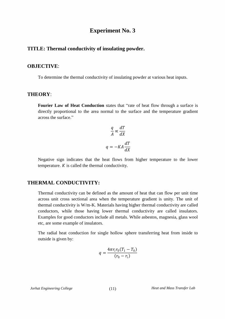
Experiment No. 3
TITLE: Thermal conductivity of insulating powder.
OBJECTIVE:
To determine the thermal conductivity of insulating powder at various heat inputs.
THEORY:
Fourier Law of Heat Conduction states that “rate of heat flow through a surface is
directly proportional to the area normal to the surface and the temperature gradient
across the surface.”
𝑞
𝐴∝
𝑑𝑇
𝑑𝑋
𝑞 = −𝐾𝐴𝑑𝑇
𝑑𝑋
Negative sign indicates that the heat flows from higher temperature to the lower
temperature. 𝐾 is called the thermal conductivity.
THERMAL CONDUCTIVITY:
Thermal conductivity can be defined as the amount of heat that can flow per unit time
across unit cross sectional area when the temperature gradient is unity. The unit of
thermal conductivity is W/m-K. Materials having higher thermal conductivity are called
conductors, while those having lower thermal conductivity are called insulators.
Examples for good conductors include all metals. While asbestos, magnesia, glass wool
etc, are some example of insulators.
The radial heat conduction for single hollow sphere transferring heat from inside to
outside is given by:
𝑞 =4𝜋𝑟𝑖𝑟0 𝑇1 − 𝑇0
𝑟0 − 𝑟𝑖

(12)
Jorhat Engineering College Heat and Mass Transfer Lab
Where,
𝑞 = Rate of heat transfer in watts
𝐾 = Thermal conductivity, w/m-K
𝑟𝑖 = Radius of inner sphere in meters
𝑟0 = Radius of outer sphere in meters
𝑇𝑖 = Temperature of the inner sphere
𝑇0 = Temperature of the outer sphere
DESCRIPTION:
The apparatus consists of two concentric copper spheres. Heating coil is provided in the
inner sphere. The space between the inner and outer spheres are filled by the insulating
powder whose thermal conductivity is to be determined. The power supply to the
heating coil is adjusted by using variac. Chromel-Alumel thermocouples are used to
record the temperatures. Thermocouples 1 to 6 are embedded on the surface of inner
sphere and 7 to 12 are embedded on the outer shell surface.
SPECIFICATION:
Radius of inner sphere = 100 mm
Radius of outer sphere = 200 mm
Voltmeter = 0-300 V
Ammeter = 0-5 amp
Variac = 2 Amps
Temperature Indicator = 0 – 300 0 C
PRECAUTIONS: Keep variac to zero volt position before switching “on” the unit and after
the experiment.

(13)
Jorhat Engineering College Heat and Mass Transfer Lab
PROCEDURE:
1. Connect the unit to an AC source 240 V, 5 Amp and switch on the MCB.
2. Operate the variac slowly to increase the heat input to the heater and adjust the
voltage to any desire voltage ( do not exceed 150 V)
3. Maintain the same heat input throughout the experiment until the temperatures
reaches a steady state.
4. Note down the following readings provided to the observation table.

(14)
Jorhat Engineering College Heat and Mass Transfer Lab
OBSERVATION TABLE:
Heat Input Inner Surface Temperature
℃ Outer Surface Temperature
℃
Time
(min)
V
(volt)
A
(Amp) Watt T1 T2 T3 T4 T5 T6 T7 T8 T9 T10 T11 T12

(15)
Jorhat Engineering College Heat and Mass Transfer Lab
CALCULATION:
(16)
Jorhat Engineering College Heat and Mass Transfer Lab
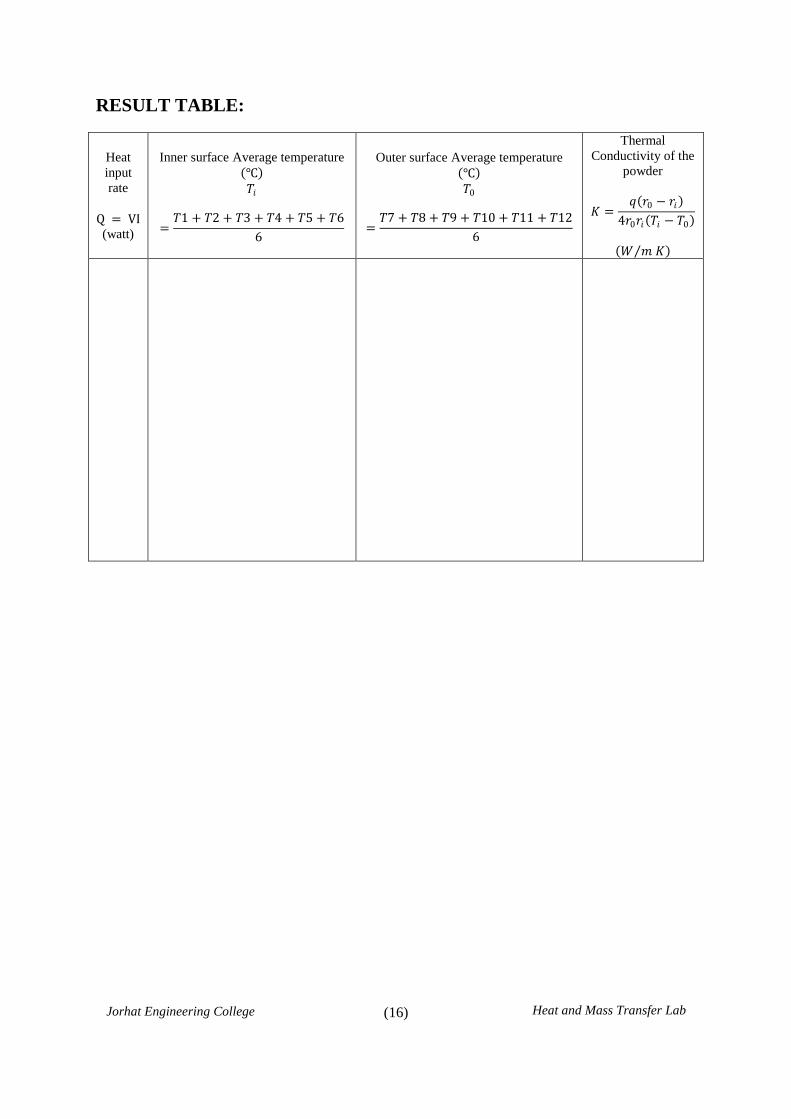
RESULT TABLE:
Heat
input
rate
Q = VI (watt)
Inner surface Average temperature
℃
𝑇𝑖
=𝑇1 + 𝑇2 + 𝑇3 + 𝑇4 + 𝑇5 + 𝑇6
6
Outer surface Average temperature
℃
𝑇0
=𝑇7 + 𝑇8 + 𝑇9 + 𝑇10 + 𝑇11 + 𝑇12
6
Thermal
Conductivity of the
powder
𝐾 =𝑞 𝑟0 − 𝑟𝑖
4𝑟0𝑟𝑖 𝑇𝑖 − 𝑇0
𝑊 𝑚 𝐾

(17)
Jorhat Engineering College Heat and Mass Transfer Lab
Exp. No. 3 Title: Thermal conductivity of insulating powder.
Name of Student:
Roll No.:
Date of Experiment:
Date of Submission:
Signature of Teacher SEAL
with Date of Check

(18)
Jorhat Engineering College Heat and Mass Transfer Lab
Experiment No. 4
Title: Heat transfer in natural convection.
OBJECTIVE:
1. To determine the convective heat transfer co-efficient for heated vertical cylinder
losing heat to the ambient by free or natural convection
2. To find the theoretical convective heat transfer coefficient and to compare with the
experimental value.
THEORY:
Convection heat transfer occurs by the movement of fluid particles. If the motion of
fluid particles occurs by the variation of density of the fluid due to temperature
difference, then the heat transfer process is called free or natural convection
The rate of heat transfer in convection is given by the Newton’s law of cooling i.e.
𝑄 = 𝐴 ∆𝑇
Where,
𝑄 = Heat transfer in 𝑤
𝐴 = Area of the tube.
∆𝑇 = Change in temperature.
𝐻 = Convective or film heat transfer coefficient, h depends upon the fluid
properties, type of flow and geometry of the surface.
DIMENSIONLESS NUMBERS:
Nusselt Number:
𝑁𝑢 =𝐿
𝐾=
𝐿 𝐾
1
𝑁𝑢 =Conductive resistance
Convective resistance=
Heat transfer by convection
Heat transfer by conduction
A larger value of 𝑁𝑢 implies enhanced heat transfer by convection.

(19)
Jorhat Engineering College Heat and Mass Transfer Lab
Prandtl Number:
𝑃𝑟 =𝜈
𝛼=
Viscous Diffusion Rate
Thermal Diffusion Rate=
𝜇𝐶𝑝
𝐾
This number represents the relative importance of momentum and energy transfer
by diffusion process.
Grashof Number:
𝐺𝑅 =𝐿3𝛽𝑔Δ𝑇
𝜈2=
Inertia force Buoyant force
Viscous force 2
Grashof number has an important role in free convection problems.
From dimensional analysis as per the Buckingham p1 theorem, a general relationship
between the above dimensionless numbers has been developed as given below:
𝑵𝒖 = 𝑪 𝑮𝒓𝑷𝒓 𝒎 , where 𝑚 and 𝐶 are constants
Experimental convective heat transfer coefficient,
𝑒𝑥𝑝 = 𝑞 𝐴 𝑇𝑠 − 𝑇𝛼
Where,
𝑞 = Heat Input
𝑇𝑠 = Surface Temperature
𝑇𝛼 = Ambient Temperature
𝐴 = 𝜋𝑑𝐿 = Surface area of the pipe
Theoretical convective heat transfer coefficient,
𝑡𝑒𝑜 = 𝑁𝑢𝐾 𝑑
𝑁𝑢 = 0.59 𝐺𝑟𝑃𝑟 0.25
𝐺𝑟𝑃𝑟 =𝐿3𝛽𝑔∆𝑇𝑃𝑟
𝜈2

(20)
Jorhat Engineering College Heat and Mass Transfer Lab
DESCRIPTION OF THE APPARATUS:
The apparatus consists of a vertical stainless steel tube enclosed in a rectangular duct;
front side of the duct is made of transparent section to facilitate visual observation. An
electrical heating element embedded in a copper tube acts as the heat source. The
surface temperature is measured at different heights using thermocouples. The surface
of the tube is polished to minimize radiation losses. A voltmeter and an ammeter enable
the determination of wattage dissipated by the heater. The chamber temperature can
also be measured.
SPECIFICATION:
Diameter of the Tube = 45 mm
Length of the Tube = 500 mm
PROCEDURE:
1. Connect the equipment to power supply. Set the voltmeter reading to some value say
50 V by using the dimmerstat and maintain it constant.
2. Allow sufficient time for obtaining steady state conditions.
3. After Steady state is reached note down the temperature T1 to T7 from the indicator
by operating the temperature selector switch.
4. Note down the Ambient temperature
5. Repeat the experiment for different heat inputs

(21)
Jorhat Engineering College Heat and Mass Transfer Lab
OBSERVATION TABLE:
Time
(min)
V
(volt)
I
(amp)
W
(watt)
Temperatures on the surface of the
pipe 𝑇𝑎𝑣𝑔
𝑇𝑠
Ambient
temperature
𝑇𝛼 T1 T2 T3 T4 T5 T6 T7

(22)
Jorhat Engineering College Heat and Mass Transfer Lab
CALCULATION:

(23)
Jorhat Engineering College Heat and Mass Transfer Lab
RESULT TABLE:
Film temp
𝑇𝑓
= 𝑇𝑠 + 𝑇𝛼 2
Properties of air (from tables) at 𝑇𝑓
GrPr Nu htheo hexp %
variation 𝜈
m2 sec Pr
𝐾
W mK 𝛽 = 1 𝑇𝑓
Exp. No. 4 Title: Heat transfer in natural convection.
Name of Student:
Roll No.:
Date of Experiment:
Date of Submission:
Signature of Teacher SEAL
with Date of Check

(24)
Jorhat Engineering College Heat and Mass Transfer Lab
Experiment No. 5
TITLE: Critical Heat Flux Apparatus.
OBJECTIVE:
To study the formation of bubbles under pool boiling process and calculate the value of
critical heat flux.
THEORY:
Boiling Heat Transfer Phenomena:
In general boiling is a convection process involving a change in phase from
liquid to vapour. Boiling may occur when a liquid is in contact with a surface
maintained at a temperature higher than the saturation temperature of the liquid.
Pool Boiling:
If heat is added to a liquid from a submerged solid surface, the boiling
process is referred to as pool boiling. In this process the vapour produced may
form bubbles, which grows and subsequently detach them from the surface, rising
to the free surface due to buoyancy effects.
Regimes of Pool Boiling (for Water):
Figure 5.1: Regimes of Pool Boiling

(25)
Jorhat Engineering College Heat and Mass Transfer Lab
1. Free convection zone: In region I, called the free convection zone, the excess
temperature T is very small considering here the liquid near the surface is
superheated slightly, the convection currents circulate the liquid and
evaporation takes place at liquid surface
2. Nucleate Boiling: This exists in regions II. As the excess temperature T is
created, bubbles begin to form on the surface of the wire at certain localized
spots. The bubbles condense in the liquid without reaching the liquid surface.
Region II represents the beginning of nucleate boiling. With the increase in
excess temperature, bubbles are formed more rapidly and rise to the surface of
the liquid resulting in rapid evaporation. The maximum heat flux, known as
critical heat flux occurs at point C& is about 1 MW/m2.
3. Transition Boiling: In this region the heat flux decreases. This is because a
large fraction of the heater surface is covered by a vapour film, which acts as
an insulation due to the low thermal conductivity of the vapour relative to that
of the liquid. In transition boiling regime, both nucleate and film boiling
partially occur. Nucleate boiling t point C is completely replaced by film
boiling at point D.
4. Film Boiling Region: In this region the heater surface is completely covered
by a continuous stable vapour film. The heat transfer rate increases with
increasing excess temperature as a result of heat transfer from the heated
surface to the liquid through the vapour film by radiation, which becomes
significant at high temperatures.
The stable boiling phenomenon can be observed when a drop of water falls
on a red hot stove. The drop does not evaporate immediately but dances a few
times on the stove. This is due to the formation of a stable steam film at the
interface between the hot surface and the liquid droplet. This observation was
first made by J. C. Leidenfrost and thus the point D, where the heat flux reaches a
minimum is called the Leidenfrost point in his honour.
SPECIFICATONS:
Length of the nichrome wire = 40 mm
Diameter of the nichrome wire = 0.25 mm (33 gauge)

(26)
Jorhat Engineering College Heat and Mass Transfer Lab
PROCEDURE:
1. Connect the nichrome test wire to heat terminals & place it in the container having
distilled water.
2. Switch on the main heater and heat the water to the desired temperature (700C) and
then switch off the main heater.
3. Now switch on the test heater. Gradually increase the voltage across the test heater by
using the Variac. Continue this till the wire breaks down.
4. Calculate the value of the critical heat flux using the value of current and voltage
obtained at burnout.
OBSERVATION TABLE:
Sl.
No.
Voltage
(𝑉)
Current
(𝐼)
Heat input
𝑞 = 𝑉 × 𝐼
Value of Critical
Heat Flux
𝑀𝑊 𝑚2
CALCULATION:

(27)
Jorhat Engineering College Heat and Mass Transfer Lab
Exp. No. 5 Title: Critical Heat Flux Apparatus.
Name of Student:
Roll No.:
Date of Experiment:
Date of Submission:
Signature of Teacher SEAL
with Date of Check

(28)
Jorhat Engineering College Heat and Mass Transfer Lab
Experiment No. 6
TITLE: Heat Transfer through Lagged Pipe Apparatus.
OBJECTIVE:
Plot the radial temperature distribution in the composite cylinder and determine the
thermal conductivity of the pipe insulation.
THEORY:
Consider one dimensional radial heat flow through a hollow cylinder, under steady state
conditions:
𝑞 = 2𝜋𝐾𝐿 𝑇1 − 𝑇2
ln𝑟2𝑟1
Where,
T1 & T2 = Inner and Outer Wall Temperature.
r1 and r2 = The Inner and Outer Radii of the Pipe.
K = Thermal conductivity of the material.
DESCRIPTION OF THE APPARATUS:
The apparatus consists of a metal pipe with two layers of insulation. An electric
heating coil wound on a silica rod is placed at the centre. The ends are thickly insulated
to prevent heat loss so that, heat can flow only in a radial direction. Three
thermocouples each are placed at different radii to measure the temperature distribution
within the cylinder.
SPECIFICATONS:
1. Location of thermocouples 1,2,3 at radius = 30mm
2. Location of thermocouples 4,5,6 at radius = 52mm
3. Location of thermocouples 7,8,9 at radius = 55mm
4. Length of Pipe = 500mm
(29)
Jorhat Engineering College Heat and Mass Transfer Lab
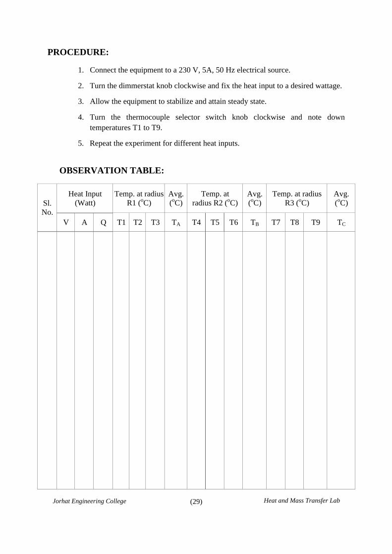
PROCEDURE:
1. Connect the equipment to a 230 V, 5A, 50 Hz electrical source.
2. Turn the dimmerstat knob clockwise and fix the heat input to a desired wattage.
3. Allow the equipment to stabilize and attain steady state.
4. Turn the thermocouple selector switch knob clockwise and note down
temperatures T1 to T9.
5. Repeat the experiment for different heat inputs.
OBSERVATION TABLE:
Sl.
No.
Heat Input
(Watt)
Temp. at radius
R1 (oC)
Avg.
(oC)
Temp. at
radius R2 (oC)
Avg.
(oC)
Temp. at radius
R3 (oC)
Avg.
(oC)
V A Q T1 T2 T3 TA T4 T5 T6 TB T7 T8 T9 TC
(30)
Jorhat Engineering College Heat and Mass Transfer Lab
CALCULATION:
1. Plot the temperature vs. radius to get radial temperature distribution.

(31)
Jorhat Engineering College Heat and Mass Transfer Lab
2. Find the conductivity of the insulation.

(32)
Jorhat Engineering College Heat and Mass Transfer Lab
Exp. No. 6 Title: Heat Transfer through Lagged Pipe Apparatus.
Name of Student:
Roll No.:
Date of Experiment:
Date of Submission:
Signature of Teacher SEAL
with Date of Check


![3 ليلحتلا...][Maths_WhatsApp : 0991921144 Facebook_Page : IOM F.B Group : Syria Math – 2nd Year 2 𝑓 𝑥 𝜀 𝑓 𝑥 𝑓 𝑥 𝜀 حتزامري îكذ أ ñز íس](https://static.fdocuments.net/doc/165x107/5eb50407258fcd2ae7579525/3-mathswhatsapp-0991921144-facebookpage-iom-fb-group.jpg)


