
health physics manual of good practices for accelerator facilities
140
SLAC–327 UC-41 (A) HEALTH PHYSICS MANUAL OF GOOD PRACTICES FOR ACCELERATOR FACILITIES W. R. CASEY, BNL A. J. MILLER, LANL J. B. MCCASLIN, LBL L. V. COULSON, FNAL Advisors: K. F. CROOK, SLAC T. N. SIMMON, SNL R. C. MCCALL, SLAC, CHAIRMAN E. J. VALLARIO, D O E PROJECT MANAGER Stanford Linear Accelerator Center Stanford University, Stanford, CA 94309 April 1988 Prepared for the U.S. Department of Energy Assistant Secretary for Environment, Safety, and Health under Contract DE-A C03-76SFO0515. Printed in the United States of America. Available from the National Technical Information Service, U. S. Dep=tment of Commerce, 5285 Port Royal Road, Springfield, VA 22161. Price: Printed Copy A07, Microfiche AO1.
Transcript of health physics manual of good practices for accelerator facilities

SLAC–327
UC-41
(A)
HEALTH PHYSICS MANUAL OF GOOD
PRACTICES FOR ACCELERATOR FACILITIES
W. R. CASEY, BNL
A. J. MILLER, LANL
J. B. MCCASLIN, LBL
L. V. COULSON, FNAL
Advisors:
K. F. CROOK, SLAC
T. N. SIMMON, SNL
R. C. MCCALL, SLAC, CHAIRMAN
E. J. VALLARIO, D O E PROJECT MANAGER
Stanford Linear Accelerator Center
Stanford University, Stanford, CA 94309
April 1988
Prepared for the U.S. Department of Energy Assistant Secretary for
Environment, Safety, and Health under Contract DE-A C03-76SFO0515.
Printed in the United States of America. Available from the National Technical Information
Service, U. S. Dep=tment of Commerce, 5285 Port Royal Road, Springfield, VA 22161. Price:
Printed Copy A07, Microfiche AO1.

w.
ACKNOWLEDGEMENTS
Important contributions to the text were made by W. Freeman, T. Jenkins,
Swanson, and M. Howe. Technical editing was performed by Roberta Fried- -
man. Assistance in computer processing the text w= obtained from W. Nelson,
D. Gelphman, and B. Kempton. Many days of patient and skillful secretarial
work were done by D. Lacey. The Committee gratefully acknowledges the help
of all of the people listed above.
-.
ii
FOREWORD
The Department of Energy’s (DOE) Office of Nuclear Safety (ONS), Health
Physics Branch, has, in coordination with principals at many of the DOE labora-
tories, identified the need to develop four priority facility guides of good practice.
These include radiological safety guidance for accelerator, plutonium, tritium,
and uranium facilities.
This manual presents guidance to be used to develop and conduct radiation
protection programs at DOE accelerator facilities. The guidance w= prepared
by a carefully selected cadre of expert accelerator health physicists representing
the experience of six major accelerator sites, i.e., (1) Stanford Linear Accelerator
Center (SLAC), (2) Brookhaven National Laboratory (BNL), (3) Fermi National -–
Accelerator Laboratory (Fermilab), (4) Lawrence Berkeley Laboratory (LBL),
(5) Los Alamos National Laboratory (LANL), and (6) Sandia National Labora-
tories (SNL). The manual was subsequently reviewed by a peer review group of
accelerator health physicists throughout the Department’s program preparatory
of finalization and publication.
Unlike other facility categories, such as plutonium facilities, the diversity of
accelerator types, their size, design, and beam properties require varying strate-
gies for radiation safety. For example, proton accelerators, in contrast to electron
accelerators, exhibit different radiation characterist its, and hence me~urernent
control processes. The authors of this guide provided greater emphasis on the
unique characteristics from the radiological safety viewpoint of the various ac---
celerators and less stress on those radiation safety aspects which are common to
...111

all accelerators. It is hoped that this manual will serve both as a teaching aid m
well as a useful adjunct for program development. In the context of application,
this- manual addresses good practices that should be observed by management,
staff, and designers since the achievement of a good radiation program indeed
involves a combined effort. Ultimately, radiation safety and good work practices
become the personal responsibility of the individual.
The practices presented in this manual are not to be construed as mandatory
rather they are to be used w appropriate for the specific case in the interest of
radiation safety. As experience is accrued and new data obtained in the appli-
cation of this document, ONS will update the guidance to assure that at any
given time the guidance reflects optimum performance consistent with current
technology and practice.
~q .. “ ~-–-E ard J. Va arlo
tActing Dire/ orRadiological Controls Division
Office of Nl~clear Safety
--
iv
TABLE OF CONTENTS
1. INTRODUCTION . . . . . . . . . . . . .
1.1 Applicability of this Report . . . . . .
1.2 Small versus Large Facilities . . . . . .
2 ACCELERATOR FACILITY DESIGN . . .
2.1 Criteria for Siting Accelerator Facilities
2.2 High Energy Interactions (Source Terms)
2.3 Other Radiation Sources . . . . . . . .
2.4 Shielding Design . . . . . . . . . . . .
2.5 Interlock and Warning Devices . . . . .
2.6 Beam Containment . . . . . . . . . . .
3. OPERATIONAL CONSIDERATIONS FOR
. . . . . . . . . . . . . . . 1
. . . . . . . . . . . . . . . 3-
. . . . . . . . . . . . . . . 4
. . . . . . . . . . . . . . . 5
. . . . . . . . . . . . . . . 5
. . . . . . . . . . . . . . 9
. . . . . . . . . . . . . . . 15
. . . . . . . . . . . . . . . 17
. . . . . . . . . . . . . . . 21
. . . . . . . . . . . . . . . 28
HEALTH PHYSICS . . . . 32
3.1
3.2
3.3
3.4
3.5
3.6
Control of Radioactivation and Contamination . . . . . . . . . . . 32
Radioactive W~te Management . . . . . . . . . . . . . . . . . . . 42
Radiation Damage to Components . . . . . . . . . . . . . . . . . . 44
Instruments and Measurements . . . . . . . . . . . . . . . . . . . 47 -
Personnel Dosimetry . . . . . . . . . . . . . . . . . . . . . . . . .61
Experimenter Access to Secondary Beams . . . . . . . . . . . . . . 64
4. ADMINISTRATION OF A HEALTH PHYSICS PROGRAM . . . . . . 65
4.1 Records . . . . . . . . . . . . . . . . . . . . . . . . . . . . . . ..65
4.2 Audits . . . . . . . . . . . . . . . . . . . . . . . . . . . . . . ..69
4.3 Written Procedures and Administrative Controls . . . . . . . . . . 71
4.4 Radiation- Safety Staff.... . . . . . . . . . . . . . . . . . . . . 76
5. DISMANTLING, DECONTAMINATION, AND DECOMMISSIONING 79
5.1 Facility Design . . . . . . . . . . . . . . . . . . . . . . . . . ...79
5.2 Facility Operations . . . . . . . . . . . . . . . . . . . . . . . ...80
5.3 Planning Dismantling and Decommissioning . . . . . . . . . . . . . 81
5.4 Dismantling and Decommissioning Operations . . . . . . . . . . . . 82
5.5 Operations After Dismantling and Decommissioning . . . . . . . . . 84
APPENDICES . . . . . . . . . . . . . . . . . . . . . . . . . . . . . . . . . 86
REFERENCES . . . . . . . . . . . . . . . . . . . . . . . . . . . . . . . . . . 111
INDEX . . . . . . . . . . . . . . . . . . . . . . . . . . . . . . . . . . . . 133
v
1.
Particle accelerators pose
INTRODUCTION
unique problems for health physics. The primary
particle beam can produce enormous dose rates of radiation over small areas. -
Moreover, the secondary radiation (bremsstrahlung, neutrons, scattered elec-
trons, and so forth) can create very high dose rates over large arem of the accel-
erator workplace. Some of the secondary radiation is quite penetrating. If the
primary energy is high enough, residual radioactivity can be produced.
Accelerators vary, and strategies for radiation safety must be tailored to the
beam properties of each. Prompt radiation, both primary and secondary, is often
produced in pulses. For some accelerators, the pulses may be a small fraction of
a second long and come at several hundred pulses per second. In other machines,
pulses a few seconds long are produced several times per minute. Great diversity
also exists in the kind of particle accelerated, the energy range, and method of
acceleration. Table I gives a partial list of DOE accelerators; it does not include —.
a number of smaller accelerators.
Radiation doses for personnel working at DOE accelerators have been rather
small and have decre~ed over the years (see Appendix A). The nature of accel-
erator radiation fields is such that while the potential for very high accidental
exposures exists, routine doses are small. This will become apparent in later
sections of this guide.
The amount of literature on the health physics of a given type of accelerator
is, in general, proportional to how many of that type are in use. The elec-
tron linacs used in radiation therapy (about 1100 in the United States) have
been well characterized, and the NCRP has published several guides to their
radiation safety problems (NCRP76, NCRP77, NCRP84). While therapy elec-
tron linacs and conventional x-ray machines are not discussed in the present
manual, some aspects covered in the NCRP reports may nevertheless apply
to the health physics of other accelerators. Then there are half a dozen or so--
1

TABLE I. DOE SEL~CTED LIST OF ACCELERATORS
Accelerator Laborato~ Ener~ Year of kitialField Office (GeV) Operation bteraction &pe
BNL AGS BNL/CH 33 1961 Proton Synchrotron
LLNL Linac I LLNL/SAN I 0.05 I 1970 I Electron Linac
Super Hflac LBL/SAN 0.0085** 1971 Positive Ion Linac
FermiMain Ring FNAL/CH 400 1972 Proton Synchrotron
Los Alamos Meson Physics Facfity (LAMPF) LANL/AL 0.8 1972 Positive Ion Linac
Ba;es MIT/CH 1.0 1972 Electron Linac
SPhAR SLAC/SAN 3.5x3.5 1972 (e+e-) CoUidingBeam
ktense Puked Neutron Source ANL/CH 0.5 1976 Proton Synchrotron
BEVALAC LBL/SAN 2.1** 1977 Positive Ion Synchrotron
PEP SLAC/SAN 15X15 1981 (e+e-) Colhding Beam
Hohfield Heavy Ion Facfity
Advanced Test Accelerator (ATA)
Fl=h X-Ray Accelerator (FXR)
National Synchrotron Light Source
ORNL/OR
LLNL/SAN
LLNL/SAN
BNL/CH
0.025 1982
0.05 I 1982
0.02 I 1982
0.75 Vuv 1983
2.5 1983
Heavy Ion/TandemVan de Graafi
Electron Linac
Electron Linac
VUV Ringx–Ray Ring
ATLAS ANL/CH 0.025 1986 Positive Ion Linac
Stanford LinearCoWder (SLC) SLAC/SAN 50X50 1986 (e+e–) Cofiding Beam
Tevatron I FNAL/CH 1000X1OOO 1987 (pp) CoMding Beam
Tevatron II FNAL/CH 1000 1986 Proton Synchrotron
Particle Beam FusionAccelerator (PBFA 11) SNLA/AL 30 1986 Lithium Ion Linac Array
HermesIII SNLA/AL 0.02 1986 Electron Linac x–Ray
CEBAF SURA/CH 4 1990*** Electron Linac
SuperconductingSuper Collider Not Selected 20,000X20,000 1990*** (pp) Colliding Beam
*Not including lower energy van de Graffs, dynamitrons, neutron generators, and university operated accelerators.**Per nucleon.
t
***b planning or constructionstage.r

high energy wcelerators that operate above 1 GeV. A greater range of physics
comes into play in the health physics of these machines, which are more likely to
be modified and used for different purposes than are small accelerators. Except
for one book (Pa73), and two book size IAEA reports (IAEA79, IAEA89) most
of the literature for the health physics of these large machines is in the form of
journal articles or reports.
The intent of this guide therefore is to:
●
●
●
●
●
Define common health physics problems at accelerators.
Recommend suitable methods of identifying, evaluating, and managing ac-
celerator health physics problems.
Set out the established safety practices at DOE =celerators that have been
arrived at by consensus and, where consensus has not yet been reached, give
examples of safe practices.
Introduce the technical literature in the accelerator health physics field.
Supplement the regulatory documents listed in Appendix D.
Many accelerator health physics problems are no different than those at other
kinds of facilities, e.g., ALARA philosophy (D OE80, ICRP82, NCRP87), instru-
ment calibration, etc. These problems are touched on very lightly or not at all.
Similarly, this document does not cover other hazards such as electrical shock,
toxic materials, etc. This does not in any way imply that these problems are not
serious.
1.1 APPLICABILITY OF THIS REPORT
Some portions of this report are less broadly applicable than others; such
sections will be indicated. Moreover, safety solutions and suggestions given here
are not necessarily unique. The responsible health physicist must be alert to
other options offering equal or better safety under particular circumstances of--
management, hardware, or staffing. This document should thus be viewed as a
3

guide to selecting safety me=ures that will give adequate radiation protection.
There will always be exceptions, and the responsible health physicist will some-
times have to decide that certain recommendations made here cannot be applied
at his or her facility. Any exceptions and the reasons for them be must be care-
fully considered. Such exceptions should be reviewed periodically, and when the
accelerator or its mode of operation are changed, to check that the re~ons for
the exceptions are still valid.
1.2 SMALL VERSUS LARGE FACILITIES
Many different kinds of accelerator facilities exist within programs sponsored
by the DOE. The tasks performed vary considerably, ranging from studies per-
formed in a simple, one-room setting to those conducted in multiple buildings
spread over many square miles.
Keeping size differences in mind, certain points should be made about the _
safety guidelines set forth here. Most important is to understand that any ac-
celerator creates a substantial hazard. A small accelerator operating at 3 MeV
can produce levels of radiation just as dangerous as those from the highest en-
ergy machines. Thus, even for small accelerators, =cess control and many other
safety features should be as well designed and maintained w at bigger facilities.
Usually, though, smaller facilities mean simpler control systems. With less
staff to coordinate, smaller arem to monitor, and fewer points of access to control,
the radiation safety program will be simpler. As an example, a small accelerator
may have a single health physicist who is also responsible for other areas. The
health physicist periodically visits each facility to monitor activities in progress,
review records, discuss coming activities, and provide other services that may be
needed. In such cases, it is important to set approved limits to the operation
of the accelerator. To operate beyond these limits would then require prior
review with the health physicist, to determine whether additional safeguards or--
monitoring are necessary.
4

Another potential pitfall of the simpler organization at small facilities is when
someone is designated M Radiation Safety Officer (RSO) who may have no for-
mal training in health physics. Frequently this person may be a scientist or
operator at the facility who is assigned the duties of RSO in addition to his or
her other responsibilities. This arrangement can work safely if the RSO is cho-
sen to have minimum conflicts of interest. However, there must be a periodic,
professional overview of the health physics program and a clear definition of the
approved bounds within which the accelerator has been shown to operate safely.
In addition, when the RSO carries multiple responsibilities, management must
be particularly vigilant that safety not be compromised by operating pressures.
In all cases, internal audits should be performed (see Section 4.2).
In contr=t to smaller facilities, a large accelerator will usually employ sev-
eral professional health physicists and technicians whose only duties concern the
safety at that accelerator. Still, the distinction between small and large facilities
is gradual, not sharp. Smaller size may permit a reduced scale for the radiation -—
safety program, but it never justifies poorly-defined or carelessly-implemented
safety measures.
2. ACCELERATOR FACILITY DESIGNS
2.1 CRI.TERIA FOR SITING ACCELERATOR FA CILITIES
Setting criteria for radiation protection in advance of site selection can sim-
plify finding and selecting a satisfactory site for an accelerator. If a site is chosen
which closely matches well-thought-out design criteria, delays for redesign and
costly retrofits can be avoided.
Although one can develop siting criteria after the accelerator and its facilities
are designed, it is often more efficient and economical, especially for large projects,
to develop the criteria in parallel with the design. This can provide prompt--
feedback to designers on the safety impact of design features.
5
Once the primary accelerator parameters such as energy, kinds of particles,
and power are decided, determining the siting criteria requires cooperation among
personnel. Participants should be familiar with the facility’s design, and with
radiation physics and safety regulations. It is invaluable to have persons on the
team, or at least available for consultation, who have had working experience in
all these are=.
Knowing the magnitude of the radiation source and the allowable radiation
levels makes it possible to design appropriate protection into the facility. The
starting point is to list design parameters for the accelerator. Design parame-
ters can then be combined with assumptions about the expected operation and
be used to estimate radiation levels. Restrictions on radiation levels, set from
appropriate standards, can then be used to develop the facility’s design. The
resulting criteria would thus specify shielding walls, berms, distances, and other
features of the site required to accommodate the me~ures necessary for radiation
protection.
Recommendations for Setting Site Criteria
The larger or more complicated the accelerator design, the more effort will
be needed to decide siting criteria. The general procedures recommended here
can be scaled up or down to fit the need.
The accelerator’s design parameters completely determine the nature and
magnitude of the radiation source. The most important parameters are: kind
of particle accelerated, particle energy, beam power, target material, and work
load.
A wide variety of techniques are available to estimate radiation levels. These
techniques range from very sophisticated Monte Carlo computer programs or
direct analytic expressions, to “rules of thumb” and published and unpublished
experimental me=urements. Details of these methods will be discussed below.
In addition, guida~ce is available from radiation physics personnel at any of the
6
major DOE accelerator laboratories.
A full listing of all potential radiation problems which should be analyzed is
not -attempted here. Following are some of the most important and less obvious
ones.
Prompt-Direct Radiation: Numerous computer codes and mathematical mod-
els have been developed which can predict the amount of direct, prompt radiation
(neutrons, photons, muons, and so forth) which will contribute to off-site dose.
Both normal operating conditions and conditions of abnormal beam loss should
be considered. Section 2.2 of this guide introduces the most common, relevant
techniques to calculate prompt radiation.
Skyshine: Historically, a common weak point in accelerator design has been
thin “roo~ shielding. As a result, skyshine (air scattered) neutrons commonly
contribute significantly to the radiation dose in uncontrolled areas. Me~ure-
ments (C085, Ri75, St84) have verified that mathematical models (Je74, Pa73,-–
Ri75) are adequate to calculate doses of neutron skyshine out to about 1200 feet.
However, at distances of half a mile or more, the various models may disagree
by at lewt an order of magnitude. At large distances, dose rates are simply too ~
low to measure with any degree of accuracy. Deliberately increasing the source
strength to allow such memurements is probably not justified, in view of the dose
that would result to the general population and the trivial level of the normal
skyshine dose (Je74).
It is required to report the annual general population dose (person-rem within
a 5&mile radius). Here the choice of model can affect calculated results consid-
erably. For consistency, the methods and constants given in St84 should be used
to calculate annual population dose.
Photon skyshine is usually less of a problem but should be considered, espe-
cially for are= where radioactive material is stored. Again, there are models for
calculating this component of the environmental radiation dose (Bi69; B075).
7

Activation: Estimates of the off-site dose from airborne radioactivity should
be made. Air activation is most significant in are= of routine, high intensity
beam losses such as near beam dumps, targets, or collimators.
Radioactive Water: Routine discharges and spills of radioactive water should
also be considered. Common sources of radioactive water are the closed loops
containing water used to cool magnets, targets, and beam dumps. However, one
should also consider the water that is collected in sumps and then discharged to
the environment.
For some accelerators, activation of soil and ground water outside the shield-
ing may also be relevant. Ground water that is either directly exposed to the
prompt radiation, or passes through soil that h= been activated, may transport
radionuclides to an underground aquifer or to surface water.
Information from state or local hydrologists and geologists on annual rainfall,
the nature of the site’s geology, and velocity of the area’s subsurface water can -—
be used to predict the concentrations at which isotopes would begin to leach into
drinking water (CEBAF87, G078).
Storage and Transportation: Storage and transportation of activated accel-
erator components can contribute significantly to the annual site boundary dose.
By estimating the amount and nature of radioactive material to be stored, one
can estimate ‘the site boundary dose due to both direct radiation and photon
skyshine. Other contributions to site boundary dose are the shops or labs where
radioactive items are repaired or maintained. Judicious locations of storage are=,
shops, and labs will help minimize the site boundary dose.
Radiation Protection Standards: DOE Orders define minimum standards for
radiation protection. However, state and local requirements for environmental
protection are often more restrictive than federal ones, and may prevail off-site.
It is recommended that, early in design, concurrence of the DOE be sought on
all applicable radi~tion limits. (See Appendix D.)
8
Facility Design: Once the radiation source terms and applicable radiation
limits have been determined, the necessary radiation protection measures can
be designed. For accelerators, this most often means shielding the sources with
concrete, steel, or earth. However, the use of distance, interlocks, barriers, and
even restriction of operations should be considered.
Accident Considerations: Rarely do thoughts of possible accidents affect sit-
ing designs for accelerators.
2.2 HIGH ENERGY
Particle accelerators are
Yet accidents should be considered (E186).
INTERACTIONS (SOURCE TERMS)
designed for a variety of purposes, such as research
into the nature of matter, production of radioisotopes, generation of bremsstrahlung
for radiography, induction of fusion, pumping of l=ers, and production of syn-
chrotron radiation. Each purpose dictates a particular energy range and choice
of particle to be accelerated—electrons, protons, or nuclei of heavier elements. -—
For a particular primary beam, then, the health physicist has to understand the
radiation fields produced - the beam is absorbed, since the resultant dose rates
can be quite high.
Proton Accelerators
If the accelerated particle is a proton, the physics of the interaction can be
discussed in the following energy domains.
● Elastic Interaction Region: In this energy domain, the proton interacts only
by elastic scattering. For most target materials, proton energies in excess
of 6 to 8 MeV will be required to exceed the inelastic threshold, though in
certain materials (for example, protons on tritium) reactions can take place
at very low energies. The range of protons with energies less than 8 MeV
is quite limited; it is less than 1 mm in most solid materials and less than--
1 m in air.
9
For the most part, the Radiation Safety Officer for proton machines oper-
ating in this low energy range will need only to prevent direct exposure to
the primary beam.
● Inelastic Interaction Region: If the incident particle has enough energy to
penetrate the coulomb barrier, that energy can be transferred to the nuclei
of the target, which will emit neutrons and other nuclear fragments. This
transfer is cl=sified = an inel~tic process. For energies up to about 100
MeV, the dominant inel~tic process is the isotropic emission of neutrons
from the target nucleus. These evaporation neutrons have energies up to
about 20 MeV, depending on the energy of the primary particle.
The dose rates produced by evaporation neutrons can be quite high. The
need to attenuate them dominates shielding requirements for this energy
range.
● Particle Production Region: In addition to evaporation neutrons, neutrons —.
and protons will also be emitted in the forward direction, at energies which
can be a significant fraction of the incident particles’ energy. These are
called cucade neutrons and protons since they are part of the cascade ~
started by an incident particle. In the c=cade, energy is transferred or lost
to the target materials if the incident particle’s energy is high enough. And
u the energy of the incident particle increases, the emission angle of the
c~cade particles becomes more and more peaked in the forward direction.
When the energy of the incident proton exceeds about 140 MeV, pions and
other particles can be produced, which must also be managed.
Because so many particles are produced in the forward direction, shield-
ing must be much more extensive along the beam direction. For example,
muons produced by the decay of pions in flight are very penetrating, espe-
cially at energies greater than a few GeV. Yet these muons are quite forward
peaked, so they do not enter into considerations for the shielding needed--
at wide angles. As accelerator energies incre~e, muons become important
10
at increuingly wide angles, however.
Electron Accelerators
If the incident particle is an electron, the physics of the interactions can be
discussed in the following energy domains.
Low Energy (<6 MeV): Below 6 to 10 MeV, electrons lose energy only
by ionization and bremsstrahlung (x-rays) production in most target ma-
terials (beryllium and deuterium are exceptions). For electron machines
that operate in this energy region, the primary electron beam and the
photons it produces must be shielded. The bremsstrahlung becomes for-
ward peaked in intensity when the electron energy is more than about 2
MeV. Backscattered electrons can also produce significant doses of radia-
tion within shielded enclosures.
Giant Resonance Region (6 to 50 MeV): In the energy region between 6 and -
about 50 MeV, energy can be transferred to the nucleus by photons prw
duced along the electron’s track, leaving the nucleus in an excited state with
the subsequent boil-off of a neutron. Bremsstrahlung is still the predomi-
nant source of radiation that shielding must deal with, but the presence of
neutrons usually dictates use of a hydrogenous shielding material such as
concrete.
The bremsstrahlung is incre~ingly forward peaked u the electron energy
increases, where= giant resonance neutrons are produced nearly isotrop-
ically. For exposures inside the shield, electrons may be a major factor,
depending upon the primary electrons’ energy, and the target configura-
tion.
Intermediate Energy Region (30 to 150 MeV): In this energy region, neu-
trons are produced by the pseudodeuteron process. The production cross--
section for this process is lower than that for giant resonance and bremsstrahlung
11

●
still dominates shielding considerations. However, the energy of the neu-
trons is increasing, and their removal cross section is smaller. For exposures
inside the shield, electrons, and bremsstrahlung will be the major comp~
nents of the dose.
High Energy Region (above 150 MeV): Above the threshold for pion pro
duction, neutrons can be produced with energies up to nearly the energy
of the primary particle. These neutrons are very penetrating, and in fact
determine the required thickness of concrete shields greater than about 120
cm. While these high energy neutrons are forward peaked, they still are
the most important consideration for thick transverse shields. For exp~
sures inside the shield, bremsstrahlung will
radiation dose. However, the exact nature
increasingly dependent on particle energy,
usually be the major source of
of the radiation field becomes
the target’s configuration and
material, and the relative position of the target and the subject.
In this energy range, muons also can be produced by direct pair produc-
tion = well as by pion decay. These muons are important contributors to
radiation in the forward direction (IAEA79).
Heavy Ion Accelerators
Experience k shown that neutrons dominate the radiation field outside of
the shielding of heavy ion accelerators at energies above the coulomb barrier.
With light ions of several hundred MeV per nucleon and thin shields or at for-
ward angles to the beam direction the dose equivalent outside the shield may be
dominated by neutrons of energy greater than 20 MeV. Unlike protons, there does
not exist a large body of experimental source term data. Hubbard et al. (Hu60)
me=ured global neutron yields from carbon, and nitrogen and neon beams at
10.4 MeV.A (MeV per ion, A is the atomic m~s number) on several target ele-
ments. Ohnesorge et al. (Oh80) me=ured neutron dose equivalent rates at 90°--
near medium-m~s targets for carbon, nitrogen, oxygen, and neon beams of 3
12
-—

MeV.A to 16 MeV.A. Greenhouse et al. (Gr87) used a Bonner sphere neutron
spectrometer to measure the energy spectrum of neutrons outside of a concrete
shield for 8.5 MeV”A argon ions on a thick copper target.
Other experimental data are cited and briefly summarized by Clapier and
Zoidins (C183) who present analytical expressions for the unscattered neutron
fluence and dose equivalent rates from unshielded thick targets. The fit to the
sparse experimental data m a function of incident nucleon energy and atomic
number is within a factor of two for beam ion energies of less than 15 MeV.A.
Me=urements of neutron yields and angular distributions were made by Mc-
Caslin et al. (Mc85) with 670 MeV.A neon and silicon ions on a thick copper
target. A rough measure of neutron spectra was obtained by using activation
detectors with energy thresholds from thermal energies to 50 MeV. Fluence at-
tenuation profiles through concrete were also determined.
For shielding design, the energy spectra of the reaction products are needed in _
addition to particle yields and angular distribution. Also, fluence or dose equiv-
alent attenuation profiles through the shielding are very useful. For example,
although the average nucleon energy was 10.4 MeV for the ion beams in Hub-
bard’s me~urements, the presence of neutrons of energy greater than 20 MeV
has been observed outside of the concrete shield by carbon activation memure-
ments, although at a significantly lower fluence rate than for the predominant
neutron energy group of about 1–3 MeV. In order to shield a low intensity beam
it may be acceptable, in absence of the full source term, to bme the calculation
on neutrons of the average nucleon energy of the beam ion. However, for a high
intensity beam which will require a much thicker shield, the neutrons of lower
energy will be attenuated in the first layers of the shield so that it will be the
high energy component which ultimately determines the overall shield thickness.
hitially, for low energy heavy ion beams, one must determine whether the
incident ion has sufficient energy to penetrate the coulomb barrier of the target--
atom and consequently to produce neutrons. For ions of mus greater than that
13

of protons, the energy below which only coulomb interactions can occur is given
by (A172)
(~B)Mw = ‘1Z2(1+*)A;+ A:+2
where 21 and 22 are the charge numbers of the beam particle and target nucleus,
respectively, and Al and A2 are their respective mass numbers.
The approximate relationship between charge and m~s number for stable
nuclei is given by (A172)
Z = 0.487A
()
1+ &166
.
-—Radiation Field Calculations
The calculation of numerical values for the radiation fields discussed above
is a topic too large for this manual, and the reader is referred to the literature
(IAEA79, IAEA89, ICRU78, Je79, NCRP77, NCRP84, Ne76, Ne80, Pa73, Ri73, ~
Te79). This list is a representative sampling but is by no means exhaustive.
Some useful computer codes for calculating source terms are EGS4, FLUKA82,
HETC, CASIM, and ITS (see Appendix E).
Residual Radioactivity
While not properly a source term, residual radioactivity may make up an
important part of the radiation field inside the shield. Whenever the electron
energy is greater than the binding energy of a nucleon, or when a proton can
penetrate the coulomb barrier, a residually radioactive nucleus may form. Resid-
ual radioactivity is not as great in electron machines as in proton machines, since
in the former, most of the primary energy goes into ionization and production of--
photons and electron-positron pairs.
14

Accelerators usedto produce isotopes present special problems becauseof
the wide variety oftarget materials used, and because the parameters ofmachine
and target are deliberately optimizedto produce radioactive isotopes.
2.3 OTHER RADIATION SOURCES
While the accelerator is the most obvious source of radiation at a facility,
there can be others, such as klystrons, experimental devices in other buildings,
or RF tests. These other sources can be much harder to control because the
health physicist may not know they exist, the way that the radiation is produced
may not be understood, or, the experimenter or user may not recognize that a
device produces radiation.
In general, whenever there is high voltage or RF power in a vacuum, x-rays
can be produced. This is true even though there is no heated filament or some
other obvious source of electrons. Since the physics is not well understood, some -.
anecdotal examples will show the severity of these radiation problems.
● The RF cavity for a storage ring was being tested. At 200 kW of RF power,
the x-ray dose at 1 meter was 500 mrad/hour (1.4 pGy/s). The dose W= ~
found to increase with the 5th power of the RF power. The highest planned
- power level was 350 kW which would have produced about 8 rad/hr (22
pGy/s) ..
. A secondary emission test device being operated at 110 kV dc produced
160 rad/hour (440 pGy/s) at 10 cm from a glass viewing post.
● A doubler RF cavity, with 65 kW of RF applied, produced about 5 rad/hr
14 ~Gy/s) at 1 foot (30 cm).
● h a test for a high gradient accelerator, high RF power w- applied to a 10
inch (25 cm) section of a standing wave accelerator that had no gun. With
35 MW of RF power and 120 pps (Hz), at a position 140 cm from the center
line of the a~celerator section, the dose rate was 6100 rad/hr(17 mGy/s).
15
These x-rays were quite high energy and at 2 meters, through 4 inches (10
cm) of lead and 4 feet (122 cm) of concrete, the dose rate was 10 mrad/hour
(28 nGy/s). On the axis of the accelerator section, the dose rate w= much
higher. At high RF fields (greater than 20 MV/meter), stray electrons
at rest can be captured and continuously accelerated. In this experiment,
sufficient beam was accelerated to melt a hole in the stainless steel plate at
the end of the accelerator section.
● Me~urements were made on three klystrons running at 50 MW with the
end cap shield removed. At 8 cm from the end cap, the dose rates ranged
from 1700 to 3600 rads/hour (4.7 to 10 mGy/s).
. At a resonating microwave waveguide driven by a klystron at 17.5 MW,
an x-ray field of 300 rad/hr (830 yGy/s) was measured 6 cm from the
waveguide (Gi81).
● A particle beam separator containing a pair of 400 kV, 1 mA high voltage -.
units was having high voltage difficulties. The separator is normally inter-
locked to exclude personnel, but because of the need to troubleshoot, the
interlock w= temporarily jumpered. With a troubleshooting high voltage
of about 50 kV, a radiation survey showed no evidence of x-ray production.
A subsequent wiring error caused the separator’s high voltage stack (Cock-
croft Walton) to operate at about 400 kV instead of the indicated 50 kV, an
event identified by the sound of sparking from the separator. A follow-up
radiation survey showed dose rates of about 100 rad/spark (1 Gy/spark) or
1500 rad/hr, (4.2 mGy/s) about 30 cm from the separator’s surface center
line.
. A 20 kJ KrF UV laser, pumped by a 1.7 MeV, 40 kA, 20 ns pulsed electron
source, emits x-rays that produce 300 mrad (3 mGy) per pulse at 15 feet
(4.6 m). Electron-pumped KrF lasers, including a 40 kJ model, are avail-
able from at le~t two commerical vendors. Vendors often expect users to--
provide their own shielding.
16
The only way to control such radiation sources is by alerting experimenters
to potential hazards. Experimenters must learn to inform the health physicist
when an apparatus that could generate radiation is being ~sembled. The health
physicist on his part must show the experimenter that he can be a useful partner
in helping the experiment run safely and expeditiously. Periodic “all hands”
reminders of these types of hazards are recommended.
2.4 SHIELDING DESIGN
Shielding or equivalent protection by adequate distance is needed to guard
employees and the general public against unnecessary radiation exposure. The
-—
degree to which the radiation must be attenuated will be determined by several
factors, such w the time that radiation workers or the public spend near sources,
and potential environmental factors such as soil or air activation.
h most cases, the applicable dose limits provide a starting point for deter-
mining shielding requirements. However, it is inappropriate to design shielding
that allows an individual to receive a significant fraction of the exposure limit. .
DOE now recommends that shielding for new installations keep facility workers
from being exposed to doses of leakage radiation greater than onefifth of the limit
or 1 rem/year (10 mSv/year) (DOE Order 5480.1, dated 4/29/81). The facility’s
boundary dose m-ust not exceed 100 mrem/year (1 mSv/year) (DOE Memoran-
dum from William A. Vaughan dated Aug. 5, 1985). Further information on
regulatory dose limits is given in Appendix D.
Several difficult questions must be considered when specifying the shielding
requirements. An accelerator’s beam capability is often far greater than its de-
sired operating level. The designer is faced with the dilemma of choosing to shield
for either the desired operating level or for the accelerator’s maximum capability.
ANS178 clearly states that the maximum should be the determinant. Yet this--
may be prohibitively expensive. Alternatives might include the following:
17

●
●
●
●
Pulsed magnets deflecting the beam into the area might be rendered inca-
pable of pulsing at more than the desired repetition rate.
Radiation monitors around the area might be interlocked with the acceler- -
ator to shut it off, should radiation levels exceed a preset value.
Beam current-monitoring toroids might similarly be interlocked
accelerator.
The beam transport might be made inefficient by, for example,
dispersing foil followed by a small collimator, so that the full
cannot be transported to the area.
with the
a beam-
intensity
Such mewures lack the inherent reliability of adequate shields and must be
carefully analyzed to see if the proper degree of safety will be achieved.
Another situation that might force compromise is when limitations of cost
or space prohibit adequate shielding for expected beam losses at all spots. In
such c~es, it is sometimes possible to keep beam losses to certain points by use -—
of collimators, beam scrapers, and so forth. These points can then be heavily
shielded and the rest of the machine can be more lightly shielded. This technique
requires close control of the location and alignment of the beam-defining devices.
Shielding problems also arise when beam loss becomes uncontrolled, that
is, in an accident. Accident situations as well M normal operation should be
considered to see which should set the shielding limits. An evaluation must
be made w to whether radiation levels on- or off-site determine the required
shielding levels for accidents. If the site boundary is close, the off-site radiation
level may be limiting. It has been customary to assume a “worst case” scenario
where the full power of the beam is lost at one spot. Inherent in such a scenario
is the =sumption that the beam loss will be terminated in some finite time. This
may be from operator intervention, beam loss detection devices, or burn-through
of the vacuum tank walls. Therefore, the worst cue scenario may actually be
where a smaller loss, e.g., l&20%, occurs undetected and--
time. Each possible scenario must be carefully considered.
18
continues for a long
Again, however, the

cost of providing such protection with some wcelerators is quite substantial and
in some cases has forced a more realistic appraisal. For example, a “point” loss of
a high energy proton beam in a circular accelerator is not a realistic assumption.
When an accelerator is shielded in
may not make a cost difference.
Resolution of these questions
a tunnel, the depth to which the tunnel is dug
is not simple. It requires considerable coop-
eration by the shielding designer and the machine physicists to decide realistic
operating and accident scenarios. In particular, it is very important for the
machine operators to understand what consequences follow if shielding is not
adequate for all possible situations. For normal operating conditions, shielding
can be specified by consideration of usual occupancy and work loads, but work
loads should not then be increased beyond the design limits.
Shielding design is a complex problem. The geometry of cells and tunnels
includes labyrinths, ducts, and other penetrations. Evaluating potential doses
from radiation scatter through penetrations can be more difficult than deter- -
mining wall thicknesses. Thre*dimensional transport codes may be required.
Skyshine is similarly difficult to determine. Besides accounting for attenuation .
by shielding, one must consider activation of the shield and perhaps of soil, air,
and water.
For additional information, refer to De68, IAEA89, Je79, NCRP76, NCRP77,
NCRP84, Ne76, Pa73, Ri73, Ri75, SC73, SW85, and Te79. The codes EGS4,
CASIM, FLUKA86, HETC, and ITS can be applied to many accelerator shield-
ing problems. Codes used in other shielding problems, such as ANISN, DOT,
MORSE, ONEDANT TWODANT, and XSDRN (see Appendix E), may also
help in design of shields for < 20 MeV photon or neutron sources. The Radi-
ation Shielding Information Center (RSIC) at Oak Ridge National Laboratory
maintains a large collection of computer codes useful for shielding accelerators.
A method of calculating shielding needs for high energy proton accelerators--
is the “Moyer Model,~ described in Chapter 6 of Pa73, St82, and Mc87. An
19
adaptation of this method for high
Je86.
No matter how thick the shield
energy electron accelerators can be found in
at high energy proton accelerators, neutrons
-—“
will dominate the radiation field at large angles. At high energy electron accel-
erators, photons will dominate for thin to moderately thick shields. Only in the
case of very thick shields will neutrons dominate at electron accelerators.
Neutron energy loss by elastic scattering requires a hydrogenous shield to
maximize energy transfer = the particles slow down. For higher energy, above
about 10 MeV, inel=tic processes are effective. bon will shield against these
high energy neutrons, but it must be followed by a hydrogenous material that
will remove the lower energy neutrons formed by the inelastic interactions. There
is no effective mechanism in iron to remove neutrons with energies less then a
few hundred kilovolts, so that an iron shield alone will be nearly transparent to
these neutrons of low and intermediate energies.
Outside of very thick shields muons will dominate the shielding requirements
in the forward direction, for both proton and electron high energy accelerators.
The relevant source terms are discussed in ICRU78.
For most accelerators, concrete is the shielding material of choice because it
offers a re~onable compromise on density, hydrogen content, cost, and flexibility
of construction; it is also self-supporting. Ordinarily, concrete has a density of
about 2.4 g/cm3 (2.4 x 10³ kg/m3). However, note that some aggregates can
lower the density to a bout 2.2 g/cm3 (2.2 x 10³ kg/m3), which will still be
considered ‘normal~ concrete. The reader is also advised that over long periods
of time the water content (hydrogen) in hydrogenous shielding materials may be
reduced through evaporation.
A rule of thumb used in shielding ~sessments is that after one or two at-
tenuation lengths of shield material, neutron energy equilibrium is reached and
thereafter will remain constant. For concrete, then, the dose equivalent out---
side of the shielding will be attenuated with an attenuation length of 120 g/cm2
20

(1200 kg/m2). For iron, an attenuation length of 145 g/cm2 (1450 kg/m2) is
appropriate.
Heavy concrete can be made for special applications by using aggregate of .
limonite, ilmenite, barite, magnetite, or iron. Densities have been obtained as
high as 6.5 g/cm3 (6500 kg/m3). Note that heavy concretes give increased linear
attenuation for photons, charged part icles, and high energy neutrons. However,
these concretes usually contain less hydrogen and give decreased linear atten-
uation for neutrons with energies below a few MeV. The heavy concretes are
often quite expensive because contractors are unfamiliar with their properties
and quote higher prices for contingencies, Pumps designed for ordinary concrete
often cannot handle the incremed weight of high density concrete.
Some sources of information on the use of concrete for radiation shielding are
AC162, Wa61, SC71, and Ja68.
2.5 INTERLOCKS AND WARNING DEVICES —.
This section describes the general guidelines for designing interlocks to pr~
tect accelerator personnel. The guidelines apply in particular to accelerators that
produce lifethreatening levels of radiation. Guidelines to set the degree of inter-
lock protection for radiation are~ might be based on the NRC proposed rules
(CFR86). Further guidance can be found in NCRP86. For installations with a
lower radiation hazard, less stringent design guidelines are acceptable, but only
on advice of an expert.
A personnel protection system can be considered to have two main parts, an
access control system and a radiation alarm system.
The access control system is intended to prevent unauthorized or accidental
entry into radiation arem. Elements of this system include physical barriers,
signs, closed circuit TV, flashing lights, audible warning devices including the
associated
conditions
interlock system, and a body of administrative procedures that define--
where entry is safe.
21
The radiation alarm system can include radiation sensors which monitor the
radiation field direct ly, or indirect methods which use beam current detectors,
magnet current interlocks, or high voltage mewurements.
This section guides design of interlocks which make decisions for an access
control system. Recommendations are also made on aspects of operating the
access control system.
Interlock Design
The objective of a safety interlock system is to prevent injury or damage
from radiation. To achieve this end, the interlock must operate with a high
degree of reliability. Components and materials should be of high grade for
dependability and long life. Materials that resist radiation should be selected for
those components located in areu where the radiation levels are high enough to
cause radiation damage.-—
Fail-safe circuits and components should be used whenever practicable. Fail-
safe design takes into consideration the failure of primary ac power to the area,
dc power to logic circuits or beam-line components, or of the pressurized air ~
that feeds air-actuated solenoids in safety devices. h each c~e, the safety inter-
lock system should react to render the area safe in the event that a key safety
component fails or the power source is lost.
Duplicate (parallel) circuits or redundant components should always be used
in critical applications where the single failure of a circuit or device could lead
to a hazard. In design of redundant circuits, parallel chains should be used. The
chains should remain independent, and not neck down to a single connection
or component. Independence should be carried all the way from duplicate sen-
sors through to the devices or mechanisms that shut off the radiation source.
Wherever possible, at leut two different methods should be in place to remove
the beam or radiation source. Examples of mechanisms appropriate to many--
accelerators are: removing high voltage to the radiation source, inserting beam
22
stoppers, and turning off a magnet bend string.
Conditions or circumstances may exist where the magnitude of a radiation
hazard may not justify the requirements for duplicate or redundant interlock -
circuits or components. Specific guidelines to deal with questions of when re-
dundancy is appropriate are generaly impractical since the issues that initiate
redundancy questions will usually vary from case to ewe. Whether or not in-
terlock redundancy is required must, therefore, be evaluated and decided by risk
analysis processes. k performing a risk analysis, the consequences of unaccept-
ably high personnel radiation exposure, severe personnel injury, and potential le-
gal actions must be weighed against fmility operating schedules and redundancy
implementation costs. A few elements entering into such an analysis include:
examination of accelerator and/or beam line failure modes, and the probability
for such failures to occur, the number and reliability of ‘built-in” safety devices
to guard against or mitigate the occurrence of undesirable events, occupancy,
and the maximum radiation exposure or personnel injury that could occur from
the failure of a nonredundant interlock circuit or component. If the risk of an
unacceptable event occurring is sufficiently small, then redundancy in interlock
circuits and components is clearly unnecessary. Facility management, acting in
consultation with the health physicist, must, however, understand the risks and
consequences, and based on this information establish levels of risk acceptable to
the operation and the facility.
To reduce the likelihood of accidental damage or deliberate tampering, all
cables should be protected. Preferred methods are to use armor-covered cable
or to run the cable in conduit. It is acceptable to lay cable in metal trays,
particularly where long runs are involved, providing that the cable is run in
conduit between the tray and the junction box or cabinet. When using conduit
or armored cable, the covering should be continuous, with solid elbows and no
inspection plates. For. installations in high radiation areas, particular attention
should be given to selecting radiation-resistant cable.
23
Logic equipment should be mounted in locked racks, cabinets or boxes. When
using racks that are part of a tray of racks used for other systems, solid partitions
should be installed between the racks housing the safety equipment and the
adjacent racks.
The equipment design should include ways to manually test the system. One
way is to introduce fault signals and then check the system for proper response.
This is normally done off-line, when the accelerator is not operating. Or it may be
possible to incorporate self-check features that operate automatically at regular
intervals, to continuously check that the system is functioning properly.
Radiation detectors should be designed for very high reliability. One should
consider use of small, built-in radioactive sources to provide signals that show
the detector is operating within specifications.
The use of computers in safety interlock systems hm been studied by a sub-
committee. Their report is included M Appendix B. —.
Features of an Interlock System
●
●
●
Emergency-off (Scram) buttons should be clearly visible, labeled, and read-
ily accessible. Large, red, mushroom-head buttons are recommended.
Run/safe switches are sometimes used to prevent start-up of an accelerator
or radiation source when a radiation area is occupied. They are set to the
safe position on entering the area, and must be manually reset to the run
position to allow start-up. Run/safe switches serve as a valuable back-up to
other interlock devices that break the security chain (door microswitches,
keybank interlocks, and so forth). They also provide a clear and positive
indication to personnel in the exclusion area that the interlock chain is
broken.
Emergency
Emergency
exit mechanisms must be provided at all doors and man-ways.--entry features are not precluded.
24
. Warning lights or annunciator signs should be located outside entrances to
accelerator enclosures. Inside radiation are=, clear visual warning should
be given that the accelerators is about to come on. This maybe done with
rotating beacons or by dimming or flmhing the main lights for the area.
● Audible warning should be given inside accelerator enclosures before the
accelerator is turned on. This may be in the form of sirens with a distinctive
sound (2500 Hz or lower, with 1 Hz pulse modulation, for example) or by
a recorded voice warning system that alerts those in the area that the
accelerator is about to come on.
● Search of a radiation area should be initiated by activating a ‘Search Startfl
switch. ‘Search Confirmation” switches, mounted at appropriate locations
along the search path, should also be provided. At the conclusion of the
area search, a “Search Complete” switch at the exit point should also be
set. Run/safe switches can double w ‘searchM switches, if desired. Means
should be provided to prevent people from entering behind the search team.—.
. The interlock system should prevent beams from being turned on until
after the search h= been completed and acknowledged and the audible and .
visual warning light cycle has ended.
-o Any violation of the area, such as a door being opened, or an emergency-
off switch being tripped, should cause the interlock system to immediately
render the area safe. Restarting the accelerator should not be possible until
the area hu again been searched, u described above.
● A ‘Controlled EntryB mode may be desirable for some larger accelerators.
Under this mode, a small number of workers (up to eight, for example)
are permitted to enter an already searched area to carry out specific tasks.
Each person is issued a key which must be kept in his or her possession
during the entry period. Release of the key and records of name, date,
and time should be carefully supervised by an operations or health physics--
group.
25
Removal of a key from its keybank automatically breaks the interlock chain
and prevents beams from being turned on. Return of all keys to the key-
bank permits beams to restart without needing a complete search. However,
beams are to be held off until the visual and audible warning system has
completed its cycle.
Posting guards at radiation gates may be an acceptable alternative to key
control under some circumstances. The
sonnel other than those working on the
must be carefully logged.
guards should be responsible per-
experiment. All entries and exits
Other procedures to control and keep account of access to accelerator vaults
or tunnels have been worked out and successfully employed at DOE facili-
ties. At Brookhaven National Laboratory, for example, entry into the pri-
mary area of the Alternating Gradient Synchrotron (AGS) is allowed under
two different modes. In ‘Restricted Access” any individual who has autho-
rized work and who possesses a ‘film-badge” key (issued to AGS personnel
who have been instructed on appropriate radiation safety) can unlock the
personnel gates for recess. Following a period of restricted access, prior to .
accelerator start-up, a complete search of the area must be completed.
The second mode used at Brookhaven is called ‘Controlled Access” and
can be used when the machine is in a beam-ready status. It is intended
to maintain the ready status without requiring a search of the entire en-
closure. In this mode, a Control Room Operator is dispatched to the gate
of entry. The operator is responsible to sign in all personnel entering the
tunnel or cave, and is also responsible to sign them out when they exit.
The operator takes a gate key from the Control Room which will open a
primary gate if a simultaneous rele~e from the Control Room is provided.
Following the completion of the wtivity, the operator, after checking that
everybody who was signed in hu signed out, resets the gate using the gate
key and retu~ns the key to the Control Room. The accelerator can then be
26
restarted.
. The interlock
when an area
hterlocks are
system should permit a key rele=e or a door opening only
is safe to enter.
not to be used to shut off beams for routine entries.
Interlock system should be carefully documented. The documentation pack-
age should include schematics, wiring diagrams, parts lists, instructions, and a
written description of the functional behavior.
There should be a clear chain of responsibility for interlock design, installa-
tion, and check-out. Only authorized personnel should be permitted to install
or modify safety interlocks. The system should be certified by the authorized
personnel -before it is put into routine use. Certification should be repeated after
any modifications, maintenance, repair, or additions.
Bypass of a radiation interlock may be done only with written approval of a
specific person designated by the manager. Byp~sed interlocks should be care-—.
fully logged including the time, date, reason, and the signature of the responsible
operator. U the condition persists into the next operating shift, the responsible
operator on that shift should also sign off on the byp=s. He should also review
whether the bypass is still necessary.
Interlocks should be tested periodically, according to written procedures, and
the results of the tests should be carefully recorded. Two types of testing are
appropriate. Detailed, rigorous testing of the entire system should be done at the
start of each running cycle. If the machine is operating continuously, a detailed
test should take place at least every six months. These tests should demon-
strate correct operation of all devices at entrances, all emergency-off switches,
the interlock logic itself, and all redundant paths to the shutdown mechanisms.
h addition to the rigorous testing, overall operation of the system should be
tested more frequently+nce a week to once a month may be appropriate. Tests--
might typically involve violating security at a different entrance point each time
27
and checking that the beam is shut off.
2.6 BEAM CONTAINMENT
Radiation safety around an accelerator usually depends on the beam going to
preselected places and depositing its power there. M the beam power is deposited
elsewhere, very high radiation levels in unprotected areas may result. Some
examples follow.
● A lightly shielded experimental hall contains a thin target which will absorb
about 1% of the beam power while the rest of the beam passes through into
a heavily shielded beam dump. Due to an alignment error, the beam instead
strikes the target’s thick housing, increasing radiation by one to two orders
of magnitude.
● In an experiment,the beam strikes a target, producing secondary particles
or photons, and then is bent by a magnet into a dump. The magnet fails
(entirely or partly) allowing the full beam to p~s out of the secondary - ‘
beam line to occupied are=.
● By operator error, the beam strikes an inadequate beam stopper, melts
through it, and passes into an occupied area.
-Such scenarios, which have actually happened, have produced radiation levels
ranging from minor to potentially lethal. As a specific example, on initial check
of a new beam line, a magnet w= connected backwards. As a result, a 3@watt
beam struck the outer shielding wall (1.8 m of concrete). The error w= discovered
when a dose rate of 36o rad/hr (1 mGy/s) ww read outside, on a survey meter
known to underrespond. The accelerator w= capable of generating hundreds of
kilowatts (Wa73). Preventing such accidents is the subject of this section.
Not many publications are available on beam containment. One (Je70) is for
a 500 kW electron linear accelerator in the GeV range. Another (Ne76) touches
on the topic and points out some of the similarities and differences between--
electron and proton machines.
28
Beam containment is not exclusively a concern for health physics. h fact,
it h= traditionally been ~signed to the accelerator operations group, except
for the testing done by radiation measurements outside of the radiation shield.
More properly, it should be a joint concern among health physics, accelerator
operations, and beam line designers. The line dividing responsibilities between
health physics and operations is often blurred, and friendly cooperation is essen-
tial. This issue is discussed in Je70, which also details one laboratory’s solution.
At other laboratories, beam containment is handled by decentralizing the health
physics group and ~signing people to each operations group.
Beam containment is usually accomplished by a combination of mechanical
devices (slits, collimators, magnets, beam stoppers, dumps) and electronic de-
vices, including interlocks, which are considered separately below.
Mechanical Devices
Design of a beam line includes a precise calculation of where to locate me-
chanical containment devices, and lists of their specifications. Design will usually
include ray traces, consequences of missteering, shielding calculations for beam
loss at various points, and necessary power ratings for slits, collimators, and
beam stoppers.
Possibile melting or burn-through must be considered, which, however, is
more of a problem for electron accelerators than for proton accelerators. For
electrons, the inherent lateral spread and electromagnetic shower length are much
smaller than the angular spread and hadronic c~cade length for protons (Je70).
In addition, more energy is carried off by neutrons in the hadronic cascade. As
a result, the energy deposition density is lower for proton machines than for
electron machines of similar power levels.
Some tests of burn-through for 13 different devices are described in (Wa73).
The devices were irradiated with various beam powers and the time for burn---
through recorded. As an example, a copper cylinder 15 cm in diameter and 38
29
cm long, when struck by a 360 kW electron beam, spewed molten copper out
radially and burned through its length in about 22 seconds.
.When the device under consideration is critical to beam containment, one or .
more of the following preventive measures should be taken.
● The device can be designed to absorb the m~imum beam power available.
● It can be designed to fail in a safe manner. For example, a plug with a
low melting point can be installed near shower maximum that destroys the
accelerator vacuum when excessive power is deposited.
● The device can be protected by electronic devices that turn off the beam
when they sense high power absorption, such as ionization chambers or
temperature sensors.
As the position of mechanical devices is usually critical, an initial check of
a new or rebuilt beam line should be carefully planned to confirm placement.
Ideally, this should be a joint test by accelerator operations and health physics. --
Such a check-out might include steering the beam to confirm its appearance
and disappearance at various points downstream of each device, at the expected
magnet currents and radiation levels. These tests would, of course, be done at
low currents or repetition rates. The tests would also confirm proper polarity of
magnet connections which might ultimately be locked in place.
Electronic Devices
Some electronic devices to contain the beam have already been discussed
above as those intended to prevent burn-through. Others might include circuits
that use microswitches to position moveable devices, or circuits that limit or test
current in magnet power supplies. In addition, there are often devices to me~ure
beam current, such ~ toroids or secondary emission monitors. Beam current
memuring devices might be used in an accounting mode where, for example, the
signal from a toroid at the beam’s final destination is compared with that from--
a toroid at the beginning of the area being protected. If comparison on a pulse
30

to pulse basis shows a beam loss greater than some specified amount, the beam
is automatically turned off.
One additional type of electronic device for beam containment is a radia-
tion detector or system of detectors set outside the shielding in occupiable areas.
(Ba68, Aw71). If the dose rate rises above a preselected level, various actions
result. Actions may range from providing warning signals to turning off the
accelerator. The output of such devices should be available to the accelerator
operator. Administrative procedures should require that if such a radiation de-
tector trips, the operator must turn the machine back on at reduced current until
he determines the cause of incremed radiation, and corrects it.
With such electronic systems there are always concerns about improper cir-
cuit operation, unauthorized gain adjustments, tampering, inadvertent cable
switching, and so on. Some techniques can give incre=ed reliability:
A wire passing through the toroid can give a test pulse that checks the-—
system bet ween machine pulses.
Critical electronics can be locked in cabinets.
Cable runs for critical devices can be isolated and/or labeled.
Administrative controls can limit the persons permitted to adjust the cir-
cuitry.
As with mechanical devices, the electronic devices to contain beam should
be tested and their operation confirmed during initial check. This test too might
be interdisciplinary, depending on who is responsible for the installation and
maintenance of the electronic devices.
--
31
3. OPERATIONAL CONSIDERATIONS
FOR HEALTH PHYSICS
3.”1 CONTROL OF RADIO ACTIVATION AND CONTAMINA-
TION
The general approach at any accelerator facility should be to increase con-
trols u the hazard of contamination or activation incre~es. Each facility should
develop guidelines for controlling contamination and activation, and set limits
that are appropriate for the facility and consistent with applicable DOE Or-
ders as well as state and local regulations (see Appendix D). In developing these
guidelines, the facility should consider the potential hazards for environment,
personnel, equipment, and area contamination or activation. A program of rou-
tine sampling and monitoring should ensure that both on- and off-site releases of
radioactivity do not exceed acceptable limits.
-.Zones of activation or contamination should be clearly marked with appro-
priate signs or labels indicating the nature and degree of the hazard. When
necessary, proper survey, and decontamination techniques should be applied to
reduce contamination to acceptable levels.
-Removable activity (contamination) in the workplace should be limited. Un-
restricted areas should be essentially free of removable contamination. Accept-
able limits for general use are not given in current DOE Orders but might be
taken from NRC regulatory guide 1.86. The list from this regulatory guide is
reproduced here as Table II.
DOE h= not yet set its own limits for unrestricted rele~e of activated mate
rials. There are applicable DOT regulations (49 CFR83b) for off-site shipments
of contaminated or activated materials, which discuss external dose rate limits,
contamination limits, bulk specific activity, and so forth.
32

TABLE II. ACCEPTABLE SURFACE CONTA~ATION LE~LS
Reference: U. S. NRC Regulatory Guide 1.86; Terminationof OperatingLicen9e9jor Nuc/ear Reactors
Nuclide= Averageb’c Maximumb’~1
U (nat.), 2S5U,238U,and associated decay products 5,000 dpm/100 cm2 15,000 dpm/100 cm2
Transuranics, 226Ra,228Ra, 228Th, 230Th,231Pa, 227AC,1251,1291 100 dpm/100 cm2 300 dpm/100 cm2
232Th 90Sr, 223Ra, 224Ra, Z32U1261,1311,1331Th (nat.), , 1,000 dpm/100 cm2 3,000 dpm/100 cm2
Beta-gamma emitters (nuclides with decay modes other than alpha 5,000 dpm/100 cm2 15,000 dpm/100 cm2emission or spontaneous fission) except ‘“Sr and others noted above.
Removableb’e
1,000 dpm/100 cm~
20 dpm/100 cm2
200 dpm/100 cm2
1,000 dpm/100 cm~
a Where surface contamination by both alpha- and beta-gamma-emitting nuclides exists,uthe limits established for alpha- and beta-
W gamma-emitting nuclides should apply independently.
b As used in the table, dpm (disintegrations per minute) means the rate of emission by radioactive material as determined by correctingthe counts per minute observed by an appropriate detector for background, efficiency, and geometric factors associated with theinstrumentation.
c Measurements of average contaminant should not be averaged over more than 1 square meter. For objects of less surface area, theaverage should be derived for each such object.
d The maximum contamination level applies to an area of not more than 100 cm2.
e The amount of removable radioactive material per 100 cm of surface area should be determined by wiping that area with dry filter orsoft absorbent paper, applying moderate pressure, and assessing the amount of radioactive material on the wipe with an appropriateinstrument of known efficiency. When removable contamination on objects of less surface area is determined, the pertinent levels shouldbe reduced proportionally and the entire surface should be wiped.
Note: The appropriate S1 units are Bq/m2. To convert the values in the table to S1 units multiply by 167.
.

Contamination Control
The potential for radioactivation and contamination at an accelerator facility
can. vary widely. Factors such u beam type (protons, electrons, or heavy ions), .
energy, intensity, pulse repetition rate, and target and shielding materials can
affect the extent to which radioactivation and contamination become important
concerns. The presence of intrinsically radioactive materials such as sources,
targets (for example, tritium), or detector components such ~ depleted uranium,
all create potential problems.
Most radioactive contamination from accelerators is created when the beam
activates dispensable materials. Thus, if liquids, small particles, dust, gas, or
grease are present, and beam losses are large enough, contamination will be a
potential problem. The magnitude of the problem is strongly affected by the
composition and amount of the material, as well as by how eaily it is dispersed.
Reducing the amount of material h- obvious benefits. Simple things like good
housekeeping to reduce dust and debris within accelerator enclosures can signif- – -
icantly control contamination.
Careful selection of materials used around accelerators can also have dramatic .
effects. At high energy proton accelerators, it is a rule of thumb that material
with higher atomic numbers have greater contamination potential, since spalla-
tion reactions in those materials produce a wider variety of nuclides, some of
which may be long-lived. Materials which are both radioactive and hazardous
present special problems and will be discussed later.
New construction or remodeling can also produce contamination. Drilling or
sawing of the concrete of accelerator enclosures can produce contamination due
to the dust. Excavating earth around beam dumps or enclosures can be a source
of contamination by the inadvertent spread of activated soil. The principal long-
lived nuclides that can be leached in these cues are 22Na and 3H. Many other
nuclides can also be present, however, depending on time since irradiation.
Other typical ~ources for contamination include flaking or peeling paint;
34
rust

on beam-line components; spilled cooling water from magnets; flakes, chips, dust
or liquids created when activated material or equipment is machined or refur-
bished; damaged or broken radioactive check sources; and naturally occurring
radioactive material, such m uranium, that is found in some high energy calorime-
ters. A few illustrative examples follow.
● Grinding of welds and repair of magnet coils are two examples of activities
that produce contamination when magnets are reworked. In the iron or
steel magnet yokes of hadron machines, 54Mn is often the primary isotope
of concern. For certain alloys, other isotopes may also need to be considered
(e.g., 6oCo). In activated copper coils, 65Zn, and 57~58~60Coare often present.
In contr=t to hadron wcelerators, 55Fe may be significantly present in iron
at electron accelerators due to (7,n) reactions.
● Magnet coils are often wrapped with fiberglass tape and impregnated with
epoxy. The remnants of such wrappings (epoxy and fibergl~s dust and
flakes) can be sources of contamination during repair, ~ is the residue of – -
sandbl=ting used to remove old material from the coils. 22Na can often be
found in the coil remnants. When heated in ovens to cure or remove the
epoxy, 3H can also be driven off.
● Fine wire septa are often used to extract beam from high energy machines.
The wires occuionally break and the septa must be repaired. The very fine
wires are difficult to see and might be considered a contamination problem
since they are quite small and easily transported, for example, on the sole
of a shoe.
. Pumps that are used within accelerator enclosures or that are used outside
but are connected to the enclosures through vacuum lines also can be con-
taminated, either by direct activation of lubricating oils within the pump or
by pumping on radioactive material, such as targets. One should be aware
that 3H, which is not detectable with typical survey instruments, can be--
present in activated pump oil. Care should be used to avoid contaminating
35
●
●
personnel or the area when taking apart or repairing such pumps.
To prevent surface oxidation, bare metal surfaces are often protected by
applying some type of coating such w paint, gre~e, or epoxy. Materials
of low atomic number generally are preferable. For example, substituting
a Li-b~ed grease for a M~b~ed one minimizes the number of long-lived
isotopes that could be produced.
At many high energy accelerators, depleted uranium plates are finding in-
creming use in calorimeters. The plates are a potential contamination
problem due to their surface oxide, which comes off easily. The amount of
oxidation can vary widely depending on how the surface is treated. When
bare, uncoated plates are in cryostats, the cryogenic liquids they contact
can also become contaminated. Machining and welding of such plates is an
additional problem due to the waste chips (which are also pyrophoric) or
contaminated welding fumes.
Equipment used in areas where activation is likely are sometimes removed
for disassembly and repair, elsewhere, e.g., in a machine shop. The con-
tamination can then occur at that location.
—.
Target Problems
Numerous problems can be created by target activation. In addition to the
intense residual radiation fields that can be produced by the interaction of the
high energy particles in the target material, physical degradation of the target
produced by heating can create significant contamination problems. A number of
severe contamination incidents have occurred at several high energy accelerators.
The Brookhaven AGS experience has been reviewed in the literature (La86). As
reported, particularly bad experience has been encountered with tungsten alloy
and iridium targets. An
of the targets occurred--
a beam spill as long w
observable growth of whiskers or snow = well as swelling
at machine intensities of 2 x 10¹² protons/see, even in
one second. The use of platinum, or lower Z materials
36

such as beryllium or copper has resulted in relatively trouble-free operation over
periods of time when used in beam spills of hundreds of milliseconds or longer.
Very short pulses of beam can create much more severe target problems. .
For example, fast extraction at the AGS can produce 12 bunches, each 30 ns
long, over a time of 2.5ps. Severe target degradation has occurred with such
beams in sapphire (At2 03) and tungsten-rhenium targets. A platinum target
disintegrated with a single 30 ns bunch delivered every 2.5 seconds. The most
successful materials for these short pulses of beam have been titanium or copper
targets. It is prudent practice in such targeting situations to perform frequent
contamination monitoring to avoid incidents involving contamination of workers
entering these target caves.
Heating of targets by energy deposition can be calculated by the use of ap-
propriate computer codes (see Appendix E).
Radioactivation Control
Activated material can be created
strike accelerator components. To plan
riall it is useful to have:
when high energy particles or photons
adequate control of this activated mat~
●
●
●
●
●
a definition of ‘radioactive.” Many facilities treat any material that exceeds
two times the natural background as radioactive.
a labeling scheme that clearly identifies the hazard level (external dose rate,
for example) of an activated object.
designated locations for storing radioactive materials.
appropriate procedures for radioactive waste disposal.
appropriate procedures for transporting radioactive materials on- and off---
site.
37

● a programto ensure that activated material is not removed from the place
where it became activated without proper surveying and labeling. It is es-
pecially important to ensure that radioactive material is not inadvertently
introduced into nonradioactive material or equipment stockpiles or w~te
streams. Particular attention should be paid to surroundings known to be-
come activated, such u water in closed loop cooling systems; the earth and
concrete shielding surrounding beam enclosures; air in target vaults; and
magnets, beam pipes, electrostatic septa, or other beam-line components.
The amount of radioactivity generated in unprotected water and soil, or in
air or cooling water may be calculated using the techniques noted in Section 2.2.
Radioactivation of Water
Water exposed to high energy radiation will become radioactive. The major
sources of activated water will be the water used to cool beam dumps, collima-
tors, targets, magnets, and so forth. Since cooling water is normally undergoing —.
continuous purification by filters and ion exchange resin beds, the only significant
element available for activation is the oxygen in the water. Commonly produced
radionuclides that can cause problems are 150, 13N, 11C, 3H and 7Be. These .
same radionuclides are produced by both electron and proton accelerators.
The nuclides 150, 13N and 11C are all positron emitters with no accompanying
gamma rays.. They are rather short-lived; the hazard is due to their annihilation
radiation which can produce high radiation levels around cooling water systems.
Shorter-lived isotopes are produced of all three of these elements but do not
contribute significantly to the total radiation dose levels. H released to the air,
these three nuclides are not an inhalation hazard, only an external dose hazard.
(Wa69). Since they will be present in water in gaseous form, m Oz or COZ, they
might escape to the atmosphere if the surge tanks are vented. In some cases, it
has been decided to catalytically recombine the hydrogen and oxygen that result
from radiolysis. This enables the water system to be sealed and avoids problems--
from venting the radioactive gmes.
38

7Be is long-lived and is efficiently trapped from cooling water by the ion
exchange resin beds. Concentrations of 7Be in the resin can easily be high enough
to make the resin beds be considered radioactive material. In extreme cases, the
beds may become local radiation sources that require shielding.
In special circumstances where water is rapidly sent to the heat exchangers
and the exchangers’ only shielding is lead, 17N may present a problem. 17N is a
neutron emitter with a half life of 4.17 seconds (k84).
3H is the only long-lived radionuclide produced in water that cannot be re-
moved by ion exchange resins. Hence, it may continue to build up in a water
system at a rate determined by the intensity of radiation producing 3H, and the
natural decay and water leakage which remove it. There should be sumps large
enough to contain the water in c=e of a spill. Cooling water systems should also
be sampled periodically for 3H concentrations.
It may be desirable to dispose of the water before the 3H concentration be- —=comes too high. Since cooling system capacities range from less than ten gallons
to tens of thousands of gallons, it is difficult to give any general guidelines for
disposal. Some possibilities are as follows:
. Disposal through the sanitary sewer. This may be regulated by several
agencies, such as DOE, NRC, EPA, and state and local water pollution
control boards. Their regulations will set concentration limits and, perhaps,
annual limits.
. The water can be evaporated in engineered evaporation systems.
. The water can be used to make concrete for solidifying other liquid
for disposal.
wastes
● Water from a small volume, high 3H concentration system could be trans-
ferred to a large volume, low 3H concentration system where it can decay
safely.
--
39

Radioactivation in the Soil
The two radionuclides with long half-lives that are produced in soil by high
energy (> 10 MeV) particles and can be leached by water percolating through .
the soil are 3H and 22Na. Since tritiated water behaves chemically the same way
as ordinary water, it travels with ordinary water.
Some 22Na can be picked up by the passage of water through soil. The 22Na-
laden water will then continue to percolate and eventually meet nonirradiated
soil and a portion of the 22Na previously picked up will now go back into the
soil. This pick-up and exchange process reduces the concentration of 22Na in the
originally-irradiated soil, relative to 3H, which h= replaced atoms of hydrogen
in water molecules.
Liquid scintillation counting is used for detecting the 3H beta particle. 22Na
can be detected by several techniques. A good one is gamma-ray detection using
a Ge(Li) semiconductor detector. —.
One can calculate the expected concentrations of radionuclides produced in
soil using computer programs. Several are available which can follow the cas-
cade of secondary particles produced by action of the primary particle coming “
from the accelerator. CASIM, FLUKA82, and HETC are the principal programs
applicable for high energy accelerators.
Transport of any leached radionuclides from soil to an aquifer can take years,
so it is important to monitor the activated soil, and the water percolating through
this soil, to provide an early warning. Samples should also be collected from the
aquifer. If possible, targets and dumps should be adequately shielded with steel
and concrete to prevent activating the surrounding soil in the first place.
Normally, shield enclosures are fitted with drains around their footings to
collect water. These drains go to sump pits which can be sampled periodically
for radionuclides.
It is desirable ~o drill occasionally into the activated soil to collect soil sam-
40
pies. These can be wsayed for radionuclides and leached with
for 3H and 22Na. Commercial drilling companies have hollow
obtaining samples far below the surface, if necessary.
water to search
stem augers for
For further reading on the subject of soil
reader is referred to (Ba75, Ba85, Ba86, B072,
and Va75).
Radioactivation of Air
and groundwater activation, the
CFR85, C082, G078, St72, Th79,
Spallation reactions from high energy beams passing through air produce
radionuclides similar to those created in water. 150, 13N and llC are the principal
short-lived ones to be concerned about. The pure beta emitter 11C is of primary
interest here due to its relatively long half-life (20.4 minutes). However, 13N (half-
life 10 minutes) and 150 (half-life 2 minutes) cannot be neglected if enclosures are
entered soon after the beam is turned off. Where air activation is a concern, it is
therefore good practice to delay entry after beam shut-off for a time appropriate
to the half-lives and relative airborne concentrations of the radionuclides. These
nuclides are all positron emitters, so the hazard is primarily an external one, due
to the 511 keV annihilation radiation.
Real-time, continuous monitoring of g~eous effluent from some enclosures
may be needed to ensure that rele~es to the environment remain below legal
limits. h some c~es, concentrations at the exit point may be so high that per-
sonnel should be prevented from entering by appropriate barriers or by increasing
the height of a stack. To estimate doses to the public when actual off-site concen-
trations of radionuclides are too low to me~ure directly, airborne concentrations
at the releme point can be monitored. Assumptions must then be made about
transport off site. A preferred model is one of gaussian plume diffusion (1s68,
Mo79, Pa76, Tu70* ).
* A draft version d DQE Order 5480.~ Dated 8/15/6 mandates the use of the computercode AIRDOS-EPA u described in Mo79.
41
3.2 RADIOACTIVE WASTE MANAGEMENT
The radioactive waste from an accelerator facility tends to be mostly machine
components or experimental equipment used in or near the particle beam. These
components are usually of copper, iron (steel), and aluminum. Other items
contributing to radioactive waste are:
● shielding blocks (iron, lead or concrete)
● water
● ion exchange resins.
For planning purposes, it is necessary to know what radioisotopes will be
produced in wrote and to estimate their quantities. Useful data for making
estimates can be found in IAEA79 for electron accelerators and Pa73 for proton
machines. Further data is available in Ba69a.
During decommissioning, structural materials such as concrete walls and _.
building support structures make significant contribution to radioactive waste.
Yet many of these components can be reused. An accelerator site should have
sufficient radioactive storage space so that such large items can be safely kept “
for long periods until they can be reused. At lemt part of the storage space
should be protected to avoid weathering and, in a few c=es, to avoid dispersal
of contamination by rain and wind.
Sometimes trace elements may pose more of an induced activity problem than
the main material. Some common materials, and their minor constituents that
may be present in a concentration of 1% or more, are as follows:
● Standard steels — (primarily iron) — manganese, nickel, chromium, molyb-
denum.
● Stainless steels — (iron with nickel and chromium) — cobalt, manganese,
molybdenum, tungsten.--
● Aluminum alloys — (primarily aluminum) — magnesium, zinc.
42
●
●
Copper alloys — (buically copper but may have large fractions of zinc or
nickel) — lead, iron, aluminum, silicon, beryllium, chromium.
Tungsten — usually sintered with a few percent copper and/or nickel added. .
It also can be alloyed with tantalum or rhenium.
Shielding blocks are quite large and their highest specific activity is usually
below the surface. Thus, shielding blocks showing several R/hr at the surface
may have no removable (wipable) surface contamination and can easily be stored
without contamination problems. An exception is when activation w= mainly
by thermalized neutrons from the surroundings. Whenever possible, shielding
blocks should be kept and reused where surfwe dose rate is not a problem.
Water contaminated with radioactive materials is most apt to come from leaks
in cooling water systems, or from having to drain a cooling system for repairs.
Pumping the water through a mixed-bed ion exchange column will remove all
radionuclides except trit ium. There can be surprises, however. For example,
tungsten in contact with water has been known (Bu72) to form an insoluble—.
material. Because this material is so heavy, it may collect in low places in the
water system and will not circulate through filters.
E possible, cooling water should be cleaned and reused. No relewe of con-
taminated water should be permitted without thorough check of DOE, state, and
local regulations. U tritium is the only contaminant, the water can be disposed of
through the sanitary sewer, provided the concentration is less than 0.1 microcurie
per cubic centimeter (DOE 5480, Chap. XI). Some states, however, may have
other restrictions. California, for example, will allow no more than one curie per
year.
Mixed-bed ion exchange resins are usually used to purify water in the ac-
celerator’s cooling systems. In water systems that are kept clean, high energy
accelerators may contribute only 7Be to the resin bed. However, a system that
is corroding may have other radionuclides in the water containment system. Re---
generating spent resin beds in-house can be economical—the beryllium can be
43

concentrated on a much smaller amount of resin for storage or disposal.
Mixed w~te is defined w w~te material which is both radioactive and haz-
ardous. Hazardous means ignitable (flashpoint < 140deg F (60deg C)), corrosive
(PH <2 or > 12.5), reactive (undergoes violent change without detonating and
normally is unstable, or reacts violently with water, or is explosive), or toxic
(as defined in 40CFR261). There is presently no approved method to dispose of
mixed wastes, and long term storage is required. Common examples of mixed
w-te materials at accelerators are: lead (shielding, batteries, etc.), PCBS, cad-
mium, acids, bases, solvents, and degreasers which have become radioactive.
Protective clothing may be needed to protect workers from contamination and
to keep them from inadvertently spreading contamination. H radioactive w~te
is handled- only rarely, it is probably better to use disposable coveralls, gloves,
and shoe covers. An alternative to costly disposable (paper) anticontamination
clothing is to purchase reusable, washable clothing such w coveralls, lab coats,
and booties, and have them cleaned by a licensed commercial laundry.—.
Most large metropolitan arew will have at least one commercial laundry that
has been licensed by the state or NRC to handle, or have on their premises, a .
modest amount of radioactive material. A convenient way to find such a laun-
dry is to contact local hospitals or research laboratories, which probably use
radioisotopes, and mk who launders their lab coats and linens.
3.3 RADIATION DAMAGE TO COMPONENTS
High radiation levels inside accelerator shielding can damage the facility’s
components, including electronic devices, cables and wiring, water hoses, mo-
tors, or loudspeakers and alarms. Normally, damage will occur only near points
of high beam loss. The damaging radiation for proton accelerators will be mostly
neutrons and charged particles. For electron accelerators, the main cause will be
bremsstrahlung, secondary electrons, synchrotron radiation, and perhaps neu---
trons. While radiation damage is not a traditional health physics concern, it
44

should be, for the
●
●
●
The devices
safety.
following reasons:
that fail, such u audible alarms, may be crucial to radiation
Failures will require work in areas that often have the highest residual
radiation levels, thus increasing the tot al dose for the workers.
Predicting radiation damage requires knowing radiation dose rates and the
tolerance of the device. The health physicist probably knows dose rates
better than anyone else and may therefore become the de facto expert.
Radiation damage should be considered during the design phase of the accel-
erator. When calculations indicate that radiation damage will be a problem in a
given area, it may be possible to improve the situation by design changes.
●
●
●
●
●
●
Sometimes magnets can be turned around to take advantage of shielding
provided by the magnet’s iron.
Sensitive devices can be moved to areas with lower radiation levels.
Radiation-hardened electronic devices are available in some c~es. Cables,
wiring, and water hoses can be chosen for best radiation resistance.
Alcoves can be provided to partially shield electronics.
Shielding can be installed at critical points.
Scrapers or collimators can sometimes be installed to force losses to occur
where they are less of a problem.
To minimize potential radiation damage, there should be close collaboration
during design among the health physicist, the accelerator designer, and designers
of the auxiliary systems—electronics, vacuum pumps, motors, and so forth.
Radiation can also do secondary damage from the chemicals it produces. For
example, nitric acid formed in moist air can cause corrosion. In one instance,
acid condensed on a window of a water dump, and ate through the window.
Radiation-produced ozone can also corrode. Moreover, chemical reactions that
45
—=
would not normally take place may do so, under influence of the ionization caused
by radiation.
.Metals and ceramics are not usually damaged by radiation. Instead, the .
worst problems will be with semiconductors and organic materials. Every use of
organic and halogenated organic material should be evaluated, including electrical
insulation, -rings and g=kets, lubricants, and optics. The radiation resistance
of these materials varies widely. Teflon is probably the Ie=t resistant material of
interest and should always be avoided in high radiation areas.
The literature on radiation damage is extensive, but scattered. This report
will attempt only to present some review articles, which in turn will give many
more references.
Sandia Report SAND85-0776 (G085) is a good introduction to radiation ef-
fects on semiconductors and electronic circuits. It describes general effects and
gives some specific information on failure. It has 150 references. An earlier re- —.port (Ha83) is similar, but covers some different materials. B085 summarizes
the radiation damage to synthetic organic materials and covers insulators, elw-
tomers, lubricants, adhesives, and coatings. It gives threshold dose and 25% .
change dose for many materials, and h= 80 references. There are a series of
CERN reports which have been issued since 1970. These reports (Be82, Li85,
Ph81, SC75, Sc79a, Sc79b, and Va70) deal with materials of interest at accelera-
tors. An older reference that covers some materials not included in the previous
ones is Ki64.
The present committee knows of only one published report (SW85) that de-
scribes calculations of radiation dose with application to radiation damage from
an accelerator, even though such work has frequently been done.
-.
46
3.4 INSTRUMENTS AND MEASUREMENTS
To completely characterize the radiation field of a high energy accelerator
is a- formidable t~k, one not routinely attempted. However, once the field’s -
components and energy distribution are precisely determined, less complicated
surveys are possible. For instance, the total dose equivalent (DE) can be related
to that fraction of the total DE me~ured by fewer, less sophisticated detectors.
In a similar manner, the response of personnel dosimeters can be calibrated.
No single type of detector can satisfy all me=urement needs at a high energy
accelerator. In practice, both physical and dose-tailored detectors have important
advantages and disadvantages.
The current lack of consensus on preferred instruments and techniques is due
in part to the diversity of their tasks. But it is also due to the fact that there
have not been extensive comparisons among well characterized and reproducible
radiation fields at high energy accelerators (Pa73, Th85). —“
Criteria for Instrument Selection
Measurements of prompt radiation fields (Mc81) are required for occupa-
tional and environmental monitoring, for accident dosimetry and calibration of
the dosimeters, u well as for health physics research. In selecting measurement
techniques and instruments, one should consider the purpose of the me~urement
and the radiation field’s parameters. Practical factors should also be taken into
account when making selections.
One can define two types of meuurement effort, limited and extended. Lim-
ited survey efforts are those tasks which are limited in time, effort, and scope.
They can be performed with minimal instrumentation that responds to only a
limited portion of the energy spectrum. Prior knowledge of the radiation field
will then be needed to interpret the results. (See Table III.)
47
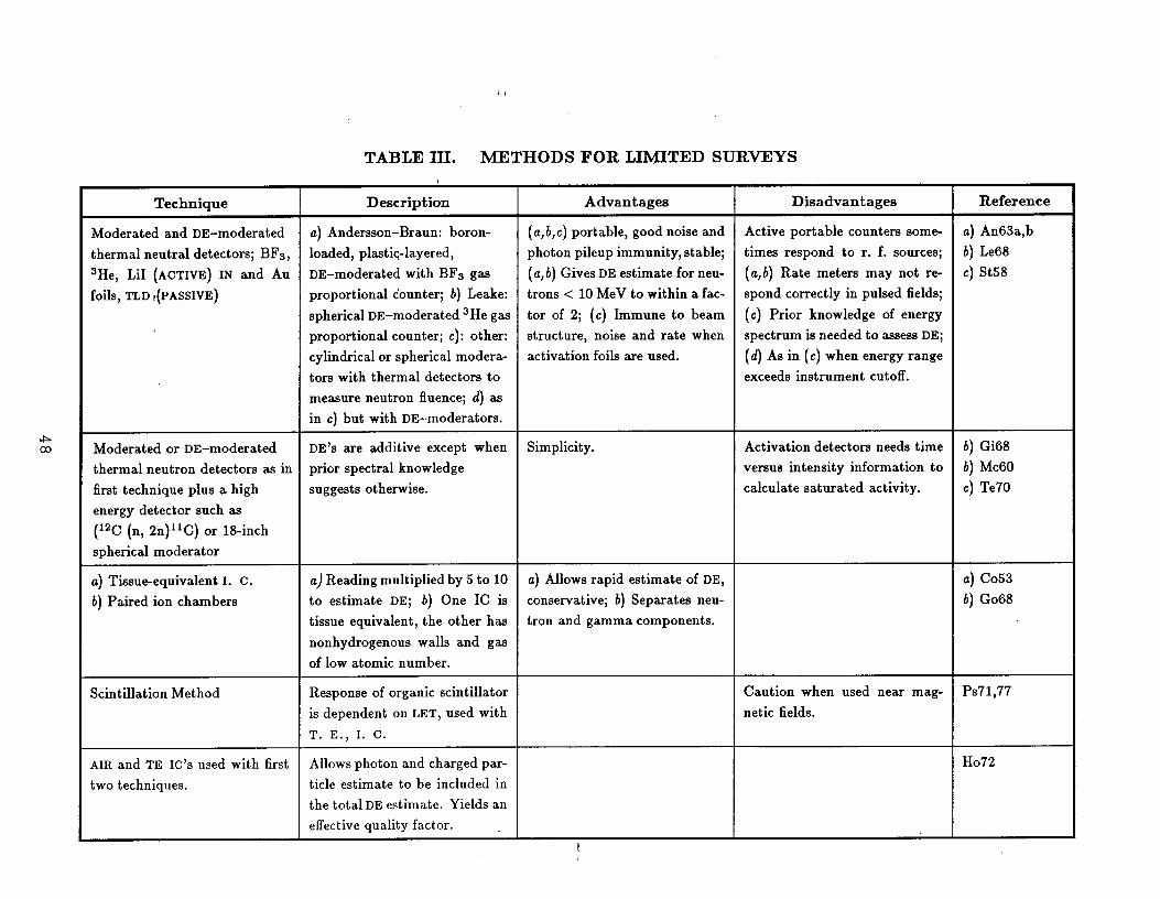
,1
TABLE III. METHODS FOR LIMITED SUR~YS
Technique Description Advantages Disadvantages Reference
Moderated and DE-moderated a) Andersson–Braun:boron- (a,~,c) portable, goodnoise and Active portable counters some a) An63a,b
thermalneutraldetectors; BF3, loaded, pl=ti~-layered, photon pileupimmunity,stable; times respond to r. f. sources; b) Le68
3He, LiI (ACTIVE) IN and Au DE–moderated with BF3 gas (a,b) Gives DE estimate for neu- (a,b) Rate meters may not r~ C) St58
foils, TLD ,(PASSIVE) proportional counter; b) Leake: trons < 10 MeV to within a fac- spond correctly in puked fields;
spherical DE–moderated 3He gas tor of 2; (c) Immune to beam (c) Prior knowledge of energy1
proportional counter; c): other: structure, noise and rate when spectrum is needed to wsess DE;
cylindrical or spherical modera- activation foik are used. (d) As in (c) when energy range
tors with thermal detectors to exceeds instrument cutoff.
measure neutron fluence; d) as
in c) but with DE-moderators.
Moderated or DE-moderated DE’S are additive except when Simplicity. Activation detectors needs time b) Gi68
thermal neutron detectors as in prior spectral knowledge versus intensity information to b) Mc60
first technique plus a high suggests otherwise. calculate saturated activity. c) Te70
energy detector such as
(12C (n, 2n)llC) or 18-inch
spherical moderator
a) Tissu*equivalent 1. C. a) Reading multiplied by 5 to 10 a) Allows rapid estimate of DE, a) C053
b) Paired ion chambers to estimate DE; b) one IC is conservative; b) Separates neu- b) G068
tissue equivalent, the other has tron and gamma components.
nonhydrogenous walls and gas
of low atomic number.
Scintillation Method Response of organic scintillator Caution when used near mag- PS71,77
is dependent on LET, used with netic fields.
T. E., I. C.
AIR and TE IC’S used with first Allows photon and charged par- H072
two techniques. title estimate to be included in
the total DEestimate. Yields an
effective quality factor. Ih
Extended survey efforts require the use of major techniques to ~sess the
major components of the radiation field. They may involve direct DE assessment
of accelerator-produced neutrons or some form of neutron spectroscopy, as well
as methods for ~sessing the other components, especially photons (Tables IV -
and V).
Monitoring environmental radiation at laboratory boundaries involves mea-
suring direct and air-scattered prompt neutrons when the accelerator is running,
and the natural radiation background when it is not. The neutron energy spec-
trum is usually assumed to be such that rem-moderated neutron detectors are
suitable.
The contribution of DE from accelerator laboratories to the general public is
often a small fraction of the natural background. This may make it difficult to
determine the accelerator’s contribution to the total DE. For new installations,
prestartup me=urements of the natural radiation background are recommended.
Once an accelerator is operating, one set of detectors at the site boundary may -
be gated on only when the accelerator is on; another set can monitor during
periods between accelerator beam pulses.
The primary photon contribution to the total DE diminishes more quickly
with distance from the accelerator than does the primary neutron component.
For accelerators whose energy exceeds about 10 GeV, muons may dominate at
small angles to the beam direction wherever the beam strikes. This is because the
muons are highly penetrating. Ionization chambers of suitable sensitivity can be
used as monitors, w can charged particle scintillation and solid state detectors.
Limited surveys to mewure accelerator radiation are appropriate if time and
effort must be conserved. If the purpose is, for example, to allow someone to
enter for quick repairs, the me~urements taken may be of little subsequent value.
However, it is good practice to record, in a log book, such details a the beam
species, energy, and intensity, target material and thickness,
thickness, detector-position, and measurement geometry.
49
shielding type and
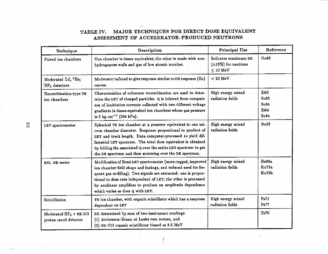
T~LE N. MAJOR TEiC~QUES FOR DIRECT DOSE EQ~ALENT
ASSESSMENT OF ACCELERATOR–PRODUCED NEUTRONS
Technique Description Principal Use Reference
Paired ion chambers One chamber is tissueequivalent;the other is made with non- Indicatesmaximum DE G068
hydrogenouswalk and gaaof low atomic number. (+15%) for neutrons~ 10 MeV
Moderated LiI, 3He; Moderatortailoredto giveresponsesimflarto DEresponse(En) <20 MeV
BF3 detectors curves.
Recombination-type TE Characteristicsof columnar recombination are used to deter- High energy mixed Zi62
ion chambers mine the LETof chargedparticles. Q is inferredfrom compari- radiation fields SU63
son of ionization currentscollected with two differentvoltage SU64
gradientsin tissu~equivalention chamberawhose gas pressure Zi64
is 3 kg cm-2 (294 kPa). SU84
LETspectrometer SphericalTE ion chamber at a pressureequivalentto one mi- High energy mixed R055
cron chamber diameter. Response proportional to product of radiation fieldsLET and track length. Data computer-processedto yield dif-
ferentialLETspectrum. The total dose equivalentis obtainedby folding the associatedQ over the entireLETspectrumto getthe DE spectrum and then summing over the DE spectrum.
BNL DE meter Modification of Rossi LET spectrometer (more rugged, improved High energy mixed Ba69a
ion chamber field shape and leakage, and reduced need for fr~ radiation fields Ku73a
quent gaa r-filling). Two signak are extracted: one is propor- Ku73b
tional to dose rate independent of LET; the other is processed
by nonbear amplifier to produce an amplitude dependence
which varies as does Q with LET.
Scintillation TE ion chamber, with organic scintillator which h= a response High energy mixed PS71
dependent on LET radiation fields PS77
Moderated BF3 + NE213 DE determined by sum of two instrument readings: Te70
proton recoil detector (1) Andersson-Braun or Leake rem meters, and
(2) NE-213 organic scintillator biased at 8.5 MeV
. .
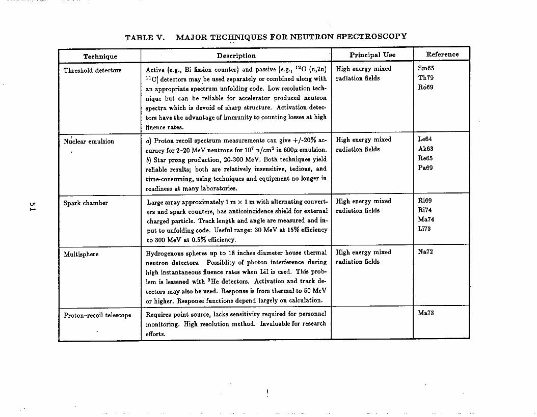
. . .
T~LE V. MAJOR TEC~Q~S FOR ~UTRON SPECTROSCOPYf{
Technique Description Principal Use Reference
Threshold detectors Active (e.g., Bi fissioncounter) and passive [e.g., 12C (n,2n) High energy rn~ed Sm65
llc] detectorsmay beusedseparately orcombined along with radiation fields Th79an appropriatespectrumunfolding code. Low resolutiontech- Ro69
nique but can be reliable for accelerator produced neutronspectra which is devoid of sharp structure. Activation detec-tors have the,advantageof immunityto countinglossesat highfluencerates.
N~clearemuhion a) Proton recoil spectrummeasurementscan give +/-20% ac- High energy mixed Le64
curacy for 2-20 MeV neutronsfor 10’ n/cm2 in 600p emubion.4 radiation fields Ak63
b) Star prong production, 2&300 MeV. Both techniques yield Re65
retiable results; both are relatively insensitive, tedious, and Pa69
timeconsuming, using techniques and equipment no longer in
readiness at many laboratories.
Spark chamber Large array approximately 1 m x 1 m with alternating convert- High energy mixed Ri69
ers and spark counters, has anticoincidence shield for external radiation fields Ri74
charged particle. Track length and angle are measured and in- Ma74
put to unfolding code. Useful range: 30 MeV at 15% efficiency Li73
to 300 MeV at 0.5% efficiency.
Multisphere Hydrogenous spheres up to 18 inches diameter house thermal High energy mixed Na72
neutron detectors. Possibtity of photon interference during radiation fields
high instantaneous fluence rates when LiI is used. This prob
Iem is lessened with ‘He detectors. Activation and track de-
tectors may abo be used. Response is from thermal to 50 MeV
or higher. Response functions depend largely on calculation.
Proton-recoil telescope Requires point source, lacks sensitivity required for personnel Ma73
monitoring. High resolution method. Invaluable for research
efforts.
I

For accident dosimetry, a simulated scenario, real or suspected, would be
appropriate. The scenario could involve in-beam or other high dose exposures
to personnel. Measurements are then made with appropriate dosimeters. These
measurements may help determine if a suspected exposure wm real, and to esti-
mate the magnitude of the DE.
Calibrating and interpreting dosimeters can involve appreciable effort. Simple
dosimeters such = those used in personal dosimetry, and simple survey instru-
ments, should be calibrated when possible in radiation fields that are similar to
those in which they will be used. Conversely, to interpret memurements made
with these instruments, one should know w much as possible about the radiation
field which W= me=ured.
Research efforts in health physics may involve me~urements of particle yield
and angular distribution M the beam hits the target (source term measurements),
absolute primary beam intensity or reaction cross sections. Shielding and particle
transport studies are also in this category.—.
For all determinations, choice of instrument and technique is often strongly
influenced by the characteristics of the radiation field. Types of fields encountered ~
include mixed radiation fields and pulsed fields. The energy distribution of the
field is also of interest for instrument selection.
At high energy particle accelerators it may be necessary to measure muons
at small angles to the beam direction. A simple measurement using an ionization
chamber with and without a suitable thickness of lead between the source and the
detector may suggest the presence of muons, and may provide a rough indication
of its magnitude. A more sophisticated method involves the use of a pair of
scintillator in coincidence in the form of a telescope such that the scintillator
size and distance between them defines the solid angle. Lead may be interposed as
a diagnostic tool to determine the presence of electron or hadrons. This method
h= the advantage of greater sensitivity because it detects discrete events with--
the reduced background afforded by its directional response. Its directionality
52
may also be of value in determining the source of the muons.
Detectors for Mixed Radiation Fields
The complexity of the radiation field, and therefore of radiation measure-
ments, increases with the energy of the accelerator. For electron accelerators
of energies below the threshold for neutron production, one is concerned only
with bremsstrahlung from beam-target interactions and x-rays from high voltage
generators and accelerator structures. To measure these, an ionization chamber
would be appropriate.
Neutrons are produced at electron accelerators when the electron energy ex-
ceeds the threshold for photoneutron production (1.7 MeV for Be, 2.2 MeV for
D, and G1O MeV for most other nuclei). At both proton and heavier ion accel-
erators, neutrons are produced when the energy of the beam particles exceeds
the coulomb barrier of the target nuclei. However, even at low energies, heavy
ions can produce copious neutrons through various exoergic reactions. As long
as the neutron energy does not exceed a few MeV, a moderator with a thermal
neutron detector will suffice for readings meant to guide worker protection. The
moderator should be one that responds proportionally to neutron DE. Examples
of such moderators are the Andersson-Braun (An63a, An63b) or Leake (Le68)
instruments.
Nonhydrogenous ionization chambers are useful to determine the contribution
of photons and charged particles to the total absorbed dose. When used with a
tissue equivalent ionization chamber, one can determine the absorbed dose due
to neutrons. A conservative value of quality factor (Q, usually 10)* can then be
used to estimate the total DE.
At some accelerators of intermediate energy, neutrons with energies in excess
of several MeV are produced, but the primary beam energy is less than that
* At the time of this witing, the NCRP has recommended that Q be increased by a factorof 2 so that a conservative value would be 20. Regulatory bodies have taken no action yet.
53
required to produce large numbers of pions (threshold of about 140 MeV). For
these machines, one must take into account the limited energy response of DE-
moderated neutron detectors. Significant numbers of neutrons may be produced
whose energies are too high to be detected adequately by moderated thermal
neutron detectors. This does not mean that DE-moderated or fluence-moderated
detectors (whose fluence response is approximately independent of energy within
its applicable range) would be useless. However, the degree of underresponse
must be previously established so that an appropriate correction can be applied.
The radiation field can be characterized beforehand through one of the more
extensive neutron spectroscopy techniques or by DE assessment. Examples of
neutron spectroscopy methods are given in Table V.
High energy accelerators produce abundant neutrons with
than 100 MeV (ICRU78), as well w muons from beam-target
energy greater
interactions at
forward angles. The high energy component of the neutron field becomes more
import ant when shielding is greater than about 2 meters of concrete, because of
the longer attenuation length of neutrons above 100 MeV. Photons and neutrons
are likely to be comparable contributors to the DE at electron accelerators, while
at proton and heavier ion accelerators, neutrons will dominate the field.
shielded areas, a significant fraction of the neutron DE is likely to be
by neutrons whose energy exceeds 20 MeV.
In thinly
delivered
Detectors breed on ionization recombination can exhibit a nearly ideal re-
sponse u a function of LET, and can therefore be very useful in determining DE
and Q (SU84). But, as discussed in SU84, these detectors have several disadvan-
tages. Only about 3% of the ion pairs recombine when the field is composed of
photons or other low LET radiations. Consequently, large chamber volumes are
needed to attain adequate sensitivity. Even then, it is difficult to me~ure DE
rates below 10 mrem/hr (28 nSv S–l).
Unfortunately, having large chamber volumes under high pressure introduces--
or enhances other problems, such as microphonics and noise. Also, the thick
54

metal containers needed to contain high pressures absorb the low energy part of
the spectrum. These detectors, because of their large size, tend to be impractical
for depth dose distribution studies. Similar problems exist for the sensitivity
of LET spectrometers, due to the saturation that can be encountered in pulsed
fields of high peak intensity. Consequently, few are used routinely at high energy
accelerator laboratories. In addition, an important theoretical concern currently
questions the issue of the Q/L relationship itself (De85, ICRU86).
Pulsed Radiation Fields
Me~urments of pulsed fields will be influenced by the field’s instantaneous
intensity, its duration and cycle time, and by the characteristics of the detector
and its circuitry. The amount by which the instantaneous or peak intensity of the
radiation field exceeds its average value depends on the accelerator’s repetition
rate or cycle time, and the length of time that the beam interacts with the target.
The peak or instantaneous radiation intensity, Ip, during the beam spill, is related – -
to the average value, I, by:
Ip = I/DF
where DF is the duty factor of the accelerator.
An instrument which accurately records the average dose rate of events spread
evenly in time might not be able to contend with high instantaneous dose rates
delivered in one or more short bursts. Yet a pulsed field which causes problems
with one detector may not with another.
The term “pulse” has two different meanings in the dosimetry of accelera-
tor radiation. The time that the accelerated beam interacts with the target is
variously called “spill,~ “burst,m or ‘pulse.m When instruments are used to de
tect discrete events and electronically process them, each event is also called a
“pulse.” To avoid confusion, the terms “beam pulse” and “detector pulse” will
be used. - -
55

hstruments which use count-rate meters are affected by the problem ass~
ciated with pulsed fields, that of beam targeting repetition rate. If the beam
continues to interact with the target for the few seconds necessary for a full re-
sponse by count-rate meters, there is no problem. But if the duration of the
beam spill is much shorter than the meter’s response time, and the time between
beam bursts is much longer, then the meter response is meaningless.
The following sections will discuss various types of detectors in terms of how
they are affected by pulsed radiation fields.
.
Ionization Chambers
Recombination is most pronounced in ionization chambers dominated by ionic
conduction. The air-filled ion chamber is an example. Most of the electrons
produced in the chamber attach themselves to the gas molecules within. As a
result, efficiency of charge collection at high dose rates is limited, az is collection -“
at large charge densities produced by intense beam pulses. The more quickly the
charges can be collected, the smaller will be the recombination.
Transit time in air-filled ionization chambers at normal temperature and
pressure will depend on ion mobility (about 1.3 cm/sec per V/cm for the slower
positive ion), chamber dimensions, the collection voltage gradient, and g= pres-
sure.
For chamber-filling gues which do not attach to free electrons to form neg-
at ive ions (argon, nitrogen, and others), the mechanism which limits collection
efficiency at high charge concentration is positive ion space charge, rather than
general recombination.
Within limits, steps can be taken to mitigate these ionization chamber prob-
lems. Keeping the volume constant, the charge separation potential can be in-
creased up to the point beyond which there is excessive leakage, breakdown,--
or ionization by collision of accelerated ions. Or the chamber volume may be
56

decreased, assuming that, in the process, acloser electrode spacing and there-
suiting increased voltage gradient is achieved. However, a smaller volume will
decre=e sensitivity.
As an example of a pulsed field situation, consider the case of an electron
linear mcelerator which delivers evenly spaced, on~microsecond beam pulses at
a repetition rate of 36o Hz. Assuming that the dose associated with each beam
pulse is one nanorad (10 pGy), the dose per hour would be 1.3 mrad (13 ~Gy).
These are both relatively low values. The instantaneous dose rate, however, is
3.6 rads/hour (10 pGy/s). Many instruments can handle such dose rates; others
cannot. An instrument which can handle large dose rates for an extended period
of time will certainly perform well for shorter time periods.
If recombination is suspected, it may be possible to ~sess and compensate
for decre~ed collection efficiency. Two sets of me~urements can be made in the
same field at different collection voltages. This tw~point technique for ~sessing
collection efficiency is described in ICRU-82.—-
Another appromh is to compare the ion chamber’s integrated dose values
with that of LiF TLDs which do not show limiting effects at high dose rates.
When the charge is deposited in a time that is shorter than the charge col-
lection time, the important factor is the total charge density that is deposited,
rather than the deposition rate. The problem of recombination at high charge
concentrations is compounded when the beam cycle time is less than the charge
collection time for the ionization chamber. Each beam pulse’s contribution to
charges in the chamber will then overlap. The result will be a larger recombi-
nation than would be the c=e for a single isolated beam pulse. In our example
above, however, the interval between beam pulses is 2.8 ms, which is long com-
pared to the time necessary to clear most ionization chambers of charges from
the previous pulse.
Appendix C gives a case in which successive beam pulses arrive at the ion--
chamber in a time which is short compared to the time necessary to sweep charges
57
out of the ion chamber (B066, ICRU82).
Proportional Counters
Pulse pair resolution time is a measure of the ability of electronic circuitry
to resolve closely sp~ed events. The circuitry’s performance sets a limit on
the ability of gas proportional counters to count each event when dose or event
rates are high. The pulse durations can be electronically reduced. However, the
mechanism that determines the rise time of the event (ion multiplication and
collection) limits how short the pulse can be. Further differentiation of the pulse
will result in a decre=ed pulse height which lowers the signal-t-noise ratio and
makes the detector system more susceptible to interference from photon pileup.
Proportional counters do not exhibit dead time * do Geiger-Muller counters.
Instead, the collection voltage typically drops less than one volt during multi-
plication and charge collection, which does not appreciably lower the electronic
gain of the detector. Also, the region of the anode over which the multiplication --
takes place is very small, leaving the rest of the anode wire undisturbed.
Gas proportional counters with reduced volume may be used to lessen count-
ing losses, provided one can accept a corresponding loss in sensitivity. Also,
substitution of less sensitive counters of the same volume may be possible, such
as BF3 tubes depleted in l“B.
Geiger-Muller Counters
Geiger-Muller (G-M) pulse counters exhibit long dead time, on the order of 1
microminute, and can become temporarily incapacitated by a rapid rate of events
(NCRP85a). However, some G-M counters are designed to switch from pulse to
current mode when event rates become excessively high.
Obviously, for accelerators with beam pulses of a few microseconds or less,
one can never detect more than 1 G-M detector pulse per beam pulse.
58

Scintillator/PhotomultiDlier Detectors
The count rate capability of scintillator/photomultiplier detectors depends
critically on whether the photomultipliers high voltage supply can stay regulated .
during the high current drain ~sociated with high count rates. Given sufficiently
high count rate, temporary failure of linearity is ~sured.
The size of the detector in scintillator/photomultiplier systems can be de-
creased to reduce the current drain of the photomultipliers. However, this may
not be practical in situations where the scintillator must be large to contain the
energy of the photon in the photopeak. Some improvement can be made by
incre=ing the power available to the l=t dynodes of the photomultipliers.
Photomultipliers are very sensitive to magnetic fields (even to that of the
earth), and they should be used with caution near the stray fields of particle
accelerators and their ~sociated magnets. The effects of magnetic fields depend
on the field strength and the orientation of the photomultipliers tube in the field,—.
and can range from slight to complete loss of signal, or a change in position of the
photopeak in a multi-channel analyzer. An indication that poor response maybe
due to a magnetic field is to rotate the detector about the point of measurement .
and see if there is an unwarranted change in response.
- Some commercial suppliers of detectors either neglect to enclose them in mag-
netic shields or do not extend the shield beyond the face of the photomultipliers.
A rule of thumb is that the magnetic shield should extend beyond the photomul-
tipliers face by a distance equal to the photomultipliers diameter. In addition,
all magnetic shields are only partially effective. It is quite difficult to shield a
photomultipliers tube well enough to operate in a 100 gauss (0.01 T) field.
The amplitude of signals from scintillator/photomultiplier combinations will
vary with temperature. Both scintillator and photomultipliers exhibit temperature-
related gain variations. Field instruments, because of the uncontrolled tempera-
tures where they are generally used, may be particularly prone to such problems--
when used with narrow-window, single-channel analyzers. Instruments of the
59

same type must be individually checked prior to their first use, because differ-
ences may exist. Although these temperature effects are not large, they should be
evaluated, w should temperature effects on the auxiliary electronics (HV supply,
amplifier, discriminator, and so forth).
Fine Structure on the Beam Pulse
A simplifying assumption made thus far is that the intensity of events during
beam spill is uniform. This is not always the c=e. Fine structure on the beam
spill can be found by observing detector events on an oscilloscope. If the oscil-
loscope’s horizontal time sweep is triggered by a timing marker coincident with
the start of beam targeting, and beam spill duration is presented on the x-axis,
fine structure will be seen as one or more spikes or peaks on the y-axis.
If the observation is made with a scintillator/photomultiplier system, high
intensity fine structure may exceed the capability of the photomultipliers high -.
voltage power supply. If so, the oscilloscope display will indicate few or no events
during the period of highest beam loss—a dropout will result rather than a spike.
Usually, radiation mewurements taken at some distance from the target and
outside of thick shielding will not be adversely affected. The potential remains,
however, and should be considered.
Often, research groups will have detectors in the beam which can indicate the
amount of fine structure on the beam spill, which can help the health physicist
tell if a potential for counting loss exists. Scattering and degradation of neutron
energy in both nearby shielding and moderators of neutron detectors will spread
the arrival time of the events. For BF3 moderators that are 6 cm thick, half
of the events from an instantaneous burst will not be captured until about 100
microseconds or more have elapsed. See Fig. 1 (Je64).
-.
60

\
Typical 20-~segate width
o
0 I I I 1 I I
500 400 300 200 100 0
Time (psec)
Fig. 1
3.5 PERSONNEL DOSIMETRY
Beta-gamma Dosimetry: The problems involved with beta-gamma dosimetry
at an accelerator are by no means unique. The radioisotopes 64Cu, 56C0, 5’C0,
58C0, 6oCo, 5gFe, 54Mn, 56Mn, 22Na, and 24Na are those that produce most of
the dose to personnel, regardless of whether the source is a proton or electron
accelerator. And these isotopes, wide from being primarily neutron-deficient
ones, might be encountered in any other radiation environment. Finally, at an--
accelerator facility, almost all of the radiation dose to personnel comes from ra-
61

dioactivity induced in the accelerator’s components rather than prompt radiation
during accelerator operation. Personnel dosimeters therefore can be those ac-
ceptable elsewhere, such w film badge or TLDs. DOE requires that beta-gamma
dosimeters are accepted under the DOELAP program (DOE86).
Since the activation at an accelerator is more of a volume process than a
surface one, it is rare for the beta dose to be important. However, the prudent
Radiation Safety Officer should keep the possibility of beta exposures in mind.
In the rare case where prompt ionizing radiation is important, it would always
be either photons (bremsstrahlung) from an electron accelerator or muons from
either a proton or an electron accelerator (Ne76). For these also, a film badge or
TLD would be adequate.
o
Neutron Dosimetry: The situation for neutron fields is much more compli-
cated at accelerators than other facilities. The reason is that the range of neutrons
energies is greater—from thermal to several GeV. The fraction of the DE due to —=
the different neutron contributors can vary markedly from one spot to another
at the same accelerator. An example is measurements on the CERN Proton
Synchrotron shown in Table VI (reproduced from Ri73). Both points would be
considered to be behind thick shields. In such a situation, it is clearly necessary
to measure all of the components.
Measurements such w those in Table VI are difficult to do, even with large
equipment that is only semi-portable. As another example, in H084, three differ-
ent me=urement systems were compared at seven locations around CERN. The
ratio of the highest response to the lowest response was M high as 1.8. Mea-
surements at the Serpukhov proton synchrotron comparing six different systems
are also reported in H084. Here the ratio of the highest response to the low-
est response was w high as 3.6. Memurement systems used included multiple
ionization chambers, remmeters, moderated detectors, recombinant ion ionization
chambers, and LET spectrometers. While the above measurements were all on--
proton accelerators behind thick shields, the results are probably also valid for
62

TABLE VI.
COMPOSITION OF RADIATION FIELDS
ABOVE THICK SHIELDS AT THE CPS
Radiation
Thermal neutrons
F=t neutrons
(0.1 MeV < E <20 MeV)
High energy particles
(E >20 MeV)
q-rays and ionization
from charged particles
Percentage of Dose Equivalent
Above concrete Above target throughshield bridge earth shield
11–12 I < 1–3
5&70 I 10-37
2-25 I 52–89
2–19 I 1–13
thick shields and electron accelerators. Obviously, if agreement between complex
mewurement systems is so poor, it will be worse for personal dosimeters.
A quick survey of some DOE accelerator laboratories showed three labora-
tories using NTA film and two using quasi-albedo dosimeters with TLDs. One
facility found that the ratio of thermal neutron fluence to total neutron DE var-
ied only about an order of magnitude, so this lab me~ures thermal neutron
fluence with TLDs. The neutron DE is then calculated using a ratio that may--
--
63
overestimate the true DE by a f~tor of 6 or underestimate it by a factor of 2.
One facility intends to switch to CR-39 track-etch detectors, one is considering
it, and one has tried CR-39 and is abandoning it. At this time it is not possi-
ble ‘to recommend any personnel neutron dosimeter u being very satisfactory. -
Fortunately, neutrons probably contribute less than 10% of the total person-rem
at any high energy accelerator. Neutrons may be significant at the entrances to
lower energy accelerators, however (NCRP84).
Consideration should be given to accident dosimetry. In an accelerator en-
vironment, the only accident that involves special dosimetry problem is when
a person is exposed near a point of high beam loss without the interposition
of customary shielding. This might occur when someone is inside the accelera-
tor housing with the beam on or when a primary beam escapes to an occupied
area. In such cases, the nature of the radiation field may be quite different than
that normally encountered and interpretation of personnel dosimeter data corre-
spondingly difficult. In a few cases, health physicists have evaluated the induced -.
radioactivity of the body u a method of estimating the accident dose (Ba66,
Di73, Je68, K065, Le65, Mi72).
3.6 EXPERWENTER ACCESS TO BEAMS
-Experimenters often must have access to beam are= when the particle beams
are on, to make adjustments or to investigate equipment problems. Such work
can be carried out without radiation danger if beams are well-defined and the
operator does not have to place his or her body into the beam. On the other
hand, it is e~y to conceive of situations wherethe experimenter inadvertently
places part of his or her body in the beam; the experimenter thinks the beam
is off when in fact the beam is on; or, the experimenter intentionally works in
the beam, failing to appreciate the radiation doses that can result. Any program
which permits experimenter access should address the following criteria.
● Training. Any individual with access to secondary beams should be specif---
ically instructed on what activities are acceptable around the beam. This
64

●
●
information should also include biological effects of radiation and dose rate
information. Only individuals who have had these instructions should be
authorized to work under beam-on conditions.
Limits According to Beam Intensity. Access to beams should be decided
b=ed upon the beams’ dose rates. Some beam intensities will be so low
that no controls are needed. Conversely, some intensities are so high that
no access should be permitted. An example of such a system used at
Brookhaven National Laboratory is shown in Table VII.
Beam Barriers. Barriers around the beam serve = important safeguards
against accidental exposures. These barriers should be substantial enough
to prevent e=y removal (a beam pipe rather than simply marking the path
with tape) and should enclose the beam specifically, not identify a beam
area.
Beam-On Indicators. Visual and audible indicators which are activated by
the beam serve as important reminders to people working in the area that-“
the beam is on.
4. ADMINISTRATION OF A HEALTH PHYSICS PROGRAM
4.1 RECORDS
Recordkeeping is a necessary part of all health physics operations, including
those at accelerators. Records will help to show that the health physics program
is adequate, and can help analyze and solve future safety problems. Records are
needed for legal purposes, to protect the facility in case of a lawsuit, or to ~sist
in investigating contested, unusual, or accidental personnel exposures. Keeping
records, moreover, is mandated by DOE, and the data so produced will provide,
for audits, a trail of compliance with DOE requirements.
--
65

,4
TABLE VII. GENERAL GUIDELINES FOR AGS RADIATION SECURITY
SYSTEM CLASSIFICATION AND APPLICATION
Potential RadiationAllowable Radiation Enclos lre under Abnormal Conditions
Area Beam Small Source Area Beam Minimum Security Purpose of
R/hr p/sec/cm2 Residual Q 3“ R/hr Access Barrier Gate R/hr p/sec/cm2 System Security System
Absolute Hardwire, Failsafe Preventing
> 300 > 3 X, lo’ >3000 Prohibitioti Impregnable Primary Dual Access or Beam
Special Fuuy a) Hardwire, Fahafe, a) Controlling
:300 <3 x’ 107 <3000 Procedure Enclosed Primary Dual Access or Beam
>300 >3X1O’ 6) Not Specified
<30 <3X10⁶ <300 HP Wab/ a) Hardwire, Faibafe a) Controlling
Supervision Fixed Fences Secondary Access or Beam
<300 >3 X10⁷ b) Active, Faibafe b,c) Preventing rise
>300 >3 X10⁷ c) Hardwire, Faikafe to these levelsDual
<3 < 105 <30 Authorized Fences/ Locks a) Active, Failsafe a) Controlling Access
Individuals Barriers and/or Beam, Warning
<30 <30 x 106 b) Active, Failsafe, b) Preventing rise
<300 <3X10⁷ Hardwire, Failsafe, to these leveb
>300 >3 X10⁷ Dual
>.1 <3000 <.3 Radiation Noticeable None a) Active a) Alarm on Excessive
Warning Signs Radiation
<3 < 105 b) Dual, Active b,c,~ Preventing rise
<30 <3X10⁶ c) Active, Faibafe, to these levek
>30 Dual>3 X10⁶ d) Hardwire, Faibafe
:.005 <50 <.005 No Control None None a) None
<.1 <3000 b) Active b,c,d) Preventing rise
<3 < 105 c) Active, Failsafe, to these levelsDual
>3 > 105 d) Hardwire, Failsafe,Dual

The principal guide for retention periods is DOE Order 1324.2—Records Dis-
position, Chapter V—Retention of Contractor Records, dated 5/28/80. Other
recordkeeping requirements are scattered throughout the DOE Orders. Table
VIII is a compilation of records that are needed and the required retention pe- “
riods. The health physicist will probably find that other records are necessary
for his own purposes. At this time, DOE Order 1324.7 has placed a temporary
freeze on destroying any records related to health and safety.
Log books may be used to record information which must be available to
rotating shifts of the accelerator’s operators. Logged information which needs
to be =sociated with a particular activity or facility location can be kept in
separate files. At a large facility, it is often e=ier to retrieve information if it is
filed in the log book by subject, instead of in chronological order. The ability to
retrieve historical data about radiation patterns, shielding, and so forth is useful
when a new operating condition arises. While this is true for either large or small
facilities, retrieval is usually easier at smaller sites because of the more limited -.
possibilities and closer proximity of the physical are~.
Control of access to the records should be consistent with requirements of
the Privacy Act.
Systems for recording radiation exposure are covered in ANS166.
Storage of records for the required retention periods is difficult. Government
repositories require very specific instruction to retain stored records for more
than five years. Storage of records in computer format is a compact way of doing
it but it is necessary to review the system whenever there is a change in computer
equipment. For example, one laboratory had been using magnetic tape storage.
They found there had been a change from 7-track to 9-track tape and they were
no longer able to read their tape archives. Future changes in computers over a
-.
67

TABLE VIII. RECORD RETENTION
Item Filing Unit Title and Description Retention Period
1 Individual Radiation Dose Records 75 years
2 Radioactive Waste Disposal Records Permanent
3 Radiation Detection Instrument Calibration Records 75 years
4 Inspection Surveys Permanent
5 Nuclear Counting Lab Analysis Reports
and Quality Assurance Records Permanent
6 Interlock Review and Test Notification Records Permanent
7 Radioactive Sources Inventory and Records Permanent
8 ALARA Committee Minutes Permanent
9 On–Site Radiation Monitoring Records Permanent
10 Radiological Facilities Records Permanent
11 General Correspondence Files Permanent
12 Site Environmental Reports Permanent
13 Environmental Contamination Records Permanent
14 Environmental Protection Program Procedures Permanent
(includes Environmental Evaluations,
Nonradioactive and Radioactive
Pollution, Decommissioning and
Environmental Reviews
15 Radiation and Contamination Surveys, 75 years
Air Sampling Logs
16 DOE Reports — Annual, Semi–annual, Permanent
- Qu-arterly, Monthly
17 Significant Occurrence Reports Permanent
18 Appraisals, Audits, Inspections 10 years
(includes those conducted by DOE and internal)
19 Procedural Manuals/Handbooks, e.g., Permanent
Radiation Guide or Safety Manual
20 Laboratory Safety Committee/ PermanentSubcommittee Files
21 Budget and Cost Files 2 years
22 Experiment Review Files Permanent
period m long w 75 years could make all present memory methods unreadable.
In addition, magnetic recording media of today are sufficiently stable that storage
of only l&20 years is practical (NRC86). This same reference contains valuable
information concerning record storage in many other formats including paper.
4.2 AUDITS
Internal audits of a radiation safety program are required by DOE Order
5480.lA. If properly implemented, internal audits will usure the top levels of
management that radiation safety is kept consistent with DOE orders and labo-
ratory policy.
Recommendations for Audits
The audit program should fit the size and nature of the facility. It is intended
as an addition to, not a replacement of, an inspection program. An inspection is—=
usually a rather informal ‘walk through~ by a safety person, to list discrepancies
and check if there has been follow-up on action items. However, an audit should
be more thorough, better documented and involve management.
Following are suggested audit procedures.
-o
●
●
●
Determine the elements of the program to be audited.
Determ-ine how often each element should be audited.
Develop and announce the schedule each year.
Leave the schedule flexible so that unscheduled but timely subjects can be
substituted.
The audit format should be u follows:
Select the time to minimize impact on laboratory operation.
Select the appropriate audit team.--
Develop the detailed subjects to be addressed.
69

●
●
●
●
●
●
Formally announce the details—time, subjects, and audit team—to both
line and top management. The announcement should strongly encourage
participation by the
Conduct the audit.
Draft a report.
Obtain concurrence
line organization.
from top management and the line organizations on
action items and dates of completion.
Issue the final report. The report should be signed by top management,
line management, and the Radiation Safety Officer.
Follow-up should document completion of action items.
The audit team should use the following approach:
●
●
●
●
Review relevant external standards, such as DOE orders.
Compare the Laboratory Policy and Program to the external requirements. –.
Review the line organization files which document compliance and impl~
mentation of their program.
Conduct spot inspections to compare actual practice with records.
. Frequency of internal audits should be based on changes in the program or
facilities. Major program elements should be reviewed every three to five years,
or if a significant change occurs. Other elements may need review only when
significant changes occur.
The members of the audit team should be selected for their expertise in the
subject being audited, yet should have no conflict of interest. The charge to the
audit team should be well thought out and specific. Adequate time should be
given for the team to fulfill their charge.
Experts from outside the facility can be a useful way to either supplement
expert ise or obtain a more independent review. Smaller facilities may have to--
rely more heavily on outside experts.
70

4.3 WRITTEN PROCEDURES AND ADMINISTRATIVE CON-
TROLS
For clarity, written procedures and administrative controls are treated sepa- -
rately within this section. Written procedures are addressed first and in detail,
since administrative controls frequently refer back to written procedures that
need to be modified.
Definition of Written Procedure
A written procedure is a document that details or describes an operation by
breaking it down into specific steps. Generically known w Written Procedures,
the document may be also be called Standard Operating Procedure, Program
Statement, Radiation Rules, Radiation Safety Notes, or Operating Instructions.
Regardless of title, a written procedure is a document that addresses a single
issue or a spectrum of health physics issues dealing with accelerator operation or —.radiation safety.
Written procedures serve a number of important functions, three of which are
especially significant. First, they provide personnel in management, operations,
and safety with spelled-out statements of understanding about important ~pects
of a facility or operation. Second, the document that is properly drafted and
followed can significantly mitigate potential for serious incidents. And third, a
written procedure serves as a valuable training aid for the health physics staff,
personnel in facility operations, and experimenters.
Situations that Call for Written Procedures
Any high risk operation, routine or not, repetitive or occuring only once,
should be considered to see if a written procedure would be appropriate. As a
minimum, written procedures are needed for operations that are not obvious to
trained personnel, that involve unique equipment, could adversely affect people--
or the environment, or which require a sequence of steps.
71

Specific instances where written procedures are appropriate and recommended
include:
●
●
●
●
●
●
●
●
●
searches of secured high radiation areas
bringing new beam lines or experimental caves into operation
interlock checks
calibration of area radiation monitors
monitoring equipment or materials for rele=e to public domain
intra-site transfer of radioactive or contaminated materials
off-site shipment of radioactive or other hazardous materials
handling and disposal of radioactive wastes, liquid or solid
decontamination of facilities or equipment.
Besides a written procedure, a risk ~sessment or safety analysis may be ap- _.
propriate for those operations which could endanger personnel, the environment
or the public in an accident or could significantly disrupt facility operations.
Specific operations which fall into this category may include:
●
●
●
unusually hazardous in-beam targets, such u kilocurie tritium targets or
uranic and transuranic targets
high pressure g= targets where cat~trophic rupture could disperse radioac-
tive material
any operation or experiment that poses special concerns of either fire or
explosion in are= of radioactive cent aminat ion or high radiation.
Elements of a Written Procedure
A written procedure is usually a formalized document that addresses crit-
ical issues and is made readily available or posted at locations appropriate to--
the operation, such as the work area, control room, health physics office, beam
72

channel or shielded enclosure entrance, or experimental cave entrance. A written
procedure may include the following suggested elements:
●
●
●
●
●
●
●
an appropriate title with current date and expiration date
an introduction that states the objective(s) of the document
clearly defined statements of the steps necessary to achieve the objective(s)
a statement identifying responsibility and qualified operators or individuals
a safety msessment or accident analysis if applicable
samples of forms, checklists, tags, or other auditable documentation that
are appropriate to or referenced in the written procedure
an approval sheet for reviewer(s).
An exception to the above format for written procedures is what is sometimes
called a “temporary procedures book.” This book is a method of establishing
short-term or temporary procedures for radiation safety where a need arises out —.
of unanticipated, limited, or emergency operations. Rules or procedures entered
in the book are readily revised or cancelled depending upon the circumstances
that dictated their need. Alternatively, these procedures may be developed into ~
formalized written procedures w operating experience is gained and variable
operating parameters stabilize.
The nature of an operation or issue influences the comprehensiveness of a
written procedure. High risk operations, for example, should be evaluated from
standpoints of accident and risk probability. b an accident or failure scenario, the
procedures should evaluate the potential for radiation exposure of the facility’s
personnel and the general public. Procedures written for low risk and minimum
impact operations need only address operation b=ics and be brief.
Review and Approval of Written Procedures
A written procedure should have provision for review, approval, and, if ap---
propriate, periodic recertification.
73
Review and Approval: The issues or operations addressed in a written pro-
cedure will largely dictate which scientific disciplines and management levels,
besides health physics and safety, need to be involved in the review and approval
process. High risk operations such = high pressure tritium gm targets should be
reviewed and approved by experts in the fields of metallurgy and high pressure
physics, along with upper level management of the facility and health physics.
Conversely, the review and approval process for personnel searches, for exam-
ple, may only need approval from local operations, safety, and health physics
management. Regardless of reviewer or management level, a signed approval
shows that the reviewer is satisfied with the procedure, and accepts a share of
the responsibility.
Recertification Review and Approval: Periodic recertification reviews of writ-
ten procedures are recommended. A on-year time frame is re~onable, but de-
pends on the particular procedure or operation. A recertification review is always
required, regardless of time since the l~t review, if the scope or nature of an op- —.
eration significantly changes. The more hazardous the operation covered by the
procedure, the smaller the operational change required to prompt a recertification
review. The approval chain for review should track changes in the procedure. If “
an operation has become more hazardous, the rewritten procedure should reflect
this, and the corresponding approval levels reviewed and adjusted. Conversely,
if an operation has become less significant, the approval levels can be relaxed.
Administrative Controls
Written procedures that address issues of accelerator health physics may also
specify some level of control to wsure safety of the facility and its personnel. The
controls may be physical barriers such m a locked door, or they can be adminis-
trative, or a combination of both. Administrative controls may be permanent or
temporary. However, in operations where an accident could have major impact
on personnel, the facility, or the environment, administrate ive controls are not--
recommended for long-term use, because human error can occur.
74
Administrative controls are generally a flexible form of safety assurance.
Many times they are implemented where physical barriers do not exist, are inap-
propriate, or are temporarily deactivated. Administrative controls usually involve
a situation where a responsible operator, experimenter, or safety official controls
access to or surveillance of an operation that is potentially hazardous. Again,
the danger is that administrative controls leave more room for human error.
Operations that Reauire Administrative Controls
Administrative controls are likely to be most effective at accelerator facilities
where operation areas are small enough to see or hear anyone in them, and where
elaborate electrical, mechanical or electromechanical controls are not found or
necessary. Working from specific written procedures and simple physical control
mechanisms, the operator (and/or safety person) controls access to and provides
surveillance over the hazard area.—.
At large, complex facilities, administrative controls are more likely to be im-
plemented for only brief periods. Such controls are, for example, put in place
during times of simultaneous facility construction and operation, while the fa- .
cility is being operated with safety or interlock systems under repair, or when
experimental demands require short-term occupancy of an area normally con-
trolled by barriers. Operator, safety, or other authorized personnel will then
provide the control, operating from specific written procedures which either have
been formalized or are in ‘Radiation Rule Bookn form.
Elements of Administrative Control
Implementing administrative control requires a standardized record system
and a clearly delineated chain of command. Controls such m temporary phys-
ical barriers, controlled key issues for controlled locks, and/or guard or watch
personnel are also effective in leaving u little room for human error m possible.--
Administrative controls should be reviewed frequently to ~sess their adequacy
75
and continuing need. Frequency of review depends on the degree of hazard. Fi-
nally, a condition that continually requires administrative control suggests that
a physical control system should be put in place. Administrative control should
not be continued for the sake of convenience or easy access.
4.4 RADIATION SAFETY STAFF
An accelerator health physicist should be involved M soon u design of an ac-
celerator begins. The health physicist should give guidance to ensure the facility
will meet applicable federal, state, and local requirements for radiation protec-
tion. Prior to the start of operations, the facility management should appoint
a Radiation Safety Officer
and insure that sufficient
provide an effective safety
(sometimes referred to as Principal Health Physicist)
radiation safety personnel are hired and trained to
program.
The Radiation Safety Officer should:-.
●
●
●
●
Report to the top level of management. Advise top management on all
matters concerning radiation.
Define, with the concurrence of top management, the radiation safety re- ~
quirements and assure compliance with DOE Orders.
Monitor, and report to top management, the effectiveness of the radiation
safety p~ogram.
Have authority to stop activities which appear to present imminent hazard
or which violate the facility’s safety policy.
The radiation safety staff should have a broad range of expertise. If it is
necessary to hire staff without the required expertise, training should be provided,
or the needed expertise should be made available either by a radiation safety
committee or outside consultants. Required
● Physics. Knowledge of the physics of--
particle types and energy is essential.
76
arew of expertise are = follows:
the interactions for the appropriate
●
●
●
Radiation Physics. Calculations of shielding and activation are needed in
order to predict both prompt and residual radiation levels.
Operational Health Physics. There should be a good understanding of .
radiation and protection methods, dosimetry, and regulatory requirements.
Familiarity is also needed with electronics, accelerator design and operation,
beam transport, and experimental techniques.
Often it is difficult to hire professionals trained in all the above are=. It is
recommended that all radiation safety staff go through training to orient them to
the particular accelerator facility. The following elements, u appropriate, should
be included in the training:
●
●
●
●
●
●
✎✘
●
●
●
●
●
●
c
●
Fundamentals of Radiation Protection
Instrumentation
Residual Radioactivity /Contamination
Radiation Emergencies
Transport of Radioactive Material
Storage of Radioactive Material
Radioactive Wrote
Radioactive Sources
Personnel Dosimetry
Accelerator Operation
Beam Transport
kterlock Systems
Shielding Calculations
Review of Operations/Experiments for Radiation Safety--
Regulatory Requirements—DOE, DOT, EPA, etc.
77

● Environmental Protection.
Elements of the above outline should also be included, in as much detail ~
the particular facility requires, w part of a technician training program.
Both staff and technical personnel should be encouraged to keep current by
reading the literature and attending professional conferences. Seminars and short
courses can be invaluable for staying up-t~date with regulatory changes. Out-
side courses are available, especially at the technical level, which can aid training
in fundamentals. Finally, laboratory policy should encourage and support cer-
tification by professional societies such as the National Registry of Radiation
Protection Technologists (NRRPT) for technicians and the American Board of
Health Physicists (ABHP) for staff.
h addition to the full-time health physics staff, it may help to have other
persons review new and ongoing health physics problems. These persons can be
either reviewers or part of a Radiation Safety Committee. -“
Reviewers can provide an outside perspective on programs. They may be
used as a part of the audit program (see Section 4.2) or x a more informal
reviewer. Such reviewers may be recruited from other personnel with an interest
in radiation safety; they may also be health physicists from other facilities.
“The Radiation Safety Committee should be formed of representatives from
such groups u health physics, radiation groups, accelerator physics, operations,
and interlock design and maintenance groups. It should meet, u necessary,
to review new accelerator or experimental configurations, changes in interlock
philosophy, significant staffing changes that affect radiation safety, and so forth.
They should report to top management. The committee should also be available
to review problems brought to their attention by concerned staff members or
visit ing experimenters.
-.
78

5. DISMANTLING, DECONTAMINATION,
AND DECOMMISSIONING
‘The health physics involved in dismantling and decommissioning accelera- -
tors should be considered during the facility’s design, operation, and expansion
or modification. Original plans for decommissioning should be updated to ac-
commodate any modifications to the facilities, or any changes in disposal options.
Plans to decommission should also respond to changes in radioactive waste reg-
ulations and prevailing attitudes on releme or reuse.
5.1 FACILITY DESIGN
The eventual decommissioning of an accelerator should be planned for even
= the facility is being designed and built. The goal should be to keep radiation
exposure during dismantling at ‘ALARA~ levels—~ low M re~onably achiev-
able. —.
During construction, materials should be chosen that will not be significantly
act ivated by the accelerator, to minimize radiation exposure at decommissioning.
Prudent initial design could mean the difference, at decommissioning, between
having to discard material or incur additional costs, and being able to recover
valuable resources without undue exposure of personnel (ANS178, G076, IAEA79,
Pa73).
Certain design measures to keep exposure low at decommissioning would
clearly add significant cost to initial construction. A cost analysis should be made,
comparing the costs added at the time of construction to those of measures which
would otherwise be needed at dismantling time. Potential decontamination costs
should be added to the cost analysis. Decontamination can add significantly to
the cost of some decommissioning projects, whereas taking action during design
may be quite cost-effective.
79

5.2 FACILITY OPERATIONS
Personnel who will be operating an accelerator facility should insist on ad-
equate ‘m-builtn drawings from the construction contractor. During operation
of a typical facility, modifications will undoubtedly be made to the accelerator,
the experimental are=, and the support facilities. Whenever possible, the same
meuures for keeping radiation exposure ALARA during decommissioning should
be included in the design of any expansions or modifications. Changes should be
added to the “as-builtn drawings to keep them up-t~date.
The documentation of how systems and structures went together (both orig-
inal construction and subsequent modifications) should show names of responsi-
ble people who understood the construction details. When feasible, these people
should be included in the planning for dismantling and decommissioning.
Most large accelerator facilities provide storage space for excess materials.
These area, sometimes referred to m ‘bone yards,n are often outdoors and tend – -
to include both activated (“hot”) and nonradioactive ( ‘cleann ) materials and
equipment. Experience h= shown these storage yards to be a tremendous detri-
ment to efficient decommissioning if they have not been carefully controlled and ~
the stored materials rigorously segregated according to radioactive content. Ad-
verse effects from sloppy storage can include unnecessary exposure of personnel
during cleanup operations, inadvertent rele=e of radioactive material to commer-
cial scrap dealers or public w~te sites, or inappropriate routing of clean as well
as radioactive material to radioactive burial sites. Strict control of storage is thus
recommended and the facility’s health physics organization may be the logical
choice for maintaining such control. Regardless of who is responsible, adequate
control of the storage area requires support from operations management during
those times when keeping materials segregated may not seem ‘convenient.”
-.
80
5.3 PLANNING DISMANTLING AND DECOMMISSIONING
Health physics considerations for decommissioning particle accelerators cen-
ter around two primary =pects. One is the dose of radiation that decommission- -
ing personnel may receive while dismantling, decontaminating, and preparing
radioactive components of the accelerator for shipment. The second aspect is
potential radiation hazard to the general population. Public exposure can oc-
cur from interim, on-site storage of radioactive components or from transport to
other sites, or to retrievable storage or wrote disposal. The public may be ex-
posed to radiation when accelerator components or structures containing induced
radioactivity are reused (Op79).
B-cd on these considerations, all radiation exposures should be planned so
as to keep radiation exposure ALARA. The collective dose should be minimized
for both the decommissioning personnel and the affected general population. Ra-
diation Work Permits would be appropriate for many tasks during the course of _ .
the project, to assure adequate consideration of the ALARA goal. Similarly,
an environmental assessment may be appropriate to judge and document poten-
tial environmental impmt from decommissioning operations and the materials .
relemed.
‘Logistics should be carefully thought out. Estimates should be made of the
number of personnel required for both dismantling operations and health physics
oversight. Availability of the people who were listed M knowledgeable of the
original construction or later modifications should also be determined. Need for
special equipment for rigging, remote manipulation, shielding, or contamination
control should be assessed, w should be the required equipment for monitor-
ing radiation. Such equipment may include exposure rate meters, detectors for
smearable contamination, airborne contamination monitors, hand and shoe mon-
itors, and off-site environmental monitors (NCRP85a). Providing portable, or at
lemt transportable, equipment for counting smears can greatly improve efficiency.--
81
Planning for personal radiation dosimetry may require some lead time if
decommissioning personnel do not already have badges. Similarly, where needed,
fitting and testing of respirators should be done in advance.
An inventory system should be developed to allocate components for reuse as
research equipment, or for disposal as scrap or radioactive wwte. This inventory
would include the radiological status of each item as of the date it is msessed. All
identifiable items should be inventoried—no equipment or material should leave
the site with its radiological status unknown. Adequate personnel for inventory
duties should be included in estimates of personnel requirements, and should be
budgeted for.
5.4 DISMANTLING AND DECOMMISSIONING OPERATIONS
Ideally, the decommissioning project would follow plan, the ALARA goal
would be achieved, and everything would be carefully documented. Realistically,—.
continual oversight and input from health physics will be required. Daily “game
plans” for critical activities which have high risk for radiation exposure should
be developed jointly by personnel from operations and health physics.
.A brief period of mothballing in place, between the shutdown date and the
actual decommissioning, may be advisable for re~ons of both safety and eco-
nomics. A significant reduction in exposure rate occurs during the first several
months after the accelerator is turned off. Since the radiation doses received by
workers are substantially reduced, work could proceed in many are= with less
costly protection memures (Op79, SU65). Certain work will not be practical at
all before some time for radioactive decay has elapsed.
The health physicists should keep personnel exposure records as current as
is feasible, and evaluate t-date exposures, and trends, with respect to predicted
exposures. Results of radiation surveys should be documented and, w much as--
possible, be related to the inventory of materials and equipment.
82

A certain amount of interim storage or materials staging is typically neces-
sary. As with the storage areas used during accelerator operation, strict controls
should be maintained. Radioactive and nonradioactive materials should be kept
segregated, and valuable materials which happen to be radioactive should be
protected from theft. In some cases, shielded containers to store or ship highly
activated components will be necessary.
For many accelerator facilities, decontamination will not be a significant part
of decommissioning. Exceptions would be high current, high energy accelerators;
isotope production facilities; areas with special targets such as transuranic targets
with cladding failure; and various highly irradiated liquid handling systems.
Yet contamination problems could arise during dismantling operations if pre-
cautions are not observed or when imprudent original design precludes a desired
approach. Examples include torch cutting of activated materials by inexperi-
enced welders, or oversized, poured-in-place concrete shielding that has to be
blasted apart. Proper procedures for dealing with such problems are not specific --
to either accelerators or their decommissioning, but in many accelerator facilities,
health physics technicians may need to be reminded of potential complications if .
they have not dealt with loose contamination.
-One of the largest health physics efforts during decommissioning involves
shipping. A recordkeeping system that is consistent with the materials inventory
system is essential for handling the large volume of data from a major decom-
missioning. As part of the materials disposition chain, recorded data should, at
minimum, identify the material consistent with the inventory system, list radia-
tion readings w items are loaded, and give an identifying number for the shipping
vehicle. Regulations for shipping radioactive materials are covered in DOE Order
5480.3. Other regulations are discussed in Section 5.7 of this manual.
At some point u decommissioning proceeds, the separate data from the
interim inventory, proposed disposition, and health physics radiation surveys--
should be combined to form the core of the final disposition documentation. It
83
should then be possible to determine where each identifiable item ended up and
what its radiation level wu as it left the site.
.A more difficult task arises when it is necessary not only to determine radia- .
tion level, but to specify u well the constituent nuclides and their concentrations.
Various techniques have been employed to make such estimates, ranging from
educated guesses to use of sophisticated spectroscopy equipment and elaborate
calculations. The level of effort involved should be consistent with the applicable
regulations. For instance, the requirements of a waste burial site might justify a
better estimate of nuclides than what DOT requires. For shipping material and
equipment that contain only induced radioactivity, external exposure rate is the
most significant parameter, where= regulations for waste burial should be breed
on exposu~e pathways to the general public. References R056, M081, and M085
contain information on calculating nuclide content from exposure rate readings.
Further developments are needed on this problem, including a more formalized
approach. -“
5.5 OPERATIONS AFTER DISMANTLING AND DECOM-
MISSIONING
‘After the accelerator facilities at a given site have been dismantled, the ini-
tial decontamination accomplished, and disposition accomplished for all known
radioactive material other than permanent structures, a radiological character-
ization of the site should be conducted. This would include laboratory and
office buildings, experimental halls, the building housing the accelerator, and
any known storage are= and the roads leading to them. From this ~sessment
would come final decontamination requirements, knowledge of residual radioac-
tive equipment and materials, and need for other remedial action, u well as
the necessity of controlling access to certain structures or land areas. Residual
radioactive material would then be handled according to previous disposition
procedures. Deco~tarnination would be carried out according to the ALARA
84

principle. Decisions on release or for controlled access would then be made ac-
cording to prevailing DOE Orders and EPA guidance.
.Regardless of what final activities might be necessary, a final characterization .
=sessment document would then be published. The document should include an
estimate of potential health risks from the radiological status of the decommis-
sioned facility. Health effects should be considered for any personnel who would
reuse the site and for members of the general population.
Regulations pertaining to decommissioning are referenced in Appendix D.
—.
-.
85
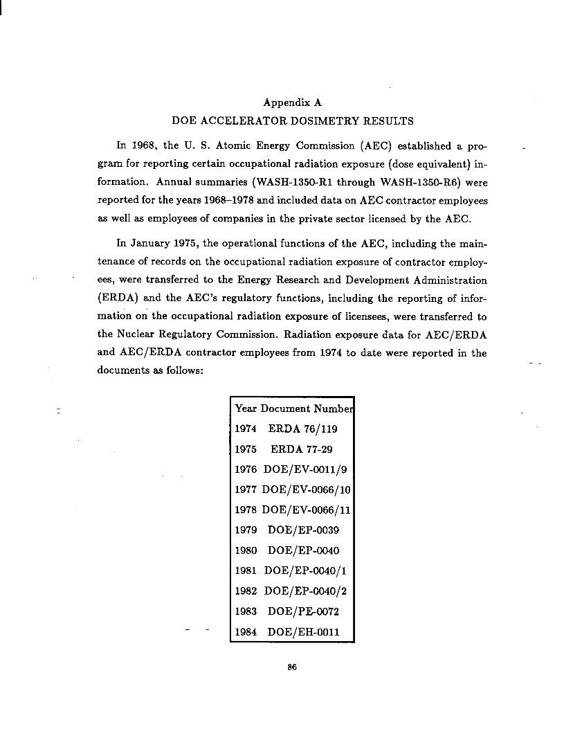
Appendix A
DOE ACCELERATOR DOS~ETRY RESULTS
h 1968, the U. S. Atomic Energy Commission (AEC) established a pr~ _
gram for reporting certain occupational radiation exposure (dose equivalent) in-
formation. Annual summaries (WASH-1350R1 through WASH-1350R6) were
reported for the years 1968–1978 and included data on AEC contractor employees
as well as employees of companies in the private sector licensed by the AEC.
In January 1975, the operational functions of the AEC, including the main-
tenance of records on the occupational radiation exposure of contractor employ-
ees, were transferred to the Energy Research and Development Administration
(ERDA) and the AEC’S regulatory functions, including the reporting of infor-
mation on the occupational radiation exposure of licensees, were transferred to
the Nuclear Regulatory Commission. Radiation exposure data for AEC/ERDA
and AEC/ERDA contractor employees from 1974 to date were reported in the
documents as follows:
Year Document Numbel
1974 ERDA 76/119
1975 ERDA 77-29
1976 DOE/EV-0011/9
1977 DoE/Ev-oo66/lo
1978 DOE/EV-0066/11
1979 DOE/EP-0039
1980 DOE/EP-0040
1981 DOE/EP-0040/l
1982 DOE/EP-0040/2
1983 DOE/PE-0072
1984 DOE/EH-0011
-.
86
Monitoring at DOE and DOE contractor facilities is required where the p-
tential exists for an individual to receive a dose or dose commitment in any
calendar quarter in excess of ten percent of the quarterly standards as prescribed
in DOE 5480.lA, Chapter 11.
Whole body radiation exposure reporting for accelerator facilities for the
years are tabulated in Table A-1. These results are compiled from the refer-
enced documents and are subject to some error due to different interpretation of
reporting codes. They are approximately right, however, and show the correct
trends. The data indicate that as time progresses, the dose equivalents have
been reduced. There are multiple reasons for this reduction, e.g., increasing op-
eration in storage ring mode rather than fixed target mode, financial restrictions
on operating time, improved design of components subject to failure, etc.
-–
-.
87
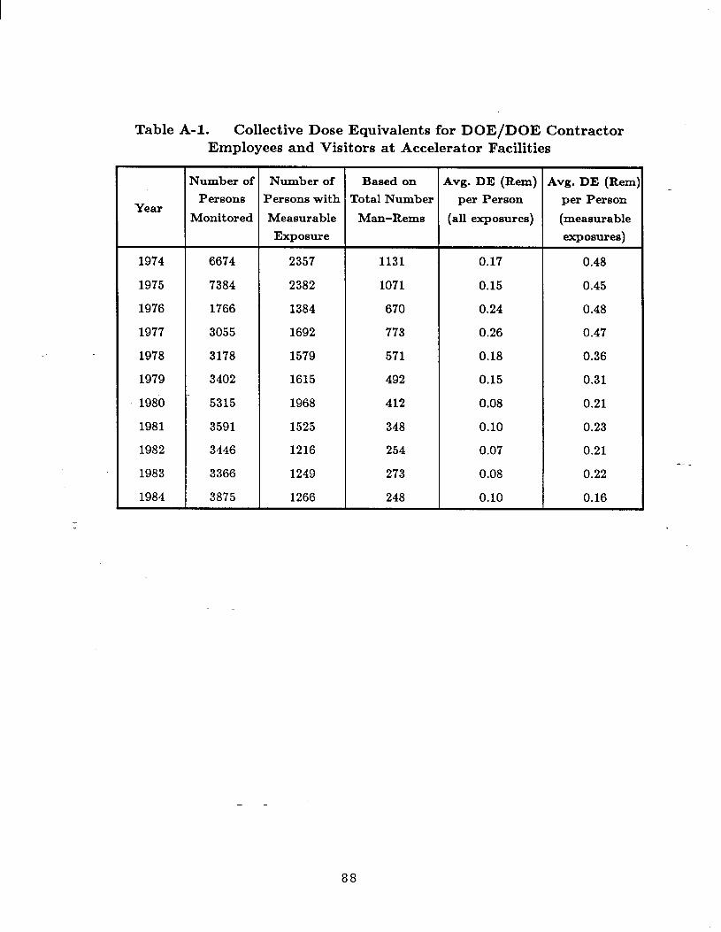
Table A-1. Collective Dose Equivalents for DOE/DOE Contractor
Employees and Visitors at Accelerator Facilities
Number of Number of Based on Avg. DE (Rem) Avg. DE (Rem)
Persons Persons with Total NumberYear
per Person per Person
Monitored Measurable Man–Reins (all exposures) (measurable
Exposure exposures)
1974 6674 2357 1131 0.17 0.48
1975 7384 2382 1071 0.15 0.45
1976 1766 1384 670 0.24 0.48
1977 3055 1692 773 0.26 0.47
1978 3178 1579 571 0.18 0.36
1979 3402 1615 492 0.15 0.31
1980 5315 1968 412 0.08 0.21
1981 3591 1525 348 0.10 0.23
1982 3446 1216 254 0.07 0.21
1983 3366 1249 273 0.08 0.22
1984 3875 1266 248 0.10 0.16
-.
88

Appendix B
SAFETY INTERLOCK REPORT
During the preparation of this manual, DOE requested that a sub-committee “
be formed to consider the safety aspects of using computers in safety interlock
systems. Their report is appended here u Appendix B. The report w= writ-
ten, circulated widely for comments, and revised to its present form. The sub-
committee composition is:
K. Crook, Chairman SLAC
S. Goldsmith SNL
W. Freeman FNL
A. McGeary BNL
COMPUTERS IN PERSONNEL SAFETY SYSTEMS
Computers for Accelerator Control and Monitoring
The use of digital computers in control systems for accelerators is now well
established. From the middle sixties, w the cost of computers came down and as
the reliability improved, computers were integrated into the control systems of
many accelerators. Initially, the primary application was status monitoring and
logging, but more recently the computer h= become a central element in the
control system itself, providing both digital and analog output signals that are
used to control beam-line devices along the accelerator. Today, the high reliability
of computer hardware, the sharp decrease in costs of computer components and
modules, coupled with the incre~ed complexity of the control requirements for
modern accelerators, make the choice of computer control highly desirable, if not
absolutely essential,
--
Computers For Personnel Safety Svstems
89

The use of computers in personnel safety systems h= been rare in large
accelerators built during the p~t ten years. Those responsible for the design of
safety systems tended to favor the conservative and proven technology that grew
out of railroad signaling systems, ship safety systems, and conventional power
plant technology. Most nuclear power plants designed over the l~t 30 years have
adopted this same safety system design approach—hardwired sensors and alarm
devices, coupled with electromechanical relay technology for the logic panels and
chassis.
More recently, some designers in both the nuclear and accelerator fields, have
replaced the relay logic panels with solid-state logic elements. This has been par-
ticularly true in c~es where the complexity of the logic requirements would have
required hundreds or even thousands of relays, or where the required response
time wu too f~t for relay circuits.
As confidence in the reliability of control computers increases there is mount-
ing interest in the use of computers in accelerator safety systems. By way of-“
comparison, in the normally conservative nuclear industry, digital-based systems
are now becoming prevalent even to the point where fully computerized shutdown .
systems will be installed in certain nuclear power plants starting in 1987 (Ref.
1).
In deciding between the relative merits of conventional relay systems versus
a solid-state or computer-b~ed approach, a primary concern of designers is the
fail-safe nature of the circuits. When power is lost, when a sensor becomes
disconnected, or a wire connection is broken, does the circuit or system fall back
to the safe condition?
For relays, an energized coil will reenergize, and its contacts will normally
open when coil voltage is lost or when the coil itself shorts or opens. Thus if all
relays in the chain are held energized for normal operating conditions, almost all
fault conditions such w breaking a wire or removing a connector will cause the--circuit to revert to the safe state.
90

In the case of solid-state or computer systems, the failure mode is much more
difficult to predict. Design techniques must be adopted that prevent damage
to solid state components from external transient noise sources prevalent in a
high energy accelerator environment. High reliability components, self-checking
curcuits, and redundancy are also important features in improving overall system
security.
It should be noted that there are designers who hold strong views that
computer-b~ed systems are not an appropriate choice for safety systems in-
volving life-threatening hazards. The sensitivity of solid state electronics in a
hostile electromagnetic environment ~ well as software reliability are issues that
cause concern.
While the committee m a whole is sensitive to these apprehensions, we recog-
nize that computer-based safety systems are already a fact of life in accelerators
today.
It is our intent in these recommendations to propose broad guidelines for
those designers who believe that computer systems are appropriate for their safety
system applications.
RECOMMENDATIONS
General
1. Computer-based systems should only be selected after careful consideration
of all the options. Examples of applications when computers might be
suitable include:
(a) If the complexity of the logic would
number of conventional relays.
(b) If speed of response higher than that
judged to be an important factor.--
result in an unreasonably large
achievable with relay systems is
(c) If operational flexibility is an important requirement.
91
It should be noted that a design approach using hard-wired solid state
logic may be a satisfactory alternative to the use of a computer system
for some applications.
2. Computer-based systems should be chosen for safety applications only if
professional, full-time staff are available for the system implementation.
This requirement applies to the design, construction, and maintenance
phases of the project, and is important for both the hardware and software
aspects of the system. The software design and implementation should only
be undertaken by those who are specialists in both software engineering and
sensor-b~ed industrial control systems. It is also essential that software
designers be familiar with all the operational aspects of the safety system.
Minimum Requirements
The following constitute the minimum requirements for the use of computers
in accelerator personnel safety systems.-.
Hardware
1. Computer-b~ed systems may be used for accelerator personnel safety as
long ~ it can be demonstrated that the use of a computer does not incre~e
the risk of an accident to an unacceptable level. The computer system, in-
cluding software, must have high reliability. At a minimum, the safety
system including the computer and its input/output devices should be de-
signed to have a MTBF of not less than 90,000 hours. Thus, if a monthly
service inspection were carried out, the system would be operational 99.2
percent of the time.
One method of improving reliability is to use completely redundant hardware–
two computers and associated 1/0. In some instances, triple redundancy
may be justified. Consideration may also be given to the use of the class--
of ‘ultra-high availability” fault tolerant computers which have internal
92

2.
3.
4.
built-in redundancy in both hardware and software. This latter approach
may only be adopted if it can be demonstrated that the reliability and
fault tolerance is at least as high as the independent, redundant hardware
approach.
For applications in typical accelerators, computers used for safety systems
must be dedicated to that function alone.
Programs written for computers used in safety systems should reside in
Read Only Memory (ROM) or Programmable Read Only Memory (PROM)
wherever feasible. If volatile memory must be used, it should have error
detection and correction features and it should have sufficient battery back-
up for long-term retention of the program state.
Watchdog timers should be incorporated so that action can be taken if the
program fails to reach appropriate checkpoints within a specified time.
Software
1. All programming must be undertaken by designated and authorized profes-
sionals using accepted methodology to insure software of the highest qual- “
ity. High modularity and testability must be incorporated in all software.
The emphmis must be directed toward writing fault tolerant programs.
Software hazard analysis should be performed wherever feasible. Accepted
techniques such M redundancy and checkpointing should be used.
Some suggested software standards are given in Refs. 2, 3, 4, and 5.
2. Program changes to meet new operational needs must be carefully con-
trolled using strict configuration management techniques. All changes must
be thoroughly tested, not only for the specific intended function that the
program change was meant to accomplish, but also for other unexpected
and unwanted effects in other parts of the program.--
3. In the approach where parallel independent computers are used to achieve
93
-“

reliability, consideration should be given to installing nonidentical but func-
tionally equivalent software to reduce common mode failure.
‘Testing
A computer-b~ed system must be thoroughly tested before being placed in
service, and at regular intervals thereafter. Testing must include all elements of
the system—the sensors, the computers, and the shutdown mechanisms, and must
be auditable with respect to description of tests, dates, and personnel performing
tests.
Operator Override
E computers are chosen for safety interlock applications, there should be, in
addition to the computer hardware and its connection to the shutoff equipment,
a separate independent operator (crash) override button on the console that
permits manual shutdown of the facility.-.
REFERENCES
1.
2.
3.
4.
5.
Control and Safety Computers in CANDU Power Stations, R.S. Gilbert,
IAEA Bulletin, Autumn 1985.
Standard for Quality Assurance Plans, ANSI/IEEE STD 730-1984.
Standard for Requirements Specification, ANSI/IEEE STD 8301983.
Standard for Software Test Documentation, IEEE STD 829-1983.
Standard for Software Configuration Plan, IEEE STD 828/1983.
-.
94

Appendix C
RECOMBINATION CALCULATIONS
-The following is an example of recombination calculations for a spherical air .
ionization chamber at STP.
a = 10 cm , b = 1 cm (outer and inner electrode radii, respectively)
collection potential (V) = 350 volts
accelerator pulse repetition rate = 100 Hz
average dose rate = 1 rad/h (0.01 Gy/h).
The collection efficiency, j, for a single beam pulse is given by the following
expression:
j = (1/u) in (1+ u)
-.
where
()U=pr $ ,
d = (a– b) KspH
r = Initial charge density per pulse —esu cm–3 (C m–3)
p = 1.005 x 10³ Vcm esu–1(3.02 x 10¹⁰ V m C–l) (ICRU82) .
Then the efficiency, j, is equal to 0.999.
The transit time, TsPH , is compared with the machine pulse repetition rate
to determine whether there will be an overlapping of pulses:
TSPH = (dKspH)2Vk ‘
95
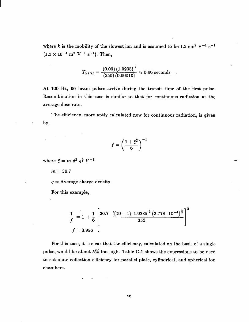
where k is the mobility of the slowest ion and is ~sumed to be 1.3 cm2 V–l s–]
(1.3 x 10⁻⁴ m2 V-l S-l). Then,
[(0.09) (1.9235)]2 ~ 066 seconds
‘SPH = (350) (0.00013) . .
At 100 Hz, 66 beam pulses arrive during the transit time of the first pulse.
Recombination in this case is similar to that for continuous radiation at the
average dose rate.
The efficiency, more aptly calculated now for continuous radiation, is given
by,
where ~ = m d2 q; V–l
()1+(2 -1
6
q = Average charge density.
For this example,
‘[2
1 36.7 [(10 – 1) 1.9235]2 (2.778 10-4)+
;=1+6
350 1j=0.956 .
—.
For this c~e, it is clear that the efficiency, calculated on the basis of a single
pulse, would be about 5% too high. Table C-1 shows the expressions to be used
to calculate collection efficiency for parallel plate, cylindrical, and spherical ion
chambers.
-.
96

Efficiency
Geometry Continuous t K Transit Time, T
Radiation
~ (1+:’~’)-1 ‘p1=md2q1’2 v-1Plane Tpl = d2/Vk
Parallel
(l+:’’Y1)-l
~~yl (a – b)2 q~~~Cylindrical
( )
a/b + 1 In a/b 1’2 [(a - b) ~cy/12
CCY1 = m (V/d) b ln(a/b)K,yl = TCyl = Vk
a/b–l 2
(l+:’’ph)-l
K~Ph (a – b)2 q~~~Spherical
CSph= ‘(V/d) (b/a) (a -b) Ksph= [:(:+1+:)11’2‘sph=[(a-:rph]
Appendix D
REGULATORY INFORMATION FOR DOE CONTRACTORS
-The Environmental Protection Agency (EPA) has the responsibility to de- -
velop radiation protection guidance for Federal agencies. This guidance is nor-
mally b=ed on recommendations of the International Commission on Radiation
Protection (ICRP) and the National Council on Radiation Protection and Mea-
surements (NCRP). The EPA guidance, upon approval of the President, is imple-
mented in the regulations of all federal agencies, including the Nuclear Regulatory
Commission (NRC) and the Department of Energy (DOE).
NRC does not license accelerator facilities. Some State agencies do; however,
if an accelerator facility is DOE-controlled (i.e., the buildings or grounds are
owned or le~ed by DOE), then an exemption from all radiological licensing
exists. DOE will then exercise statutory authority for radiological safety matters
by way of contractual requirements. Depending on other factors, DOE may even
have authority for the entire spectrum of safety at a given facility; this is the case—.
at most DOE national laboratories. In c~es where DOE does not control the
facility (in the above sense) and the local State agency has an adequate capability
for accelerator radiation protection matters, that agency will exercise authority.
-DOE authority (and responsibility) for safety at its contractor facilities is
of an overview nature. DOE conducts on-site appraisals and enforces compli-
ance with Federal guidance, DOE Orders, and specific consensus standards. The
contractor is responsible for day-t~day operational matters and normally re-
solves safety-related problems. However, employees may also approach DOE,
and eventually the Occupational Safety and Health Administration (O SHA), if
their concerns are not satisfied.
DOE radiation dose limit for individual members of the general public due
to the operation of a DOE facility is 500 mrem (5 mSv) in any year (DOE
5480. 1A, Chapter XI). For larger populations the radiation dose limit has been--
170 mrem/year (1.7 mSv). However, the draft revision of this chapter would
98
change this value to 100 mrem/year (1 mSv). In the interim, a memo from
William A. Vaughan, Asst. Secretary for Environment, Safety and Health, dated
August 5, 1985 has established the dose limit for any member of the public as
100’ mrem/year (effective July 1, 1985). An occasional annual exposure of 500 -
mrem/year (5 Smv) is still allowed. This same memo establishes a DOE admin-
istrative action level of 25 mrem/year (250 pSv/year) which would require an
investigation by the responsible DOE field office. Most of the DOE accelerators
try to hold the site boundary doses below about 10 mrem/year (100 pSv/year).
At present the occupational dose limits, as set by DOE 5480.lA Chapter XI,
are 5 rem/year (SO mSv/year). Planned revisions to the Order would establish
the limit m 5 rem effective dose equivalent consistent with the EPA Radiation
Protection Guidance to Federal Agencies for Occupational Exposures published
January 1987. For the purpose of keeping radiation exposures ALARA, the
design objective for new or modified facilities must be 20 percent of these limits.
The Federal Water Pollution Control Act, the Clean Air Act, and the Safe --
Drinking Water Act authorizes the EPA to set standards for the control of ra-
dioactivity in liquid effluent discharges, air emissions, and public drinking water
supplies, respectively. A m~imum of 4 rnrem/year (40 pSv/year) is the limit due
to radioactivity in community drinking water supplies. Similarly, 25 mrem/year
(250 ~Sv/year) is the limit due to radioactivity rele~ed into the air. This limit
of 25 mrem/year -(250 #Sv/year), with a reporting level at 12.5 mrem/year (125
pSv/year), for exposures to the general public from radioactivity relemed in the
air was promulgated to DOE contractors in the earlier referenced William A.
Vaughan memo. In most cues, state environmental protection agencies have
enforcement powers. However, the Federal EPA has authority to enforce the
regulations if a state fails to act.
The following is a list of DOE Orders applicable to radiation safety at ac-
celerators. Specific requirements will in each case be promulgated by the DOE
Contracting OfficW. -
99
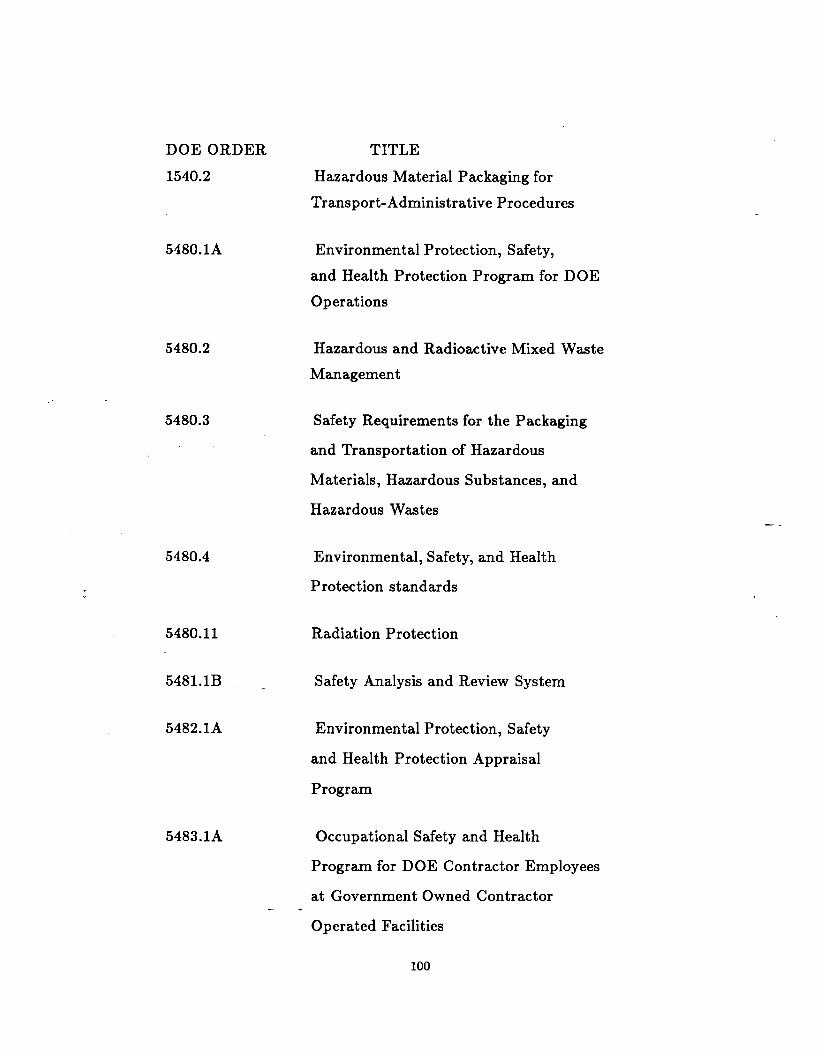
DOE ORDER TITLE
1540.2 Hazardous Material Packaging for
Transport-Administrative Procedures
5480.lA Environmental Protection, Safety,
and Health Protection Program fol
Operations
5480.2 Hazardous and Radioactive Mixed
Management
DOE
W-te
5480.3 Safety Requirements for the Packaging
and Transportation of Hazardous
Materials, Hazardous Substances, and
Hazardous Wastes
5480.4 Environmental, Safety, and Health
Protection standards
5480.11 Radiation Protection
5481.lB Safety Analysis and Review System
5482.1A Environmental Protection, Safety
and Health Protection Appraisal
Program
5483.1A Occupational Safety and Health
Program for DOE Contractor Employees
at Government Owned Contractor--
Operated Facilities
-.
100

5484.1 Environmental Protection, Safety
and Health Protection Information
Reporting Requirements
5500.2 Emergency Planning, Preparedness,
and Response for Operations
5820.2 Radioactive Wrote Management
6430.lA General Design Criteria
—.
-.
101
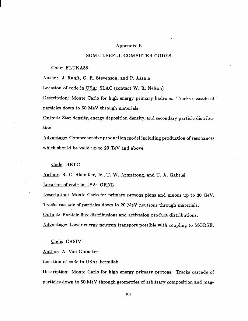
Appendix E
SOME USEFUL COMPUTER CODES
‘Code. FLUKA86— .
Author: J. Ranft, G. R. Stevenson, and P. Aarnio
Location of code in USA: SLAC (contact W. R. Nelson)
Description: Monte Carlo for high energy primary hadrons. Tracks cascade of
particles down to 50 MeV through materials.
Output: Star density, energy deposition density, and secondary particle distribu-
tion.
Advantage: Comprehensive production model including production of resonances
which should be valid up to 20 TeV and above.
—.
Code. HETC— .
Author: R. C. Alsmiller, Jr., T. W. Armstrong, and T. A. Gabriel
Location of code in USA: ORNL
Description: Monte Carlo for primary protons pions and muons up to 30 GeV.
Tracks cascade of particles down to 20 MeV neutrons through materials.
Output: Particle flux distributions and activation product distributions.
Advantage: Lower energy neutron transport possible with coupling to MORSE.
Code. CASIM— .
Author: A. Van Ginneken
Location of code in USA: Fermilab
Description: Monte Carlo for high energy primary protons. Tracks cascade of--
particles down to 50 MeV through geometries of arbitrary composition and mag-
102

netic fields. CASIMU Version tracks muon
subroutine follows electromagnet ic showers.
Output: Star and energy density contours.
generated by the cascade. AEGIS
Advantage: kteraction processes during transport permit tracking of 20 TeV
and primaries weighting techniques greatly reduce computer running times.
Code” MORSE— .
Author: M. B. Emmett
Location of code in USA: RSIC (ORNL)
Description: Monte Carlo for transport of neutrons with energies from thermal
to 20 MeV up to 400 MeV with available cross sections), and photons to 14 MeV.
Output: Fluences, dose for any given response.
Advantage: Thre~dimensional.
Code. EGS4— .
Author: W. R. Nelson, H. Hirayama, and David W. O. Rogers
Location of code in USA: SLAC
Description: Monte Carlo for electrons-photons in the range of 10 TeV down to
few tens of KeV.
Output: Particle flux distributions, energy deposition, etc.
Advantage: Very well-understood QED processes. Numerous benchmark exam-
ples.
—.
Code: ITS (Integrated Tiger Series)
Author: J. A. Halbleib and T. A. Melhorn--
Location of Code in USA: R. S.I.C. or Sandia National Laboratories
103
Description: Time-independent Monte Carlo for coupled electron/photon radia-
tion transport from 1.0 keV to 1.0 GeV with or without the presence of macro-
scopic electric or magnetic fields. Slab, spherical, cylindrical, or combinatorial -
geometries.
Output: Electron and photon fluences, energy and charge deposition.
Advantages: User friendly but rigorous. Runs on Cray, IBM, V=, and CDC.
Code: ANISN-W
Author: Westinghouse
Location of Code in USA: R. S.I.C.
Description: An old, but useful multigroup one-dimensional time-independent
discrete ordinates transport code for neutrons and photons less than 20 MeV.-.
Output: Neutron and photon fluences, fission rate, dose rates, and activation
through ‘activities.”
Advantages: Well-proven and widely implemented. Runs fast.
Code. DOT4-— .
Author: ORNL
Location of Code in the USA: R. S.I.C,
Description: Multigroup tw~dimensional time-independent discrete-ordinates
transport code for neutrons and photons less than 20 MeV.
Output: Neutron and photon fluences.
Advantages: May converge sooner than Monte Carlo for two-dimensional prob---
lems.
104

Code: OneDant
Author: LANL
Location of Code in the USA: R. S.I.C.
Description: Multigroup on~dimensional time-independent
transport code for neutrons and photons less than 20 MeV.
Output: Neutron and photon fluences.
discrete-ordinates
Advantages: May converge sooner than Monte Carlo for one-dimensional
Iems.
Code: TwoDant
Author: LANL
Location of Code in the USA: R. S.I.C.
Description: Multigroup two-dimensional time-independent
transport code for neutrons and photons less than 20 MeV.
Output: Neutron and photon fluences.
prob-
—.
discrete-ordinates
Advantages: May converge sooner than Monte Carlo for two-dimensional prob-
lems.
-.
105
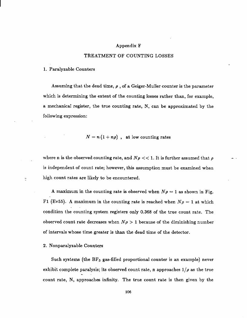
Appendix F
TREATMENT OF COUNTING LOSSES
1. Paralyzable Counters
Assuming that the dead time, p , of a Geiger-Muller counter is the parameter
which is determining the extent of the counting losses rather than, for example,
a mechanical register, the true counting rate, N, can be approximated by the
following expression:
N=n(l+np) , at low counting rates
where n is the observed counting rate, and Np << 1. It is further assumed that p -–“
is independent of count rate; however, this assumption must be examined when
high count rates are likely to be encountered.
A maximum in the counting rate is observed when Np = 1 as shown in Fig.
F1 (Ev55). A maximum in the counting rate is reached when Np = 1 at which
condition the counting system registers only 0.368 of the true count rate. The
observed count rate decreases when Np > 1 because of the diminishing number
of intervals whose time greater is than the dead time of the detector.
2. Nonparalyzable Counters
Such systems (the BF3 g~-filled proportional counter is an example) never
exhibit complete paralysis; its observed count rate, n approaches l/p as the true--
count rate, N, approaches infinity. The true count rate is then given by the
106

expression
N= nI–rip
where p is the pulse pair resolution time of the counting system.
1.0’ 4 I i I 1 I I 1 I I i I 1 1 ) 1 I I I
np
0,5.k
oo~’ I 1 ! ) ! ! t 1 I 1 1 t I ! I 1 1 1 I
0.5 1.0 1.5 2.0--Np
Fig. F1. ( This figure is reproduced from EV55 by permission of McGraw-Hill Book Co.)
-.
107

3. Dead Time Losses for Pulsed Sources (Kn87)
Assumed Source:
ON
l/F T
OFF
TIME
Fig. F2
Let:
T = Source pulse length
~ = Source pulse frequency
~ = Resolving time of detector system
m = observed counting rate
~ = True countingrate(if r were O)
We will only address the c=e when:
T< T<(l/f– T) .
(Then one can have a mmimum of one count per source pulse, or m < ~, always.
Also, the detector will be fully recovered at the start of each source pulse.)--
Then:
108
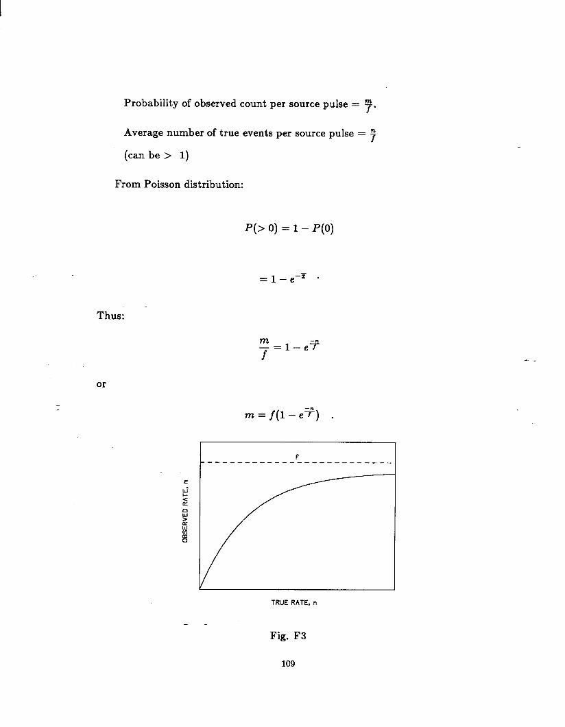
of observed count per source pulse = ~.
Average number oftrueevents per source pulse= ~
(can be> 1)
From Poisson distribution:
F(> o) = 1 – P(o)
=l_e–T .
Thus:
m_=l–e~f
~=f(l–e%) .
I F---— —--— ____ ____ ____ ____ _
TRUE RATE, n
-.
-.
Fig. F3
109

We are more often interested in solving for n to provide a correction formula:
()
j‘=jln ~ “
Note that under these conditions, neither the length of the resolving time r
nor the detailed dead-time behavior of the system (e.g., whether it iS Paralyzable)
have any effect on the correction.
-.
-.
110
References
AC162 American Concrete Institute, 1962, Concrete for Radiation
Shieldinq, Compilation No. 1 (Detroit MI: American Concrete
Institute).
Ak63 Akagi H.
around human
Health Phys.
A172 Alder K.,
Proc. Heavy
and Lehman R. , 1963, “Neutron dosimetry in and
phantoms by the use of nuclear track emulsion,”
9, 207.
1972, “Coulomb interactions with heavy ions,” in
Ion Sumer Study ORNL, Conf.–72O669, Distribution
Category UC–34 (Springfield, VA: National Technical
Information Services).
An63a Andersson I. O. and Braun J. , 1963, “A neutron rem
counter, “ Nukleonik 6, 237.
An63b Andersson I. O. and Braun J., 1963, “A neutron rem counter ‘-
with uniform sensitivity from 0.025 MeV to 10 MeV,” in: Proc.
Symp. on Neutron Detection, Dosimetry and Standardization,
STI/PUB/69 (Vienna: International Atomic Energy Agency)>
_Harwell, England.
ANS166 American National Standard Institute, 1966, Practice for
Occupational Radiation Exposure Records Systems, ANSI
N13.6–1966(R 1972) (New York ANSI).
ANS172 American National Standards Institute, 1972,
Specification for Accident Prevention Siqns, ANSI Z35.1–1972
(New York ANSI).
-. 111
ANS178 American National Standards Institute, 1978, Radiological
Safety in the Desiqn and Operation of Particle Accelerators,
ANSI 43.1 (Washington, DC: U.S. Government Printing Office).
Aw71 Awschalom M. , Howe H. , Schamber F., and Shafer R. , 1971, .
“Radiation monitoring at NW: instruments and systems,” Proc.
of Int. Conqress on Protection Aqainst Accelerator and Space
Radiation, Volume II p 1035, European Organization for Nuclear
Research, CERN, Geneva, Switzerland, CERN 71–16.
Ba66 Barbier M., Hutton A. and Pasinetti A., 1966, Radioactivity
Induced in Tissues by 600 MeV Protons, CERN , Geneva,
Switzerland, CERN 66–34.
Ba68 Babcock G., Breymayer K. E., Busick D. D., Crook K.,
Jenkins T. M., Mallory K. B., McCall R. C., Reagan D. D., and
Warren G. , 1968, “Protection systems,” in: The Stanford-.
~o–Mile Accelerator, (edited by R. B. Neal), 775-819 (New
York: W. A. Benjamin, Inc.)
Ba69a Barbier M., 1969, Induced Radioactivity (Amsterdam: North “
Holland Publishing Company).
Ba69b Baum J. W., Woodcock R. C. and Kuehner A. V. , 1969,
“Factor-s ‘affecting pulse size in sealed tissue equivalent
counters,” in: Proc. 2nd Int. Conf. on Accelerator Dosimetry
and Experience, USAEC CONF–6911O1 p 648 (Stanford, CA: United
States Atomic Energy Commission).
Ba75 Baker S. I., 1975, “Soil activation measurements at
Fermilab,” in: Proc. Third Environmental Protection
-- 112

Conference, Volume I, p 329, ERDA–92 (Washington, D. C. : U.
S. Energy Research and Development Administration).
Ba76 Batisti R., Bossart S., Schonbacher H. and Van de Voorde
.M., 1976, “Radiation damage to electronic components,” Nucl. .
Instrum. Methods 136, 451.
Ba85 Baker S. I., 1985, “Fermilab soil activation experience,”
in: Proc. Fifth DOE Environmental Protection Information
Meetinq, Vol. 2 p 673 CONF–841187 (Washington, D. C.: U. S.
Department of Energy).
Ba86 Baker S. I., 1986, Site Environmental Report for Calendar
Year 1985, Fermi National Accelerator Laboratory, Batavia, IL
60510, Fermilab Report 86/37.
Be82 Beynel P., Maier P. and Schonbacher H. , 1982, “Materials
used around high–energy accelerators,” in: Compilation of—=
Radiation Damaqe Test Data, Part 111, European Organization
for Nuclear Research, CERN, Geneva, Switzerland, CERN 82 – 10.
Bi69 Birchall I., 1969, “Gamma scatter from open top cells,” “
Health Phys. 16, 47.
B066 Boag J. W., 1966, “Ionization chambers,” in: Radiation
Dosimet-ry Volume II (edited by Frank H. Attix and William C.
Roesch), pp. 2–72 (New York: Academic Press).
B072 Borak T. B., Awschalom M., Fairman W., Iwami F., and Sedlet
J ., 1972, “The underground migration of radionuclides produced
in soil near high energy proton accelerators,” Health Phys.
23, 679.
-- 113
B075 Borak T., 1975, “A simple approach to calculating gamma ray
SKYSHINE for reduced shielding applications,” Health Phys.,
29, 423.
B085 Bouquet F. and Winslow J., 1985, Radiation Data for Desiqn .
and Qualification of Nuclear Plant Equipment, Electric Power
Research Institute, EPRI NP–4172 (Palo Alto, CA: EPRI ).
Br81 Bruce M. B. and Davis M. V. , 1981, Radiation Effects on
Orqanic Materials in Nuclear Plants, Electric Power Research
Institute, EPRI NP–2129 (Palo Alto, CA: EPRI )
Bu72 Busick D. and Warren G., 1972, “Tungsten-181 contamination
incident, “ in Health Physics Operational Monitoring, vol. 2
(edited by C. A. Willis and J. S. Handloser) pp. 1281 - 1289
(New York: Gordon & Bresch).
Ce83 Cetier H., 1983, Introduction to Health Physics (Second-.
Edition) (New York: Pergamon Press).
CEBAF87 Continuous Electron Beam Accelerator Facility, 1987,
TN–0061 (Virginia: CEBAF ).
CFR83a Code of Federal Regulations, 1983, “Standards for
Protection Against Radiation”, 10 CFR 20 (Washington, D. C:
Office ‘of ‘the Federal Register).
CFR83b Code of Federal Regulations, 1983 “Transportation”, 49CFR
(Washington, D. C: Office of the Federal Register).
CFR85 Code of Federal Regulations, 1985, “Environmental
Protection Agency,” 40 CFR 141 (Washington, D. C.: Office of
The Federal Register).
-. 114
CFR86 Code of
Commission, “
(Washington,
C183 Clapier F.
Federal Regulations, 1986, “Nuclear Regulatory
10 CFR 20 Draft, Federal Register 51, Jan
D.C.: Office of the Federal Register).
and Zoidins C. S., 1983, “Neutron dose
lent rates due to heavy ion beams,” Nucl. Instrum.
217, 489–494.
C053 Cowan F. P. and Handloser J. S. , 1953, Health
9, 1986
equiva– .
Methods
Physics
Proqram for the Brookhaven Cosmotron, Brookhaven National
Laboratory, Upton, NY 11973, BNL 264 (T–43).
C082 Cossairt J. D., Mokhov N. V., and Murphy C. T. , 1982,
“Absorbed dose measurements external to thick shielding at a
high”energy proton accelerator: Comparison with Monte–Carlo
calculations,” Nucl. Instrum. Methods. 197, 465.
C085 Cossairt J. D. and Coulson L. V. , 1985, “Neutron skyshine-.
measurements at Fermilab,” Health Phys. 48, 175.
De68 De Staebler H., Jenkins T. M., and Nelson W. R., 1968,
“Shielding and Radiation,” in The Stanford Two-Mile
Accelerator, (edited by R. B. Neal), pp 1029–1064 (New York:
W. A. Benjamin Inc.).
De85 Denis J-.A. and Dunster H. J., 1985, “Radiation quality and
radiation protection: Implications of changes in quality fac–
tors,” Rad. Prot, Dosim. 13, 327.
Di73 Distenfeld C. H., Colvett R. D. and Ash J. A., 1973,
Evaluation of Accidental Exposure to Accelerator Personnel,
Brookhaven National Laboratory, Upton, N. Y. BNL 17796.
-. 115

DOE80 Department of Energy, 1980, A Guide to Reducinq Radiation
Exposure to as low as Reasonably Achievable (ALARA) ,
DOE/EV/1830-T5 (Springfield, VA: National Technical Information
.Service).
DOE86 Department of Energy, 1986, DOE Standard for the
Performance Testinq of Personnel Dosimeters, DOE/EH–0027
(Washington, D. C.)
EL86 Elder J. C., Graf J. M., Dewart J. M., Buhl T. E., Wenzel
W. J., Walker L. J. and Stoker A. K. , 1986, A Guide to
Radiological Accident Considerations for Sitinq and Desiqn of
DOE Nonreactor Nuclear Facilities, Los Alamos National
Laboratory, LA-10294-MS (Los Alamos, NM).
ERDA76 U. S. Energy Research & Development Administration, 1976,
Nuclear Air Cleaninq Handbook, ERDA Publication 76–21-.
(Springfield, Va: National Technical Information Service).
Ev55 Evans R. D., 1955, The Atomic Nucleus (New York: McGraw
Hill ).
Gi68 Gilbert W. S., Keefe D., McCaslin J. B., Patterson H. W.,
Smith A. R., Stephens L. D., shaw K. B., Stevenson G. R.,
Thomas ‘R.- H., Fortune R. D., and Goebel K., 1968,
CERN–LRL–RHEL Shieldinq Experiment at the CERN Proton
Synchrotron, Lawrence Berkeley Laboratory, Berkeley, CA
94720, UCRL–17941.
Gi81 Gibson T. A., Ozaki C. B., and Becker J. F., 1981, “The
health physics hazards of x–rays
wave waveguides, ” Health Physics
-- 116
produced by evacuated micro–
40, 893.
G068 Goodman L. J. and Rossi M. N., 1968, “The measurement of
dose equivalent using paired ionization chambers,” Health
= 14, 168.
G076 Gollon P. J., 1976, “The production of radioactivity by .
accelerators,” IEEE Trans. Nucl. Sci. NS–23(4), 1395.
G078 Gollon P. J., 1978, Soil Activation Calculations for the
Anti–Proton Tarqet Area, Fermi National Accelerator
Laboratory, Batavia, IL. 60510, TM–816.
G085 Gover James E. and Srour Joseph R., 1985, Basic Radiation
Effects in Nuclear Power Electronics Technology, Sandia
National Laboratories, Albuquerque, NM 87185, SAND85–0776.
Gr87 Greenhouse N. A., deCastro T. M., Hankins D. E., McCaslin
J. B., Smith A. R., and Sun R. K., “An evaluation of NTA film
in an accelerator environment and comparison with CR–39,” sub–—.
mitted to Radiat. Prot. Dosim.
Ha83 Harrell J. A., Manke P. L. and Gover J. E. , 1983, The
Application of Remote Electronics in a Nuclear Fuel “
Reprocessing Environment: Radiation Effects and Desiqn
Guidelines, Sandia National Laboratories, Albuquerque,
87185, SAND82-2151.
H072 Hofert M., 1972, “Dose equivalent and quality factor
NM
of
radiation from high–energy accelerators, “ in: Proc. 1st Symp.
on Neutron Dosimetry in Bioloqy and Medicine~ EUR 4896 d–f–e
(Munchen: EURATOM).
-. 117
H075 Hofert M., 1975, A Comparison of Dose Equivalent
Measurements Around a GeV Proton Accelerator, European
Organization for Nuclear Research, CERN, Geneva, Switzerland,
.Internal Rep. DI/HP/187.
H084 Hofert M. and Stevenson G. R., 1984, “Dose equivalent meas–
urement around GeV accelerators, “ Radiat. Prot. Dosim. 9,
235.
Hu60 Hubbard
production
E. L., Main R. M., and Pyle R. V., 1960, “Neutron
by heavy ion bombardments,” Phys. Rev. 118, 507.
IAEA79 International Atomic Energy Agency, 1979, Radiological
Safety Aspects of the Operation of Electron Linear
Accelerators, Tech. Report Series No. 188 (written by W. P.
Swanson) (Vienna: IAEA ).
IAEA89 International Atomic Energy Agency, 1989, Radiological—.
Safety Aspects of the Operation of Proton Accelerators, Tech.
Report Series No. XXX (written by R. H. Thomas and G. R.
Stevenson) (Vienna: IAEA).
ICRP82 International Comission on Radiation Protection, 1982,
“Cost-Benefit Analysis in the Optimization of Radiation
Protect-ion-,“ ICRP Publication 37 (Oxford: Pergamon Press).
ICRU78 International Commission on Radiation Units and
Measurements, 1978, “Basic Aspects of High Energy Particle
Interactions and Radiation Dosimetry,” ICRU Report 28
(Washington, D. C.: ICRU).
-. 118

ICRU82 International Commission on Radiation Units and
Measurements, 1982, “The Dosimetry of Pulsed Radiation,” ICRU
Report 34 (Washington, D. C. : ICRU) .
ICRU85 International Commission on Radiation Units and .
Measurements, 1985, “Determination of Dose Equivalent
Resulting from External Radiation Sources,” ICRU Report 39
(Washington, D. C.: ICRU).
ICRU86 International Commission on Radiation Units and
Measurements, 1986, “The Quality Factor in Radiation
Protection ,“ ICRU Report 40 (Washington, D. C. : ICRU) .
In84 Ing H., McCall R. C., Jenkins T. M. and Warren G. J. ,
1984, “Identification of neutrons from the cooling water of a
GeV electron accelerator,” Nucl. Instrum. Methods 219, 41.
1s68 Islitzer N.F. and Slade D.H., “Diffusion and transport—.
experiments,” in: Meteorology and Atomic Enerqy –1968, (edited
by D.H. Slade), U.S. Atomic Energy Commission, TID–24190
(Springfield, VA: Clearinghouse for Federal Scientific and
Technical Information).
Ja68 Jaeger R. G., Editor–in–Chief, 1968–1970, Enqineerinq
Compendium on Radiation Shieldinq, Vols . 1–3 , (New York:
Springer–Verlag ).
Je64 Jenkins T. M., 1964, Private communications.
Je68 Jenkins T. M. and McCall R. C., 1968, Emerqency
Determination of Dose Equivalent in Hiqh Enerqy Accelerator
Accidents, Stanford Linear Accelerator Center, Stanford, CA
94309 SLAC–PUB–447.
-- 119

Je70 Jenkins T. M., Busick D. D., McCall R. C., Nelson W. R.,
Svensson G. K., Warren G. J., Baumgarten A., Harris J. L.,
Murray J. J., Seppi E. J., and Vetterlein R. J. , 1970,
.“Beam-safety considerations at the Stanford Linear Accelerator .
Center,” Nuclear Safety 11, 435.
Je74 Jenkins T. M., 1974, “Accelerator boundary doses and skysh–
ine, “ Health Physics 27, 251.
Je79 Jenkins T. M., 1979, “Neutron and photon
through concrete from a 15 GeV electron beam in a
measurements
target– com–
parison with models and calculations,” Nucl. Instrum. Methods
159, 265.
Je86 Jenkins T.M., 1986, in CEBAF Workshop on Radiation Safety,
Newport News, VA April 7–9 (to be published).
J067 Joffre H. and Vialettes H. , 1967, “Review of accidental—.
irradiations with accelerators and protective measures against
radiation,” in: Proc. Symp. on Accidental Irradiation at
Place of Work, EUR–3666, CONF–660412, (Nice, France: EURATOM). “
Ki64 Kircher J. F. and Bowman R. E. , 1964, Effects of Radiation
on Materials and Components (New York: Reinhold Publishing
Corporation) .
Kn87 Knoll G. F., private communication.
K065 Komochkov M. M., 1965, Estimation of the Dose from
Accidental Irradiation by a Larqe Amount of Hiqh–Enerqy
Particles CERN, Geneva, Switzerland, CERN–Trans. 66–5,
Original JINR Report P2008.
-. 120

Ku73a Kuehner A. V., Chester J. D., and Baum J. W., 1973,
“Portable mixed radiation dose–equivalent meter,” in: Proc.
Symp. on Neutron Monitoring for Radiation Protection Purposes,
.Vol. 1 (Vienna: International Atomic Energy Agency).
Ku73b Kuehner A. V. and Chester J. D., 1973, Dose Equivalent
Meter Operatinq Instructions, Brookhaven National Laboratory,
Upton, NY 11973, BNL , Health and Safety Division, Informal
Report.
Kr79 Kraner H. W., 1979, Fast Neutron Damaqe in Germanium
Detectors, Brookhaven National Laboratory, Upton, NY 11973,
BNL–26850.
Kr81 Kraner H. W., 1981, Radiation Damaqe in Semiconductor
Detectors, Brookhaven National Laboratory, Upton, NY 11973,
BNL–30616.-—.
La65 Lanzl Lawrence H., Rozenfeld Martin L., and Tarlov Alvin
R ./ 1965, “High-dose human exposure from a 10 MeV linear
accelerator,” in: Proc. 1st Symp. on Accelerator Radiation ~
Dosimetry and Experience, USAEC CONF–6511O9 (Brookhaven
National Laboratory , N. Y: United States Atomic Energy
Commiss-ion-).
La75 Lambert K. P., Schonbacher H. and Van de Voorde M., 1975,
“A comparison of the radiation damage of electronic components
irradiated in different radiation fields,” Nucl. Instrum.
Methods 130, 291.
121

La86 Lazarus D.M., 1986, Particle production and tarqetinq
experience, Brookhaven National Laboratory, Upton, New York
11973, BNL 38307.
Le64 Lehman R.,
neutrons from
Le65 Legeay G.,
De Kerviler H.
protons de haute
les tissus,” in
and Fekula O. M. 1964, “Energy spectrum of stray .
the bevatron,” Nucleonics 22 (11), 35.
Court L., Prat L., Jeanmaire L., Daburon M. L.,
and Tardy–Joubert P. , 1965, “Dosimetrie des
energie par measure de beryllium–7 forme clans
Proc. of Conf. Personnel Dosimetry for
Radiation Accidents, IAEA, Vienna.
Le68 Leake J. W., 1968, “An improved spherical dose equivalent
neutron detector,” Nucl. Instrum. Methods 63, 329.
Li73 Lim C. B., 1973, The Development of a Neutron Spectrometer
using Multi–wire Spark Chambers, Ph.D. Thesis, Nuclear-.
Engineering Department, University of California, Lawrence
Berkeley Laboratory, Internal Report LBL–1719.
Li85 Liptak G. and Schuler R. , 1985, Radiation Tests on Selected
Electrical Insulating Materials for Hiqh–Power and Hiqh
Voltaqe Application, European Organization for Nuclear
Research, CERN, Geneva, Switzerland, CERN 85–02.
L086 Loew G. A., 1986, Some Issues Involved in Desiqninq a 1 TeV
(cm.) e+/– Linear Collider Usinq Conventional Technology,
Stanford Linear Accelerator Center, Stanford, CA 94305,
SLAC-3892
-. 122

Ma73 Madey R. and Waterman F. M. , 1973, “Neutron spectroscopy
from 1 MeV to 1 GeV,” in: Symp. on Neutron Monitoring for
Radiation Protection Purposes, Vol. 1 (Vienna: International
Atomic Energy Agency).
Ma74 Mamont–Ciesla K. and Rindi A. , 1970, Spark Chatier Neutron
and Proton Spectrometer – First Report on Performance,
Lawrence Berkeley Laboratory, Berkeley, CA 94720, LBL–3343.
Mc60 McCaslin J. B., 1960, “A high energy neutron flux detec–
tor, “ Health Phys. 2, 399.
Mc81 McCaslin J. B. and Thomas R. H., 1981. “Practical neutron
dosimetry at high–energies,” in: Proc. Seminar on Radiation
Protection Quantities for External Exposure, EUR–7101–EN
(Harwood Academic Press).
Mc85 McCaslin J. B., LaPlant P. R., Smith A. R., Swanson W. P.,-“
and Thomas R. H., 1985, “Neutron production by Ne and Si ions
on a thick Cu target at 670 MeV.A with application to radia–
tion protection, ” IEEE Trans. Nucl. Sci. NS–32(5).
Mc87 McCaslin J. B., Swanson W. P., and Thomas R. H., 1987,
“Moyer model approximations for point and extended beam
lossesj” Nucl. Instrum. Methods A256, 418.
Mi72 Miller A. J. and Patterson H. W., 1972, “Measurement of
induced activity to estimate personnel radiation exposures
received from accelerator beams,” Health Phys. 23, 671.
Mo79 Moore R. E., Baes III C. F., McDowell–Boyer L. M., Watson
A. P.r Hoffman F. O., Pleasant J. C., and Miller C. W., 1979,
-- 123

AIRDOS–EPA: A Computerized Methodology for Estimating environ–
mental Concentrations and Dose to Man from Airborne Releases
of Radionuclides, Oak Ridge National Laboratory, Oak Ridge, TN
.37830 ORNL–5532.
M081 Moe H. J., 1981, “Contact or near contact external dose
estimates, “ presented as Continuing Education at Health
Physics Society Annual Meeting, Louisville, KY.
M085 Moe H. J., 1985, “Radiation fields from extended sources,”
presented in Professional Enrichment Proqram at Health Physics
Society Annual Meeting, Chicago, 11.
Na72 Nachtigall D. and Burger G., 1972, “Dose equivalent deter–
mination in neutron fields by means of moderator techniques,”
in: Topics in Radiation Dosimetry, Supplement 1 (edited by F.
H. Attix) (New York: Academic Press).
NCRP76 National Council on Radiation Protection and
Measurements, 1976, “Structural Shielding Design and
Evaluation for Medical Use of X–Rays and Gamma Rays of
Energies up to 10 MeV”, NCRP Report No. 49 (Bethesda, MD:
NCRP ).
NCRP77 ~at-ional Council on Radiation Protection and
Measurements, 1977, “Radiation Protection Design Guidelines
for 0.1–100 MeV Particle Accelerator Facilities”, NCRP Report
No. 51 (Bethesda, MD: NCRP).
NCRP84 National Council on Radiation Protection and
Measurements, 1984, “Neutron Contamination from Medical
-.
-. 124
Electron Accelerators”, NCRP Report No. 79
NCRP ).
NCRP85a National Council on Radiation
(Bethesda, ~:
Protection and
.Measurements, 1985, “A Handbook on Radioactivity Measurements .
Procedures ,“ NCRP Report No. 58 2nd Edition (Bethesda, ~:
NCRP ).
NCRP85b National Council on Radiation Protection and
Measurements, 1985, “Management of Persons Accidentally
Contaminated with Radionuclides”, NCRP Report No. 65
(Bethesda, ~: NCRP).
NCRP86 National Council on Radiation Protection and
Measurements, 1986, “Radiation Alarms and Access Control
Systems,” NCRP Report No. 88 (Bethesda, MD: NCRP).
NCRP87 National Council on Radiation Protection and—.
Measurements, 1987, “Recommendations on Limits for Exposure to
Ionizing Radiation,” NCRP Report No. 91 (Bethesda, ~: NCRP).
Ne76 Nelson W. R. and Jenkins T. M. , “Similarities among the “
radiation fields at different types of high energy accelera–
tors, “ 1976, IEEE Trans. Nucl. Sci. NS–23, 1351.
Ne80 Nelson W. R. and Jenkins T. M. , Editors, 1980 Computer
Techniques on Radiation Transport and Dosimetry, (New York:
Plenum Press).
NRC74 u. s. Nuclear Regulatory Commission, 1974, “Termination
of Operating Licences for Nuclear Reactors,” U.S. NRC
Regulatory Guide 1.86 (Washington, D.C.: U.S. NRC).
-. 125

NRC 86 National Research Council, 1986, Preservation of
Historical Records, National Academy Press, Washington D. C.
Oh80 Ohnesorge W. F., Butler H. M., Fulmer C. M., and Mosku S.
.W., 1980, “Heavy ion target area fast neutron dose equivalent .
rates, “ Health Phys., 39, 633–636.
0p79 Opelka J. H., Mundis R. L., Mariner G. J., Peterson J. M.,
Siskind B., and Kikta M. J., 1979, Particle Accelerator
Decommissioning Argonne National Laboratory, Argonne, IL
60510 ANL/ES–82.
Pa69 Patterson H. W., Heckman H. H. and Routti J. T., 1969, “New
measurement of star production in nuclear emulsions and appli–
cations to high–energy neutron spectroscopy,” in: 2nd Int.
Conference on Accelerator Dosimetry and Experience, Conf.
691101 (Stanford, CA: United States Atomic Energy-.
Commission).
Pa73 Patterson H. W. and Thomas R. H., 1973, Accelerator Health
Physics (New York: Academic Press).
Pa76 Pasquill F., 1976, Atmospheric Dispersion Parameters in
-Graussian Plume modelinq part II. Possible requirements for
chanqe in the Turner Workbook Values, U. S. Environmental
Protection Agency EPA–600/4–76–030b. (Springfield, VA:
National Technical Information service).
Ph81 Phillips D. C., Scott J. M., Goebel K., Schonbacher H.,
Dieterle W., Eichenberger W., and Maurer J. , 1981, The
Selection and Properties of Epoxide Resins Used for the
-- 126
Insulation of Maqnet Systems in Radiation Environments,
European Organization for Nuclear Research, CERN , Geneva,
Switzerland, CERN 81–05.
Ps71 Pszona S., 1971,
tor as an acceptable
and dose equivalent
“The NE 102A organic scintillation detec– .
LET dependent detector for quality factor
determination in mixed radiation field,”
in: Proc. Int. Conqress on Protection Aqainst Accelerator and
Space Radiation CERN 71–16, Vol. 1 (Geneva, Switzerland:
CERN ).
PS77 Pszona S. and Hofert M. , 1977, “A rapid method for the
determination of dose equivalent in mixed radiation fields,”
Nucl. Instrum. Methods 146, 509.
RCRA76 The Resource Conservation and Recovery Act, 1976, Public
Law 94–580.—=
Re65 Remy R., Neutron Spectroscopy by the Use of Nuclear Stars
from 20–300 MeV, M.S. Thesis, Lawrence Berkeley Laboratory,
Berkeley, CA 94720, UCRL–16325.
Ri69 Rindi A., 1979, “Present and projected uses of multiwire
spark chafiers in health physics,” in: 2nd Int. Conf. on
Accelerator Dosimetry and Experiments, USAEC CONF–6911O1
(Stanford, CA: United States Atomic Energy Commission).
Ri73 Rindi A. and Thomas R. H., 1973, “The radiation environment
of high–energy accelerators,” Annual Review of Nuclear Physics
23, 315.
-. 127
Ri74 Rindi A., 1974, “A spectrometer for measuring charged par–
titles and neutrons,” Nucl. Instrum. Methods 116, 471.
Ri75 Rindi A. and Thomas R. H., 1975, “Skyshine-a paper tiger?”,
Particle Accelerators 7, 23.
R055 Rossi H. H. and Rosenzweig W. , 1955, “A device for the
measurement of dose as a function of specific ionization, “
Radioloqy 64, 404.
R056 Rockwell Theodore III, Editor, 1956, “Reactor Shielding
Design Manual,” U. S. AEC Report TID–7004 (Washington, D. C.:
United States Atomic Energy Commission).
Ro69 Routti J. T., “Mathematical consideration of determining
neutron spectra from activation measurements,” in: 2nd Int.
Conf. on Accelerator Dosimetry and Experience, USAEC
CONF–6911O1 (Stanford, CA: United States Atomic Energy—.
Commission) .
SC71 Schmidt F. A. R., 1971, The Attenuation Properties of
Concrete for Shieldinq of Neutrons of Enerqy Less Than 15 MeV, “
Oak Ridge National Laboratory, Oak Ridge, TN 37830,
ORNL–RSIC–26 .
SC73 Schaeffer N. M., Editor, 1973, Reactor Shieldinq for
Nuclear Enqineers, TID–25951 (Springfield, VA: United States
Atomic Energy Commission).
SC75 Schonbacher H. and Van de Voorde M. H., 1975, Radiation and
Fire Resistance of Cable–Insulating Materials Used in
Accelerator Enqineerinq, European
Research, CERN, Geneva, Switzerland,
-- 128
Organization for Nuclear
CERN 75–3.
Sc79a Schonbacher H. and Stolarz–Izycka A., 1979, “Cable insu–
lating materials,” in: Compilation of Radiation Damaqe Test
Data, Part I, European Organization for Nuclear Research,
.CERN, Geneva, Switzerland, CERN 79–04.
Sc79b Schonbacher H. and Stolarz–Izycka A. , 1979, “Thermosetting
and thermoplastic resins,” in: Compilation of Radiation
Damaqe Test Data, Part II, European Organization for Nuclear
Research, CERN, Geneva, Switzerland, CERN 79–08.
Sh81 Shapiro J. 1981, Radiation Protection– A Guide for
Scientists and Physicians (Cambridge, ~: Harvard University
Press ).
Sm65 Smith A. R., “Threshold detector applications to neutron
spectroscopy at the Berkeley accelerators,” in: Proc. USAEC
1st Symp. on Accelerator Radiation Dosimetry and Experience,—.
CONF–6511O9 (Brookhaven National Laboratory, NY: United
States Atomic Energy Commission).
SSC86 1986, “SSC Workshop on Environmental Radiation,” Ssc ~
Central Design Group, Lawrence Berkeley Laboratory, Berkeley,
CA 94720, SSC–SR-1016.
St58 Stephens L. D. and Smith A. R., 1958,
Usinq Iridium Foil Activation, Lawrence
Berkeley, CA 94720, UCRL–8418.
Fast Neutron Surveys
Berkeley Laboratory,
St72 Stapleton G. B. and Thomas R. H., 1972, “Estimation of the
induced radioactivity of the groundwater system in the neigh–
borhood of a proposed 300 GeV high energy accelerator situated
on a chalk site,” Health Physics 23, 689.
-- 129

ST82 Stevenson G. R., Kuei–Lin L., and Thomas R. H. , 1982,
“Determination of transverse shielding for proton accelerators
using the Moyer model,” Health Physics 43, 13.
St84 Stevenson G. R. and Thomas R. H., 1984, “A simple procedure _
for the estimation of neutron skyshine from proton accelera–
tors, “ Health Phys. 46, 115.
SU63 Sullivan A. H. and Baarli J., 1963, An Ionization Chamber
for the Estimation of the Biological Effectiveness of
Radiation, European Organization for Nuclear Research, CERN ,
Geneva, Switzerland, CERN 63–17.
SU64 Sullivan A. H., 1964, An Approach to a Rem Dosimeter Usinq
Ionization Chambers, European Organization for Nuclear
Research, CERN, Geneva, Switzerland, CERN DI/HP/29.
SU65 Sullivan A. H. and Overton T. R., 1965, “Time variation of-.
the dose rate for radioactivity induced in high energy parti–
cle accelerators,” Health Physics 11, 1101.
SU84 Sullivan A. H., 1984, “The use of detectors based on ioni–
zation recombination in radiation protection,” Paper presented
at the Workshop for Practical Implementation of
Microdo-simetric Counters in Radiation Protection, 15–17 May,
Hatiurg/Saar, Germany).
SW85 Sweeney M. A. and Olsen J. N., 1985, “Monte Carlo calcula–
tions of the bremsstrahlung radiation environment expected in
the future particle beam fusion accelerator facility PBFA II,”
Nut. Sci. Enq. 89, 233.
-- 130

Te70 Tesch K.,
between 10 and
Te79 Tesch K.,
1970, “Neutron dosimetry in the energy range
100 MeV,” Nucl. Instrum. Methods 83, 295–299.
1979, “Data for simple estimates of shielding
against neutrons at electron accelerators,” Part. Accel. 9, .
201.
Th79a Thomas R. H. , 1979, “Passive detectors,” in: Radiation
Protection and Dosimetry in Medicine, Inter. School for
Radiation Damage and Protection, Etorre Majorana Center for
Scientific Culture, Erice, Italy. Also LBL–9813.
Th79b Thomas R. H. and Rindi A., 1979, “Radiological environmen–
tal impact of high energy accelerators,” Crit. Rev. Environ.
Control 9(l), 51.
Th85 Thomas R. H. and Stevenson G. R., 1985, “Radiation protec–
tion around high energy accelerators,” Radiat. Prot. Dosim.—.
10, 283.
Tu70 Turner B. D., 1970, Workbook of Atmospheric Dispersion
Estimates, U. S. Department of Health, Education and Welfare “
Public Health Service Publications No. 999–AP–26 (Springfield,
“VA: National Technical Information Service).
Va70 Van- de- Voorde M. H., 1970,
Materials and Components, European
Research, CERN, Geneva, Switzerland,
Va75 Van Ginneken A. and Awschalom
Effects of Radiation on
Organization for Nuclear
CERN 70–5.
M .! 1975, Hiqh Enerqy
Particle Interactions in Larqe Tarqets. Fermi National
Accelerator Laboratory, Batavia, IL. 60510.
-. 131

Wa61 Walker R. L. and Grotenhuis M. , 1961, A Summary of
Shieldinq Constants for Concrete, Argonne National Laboratory,
Argonne, IL 60439, ANL–6443.
Wa6.9 Warren G. J., Busick D. D., and McCall R. C., 1969, _
“Radioactivity produced and released from water at high ener–
gies,” in: Proc. 2nd International Conf. on Accelerator
Dosimetry and Experience, USAEC CONF–6911O1 (Stanford, CA:
United States Atomic Energy Commission).
Wa73 Walz D., Busick D., Constant T., Crook K., Fryberger D.,
Gilbert G., Jasberg J., Keller L., Murray J., Seppi E., and
Vetterlein R., 1973, “Tests and description of beam contain–
ment devices and instrumentation – A new dimension in safety
problems,” IEEE Trans. Nucl. Sci., NS–20, 465.
Zi62 Zielczynski M., 1962, “Use of columnar recombination for
determination of relative biological efficiency of radiation,”
Nukleonika 7, 175.
Zi64 Zielczynski M., 1964, “Instrument for determination of
recommended relative biological effectiveness of radiation,”
Instrum. Exp. Tech. USSR 6, 1217.
-. 132

INDEX
acceleratorsDOE, 2, 63small, 4
access control, 21, 64, 89accidents, 9, 18accident dosimetry, 52activation, 34administrative controb, 74air activation, 8ALARA, 3, 7S85audible warning, 25, 26, 65audits, 69
beam containment, 28-31electronic devices, 30mechanical devices, 29
beam loss, 18beams, 64beta-gamma dosimetry, 61bremsstrahlung, 11, 62burn-through, 29bypass, interlock, 27
calibration,dosimeters, 52radiation monitors, 72
cascade neutrons, 10certification, 78computer codes, 14, 19, 41, 102computers in safety rnterlock systems, 89concrete, 20contamination, 32-37, 82contamination control, 32-37controlled access, 25, 26coulomb bmier, 10, 13criteria, siting, 5circuits, redundant, 22-23
decommissioning, 79, 81-85decontamination, 72,79detectors
activation, 48, 51
neutron, 48, 50, 51, 53, 60-61scintillation, 48, 50, 52thermoluminescent, 48, 57threshold, 48, 51
dismantling, 79, 81-84disposal, radioactive waste, 32, 37, 42-44, 82documentation, 65-69, 71-76dose limits, 17, 98dosimetry,
mixed field, 53personnel, 61-64
elastic scattering, 20electron accelerators source term, 11environmental monitoring, 49emergency exit, 25evaporation neutrons, 10
facility design, 5-9, 79fad-safe circuits, 22, 89-94film badges, 62, 63foil, beam dispersing, 18
Geiger-Muller counters, 58, 106giant resonance region, 11ground water, 8
health physicist, 76-78heavy concrete, 21high energy interactions, 10, 12
inelastic interaction, 10instruments, 47-60, 95, 106interlocks, 21-26, 72, 75, 89ion exchange resins, 38, 39, 42, 43ionization chambers, 48, 50, 53, 56, 62, 95
paired, 48, 50, 53recombination, 50, 54, 62
ionization recombination, 56, 95
—.
ionization ”chambws, 46, 50, 53, 54, 56 keybanks, 25moderated, 48, 50, 53 klystrons, 15-16
133

lasers, 16
LET spectrometers,
mhed waste, 44
50, 55, 62
moderated detectors, 48, 50, 51, 53, 54, 6@61
monitoring radiation, 31, 47-64‘Moyer Model”, 20muons, 10, 12, 20, 52, 62
neutron detectors, 47-61neutron dosimetry, 62
neutrons,electron accelerators, 11, 12heavy ion accelerators, 12-14giant resonance, 11proton accelerators, 10, 11spectroscopy, 49, 51
particle beam separators, 16particle production, l&12personnel dosimetry, 61-64personnel protection system, 21-31, 89-94pions, 10, 12, 54prompt-direct radiation, 7, 9-14, 60proportional counters, 48, 50, 51, 58protective clothing, 44proton accelerators source terms, 9-11pseudodeuteron process, 11pulsed radiation, 55-61, 95-97, 106110pum”ps, vacuum, 35
radiation alarm, 21, 22, 24, 31,radiation damage, 22, 23, 44-46radiation detectors, 18, 24, 30, 47-64, 95-97,
106110radiation rules, 7@76Radiation Stiety Officer, 76radiation stiety committee, 78
radiation stiety staff, 7678radioactivation,
air, 8, 41soil, 8, 4@41water, 8, 38-40
radioactivation control,radioactive materiab, -
34-44
disposal, 39, 42-44, 82-84storage and transport ation, 8, 42-44, 72,
8&84radioactivity residual, 14, 42-44recombination in ion chambers, 56, 95-97recombination ionization chambers, 50, 54,
62records, 65-69, 82, 83regulations, 65-69, 98-101remmeters, 48-50, 53, 62restricted access, 26RF cavity, 15, 16arooP shielding, 7, 19
scattering, elastic, 20scattering, inelastic, 20scintillator detectors, 48, 50, 59searches, 25, 72shielding, 17-21shielding materiab, 20, 21shipping, 8, 83site criteria, 5-9skyshine, 7, 19soil, 8, 40, 41source terms, Q 14sources, (other than accelerators), 15-17spallation, 34spectroscopy neutron, 49, 51storage
radioactive material (and transporta-tion), 8, 42-44, 72, 80-84
records, 67-69surveys, radiation, 47-61
targets, 14, 15, 3637, 72TLDs, 62, 63toroids, 18, 30, 31
track-etch detectors, 63, 64training, 64, 77tritium, 34, 35, 38-41
uncontrolled beam loss, 18uranium, 35, 36
warning tights, 25wrote management, 42-44, 8G84
--
134

waste disposal, 42-44
water, contaminated, 38, 39, 43
writ ten procedues, 71-74
-.
x-rays, 15-17
—-
135


