
Health and Safety: Fixed electrical power distribution for...
15
Technical Bulletin 03/05 Date: .2 ~ Health and Safety: Fixed electrical power distribution for aircraft hangars and hardened aircraft shelters Supersedes TB97/40 MANDATORY This publication replaces Technical Bulletin 97/40 which should be destroyed. BULLETIN AUTHORISED BY: Paul Mursell Specialist Services Kingston Road Sutton Coldfield B757RL Direct Dialling 0121 311 2135 Mil (9)4421 2135 1 0 1~ e-mail: paul.mursell~de.mod.uk DEFENCE ESTATES MINISTRY OF DEFENCE July 2003
Transcript of Health and Safety: Fixed electrical power distribution for...

Technical Bulletin 03/05
Date: .2 ~
Health and Safety:Fixed electrical powerdistribution foraircraft hangars andhardened aircraftsheltersSupersedes TB97/40
MANDATORYThis publication replaces Technical Bulletin 97/40 which should be destroyed.
BULLETIN AUTHORISED BY:
Paul MursellSpecialist ServicesKingston RoadSutton ColdfieldB757RLDirect Dialling 0121 311 2135Mil (9)4421 2135 1 0 1~e-mail: paul.mursell~de.mod.uk
DEFENCE ESTATESMINISTRY OF DEFENCE
July 2003

Health and Safety:Fixed electrical power distribution foraircraft hangars and hardenedaircraftshelters
INTRODUCTION
1. Thecontentsof thisTechnicalBulletin (TB) areMandatoryto securecompliancewith theHealthandSafetyatWork etcAct 1974,of whichtheElectricityat WorkRegulations1999 fonnspart.
2. No work involving expenditureon anMOD accountis to beenteredintowithout authorityfrom the PropertyManageror the appropriateMOD officerfor that locationor facility
3. This TB is to bedistributedto, andreadby, PropertyManagers,DefenceLandAgents,EstablishmentWorks Consultants(EWCs),Work ServicesManagers(WSMs),ProjectSponsorsandProjectManagersandtheir equivalentswithinPPPIPFFsandPrimeContractorswhohavearesponsibilityfor theinstallationand/ormaintenanceof electricaldistributionequipmentin aircrafthangarsandhardenedaircraftshelters.
4. For MOD Establishmentsoccupiedby UnitedStatesVisiting Forces(USVF),the responsibilitiesof PropertyManager,EWC andWSM arejointly heldby theUSVF andDEUSF. At baselevel thisjointly managedorganisationis to takeappropriateactionto implementthecontentsof this Bulletin. WherethisBulletin containsprocedureswhichdiffer significantlyfrom USVFpractice,aDEUSFCodeof Practicesectionwill beissued.
5. This TB identifiesthe minimumrequirementsfor the fixed low voltageelectricalpowerdistributionsystemwithin aircrafthangarsandhardenedaircraftshelters(HASs). It definesthe requirementsof the relevantsectionsofBS 7671:2001 - Requirementsfor Electrical Installations(formerlythe 16thEditionofthe lEE Wiring Regulations)andtheprecautionsnecessaryto complywith MOD’s Electrical HealthandSafetyPolicy for the specialrequirementsofaircrafthangarsandHASs. It alsoupdatesTB 97/40 to align with therequirementsof CrownFire StandardEl0 andprovidesa list of suitableplugsandsocketsforusewith Pilot EarthMonitoringsystems(PEMS).
BACKGROUND
Aim
6. Electricalpowerdistributionin aircrafthangars,andmorerecently,HASs, hasevolvedto produceanumberof non-standarddesigns.Thesedesignshaveproducedcompatibilityproblemsandvarying safetystandards.In somecases,theseproblemscanbeidentifiedwithin the sameairfield.
July 2003 I
Health and Safety:Fixed electrical power distribution foraircraft hangars and hardened aircraftshelters
7. Theproceduresdefinedin this TB aredesignedtoprovidea safe,uniform andeconomicalapproachto electricalpowerdistribution,whichwill ensurefullycompatiblefixed electricalequipmentstandardsin all hangarsandHASs on theMOD Estate.
8. MOD hasa dutyof careundertheHealth andSafetyatWork etcAct 1974,which, in this instance,will involve, asaminimum,compliancewith:
• SI 1989no 635. TheElectricityatWork Regulations1989• SI 1992no 2051. TheManagementof Health andSafetyatWork
Regulations1992• the currentversionof CrownFire StandardEl0• the currentversionof theExplosivesStorageandTransportCommittee’s
(ESTC’s) leafletNo 7- Safetyconditionsfor electricalinstallationsandequipmentfor buildingsandareascontainingmilitary explosives,whereappropriate.Thesedocuments,supportedby relevantBritish Standards,form thebasisof thisTB.
9. A risk assessmenthasbeencarriedout to identify the mostcosteffectivemethodof electricalpowerdistributionwithin hangarsandHASs whichwillmeetthe relevantsafetycriteria. Full detailsof therisk assessmentcanbefound atAnnex A.
10. This riskassessmentidentifiesasystemof residualcurrentdevices(earthleakageprotectiondevices)andPEMScombinedwith the useof industrystandardplugs,fixed socketsandconnectorsastheoptimumsystemto meetthefixed electricalpowerdistributionrequirementsfor hangarsandHASs.
11. It is importantto notethatif anyof theitemsrequiredfor this systemareincorrectlyspecifiedor connected,thesystemwill not functionproperlyandwill almostcertainlyfail to meetthe requisitesafetycriteria.
Hazardous areas
12. Thedefinitionsofhazardousareasin aircrafthangarsandHAS canbefound inthe latestversionof the CrownFire StandardEl0which shouldbereadinconjunctionwith BS 5345,historic reference,BSEN 60079-14,currentreference,and,for areaswhereexplosivesarestored,ESTCleafletNo 7.
Requirement
13. In orderto meettherequirementsof theElectricityat WorkRegulations1989,therequirementsof BS 7671:2001shallbemetfor protectionagainstfire,explosionandelectricshock. In addition,BS 7671:2001shallbe supplementedby therequirementsof the currentversionof CrownFire StandardEl0 in fullandESTCleafletNo 7 whereappropriate.
14. All fixed socketoutletssupplyingequipmentwithin the hazardousareashallbesuppliedvia an earthleakageprotectiondeviceandPEMSand,wherepracticable,beinstalledinanon-hazardousarea.
15. ThecompletePEMS/earthleakageprotectiondevicesystemrequirestheprovisionof a PEMSrelaycontrolpanelincorporatingasuitablyratedearthleakageprotectiondevice,designedso asto preventnuisancetrippingwhenusedwith equipmenthavinginherentlyhighearthleakagecurrents,thecorrecttypeof plugandsocketandacorrectlyconnectedload.
2 July 2003
Health and Safety:Fixed electrical power distribution foraircraft hangars and hardened aircraftshelters
16. In orderto meettherequirementsof the CrownFire Standardsfor aircrafthangarsandHASs,all electricalequipmentshallbespecifiedto suit theappropriatehazardouszonerequirementsdetailedin the currentversionofCrownFire StandardEl0. Electrical equipmentshouldpreferablybeinstalled,testedandusedoutsideall hazardouszones.Electricalequipmentwhichhastobeusedwithin ahazardousareamustcarrytheappropriateBritishApprovalsServicefor ElectricalEquipmentin FlammableAtmospheres(BASEEFA)markings,or besuitablycertifiedby an approvedinternationallyrecognised,equivalentbody. (SeeAnnex B for currentlist of EUandNorthAmericanapprovedorganisations).Electrical equipmentwhich hasto beusedwithin ahazardousareamustcarrythean appropriateATEX certificateafterJune2005.
Procedure
17. Fixedelectricalequipment(including PEMS/earthleakageprotectiondeviceequipment)in aircrafthangarsshallbeinstalledandtestedoutsideofthehazardouszoneswherepracticable.Thiscanbeachievedeitherby installingequipmentabovethehazardouszoneswithin the aircraftarea,or by theuseofadjacentroomswhichhaveno hazardousclassification.Whereit is notpracticableto install fixed electricalequipmentoutsideof the hazardousareas,eachitem of electricalequipmenttobe installedfor usein that areamustbecorrectlycertifiedforusewithin thatparticularhazardousarea.
On all installationsin hangarsandHAS’s:
• Anysupplysocketor connectionlocatedoutsideall hazardouszonesandnot supplyingequipmentwithin ahazardouszoneshallcomplywith BS EN60309Parts 1 and2:
• Anysupplysocketor connectionsupplyingequipmentwithin ahazardouszoneshallcomplywith BS EN 60309Part1: (Part2 whereapplicable)andbefully PEMScompatible
• Any socketor connectionwithin ahazardouszoneshall alsocomplywithBS EN 60079: Part10, andbefully PEMScompatible
• Supplysocketsandconnectionsshall alsomeettherequirementsof ESTCleafletNo.7, whereapplicable
• Wherethe loadconsistsof Class1 (earthed)electricalequipment,it is tohavetheearthcablesolidlyconnectedto theexposedmetalwork;adiode,suitablyratedfor PEMSoperation,mustbeconnectedbetweenthe earthterminalandthepilot terminalat theequipmentendof the supplycable
• Wherethe loadconsistsof Class2 (doubleinsulated,reinforcedinsulationor all insulated)electricalequipment,it mustbe suppliedin thesamewayasClass1 (earthed)equipment.Theearthleadandthe pilot leadmustbelinkedwith adiode,suitablyratedforPEMSoperation,atthe equipmentendof the supplycable.
18. Thefollowing plug andsocketconfigurationsshallbeusedfor supplysocketsandconnectionintendedfor usewith PEMScompatibleequipment.For 16, 32,63 and125 ampsNonEx ratedand16, 32, and63 ampsEx rated,MarechalElectrichavebeenidentifiedasthe only currentsupplierhavingasufficientrangeof productssuppliedcompletewith auxiliarycontacts.Whenavailable,othermanufacturersproductsmaybeusedprovidedthattheyarecompatibleandcomplywith the relevantstandards.For 125Amp ratedEx plugsandsocketscontactDefenceEstatesspecialistservices.
July2003 3
Health and Safety:Fixed electrical power distribution foraircraft hangars and hardened aircraftshelters
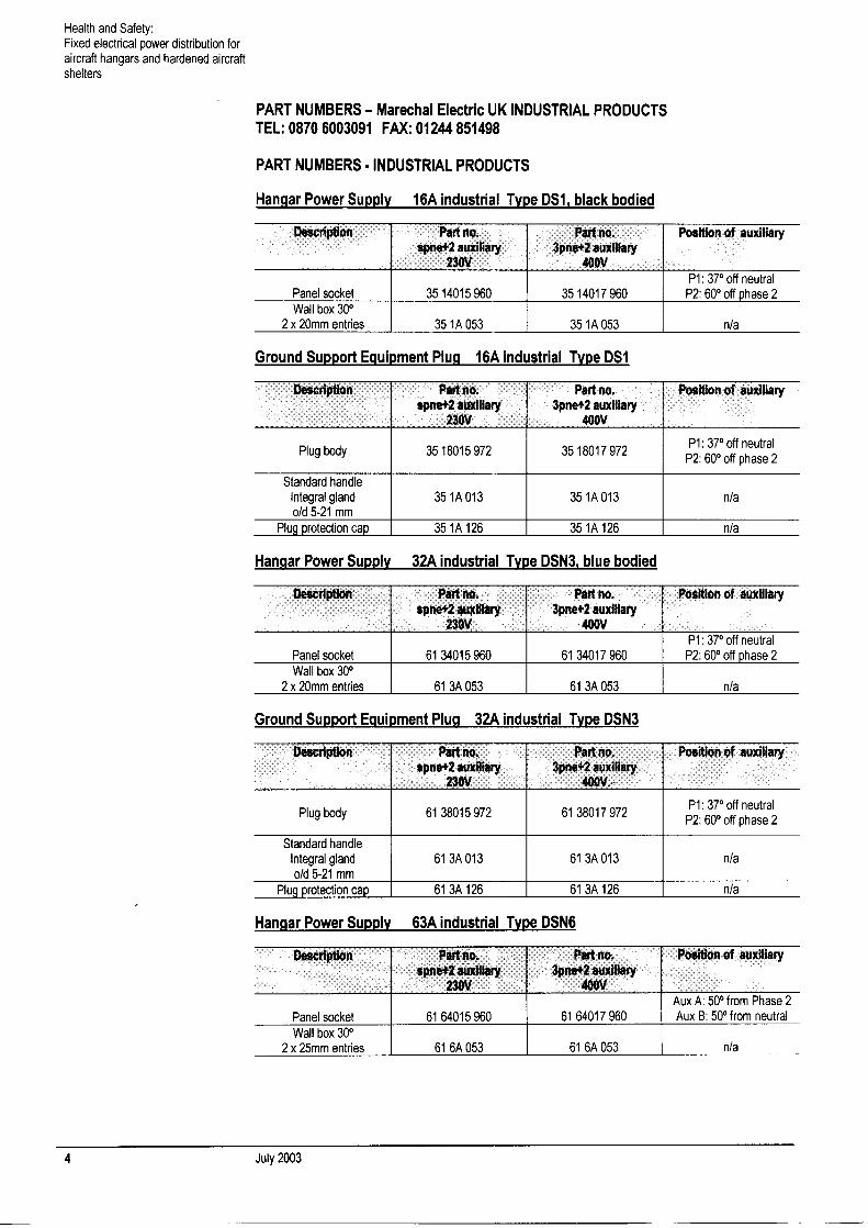
PART NUMBERS — Marechal Electric UK INDUSTRIAL PRODUCTSTEL: 0870 6003091 FAX: 01244851498
PART NUMBERS - INDUSTRIAL PRODUCTS
Hangar Power Supply 16A industrial Type DS1, black bodied
Description Part no.spne+2 auxiliary
230V
Part no.3pne+2 auxiliary
400V
Position of auxiliary
Panel socket 3514015960 3514017960P1: 37°off neutralP2:60°off phase 2
Wall box 30°2 x 20mm entries 35 1A 053 35 1A 053 n/a
Ground Support Equipment Plug 16A industrial Type DSI
Description Part no.spne+2 auxiliary
230V
Part no.3pne+2 auxiliary
400V
Position of auxiliary
Plug body 3518015972 3518017972
Standard handleIntegral glando/d_5-21_mm
35 1A 013 35 1A 013 n/a
Plug protection cap 35 1A 126 35 1A 126 n/a
Hangar Power Supply 32A industrial Type DSN3I blue bodied
Descnptlon Part no.spne+2 auxiliary
230V
Part no.3pne+2 auxiliary
400V
Position of auxiliary
Panel socket 61 34015 960 61 34017 960P1: 37°off neutral
P2: 60°off phase 2Wall box 30°
2 x 20mm entnes 61 3A 053 61 3A 053 n/a
Ground Support Equipment Plug 32A industrial Type DSN3
Description Part no.spne+2 auxiliary
230V
Part no.3pne+2 auxiliary
4OOV~.
Position of auxiliary
Plugbody 6138015972 6138017972
Standard handleIntegral glando/d 5-21 mm
61 3A 013 61 3A 013 n/a
Plug protection cap 61 3A 126 61 3A 126 n/a
Hangar Power Supply 63A industrial Type DSN6
uescnpuon i~anno. rart no. rosiuon of auxiliaryspne+2 auxiliary 3pne+2 auxiliary
230V 400VAux A: 50°from Phase 2
Panel socket 61 64015 960 61 64017 960 Aux B: 50°from neutralWall box 30°
2 x 25mm entries 61 6A 053 61 6A 053 n/a
4 July2003

Health and Safety:Fixed electrical power distribution foraircraft hangars and hardened aircraftshelters
Ground Support Equipment Plug 63A industrial Type DSN6
ry~
Part no.3pne+2 auxiliary
400V
Position of auxiliary
Plug body 61 68015 972 61 68017 972 Aux A: 50°from Phase 2Aux B: 50 from neutral
Standard handleIntegral glando/d_10-30_mm
61 6A 013 61 6A 013 n/a
Plug protection cap 61 6A 126 61 6A 126 n/a
Hangar Power Supply 125A industrial Type DS9
Part no. Part no.spne+2 auxiliary 3pne*2 auxiliary
230V 400V
Ground Support Equipment Plug 125A industrial Type DS9
Description Part no. Part no.spne+2 auxiliary 3pne+2 auxiliary
230V 400V
Position of auxiliary
Plug body 31 98015 172 31 98017 172Single phase
75°from phase 390°from phase 1
Standard handleRequires gland M50 31 9A 253 429 31 9A 253 429
Three phaseP1 &P2: 52.5°off phase
3 phase 2
Plug protection cap 31 9A 126 31 9A 126 n/a
PART NUMBERS - UK HAZARDOUS AREA PRODUCTS
Hangar Power Supply up to 32A hazardous Type DXN3
Description Part no.spne+2 auxiliary
230V
Part no.3pne+2 auxiliary
400V
Position of auxiliary
Panel socket 25 34015 960 25 34017 960P1: 45°off neutral
P2: 45°off phase 2
Wall box 30° 25 3AB53 25 3AB53 n/a
Ground Support Equ~pment Plug up to 32A hazardous Type DXN3
Description Part no. Part no. Position of auxiliaryspne+2 auxiliary 3pne+2 auxiliary
230V 401WP1: 45°off neutral
2538015972 2538017972 P2:45°off phase 2Plug body
Standard handleIntegral Ex gland 25 3A 753 25 3A 753 n/a
Plug protection cap 25 3A 126 25 3A 126 n/a
D
3194015198 3194017198
Position of auxiliary
Single phase75°fromphase390°from_phase_1
Panel socket
Wall box 30° Three phase1 x M50 entry 39 9A 053 39 9A 053 P1&P2: 52.5°
offphase3&phase2
July 2003 5

Health and Safety:Fixed electrical power distribution foraircraft hangars and hardened aircraftshelters
Hanaar Power SuDolv 63A hazardous TvDe DXN6
Description Part no.spne+2 auxiliary
230V
Part no.3pne+2 auxiliary
401W
Position of auxiliary
Panel socket 25 64015 960 25 64017 960Aux A: 45°off neutralAux B: 45°off phase 2
Wall box 30° 25 6AB53 25 6AB53 n/a
Ground Support Equipment Plug 63A hazardous Type DXN6
Description Part no. Part no. Position of auxiliaryspne+2 auxiliary 3pne+2 auxiliary
230V 400VAux A: 45°off neutral
Plug body 2568015972 2568017972 Aux B: 45°off phase 2
Standard handleIntegral Ex gland 25 6A 753 25 6A 753 n/a
Plug protection cap 25 6A 126 25 6A 126 n/a
• Thepilot wire shouldbeconnectedto the auxiliary contactP1 orAux A.
• Socketsandconnectorssupplyingreducedlow voltageandextralowvoltageloadsdo not requirePEMprotectionbut mustcomplywith all otheraspectsof thisTB andCrownFire StandardEl0 for preventionof electricshockandfire.
19. Whereextensionleadsincorporatingplugsandsocketsareusedto extendthesupplyleadto equipment,both theplugsandthe socketsof theextensionleadmustbeeitherlocatedoutsidethe hazardouszones(e.g. on stands)or certifiedfor safeoperationwithin theappropriatehazardouszonefor eachendof theextensionlead.
20. Hardwired extendedsupply leadsor extensionleadsusedto supplynonPEMScompatibleequipmentmustbesupportedin suchaway thatthe leadis outsidethehazardouszone.
Annex C containsdetailsofpilot earthmonitoringsystems.
6 July 2003

Health and Safety:Fixed electrical power distribution foraircraft hangars and hardened aircraftshelters
Annex A - Fixed electrical powerdistribution for aircraft hangars andhardened aircraft shelters
RISK ASSESSMENTThis risk assessmentfor the fixed electricalpowerdistributionin aircraft
hangarsandHASshasbeenmadeon thefollowing basis:
a. The hazards
Thenatureof thework undertakeninside ahangaror HAS will frequentlyrequiretheuseof longmainsand/orextensionleads. In manycases,thesewillbeusedto supplypowerdistributionunitswhich supplyelectricalpower to theaircraftin thehangar/HAS.Thefollowing hazardsareidentified:
• thecableon thehangar/HASfloor is vulnerable. It canberun overby aheavyvehiclewith metalor hardwheelswhich arecapableof damagingallor partof the cable,impairingtheeffectivenessof the safetyearthconductors
• someitemsof equipmenton theaircrafthaveheavydutymainsfilterswhich causehighearthleakagecurrentson the electricitysupplycables.Consequently,thelossof theearthconductorconnectiononthe electricitysupplyfrom thehangar/HASwill leadto dangerousvoltagesappearingonthebodyofthe aircraft, introducingashockhazard. In extremecases(ielossof earthandneutral) this will becapableof causingafatalelectricshock.
• in mostinstances,longmainsleadsareusedin hangars/HASs.On manyoccasions,along extensionleadis usedto supplyotherequipmentwhichaddsto theproblemof alongsupplylead. Oncetheoverall leadlengthexceedsacritical length,themaximumpermitteddisconnectiontimeof 0.4secondsforprotectionagainstelectricshockfor socketoutletscannotbeachievedusingovercurrentprotectionalone.
b. Likelihood of hazard occurring
Thefirst two of thethreehazardsidentifiedabovewill only occurif the cableisdamagedor acableconductorbecomesdisconnected.Eitherof thesescenariosis classifiedas “possible”. The third hazardwill exist on nearlyall occasionsandis, thereforeclassifiedas“probable”.
c. Severity of injury resulting from hazard
In eachcase,theworstcasescenarioproducesthepossibilityof afatalelectricshock.
July2003 7
Health and Safety: Annex AFixed electrical power distribution foraircraft hangars and hardened aircraftshelters
d. Risk assessment without control measures
Thecombinationof likelihoodandseverityproducesa “high risk” categorywhichmeansthatstepsmustbetakento control the risk.
e. Risk control measures
Two measuresof controlwill bringthe overallrisk assessmentdownto an
acceptablelevel:• automaticdisconnectionof electricitysupply in the eventof earthconductor
failure. This is achievedby theuseof apilot earthmonitoringsystem
• reducingthe automaticelectricity supplydisconnectiontime in the eventofanearthfault. This is achievedby theuseof asuitableresidualcurrentdevice.
f. Additional information
Thepilot earthmonitoringsystemfully meetstherequirementsofBS 7671:2001Section607 - “EarthingRequirementsfor theInstallationofEquipmenthavinghighProtectiveConductorCurrents”. It is item(iv) ofRegulation607-02-04,andis the only systemlistedwhichwill givetheadditionalprotectionof automaticallyinterruptingthe supplyif theprotectiveconductorin thecableis broken.
The Institutionof ElectricalEngineersCodeof Practicefor In-serviceInspectionandTestingof Electrical Equipmentgives recommendedmaximumextensionleadlengths. For anextensionleadprotectedby a 13 ampfuse,lengthsare 15 metresfor a 1.5mm2 cableand25 metresfora 2.5 mm2 cable. Iftheleadis longerthanthis, aearthleakageprotectiondevicemustbeusedif themaximumpermitteddisconnectiontimeof 0.4 secondsforprotectionagainstelectricshockis to beachieved.Consequently,thecombinedlengthof anextensionleadanda longequipmentsupply leadmeansthat earthleakageprotectiondeviceis essentialforcompliancewith the shockprotectionregulationsin BS 7671:2001.
g. Risk assessment conclusion
Theoptimumsystemfor safeelectricalpowerdistributionin aircrafthangarsandHASs is acombinationof asuitablyratedearthleakageprotectiondeviceandpemssystem. This reducestherisk from all of theabovehazardsto anacceptablelevel without compromisingoperationalrequirements.
8 July 2003

Health and Safety:Fixed electrical power distribution foraircraft hangars and hardened aircraftshelters
Annex B - RecognisedEU and NorthAmerican Authorities for certificationand testing of electrical equipment inhazardousareas
Table showing country and associated authority.
Country Authority
Belgium INIEX
Canada GSA
Denmark DEMKO
France INERIS
LCIE
Germany PTB
BVS
Italy CESI
Netherlands KEMA
Spain LOM
United Kingdom BASEEFA
SCS
United States of Ame~ca Underwriters Laboratory
Factory Mutual
NOTE:
All EUcertified electricalequipmentfor usein hazardousareaswill bearamarkstartingwith thelettersEx or EExfollowedby aseriesof threecodes,whicharedefinedin BS 5345 Part1: 1989,Codeof Practicefor selection,installationandmaintenanceof electricalapparatusfor usein potentiallyexplosiveatmospheres.Part 1 Generalrecommendations.BS 5345hasbeensupersededby BSEN60079andelectricalequipmentwhichhasto beusedwithin ahazardousareamustcarrythe anappropriateATEX certificateafterJune2005.
July 2003 9

Annex BHealth and Safety:Fixed electrical power distribution foraircraft hangars and hardened aircraftshelters
July2003

Health and Safety:Fixed electrical power distribution foraircraft hangars and hardened aircraftshelters
Annex C - BasicPilot Earth MonitoringSystem
BASIC PILOT EARTH MONITORING SYSTEM
The basicpilot earthmonitoringsystem(PEMS) is illustratedin figure Cl.(Note - theconnectionfrom theearthconductorto themetalworkof themobileor transportableapparatushasbeenomittedin this diagramforclarity). Whenthe switchis closed,andboththe earthconductorandthe pilot conductorareintact, thetransformersuppliescurrentthroughthe earthlead, the diodeat theequipmentendandthepilot leadto the polarisedrelay. Therelayis nowenergisedandswitchesthe line andneutralsuppliesto the load.
2. If theearthconductor(orthepilot conductor)aredamagedandbecomeopencircuit, thentherelaybecomesde-energisedandtheline andneutralsuppliesareautomaticallycut.
3. If thecableis damagedin suchaway thatthepilot andearthconductorareshortcircuitedtogether,thepolarisedrelayreceivesan alternatingcurrentsupply,sincethediodeis no longerin circuit. Thepolarisedrelaywill only operateinthe “energised”modeif it is suppliedwith direct current. Consequently,therelaybehavesas if it werede-energisedandcutsthe supplies.This actionwilltakeplaceregardlessof whetheror not theremoteequipmentis still connectedto the earthconductor.
4. This systemwill provideprotectionagainsttherisk ofelectricshockwhichcouldbecausedby thelossof theelectricalearthconnectionatthe mobileortransportableapparatus.
PRACTICAL PILOT EARTH MONITORING SYSTEMS
5. Whilst thebasissystemwill work, it hasanumberofpracticallimitations.CommercialPEMSovercomemostof thelimitations whicharelikely to beencounteredin theeverydayuseof thesystem. A typical PEMSunit schematicis illustratedatfigure C2.
a. Reverse Diode Facility
If the remoteequipmenthasthediodeconnectedthe wrongway round,therelaywill not energise.Thiscouldleadto expensivedelayswhilst theremoteequipmentis rewired. Furthermore,if the equipmentis onhire, itmaybeabreachof thehire agreementto changethe internalwiring. Thereversediodeswitchsimplyreversesthe connectionsto therelayso thatthePEMSwill becompatiblewith theload.
July 2003 11

Health and Safety: Annex CFixed electrical power distribution foraircraft hangars and hardened aircraftshelters
b. With Diode/Without Diode Switch (may also be labelled “WithRectifier/Without Rectifier”)
Somehire equipmentmaybeprovidedwith the pilot leadandthe earthconductorconnecteddirectly togetherwithout thediodeatthe loadend.
Whilst this doesnot providethesamelevel of protectionasthe systemincorporatingthe diode,it doesprovideprotectionagainstan opencircuitearthconductor.This switchenablesthe systemto operatewith thistypeof load. However,it is importantto ensurethat it is switchedbackto “withdiode” or “with rectifier” afterusein orderto providethe full level ofprotectionfor normalusage.
c. Earth Monitoring Fault Test
This is atest facility which simulatesan earthconductorfault.
d. Earth Leakage Fault Test/Residual Current Device (Circuit Breaker) Test
CommercialPEMSunitswill alsocontainaresidualcurrentdevice(formerlyknownasan EarthLeakageCircuit Breaker)sincethis isincludedin thespecification. Thetestfacility is exactlythe sameasthetestfacility on selfcontainedresidualcurrentdevices.
12 July 2003

Health and Safety:Fixed electrical power distribution foraircraft hangars and hardened aircraftshelters
Annex C
a
I-CU
en
~0C
U
0
UzI
I...soUU)
it
2S
IISI
II
II
I
I
LU
July2003 13

I’H
‘p
IIIJUaSW
C’0
ft1~
aa’iz13
Health and Safety:Fixed electrical power distribution foraircraft hangars and hardened aircraftshelters
Annex C
£1
‘liz ~ z
14 July2003


![Guide to World War II Hangars - 01 - Bellman Hangarwebarchive.nationalarchives.gov.uk/20121026065214/http:/[]/... · Guide to World Chapter 4 – Structural ... Kingdom showing the](https://static.fdocuments.net/doc/165x107/5b1ffe317f8b9ae4208b4a07/guide-to-world-war-ii-hangars-01-bellman-guide-to-world-chapter.jpg)


