He Thong Ke Toan
57
MATLAB Simulation Frequency Diversity: Wide-Band Signals Simulation of Wireless Communication Systems using MATLAB Dr. B.-P. Paris Dept. Electrical and Comp. Engineering George Mason University Fall 2007 Paris ECE 732 1
description
Mo pholng he thong ketoan
Transcript of He Thong Ke Toan

MATLAB SimulationFrequency Diversity: Wide-Band Signals
Simulation of Wireless CommunicationSystems using MATLAB
Dr. B.-P. ParisDept. Electrical and Comp. Engineering
George Mason University
Fall 2007
Paris ECE 732 1

MATLAB SimulationFrequency Diversity: Wide-Band Signals
Discrete-Time Equivalent SystemDigital Matched Filter and SlicerMonte Carlo Simulation
Outline
MATLAB Simulation
Frequency Diversity: Wide-Band Signals
Paris ECE 732 2

MATLAB SimulationFrequency Diversity: Wide-Band Signals
Discrete-Time Equivalent SystemDigital Matched Filter and SlicerMonte Carlo Simulation
MATLAB Simulation
I Objective: Simulate a simple communication system andestimate bit error rate.
I System Characteristics:I BPSK modulation, b ∈ {1,−1} with equal a priori
probabilities,I Raised cosine pulses,I AWGN channel,I oversampled integrate-and-dump receiver front-end,I digital matched filter.
I Measure: Bit-error rate as a function of Es/N0 andoversampling rate.
Paris ECE 732 3

MATLAB SimulationFrequency Diversity: Wide-Band Signals
Discrete-Time Equivalent SystemDigital Matched Filter and SlicerMonte Carlo Simulation
System to be Simulated
× p(t)
∑ δ(t − nT )
×
A
h(t) +
N(t)
ΠTs (t)
Sampler,rate fs
toDSP
bn s(t) R(t) R[n]
Figure: Baseband Equivalent System to be Simulated.
Paris ECE 732 4

MATLAB SimulationFrequency Diversity: Wide-Band Signals
Discrete-Time Equivalent SystemDigital Matched Filter and SlicerMonte Carlo Simulation
From Continuous to Discrete Time
I The system in the preceding diagram cannot be simulatedimmediately.
I Main problem: Most of the signals are continuous-timesignals and cannot be represented in MATLAB.
I Possible Remedies:1. Rely on Sampling Theorem and work with sampled
versions of signals.2. Consider discrete-time equivalent system.
I The second alternative is preferred and will be pursuedbelow.
Paris ECE 732 5
MATLAB SimulationFrequency Diversity: Wide-Band Signals
Discrete-Time Equivalent SystemDigital Matched Filter and SlicerMonte Carlo Simulation
Towards the Discrete-Time Equivalent System
I The shaded portion of the system has a discrete-time inputand a discrete-time output.
I Can be considered as a discrete-time system.I Minor problem: input and output operate at different rates.
× p(t)
∑ δ(t − nT )
×
A
h(t) +
N(t)
ΠTs (t)
Sampler,rate fs
toDSP
bn s(t) R(t) R[n]
Paris ECE 732 6

MATLAB SimulationFrequency Diversity: Wide-Band Signals
Discrete-Time Equivalent SystemDigital Matched Filter and SlicerMonte Carlo Simulation
Discrete-Time Equivalent SystemI The discrete-time equivalent system
I is equivalent to the original system, andI contains only discrete-time signals and components.
I Input signal is up-sampled by factor fsT to make input andoutput rates equal.
I Insert fsT − 1 zeros between input samples.
×
A
↑ fsT h[n] +
N [n]
to DSPbn R[n]
Paris ECE 732 7

MATLAB SimulationFrequency Diversity: Wide-Band Signals
Discrete-Time Equivalent SystemDigital Matched Filter and SlicerMonte Carlo Simulation
Components of Discrete-Time Equivalent System
I Question: What is the relationship between thecomponents of the original and discrete-time equivalentsystem?
× p(t)
∑ δ(t − nT )
×
A
h(t) +
N(t)
ΠTs (t)
Sampler,rate fs
toDSP
bn s(t) R(t) R[n]
Paris ECE 732 8

MATLAB SimulationFrequency Diversity: Wide-Band Signals
Discrete-Time Equivalent SystemDigital Matched Filter and SlicerMonte Carlo Simulation
Discrete-time Equivalent Impulse ResponseI To determine the impulse response h[n] of the
discrete-time equivalent system:I Set noise signal Nt to zero,I set input signal bn to unit impulse signal δ[n],I output signal is impulse response h[n].
I Procedure yields:
h[n] =1Ts
∫ (n+1)Ts
nTs
p(t) ∗ h(t) dt
I For high sampling rates (fsT � 1), the impulse response isclosely approximated by sampling p(t) ∗ h(t):
h[n] ≈ p(t) ∗ h(t)|(n+ 12 )Ts
Paris ECE 732 9

MATLAB SimulationFrequency Diversity: Wide-Band Signals
Discrete-Time Equivalent SystemDigital Matched Filter and SlicerMonte Carlo Simulation
Discrete-time Equivalent Impulse Response
0 0.2 0.4 0.6 0.8 10
0.5
1
1.5
2
Time/T
Figure: Discrete-time Equivalent Impulse Response (fsT = 8)
Paris ECE 732 10

MATLAB SimulationFrequency Diversity: Wide-Band Signals
Discrete-Time Equivalent SystemDigital Matched Filter and SlicerMonte Carlo Simulation
Discrete-Time Equivalent Noise
I To determine the properties of the additive noise N [n] inthe discrete-time equivalent system,
I Set input signal to zero,I let continuous-time noise be complex, white, Gaussian with
power spectral density N0,I output signal is discrete-time equivalent noise.
I Procedure yields: The noise samples N [n]I are independent, complex Gaussian random variables, withI zero mean, andI variance equal to N0/Ts.
Paris ECE 732 11

MATLAB SimulationFrequency Diversity: Wide-Band Signals
Discrete-Time Equivalent SystemDigital Matched Filter and SlicerMonte Carlo Simulation
Received Symbol EnergyI The last entity we will need from the continuous-time
system is the received energy per symbol Es.I Note that Es is controlled by adjusting the gain A at the
transmitter.I To determine Es,
I Set noise N(t) to zero,I Transmit a single symbol bn,I Compute the energy of the received signal R(t).
I Procedure yields:
Es = σ2s · A2
∫|p(t) ∗ h(t)|2 dt
I Here, σ2s denotes the variance of the source. For BPSK,
σ2s = 1.
I For the system under consideration, Es = A2T .
Paris ECE 732 12

MATLAB SimulationFrequency Diversity: Wide-Band Signals
Discrete-Time Equivalent SystemDigital Matched Filter and SlicerMonte Carlo Simulation
Simulating Transmission of Symbols
I We are now in position to simulate the transmission of asequence of symbols.
I The MATLAB functions previously introduced will be usedfor that purpose.
I We proceed in three steps:1. Establish parameters describing the system,
I By parameterizing the simulation, other scenarios are easilyaccommodated.
2. Simulate discrete-time equivalent system,3. Collect statistics from repeated simulation.
Paris ECE 732 13

MATLAB SimulationFrequency Diversity: Wide-Band Signals
Discrete-Time Equivalent SystemDigital Matched Filter and SlicerMonte Carlo Simulation
Listing : SimpleSetParameters.m3 % This script sets a structure named Parameters to be used by
% the system simulator.
%% Parameters% construct structure of parameters to be passed to system simulator
8 % communications parametersParameters.T = 1/10000; % symbol periodParameters.fsT = 8; % samples per symbolParameters.Es = 1; % normalize received symbol energy to 1 (0dB)Parameters.EsOverN0 = 6; % Signal-to-noise ratio (Es/N0)
13 Parameters.Alphabet = [1 -1]; % BPSKParameters.NSymbols = 1000; % number of Symbols
% discrete-time equivalent impulse response (raised cosine pulse)fsT = Parameters.fsT;
18 tts = ( (0:fsT-1) + 1/2 )/fsT;Parameters.hh = sqrt(2/3) * ( 1 - cos(2*pi*tts)*sin(pi/fsT)/(pi/fsT));
Paris ECE 732 14
MATLAB SimulationFrequency Diversity: Wide-Band Signals
Discrete-Time Equivalent SystemDigital Matched Filter and SlicerMonte Carlo Simulation
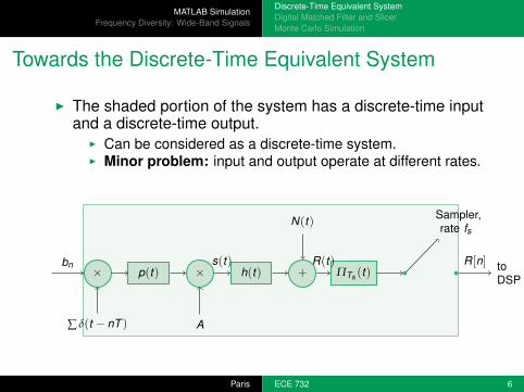
Simulating the Discrete-Time Equivalent System
I The actual system simulation is carried out in MATLABfunction MCSimple which has the function signature below.
I The parameters set in the controlling script are passed asinputs.
I The body of the function simulates the transmission of thesignal and subsequent demodulation.
I The number of incorrect decisions is determined andreturned.
function [NumErrors, ResultsStruct] = MCSimple( ParametersStruct )
Paris ECE 732 15

MATLAB SimulationFrequency Diversity: Wide-Band Signals
Discrete-Time Equivalent SystemDigital Matched Filter and SlicerMonte Carlo Simulation
Simulating the Discrete-Time Equivalent System
I The simulation of the discrete-time equivalent system usestoolbox functions RandomSymbols, LinearModulation, andaddNoise.
A = sqrt(Es/T); % transmitter gainN0 = Es/EsOverN0; % noise PSD (complex noise)NoiseVar = N0/T*fsT; % corresponding noise variance N0/TsScale = A*hh*hh’; % gain through signal chain
34
%% simulate discrete-time equivalent system% transmitter and channel via toolbox functionsSymbols = RandomSymbols( NSymbols, Alphabet, Priors );Signal = A * LinearModulation( Symbols, hh, fsT );
39 if ( isreal(Signal) )Signal = complex(Signal);% ensure Signal is complex-valued
endReceived = addNoise( Signal, NoiseVar );
Paris ECE 732 16

MATLAB SimulationFrequency Diversity: Wide-Band Signals
Discrete-Time Equivalent SystemDigital Matched Filter and SlicerMonte Carlo Simulation
Digital Matched Filter
I The vector Received contains the noisy output samples fromthe analog front-end.
I In a real system, these samples would be processed bydigital hardware to recover the transmitted bits.
I Such digital hardware may be an ASIC, FPGA, or DSP chip.I The first function performed there is digital matched
filtering.I This is a discrete-time implementation of the matched filter
discussed before.I The matched filter is the best possible processor for
enhancing the signal-to-noise ratio of the received signal.
Paris ECE 732 17

MATLAB SimulationFrequency Diversity: Wide-Band Signals
Discrete-Time Equivalent SystemDigital Matched Filter and SlicerMonte Carlo Simulation
Digital Matched Filter
I In our simulator, the vector Received is passed through adiscrete-time matched filter and down-sampled to thesymbol rate.
I The impulse response of the matched filter is the conjugatecomplex of the time-reversed, discrete-time channelresponse h[n].
h∗[−n] ↓ fsT SlicerR[n] bn
Paris ECE 732 18

MATLAB SimulationFrequency Diversity: Wide-Band Signals
Discrete-Time Equivalent SystemDigital Matched Filter and SlicerMonte Carlo Simulation
MATLAB Code for Digital Matched Filter
I The signature line for the MATLAB function implementingthe matched filter is:function MFOut = DMF( Received, Pulse, fsT )
I The body of the function is a direct implementation of thestructure in the block diagram above.
% convolve received signal with conjugate complex of% time-reversed pulse (matched filter)Temp = conv( Received, conj( fliplr(Pulse) ) );
21
% down sample, at the end of each pulse periodMFOut = Temp( length(Pulse) : fsT : end );
Paris ECE 732 19

MATLAB SimulationFrequency Diversity: Wide-Band Signals
Discrete-Time Equivalent SystemDigital Matched Filter and SlicerMonte Carlo Simulation
DMF Input and Output Signal
0 1 2 3 4 5 6 7 8 9 10−400
−200
0
200
400
Time (1/T)
DMF Input
0 1 2 3 4 5 6 7 8 9 10−1000
−500
0
500
1000
1500
Time (1/T)
DMF Output
Paris ECE 732 20

MATLAB SimulationFrequency Diversity: Wide-Band Signals
Discrete-Time Equivalent SystemDigital Matched Filter and SlicerMonte Carlo Simulation
IQ-Scatter Plot of DMF Input and Output
−800 −600 −400 −200 0 200 400 600 800
−200
−100
0
100
200
300
Real Part
Imag
. Par
tDMF Input
−2000 −1500 −1000 −500 0 500 1000 1500 2000
−500
0
500
Real Part
Imag
. Par
t
DMF Output
Paris ECE 732 21

MATLAB SimulationFrequency Diversity: Wide-Band Signals
Discrete-Time Equivalent SystemDigital Matched Filter and SlicerMonte Carlo Simulation
Slicer
I The final operation to be performed by the receiver isdeciding which symbol was transmitted.
I This function is performed by the slicer.I The operation of the slicer is best understood in terms of
the IQ-scatter plot on the previous slide.I The red circles in the plot indicate the noise-free signal
locations for each of the possibly transmitted signals.I For each output from the matched filter, the slicer
determines the nearest noise-free signal location.I The decision is made in favor of the symbol that
corresponds to the noise-free signal nearest the matchedfilter output.
I Some adjustments to the above procedure are neededwhen symbols are not equally likely.
Paris ECE 732 22

MATLAB SimulationFrequency Diversity: Wide-Band Signals
Discrete-Time Equivalent SystemDigital Matched Filter and SlicerMonte Carlo Simulation
MATLAB Function SimpleSlicer
I The procedure above is implemented in a function withsignaturefunction [Decisions, MSE] = SimpleSlicer( MFOut, Alphabet, Scale )
%% Loop over symbols to find symbol closest to MF outputfor kk = 1:length( Alphabet )
% noise-free signal location28 NoisefreeSig = Scale*Alphabet(kk);
% Euclidean distance between each observation and constellation pointDist = abs( MFOut - NoisefreeSig );% find locations for which distance is smaller than previous bestChangedDec = ( Dist < MinDist );
33
% store new min distances and update decisionsMinDist( ChangedDec) = Dist( ChangedDec );Decisions( ChangedDec ) = Alphabet(kk);
end
Paris ECE 732 23

MATLAB SimulationFrequency Diversity: Wide-Band Signals
Discrete-Time Equivalent SystemDigital Matched Filter and SlicerMonte Carlo Simulation
Entire System
I The addition of functions for the digital matched filtercompletes the simulator for the communication system.
I The functionality of the simulator is encapsulated in afunction with signaturefunction [NumErrors, ResultsStruct] = MCSimple( ParametersStruct )
I The function simulates the transmission of a sequence ofsymbols and determines how many symbol errors occurred.
I The operation of the simulator is controlled via theparameters passed in the input structure.
I The body of the function is shown on the next slide; itconsists mainly of calls to functions in our toolbox.
Paris ECE 732 24

MATLAB SimulationFrequency Diversity: Wide-Band Signals
Discrete-Time Equivalent SystemDigital Matched Filter and SlicerMonte Carlo Simulation
Listing : MCSimple.m%% simulate discrete-time equivalent system% transmitter and channel via toolbox functionsSymbols = RandomSymbols( NSymbols, Alphabet, Priors );
38 Signal = A * LinearModulation( Symbols, hh, fsT );if ( isreal(Signal) )
Signal = complex(Signal);% ensure Signal is complex-valuedendReceived = addNoise( Signal, NoiseVar );
43
% digital matched filter and slicerMFOut = DMF( Received, hh, fsT );Decisions = SimpleSlicer( MFOut(1:NSymbols), Alphabet, Scale );
48 %% Count errorsNumErrors = sum( Decisions ~= Symbols );
Paris ECE 732 25

MATLAB SimulationFrequency Diversity: Wide-Band Signals
Discrete-Time Equivalent SystemDigital Matched Filter and SlicerMonte Carlo Simulation
Monte Carlo Simulation
I The system simulator will be the work horse of the MonteCarlo simulation.
I The objective of the Monte Carlo simulation is to estimatethe symbol error rate our system can achieve.
I The idea behind a Monte Carlo simulation is simple:I Simulate the system repeatedly,I for each simulation count the number of transmitted
symbols and symbol errors,I estimate the symbol error rate as the ratio of the total
number of observed errors and the total number oftransmitted bits.
Paris ECE 732 26

MATLAB SimulationFrequency Diversity: Wide-Band Signals
Discrete-Time Equivalent SystemDigital Matched Filter and SlicerMonte Carlo Simulation
Monte Carlo Simulation
I The above suggests a relatively simple structure for aMonte Carlo simulator.
I Inside a programming loop:I perform a system simulation, andI accumulate counts for the quantities of interest
43 while ( ~Done )NumErrors(kk) = NumErrors(kk) + MCSimple( Parameters );NumSymbols(kk) = NumSymbols(kk) + Parameters.NSymbols;
% compute Stop condition48 Done = NumErrors(kk) > MinErrors || NumSymbols(kk) > MaxSymbols;
end
Paris ECE 732 27

MATLAB SimulationFrequency Diversity: Wide-Band Signals
Discrete-Time Equivalent SystemDigital Matched Filter and SlicerMonte Carlo Simulation
Confidence Intervals
I Question: How many times should the loop be executed?I Answer: It depends
I on the desired level of accuracy (confidence), andI (most importantly) on the symbol error rate.
I Confidence Intervals:I Assume we form an estimate of the symbol error rate Pe as
described above.I Then, the true error rate Pe is (hopefully) close to our
estimate.I Put differently, we would like to be reasonably sure that the
absolute difference |Pe − Pe| is small.
Paris ECE 732 28
MATLAB SimulationFrequency Diversity: Wide-Band Signals
Discrete-Time Equivalent SystemDigital Matched Filter and SlicerMonte Carlo Simulation
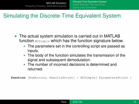
Confidence IntervalsI More specifically, we want a high probability pc (e.g.,
pc =95%) that |Pe − Pe| < sc .I The parameter sc is called the confidence interval;I it depends on the confidence level pc , the error probability
Pe, and the number of transmitted symbols N.I It can be shown, that
sc = zc ·√
Pe(1− Pe)N
,
where zc depends on the confidence level pc .I Specifically: Q(zc) = (1− pc)/2.I Example: for pc =95%, zc = 1.96.
I Question: How is the number of simulations determinedfrom the above considerations?
Paris ECE 732 29

MATLAB SimulationFrequency Diversity: Wide-Band Signals
Discrete-Time Equivalent SystemDigital Matched Filter and SlicerMonte Carlo Simulation
Choosing the Number of Simulations
I For a Monte Carlo simulation, a stop criterion can beformulated from
I a desired confidence level pc (and, thus, zc)I an acceptable confidence interval sc ,I the error rate Pe.
I Solving the equation for the confidence interval for N, weobtain
N = Pe · (1− Pe) · (zc/sc)2.
I A Monte Carlo simulation can be stopped after simulating Ntransmissions.
I Example: For pc =95%, Pe = 10−3, and sc = 10−4, wefind N ≈ 400, 000.
Paris ECE 732 30

MATLAB SimulationFrequency Diversity: Wide-Band Signals
Discrete-Time Equivalent SystemDigital Matched Filter and SlicerMonte Carlo Simulation
A Better Stop-CriterionI When simulating communications systems, the error rate is
often very small.I Then, it is desirable to specify the confidence interval as a
fraction of the error rate.I The confidence interval has the form sc = αc · Pe (e.g.,
αc = 0.1 for a 10% acceptable estimation error).I Inserting into the expression for N and rearranging terms,
Pe ·N = (1− Pe) · (zc/αc)2 ≈ (zc/αc)2.
I Recognize that Pe ·N is the expected number of errors!I Interpretation: Stop when the number of errors reaches
(zc/αc)2.I Rule of thumb: Simulate until 400 errors are found
(pc =95%, α =10%).
Paris ECE 732 31

MATLAB SimulationFrequency Diversity: Wide-Band Signals
Discrete-Time Equivalent SystemDigital Matched Filter and SlicerMonte Carlo Simulation
Listing : MCSimpleDriver.m9 % comms parameters delegated to script SimpleSetParameters
SimpleSetParameters;
% simulation parametersEsOverN0dB = 0:0.5:9; % vary SNR between 0 and 9dB
14 MaxSymbols = 1e6; % simulate at most 1000000 symbols
% desired confidence level an size of confidence intervalConfLevel = 0.95;ZValue = Qinv( ( 1-ConfLevel )/2 );
19 ConfIntSize = 0.1; % confidence interval size is 10% of estimate% For the desired accuracy, we need to find this many errors.MinErrors = ( ZValue/ConfIntSize )^2;
Verbose = true; % control progress output24
%% simulation loops% initialize loop variablesNumErrors = zeros( size( EsOverN0dB ) );NumSymbols = zeros( size( EsOverN0dB ) );
Paris ECE 732 32

MATLAB SimulationFrequency Diversity: Wide-Band Signals
Discrete-Time Equivalent SystemDigital Matched Filter and SlicerMonte Carlo Simulation
Listing : MCSimpleDriver.mfor kk = 1:length( EsOverN0dB )
32 % set Es/N0 for this iterationParameters.EsOverN0 = dB2lin( EsOverN0dB(kk) );% reset stop condition for inner loopDone = false;
37 % progress outputif (Verbose)
disp( sprintf( ’Es/N0: %0.3g dB’, EsOverN0dB(kk) ) );end
42 % inner loop iterates until enough errors have been foundwhile ( ~Done )
NumErrors(kk) = NumErrors(kk) + MCSimple( Parameters );NumSymbols(kk) = NumSymbols(kk) + Parameters.NSymbols;
47 % compute Stop conditionDone = NumErrors(kk) > MinErrors || NumSymbols(kk) > MaxSymbols;
end
Paris ECE 732 33

MATLAB SimulationFrequency Diversity: Wide-Band Signals
Discrete-Time Equivalent SystemDigital Matched Filter and SlicerMonte Carlo Simulation
Simulation Results
−2 0 2 4 6 8 1010
−5
10−4
10−3
10−2
10−1
Es/N
0 (dB)
Sym
bol E
rror
Rat
e
Paris ECE 732 34

MATLAB SimulationFrequency Diversity: Wide-Band Signals
Discrete-Time Equivalent SystemDigital Matched Filter and SlicerMonte Carlo Simulation
Summary
I Introduced discrete-time equivalent systems suitable forsimulation in MATLAB.
I Relationship between original, continuous-time system anddiscrete-time equivalent was established.
I Digital post-processing: digital matched filter and slicer.I Monte Carlo simulation of a simple communication system
was performed.I Close attention was paid to the accuracy of simulation
results via confidence levels and intervals.I Derived simple rule of thumb for stop-criterion.
Paris ECE 732 35
MATLAB SimulationFrequency Diversity: Wide-Band Signals
Discrete-Time Equivalent SystemDigital Matched Filter and SlicerMonte Carlo Simulation
Where we are ...
I Laid out a structure for describing and analyzingcommunication systems in general and wireless systemsin particular.
I Saw a lot of MATLAB examples for modeling diverseaspects of such systems.
I Conducted a simulation to estimate the error rate of acommunication system and compared to theoreticalresults.
I To do: consider selected aspects of wirelesscommunication systems in more detail, including:
I modulation and bandwidth,I wireless channels,I advanced techniques for wireless communications.
Paris ECE 732 36

MATLAB SimulationFrequency Diversity: Wide-Band Signals
Introduction to EqualizationMATLAB SimulationMore Ways to Create Diversity
Outline
MATLAB Simulation
Frequency Diversity: Wide-Band Signals
Paris ECE 732 37

MATLAB SimulationFrequency Diversity: Wide-Band Signals
Introduction to EqualizationMATLAB SimulationMore Ways to Create Diversity
Frequency Diversity through Wide-Band Signals
I We have seen above that narrow-band systems do nothave built-in diversity.
I Narrow-band signals are susceptible to have the entiresignal affected by a deep fade.
I In contrast, wide-band signals cover a bandwidth that iswider than the coherence bandwidth.
I Benefit: Only portions of the transmitted signal will beaffected by deep fades (frequency-selective fading).
I Disadvantage: Short symbol duration induces ISI; receiveris more complex.
I The benefits, far outweigh the disadvantages andwide-band signaling is used in most modern wirelesssystems.
Paris ECE 732 38

MATLAB SimulationFrequency Diversity: Wide-Band Signals
Introduction to EqualizationMATLAB SimulationMore Ways to Create Diversity
Illustration: Built-in Diversity of Wide-band Signals
I We illustrate that wide-band signals do provide diversity bymeans of a simple thought experiments.
I Thought experiment:I Recall that in discrete time a multi-path channel can be
modeled by an FIR filter.I Assume filter operates at symbol rate Ts.I The delay spread determines the number of taps L.
I Our hypothetical system transmits one information symbolin every L-th symbol period and is silent in between.
I At the receiver, each transmission will produce L non-zeroobservations.
I This is due to multi-path.I Observation from consecutive symbols don’t overlap (no ISI)
I Thus, for each symbol we have L independentobservations, i.e., we have L-fold diversity.
Paris ECE 732 39

MATLAB SimulationFrequency Diversity: Wide-Band Signals
Introduction to EqualizationMATLAB SimulationMore Ways to Create Diversity
Illustration: Built-in Diversity of Wide-band Signals
I We will demonstrate shortly that it is not necessary toleave gaps in the transmissions.
I The point was merely to eliminate ISI.I Two insights from the thought experiment:
I Wide-band signals provide built-in diversity.I The receiver gets to look at multiple versions of the
transmitted signal.I The order of diversity depends on the ratio of delay spread
and symbol duration.I Equivalently, on the ratio of signal bandwidth and coherence
bandwidth.I We are looking for receivers that both exploit the built-in
diversity and remove ISI.I Such receiver elements are called equalizers.
Paris ECE 732 40

MATLAB SimulationFrequency Diversity: Wide-Band Signals
Introduction to EqualizationMATLAB SimulationMore Ways to Create Diversity
Equalization
I Equalization is obviously a very important and wellresearched problem.
I Equalizers can be broadly classified into three categories:1. Linear Equalizers: use an inverse filter to compensate for
the variations in the frequency response.I Simple, but not very effective with deep fades.
2. Decision Feedback Equalizers: attempt to reconstruct ISIfrom past symbol decisions.
I Simple, but have potential for error propagation.3. ML Sequence Estimation: find the most likely sequence
of symbols given the received signal.I Most powerful and robust, but computationally complex.
Paris ECE 732 41

MATLAB SimulationFrequency Diversity: Wide-Band Signals
Introduction to EqualizationMATLAB SimulationMore Ways to Create Diversity
Maximum Likelihood Sequence Estimation
I Maximum Likelihood Sequence Estimation provides themost powerful equalizers.
I Unfortunately, the computational complexity growsexponentially with the ratio of delay spread and symbolduration.
I I.e., with the number of taps in the discrete-time equivalentFIR channel.
Paris ECE 732 42

MATLAB SimulationFrequency Diversity: Wide-Band Signals
Introduction to EqualizationMATLAB SimulationMore Ways to Create Diversity
Maximum Likelihood Sequence Estimation
I The principle behind MLSE is simple.I Given a received sequence of samples R[n], e.g., matched
filter outputs, andI a model for the output of the multi-path channel:
r [n] = s[n] ∗ h[n], whereI s[n] denotes the symbol sequence, andI h[n] denotes the discrete-time channel impulse response,
i.e., the channel taps.I Find the sequence of information symbol s[n] that
minimizes
D2 =N
∑n|r [n]− s[n] ∗ h[n]|2.
Paris ECE 732 43

MATLAB SimulationFrequency Diversity: Wide-Band Signals
Introduction to EqualizationMATLAB SimulationMore Ways to Create Diversity
Maximum Likelihood Sequence Estimation
I The criterion
D2 =N
∑n|r [n]− s[n] ∗ h[n]|2.
I performs diversity combining (via s[n] ∗ h[n]), andI removes ISI.
I The minimization of the above metric is difficult because itis a discrete optimization problem.
I The symbols s[n] are from a discrete alphabet.I A computationally efficient algorithm exists to solve the
minimization problem:I The Viterbi Algorithm.I The toolbox contains an implementation of the Viterbi
Algorithm in function va.
Paris ECE 732 44

MATLAB SimulationFrequency Diversity: Wide-Band Signals
Introduction to EqualizationMATLAB SimulationMore Ways to Create Diversity
MATLAB Simulation
I A Monte Carlo simulation of a wide-band signal with anequalizer is conducted
I to illustrate that diversity gains are possible, andI to measure the symbol error rate.
I As before, the Monte Carlo simulation is broken intoI set simulation parameter (script VASetParameters),I simulation control (script MCVADriver), andI system simulation (function MCVA).
Paris ECE 732 45

MATLAB SimulationFrequency Diversity: Wide-Band Signals
Introduction to EqualizationMATLAB SimulationMore Ways to Create Diversity
MATLAB Simulation: System Parameters
Listing : VASetParameters.mParameters.T = 1/1e6; % symbol periodParameters.fsT = 8; % samples per symbolParameters.Es = 1; % normalize received symbol energy to 1 (0dB)Parameters.EsOverN0 = 6; % Signal-to-noise ratio (Es/N0)
13 Parameters.Alphabet = [1 -1]; % BPSKParameters.NSymbols = 500; % number of Symbols per frame
Parameters.TrainLoc = floor(Parameters.NSymbols/2); % location of training seqParameters.TrainLength = 40;
18 Parameters.TrainingSeq = RandomSymbols( Parameters.TrainLength, ...Parameters.Alphabet, [0.5 0.5] );
% channelParameters.ChannelParams = tux(); % channel model
23 Parameters.fd = 3; % DopplerParameters.L = 6; % channel order
Paris ECE 732 46

MATLAB SimulationFrequency Diversity: Wide-Band Signals
Introduction to EqualizationMATLAB SimulationMore Ways to Create Diversity
MATLAB Simulation
I The first step in the system simulation is the simulation ofthe transmitter functionality.
I This is identical to the narrow-band case, except that thebaud rate is 1 MHz and 500 symbols are transmitted perframe.
I There are 40 training symbols.
Listing : MCVA.m41 % transmitter and channel via toolbox functions
InfoSymbols = RandomSymbols( NSymbols, Alphabet, Priors );% insert training sequenceSymbols = [ InfoSymbols(1:TrainLoc) TrainingSeq ...
InfoSymbols(TrainLoc+1:end)];46 % linear modulation
Signal = A * LinearModulation( Symbols, hh, fsT );
Paris ECE 732 47

MATLAB SimulationFrequency Diversity: Wide-Band Signals
Introduction to EqualizationMATLAB SimulationMore Ways to Create Diversity
MATLAB Simulation
I The channel is simulated without spatial diversity.I To focus on the frequency diversity gained by wide-band
signaling.I The channel simulation invokes the time-varying multi-path
simulator and the AWGN function.
% time-varying multi-path channels and additive noiseReceived = SimulateCOSTChannel( Signal, ChannelParams, fs);
51 Received = addNoise( Received, NoiseVar );
Paris ECE 732 48

MATLAB SimulationFrequency Diversity: Wide-Band Signals
Introduction to EqualizationMATLAB SimulationMore Ways to Create Diversity
MATLAB Simulation
I The receiver proceeds as follows:I Digital matched filtering with the pulse shape; followed by
down-sampling to 2 samples per symbol.I Estimation of the coefficients of the FIR channel model.I Equalization with the Viterbi algorithm; followed by removal
of the training sequence.
MFOut = DMF( Received, hh, fsT/2 );
% channel estimation57 MFOutTraining = MFOut( 2*TrainLoc+1 : 2*(TrainLoc+TrainLength) );
ChannelEst = EstChannel( MFOutTraining, TrainingSeq, L, 2);
% VA over MFOut using ChannelEstDecisions = va( MFOut, ChannelEst, Alphabet, 2);
62 % strip training sequence and possible extra symbolsDecisions( TrainLoc+1 : TrainLoc+TrainLength ) = [ ];
Paris ECE 732 49

MATLAB SimulationFrequency Diversity: Wide-Band Signals
Introduction to EqualizationMATLAB SimulationMore Ways to Create Diversity
Channel Estimation
I Channel Estimate:
h = (S′S)−1 · S′r,
whereI S is a Toeplitz matrix constructed from the training
sequence, andI r is the corresponding received signal.
TrainingSPS = zeros(1, length(Received) );14 TrainingSPS(1:SpS:end) = Training;
% make into a Toepliz matrix, such that T*h is convolutionTrainMatrix = toeplitz( TrainingSPS, [Training(1) zeros(1, Order-1)]);
19 ChannelEst = Received * conj( TrainMatrix) * ...inv(TrainMatrix’ * TrainMatrix);
Paris ECE 732 50

MATLAB SimulationFrequency Diversity: Wide-Band Signals
Introduction to EqualizationMATLAB SimulationMore Ways to Create Diversity
Simulated Symbol Error Rate with MLSE Equalizer
0 2 4 6 8 10 1210
−8
10−7
10−6
10−5
10−4
10−3
10−2
10−1
Es/N
0 (dB)
Sym
bol E
rror
Rat
e
Simulated VAL=1L=2L=3L=4L=5AWGN
Figure: Symbol Error Rate with Viterbi Equalizer over Multi-pathFading Channel; Rayleigh channels with transmitter diversity shownfor comparison. Baud rate 1MHz, Delay spread ≈ 2µs.
Paris ECE 732 51

MATLAB SimulationFrequency Diversity: Wide-Band Signals
Introduction to EqualizationMATLAB SimulationMore Ways to Create Diversity
ConclusionsI The simulation indicates that the wide-band system with
equalizer achieves a diversity gain similar to a system withtransmitter diversity of order 2.
I The ratio of delay spread to symbol rate is 2.I comparison to systems with transmitter diversity is
appropriate as the total average power in the channel tapsis normalized to 1.
I Performance at very low SNR suffers, probably, frominaccurate estimates.
I Higher gains can be achieved by increasing bandwidth.I This incurs more complexity in the equalizer, andI potential problems due to a larger number of channel
coefficients to be estimated.I Alternatively, this technique can be combined with
additional diversity techniques (e.g., spatial diversity).
Paris ECE 732 52

MATLAB SimulationFrequency Diversity: Wide-Band Signals
Introduction to EqualizationMATLAB SimulationMore Ways to Create Diversity
More Ways to Create Diversity
I A quick look at three additional ways to create and exploitdiversity.
1. Time diversity.2. Frequency Diversity through OFDM.3. Multi-antenna systems (MIMO)
Paris ECE 732 53

MATLAB SimulationFrequency Diversity: Wide-Band Signals
Introduction to EqualizationMATLAB SimulationMore Ways to Create Diversity
Time DiversityI Time diversity: is created by sending information multiple
times in different frames.I This is often done through coding and interleaving.I This technique relies on the channel to change sufficiently
between transmissions.I The channel’s coherence time should be much smaller than
the time between transmissions.I If this condition cannot be met (e.g., for slow-moving
mobiles), frequency hopping can be used to ensure that thechannel changes sufficiently.
I The diversity gain is (at most) equal to the number oftime-slots used for repeating information.
I Time diversity can be easily combined with frequencydiversity as discussed above.
I The combined diversity gain is the product of the individualdiversity gains.
Paris ECE 732 54

MATLAB SimulationFrequency Diversity: Wide-Band Signals
Introduction to EqualizationMATLAB SimulationMore Ways to Create Diversity
OFDM
I OFDM has received a lot of interest recently.I OFDM can elegantly combine the benefits of narrow-band
signals and wide-band signals.I Like for narrow-band signaling, an equalizer is not required;
merely the gain for each subcarier is needed.I Very low-complexity receivers.
I OFDM signals are inherently wide-band; frequencydiversity is easily achieved by repeating information (reallycoding and interleaving) on widely separated subcarriers.
I Bandwidth is not limited by complexity of equalizer;I High signal bandwidth to coherence bandwidth is possible;
high diversity.
Paris ECE 732 55

MATLAB SimulationFrequency Diversity: Wide-Band Signals
Introduction to EqualizationMATLAB SimulationMore Ways to Create Diversity
MIMOI We have already seen that multiple antennas at the
receiver can provide both diversity and array gain.I The diversity gain ensures that the likelihood that there is
no good channel from transmitter to receiver is small.I The array gain exploits the benefits from observing the
transmitted energy multiple times.I If the system is equipped with multiple transmitter
antennas, then the number of channels equals the productof the number of antennas.
I Very high diversity.I Recently, it has been found that multiple streams can be
transmitted in parallel to achieve high data rates.I Multiplexing gain
I The combination of multi-antenna techniques and OFDMappears particularly promising.
Paris ECE 732 56

MATLAB SimulationFrequency Diversity: Wide-Band Signals
Introduction to EqualizationMATLAB SimulationMore Ways to Create Diversity
Summary
I A close look at the detrimental effect of typical wirelesschannels.
I Narrow-band signals without diversity suffer poorperformance (Rayleigh fading).
I Simulated narrow-band system.I To remedy this problem, diversity is required.
I Analyzed systems with antenna diversity at the receiver.I Verified analysis through simulation.
I Frequency diversity and equalization.I Introduced MLSE and the Viterbi algorithm for equalizing
wide-band signals in multi-path channels.I Simulated system and verified diversity.
I A brief look at other diversity techniques.
Paris ECE 732 57