HDMI Matrix. 8x8 built-in WiFi LM-MX88HDMI Matrix. 8x8 built-in WiFi LM-MX88 Dear Customer Thank you...
18
HDMI Matrix . 8x8 built-in WiFi LM-MX88 Dear Customer Thank you for purchasing this product. For optimum performance and safety, please read these instructions carefully before connecting, operating or adjusting this product. Please keep this manual for future reference.
Transcript of HDMI Matrix. 8x8 built-in WiFi LM-MX88HDMI Matrix. 8x8 built-in WiFi LM-MX88 Dear Customer Thank you...

HDMI Matrix. 8x8 built-in WiFi
LM-MX88
Dear Customer
Thank you for purchasing this product. For optimum performance and safety,
please read these instructions carefully before connecting, operating or
adjusting this product. Please keep this manual for future reference.

Features
Any eight sources to any eight displays, each port supports HDMI or DVI
inputs
The HDMI input is compensated, clock/phase adjusted and jitter free so
all the user sees is a high quality HDMI signal.
Independent switch able EDID function for choosing which resolution to
display.
Support High definition resolutions 1080p, 1080i, 720p and other
standard video formats.
Supports LPCM 7.1 channel output from each of the independent HDMI
ports
Switching modes: panel buttons, local IR, RS232 and Smart phone.
HDCP Compliant
1U’srack design for easy installation
Supports 3D
With wifi.
Notice
Our company reserve the right to make changes in the hardware, packaging
and any accompanying documentation without prior written notice.


2
Table of contents
Package Contents
Dimensional
drawing
Specifications
Panel Descriptions
Connecting and Operating
Typical Application
Maintenance
Product Service
Warranty
Packing contents
1) Main Unit: 8x8 HDMI Matrix
2) Power supply DC 12V 3A
3) Remote Controller
4) IR-RX cable x 1PCS
5) M3x5 Screw x 6PCS
6) Operating Instructions
7) Mounting ear
8) RS232 cable
Dimensional drawing

3
465mm
44
.5
436.9mm
211
mm

4
-5 to +35 C(+23 to +95 F)
5 to 90%RH (No Condensation)
225MHz/6.75Gbps
Up to 1080p@60Hz@36 b/pixels, support 3D
HDMI receptacle. Power
connector terminal Power
DC receptacle
IR Extender
1080P 15m over HDMI cable
110-240V/ 12VDC power supply
24Watts
Cold-Rolled (Cold Rolled) Steel
W436.9xH211xT44.5mm
2800g
5
Front Panel
6 7
1 This monitor displays your settings information with each output and input selection 2 IR windows:: infrared sensor to receive any IR commands from the IR remote control.
3 OUT 1~8 & IN 1~8: Press the output source selection button in order to choose which
input port corresponds to the desired output port. First select your output port from 1-8,
wait 1 sec, then choose the desired input port from ports 1-8. Each output selection only
allows a single input setting each time.

5
4 ALL: Press this button to set all the outputs to display with the same input. frist pressing
the “All”button then press an input number to confirm the selection.
5 LOCK: Press this button to lock all the functions and press it again to release the lock. 6 WIFI: This slot is used to install the antenna.
7 Assembly ear
1 2 Rear Panel 5
3 4 6 7
1 RS232 port :For HDMI matrix control use pc.
2 RS232 port :For WIFI module setup.
3 HDMI input port(HDMI or DVI) .
4 HDMI Output port . 5 POWER: Press this button to turn the system on. 6 IR extender : This slot is where you can extend your IR receiver with an IR extender
cable that supports only 38KHz.
7 Power input : Plug the 12V DC power supply into the unit and connect the adaptor to
an AC wall outlet.
Connecting and operating
1) Connect the HDMI input sources into 8x8 HDMI Matrix and note the input chosen.
2) Connect HDMI OUT of 8x8 HDMI Matrix to display equipment.
3) Connect IR-RX cable into IR-RX Ext port on the receiver and affix the IR receiver in direct line
of site with the handheld remote control. It is recommended to affix the receiver on the display
frame /bezel or the display stand.
Note: Do not affix the emitter until the placement is tested. 4) Power up all units, the matrix, Receiver, sources and displays. 5) Use remote or select the button on the front panel to choose the desired input source.

6
Operation
1-1 2-2 3-3 4-4
5-5 6-6 7-7 8-8
1. Front panel control
The HDMI matrix front panel control switching inputs to the various outputs. There are
four groups of LEDs for each output port. The LED lit on the position means that the output
port selects this input as its source.
2. Local IR remote control
User can control the HDMI route of the matrix by using the
IR remote. There are two group key pads for sixteen ports.
Press the output source selection button in order to choose
which input port corresponds to the desired output port. (For
example: Output 8 select Input7 source, first Press out
8,then press in 7,LCD display 8-7)
3. IR extender control
User can use the IR receiver cable to change the IR receiver
position. If controlling the HDMI matrix through the 1/8” (3.5
mm) input jack on the rear panel, connect the IR cable directly
to the matrix rear IR Ext socket.
4. RS232 remote control. 1. The Message Window
7
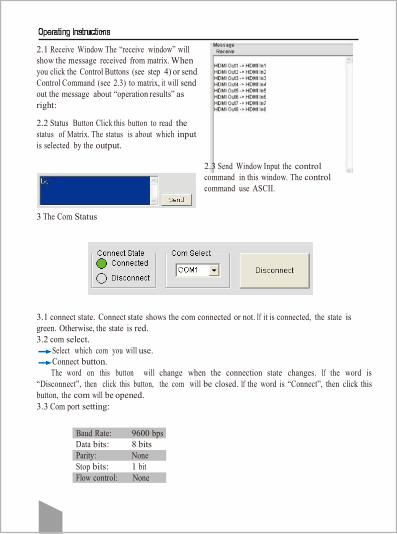
2.1 Receive Window The “receive window” will
show the message received from matrix. When
you click the Control Buttons (see step 4) or send
Control Command (see 2.3) to matrix, it will send
out the message about “operation results” as
right:
2.2 Status Button Click this button to read the
status of Matrix. The status is about which input
is selected by the output.
2.3 Send Window Input the control
command in this window. The control
command use ASCII.
3 The Com Status
3.1 connect state. Connect state shows the com connected or not. If it is connected, the state is
green. Otherwise, the state is red.
3.2 com select.
Select which com you will use.
Connect button.
The word on this button will change when the connection state changes. If the word is
“Disconnect”, then click this button, the com will be closed. If the word is “Connect”, then click this
button, the com will be opened.
3.3 Com port setting:
Baud Rate: 9600 bps
Data bits: 8 bits
Parity: None
Stop bits: 1 bit
Flow control: None

4 Setting Button Click this
button to enter Setting
menu. If the signal is not
stable, please turn on the
HDMI long cable mode.
4.1 EDID Set button Select the Output Port in “Port Select” column, click “Read EDID” button to
get EDID from display equipment. Select the Input Port in “Port Select” column, click “Download”
button to set EDID of this Input Port the same as display equipment. Click “Save as” button to
save EDID read from display equipment as “*.bin” file. Click “Open EDID” button to open saved
“*.bin” file, select the Input Port in “Port Select” column, click “Download” button to set EDID of
this Input Port the same as “*.bin” file.
7
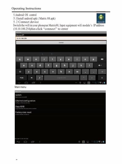
Operating Instructions
5.Android OS control 5.1Install android apk ( Matrix 88.apk) 5. 2 Connect device Switch the wifi in your phone, run Matrix88, Input equipment wifi module’s IP address
(10.10.100.254), then click “connect” to enter
Main menu
.

6.IOS control 5.1 install IOS app ( Matrix 8*8.ipa)
5.2 control device Switch the wifi in your iphone/ipad, run matrix88 Input equipment WIFI module’s IP address (10.10.100.254), then click "Button" to enter
Main næ nu


10
RS-232 pin assignment
HDMI Matrix PIN Remote Control Console
1 Assignment PIN Assignment
2 NC 1 NC
3 TX 2 RX
4 RX 3 TX
5 NC 4 NC
6 GND 5 GND
7 NC 6 NC
8 NC 7 NC
9 NC 8 NC
NC 9 NC

DVD PC HD camera IPTV
Blue-ray player PS3 Xbox STB
HDMI matrix
TV1 TV2 TV3 TV4
TV5 TV6 TV7 TV8
HDMI cable
11

12
RS-232 Commands
command HEX feedback description
cir_0x\r\n 63 69 72 20 30 xx 0D 0A s1y Output 1 select input 1~8 “x” : indicate the
input port, range from 0~7. “y” : indicate the
input port, range from 1~8.
cir_1x\r\n 63 69 72 20 31 xx 0D 0A s2y Output 2 select input 1~8 “x” : indicate the
input port, range from 0~7. “y” : indicate the
input port, range from 1~8.
cir_2x\r\n 63 69 72 20 32 xx 0D 0A s3y Output 3 select input 1~8 “x” : indicate the
input port, range from 0~7. “y” : indicate the
input port, range from 1~8.
cir_3x\r\n 63 69 72 20 33 xx 0D 0A s4y Output 4 select input 1~8 “x” : indicate the
input port, range from 0~7. “y” : indicate the
input port, range from 1~8.
cir_4x\r\n 63 69 72 20 34 xx 0D 0A s5y Output 5 select input 1~8 “x” : indicate the
input port, range from 0~7. “y” : indicate the
input port, range from 1~8.
cir_5x\r\n 63 69 72 20 35 xx 0D 0A s6y Output 6 select input 1~8 “x” : indicate the
input port, range from 0~7. “y” : indicate the
input port, range from 1~8.
cir_6x\r\n 63 69 72 20 36 xx 0D 0A s7y Output 7 select input 1~8 “x” : indicate the
input port, range from 0~7. “y” : indicate the
input port, range from 1~8.
cir_7x\r\n 63 69 72 20 37 xx 0D 0A s8y Output 8 select input 1~8 “x” : indicate the
input port, range from 0~7. “y” : indicate the
input port, range from 1~8.
asw_x\r\n 61 73 77 20 xx 0D 0A s1y s2y
s3y s4y
s5y s6y
s7y s8y
All output select input x; “x” : indicate the
input port, range from 0~7. “y” : indicate the
input port, range from 1~8.
asw_x\r\n 61 73 77 20 xx 0D 0A s1x s2x
s3x s4x
s5x s6x
s7x s8x
Obtain the input status. “x” : indicate the
input port, range from 1~8.
sed_x_y\r\n 73 65 64 20 xx yy 0D 0A sed_x_y Copy edid from “x” to “y”,
“x””y” range from 0~7
rst_\r\n 72 73 74 20 0D 0A Reset factory settings

Operating Instructions
Maintenance Clean this unit with a soft, dry cloth. Never use alcohol, paint thinner of benzene to clean this unit.
Product Service
Damage requiring service: The unit should be serviced by qualified service personnel if: a) The DC power supply cord or AC adaptor has been damaged; b) Objects or liquids have gotten into the unit; c) The unit has been exposed to rain; d) The unit does not operate normally or exhibits a marked change in
performance; e) The unit has been dropped or the cabinet damaged Servicing Personnel: Do not attempt to service the unit beyond that described in these operating instructions. Refer all other servicing to authorized servicing personnel. Replacement Parts: When parts need replacing ensure the servicer uses parts specified by the manufacturer or parts that have the same characteristics as the original parts. Unauthorized substitutes may result in fire, electric shock, or other hazards. Safety Check: After repairs or service, ask the servicer to perform safety checks to confirm that the unit is in proper working condition. Warranty If your product does not work properly because of a defect in material or workmanship, our company ( referred to as “ the warrantor”) will, for the length of the period indicated as below, ( parts (1) year, Labor (90) days ) which starts with the date of original purchase ( “ Limited Warranty period “ ) at its option either (a) repair your product with new or refurbished parts, or (b) replace it with a new of a refurbished product. The decision to repair or replace will be made by the warrantor. During the “Labor” Limited Warranty period, there will be no charge for labor. During the “ Parts” warranty period, there will be no charge for parts. You must mail-in your product during the warranty period. This limited warranty is extended only to the original purchaser and only covers product purchased as new. A purchase receipt or other proof of original purchase date is required for limited warranty service. Mail-in Service

When Shipping the unit carefully pack and send it prepaid, adequately insured and preferably in the original carton. Include a letter detailing the complaint and provide a day time phone and/or e-mail address where you can be reached. Limited warranty limits and exclusions
1) This limited warranty only covers failures due to defects in material or workmanship, and does not cover normal wear and tear or cosmetic damage. The Limited Warranty also does not cover damages which occurred in shipment, or failures which are caused by products not supplied by warrantor, or failures which result from accidents, misuse, abuse, neglect, mishandling, misapplication, alteration, faulty installation, set-up adjustments, misadjustment of consumer controls, improper maintenance, power line surge, lightning damage, modification, or service by anyone other than a factory service center or other Authorized Servicer, or damage that is attributable to cats of God.
2) There are no express warranties except as listed under ”Limited warranty coverage”. The warrantor is not liable for incidental or consequential damages resulting from the use of this product, or arising out of any breach of this warranty. ( As examples, this excludes damages for lost time, cost of having someone remove or re-install an installed unit if applicable, travel to and from the service, loss of or damage to media or images, data or other recorded content. The items listed are not exclusive, but are for illustration only).
3) Parts and service, which are not covered by this limited warranty, are your responsibility.