HDMI 4x8 Matrix Switch, HDBT PoE - MuxLab...
62
HDMI 4x8 & 8x8 Matrix Switch, HDBT, PoE 500418-POE-(US, UK, Euro) 500419-POE-(US, UK, Euro) 500468-POE-(US, UK, Euro) 500469-POE-(US, UK, Euro) Installation Guide P/N: 94-000757-B SE-000757-B
-
Upload
duongthien -
Category
Documents
-
view
237 -
download
5
Transcript of HDMI 4x8 Matrix Switch, HDBT PoE - MuxLab...
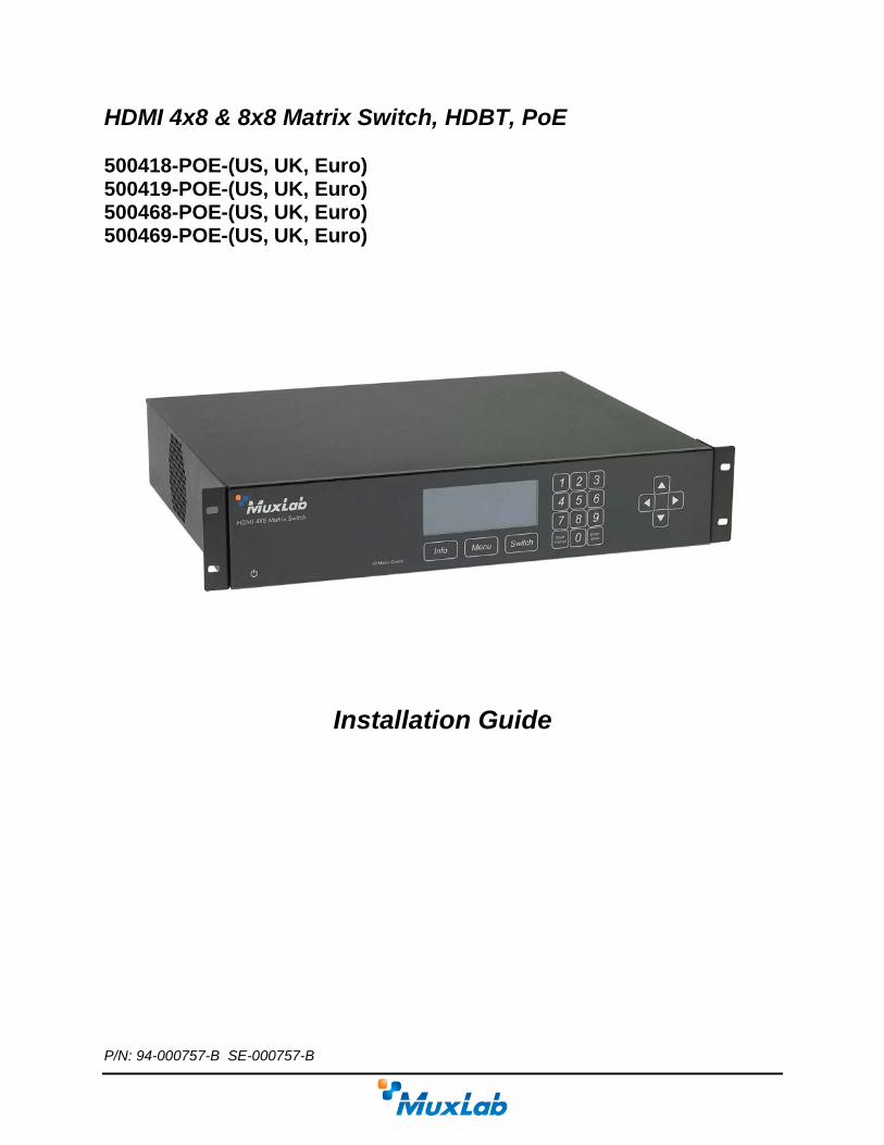
HDMI 4x8 & 8x8 Matrix Switch, HDBT, PoE 500418-POE-(US, UK, Euro) 500419-POE-(US, UK, Euro) 500468-POE-(US, UK, Euro) 500469-POE-(US, UK, Euro)
Installation Guide
P/N: 94-000757-B SE-000757-B
© MuxLab Inc. HDMI 4x8 & 8x8 Matrix Switch, HDBT, PoE Installation Guide
Copyright Notice: Copyright © 2014 MuxLab Inc. All rights reserved. Copyright © 2009 Real Time Engineers Ltd. This product uses an unmodified version of FreeRTOS V6.0.0. Source code available at www.freertos.com Printed in Canada. No part of this publication may be reproduced, stored in a retrieval system, or transmitted in any form or by any means, electronic, mechanical, photocopying, recording or otherwise without prior written permission of the author.
Trademarks: MuxLab is a registered trademark of MuxLab Inc.
Page 2
© MuxLab Inc. HDMI 4x8 & 8x8 Matrix Switch, HDBT, PoE Installation Guide
Table of Contents
1. Overview .....................................................................................................................................4 1.1. Description ............................................................................................................................... 4 1.2. Features .................................................................................................................................... 5
2. Technical Specifications ............................................................................................................6
3. Installation Procedure ...............................................................................................................7 3.1. Part List .................................................................................................................................... 7 3.2. Product Overview .................................................................................................................... 8 3.3. Pre-Installation Checklist ....................................................................................................... 10 3.4. Physical Installation ............................................................................................................... 11 3.5. Installation Procedure ............................................................................................................ 12 3.6. Manual Control ...................................................................................................................... 15 3.7. Remote Control of Matrix Switch .......................................................................................... 24 3.8. Remote Control of Sources and Displays .............................................................................. 25 3.9. EDID and DIP Switch Settings .............................................................................................. 26 3.10. Port Control Operation ........................................................................................................... 27 3.11. USB Driver Setup .................................................................................................................. 28 3.12. Ethernet Web Interface .......................................................................................................... 31
4. Troubleshooting .......................................................................................................................41
5. Appendix ...................................................................................................................................42 A. ASCII Command Set ............................................................................................................. 42 B. IP Control Commands ............................................................................................................ 55 C. Infrared Remote Control Codes ............................................................................................. 60
6. Product Warranty Policy ........................................................................................................61
Page 3
© MuxLab Inc. HDMI 4x8 & 8x8 Matrix Switch, HDBT, PoE Installation Guide
1. Overview
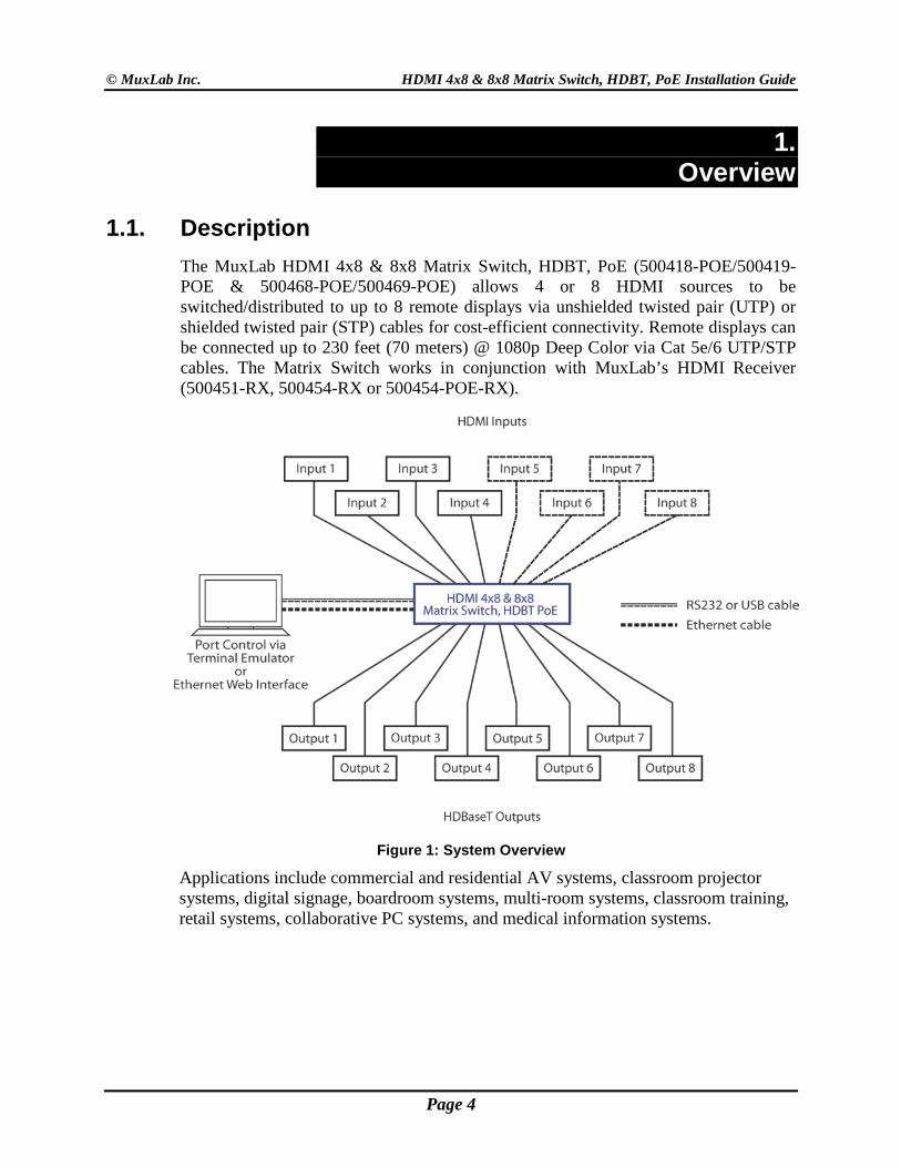
1.1. Description The MuxLab HDMI 4x8 & 8x8 Matrix Switch, HDBT, PoE (500418-POE/500419-POE & 500468-POE/500469-POE) allows 4 or 8 HDMI sources to be switched/distributed to up to 8 remote displays via unshielded twisted pair (UTP) or shielded twisted pair (STP) cables for cost-efficient connectivity. Remote displays can be connected up to 230 feet (70 meters) @ 1080p Deep Color via Cat 5e/6 UTP/STP cables. The Matrix Switch works in conjunction with MuxLab’s HDMI Receiver (500451-RX, 500454-RX or 500454-POE-RX).
Figure 1: System Overview Applications include commercial and residential AV systems, classroom projector systems, digital signage, boardroom systems, multi-room systems, classroom training, retail systems, collaborative PC systems, and medical information systems.
Page 4
© MuxLab Inc. HDMI 4x8 & 8x8 Matrix Switch, HDBT, PoE Installation Guide
1.2. Features • Single modular RJ45 jacks
• UTP/STP extension for 1080p Deep Color up to 230 feet (70 meters) via Cat 5e/6 UTP/STP cables
• HDMI 3D support
• Seamless integration with MuxLab’s HDMI Receiver (500451-RX, 500454-RX or 500454-POE-RX). Note: The 500451-RX doesn’t support RS-232 and PoE functionality.
• HDMI input supported with resolution up to 1080p
• HDBaseT supported output
• Configurable EDID settings
• Web interface
• RS232 and USB CDC control
• Firmware is field upgradable
• Touch pad on front panel for manual control
• Device control over HTTP protocol
• 2U rackmount unit
Page 5

© MuxLab Inc. HDMI 4x8 & 8x8 Matrix Switch, HDBT, PoE Installation Guide
2. Technical Specifications
4x8 & 8x8 Matrix Switch, HDBT, PoE Environment HDMI 1.4A 3D Support Devices LCD and Plasma TVs, DVD and Blu-Ray players, monitors, projectors, PCs, laptops,
home theatre systems, home theater PCs, game consoles. Transmission Transparent to the user Input Four (4) or Eight (8) HDMI and eight (8) IR Sensor (3.5 mm stereo) Output Eight (8) HDBaseT (RJ45) and four (4) or eight (8) IR Emitter (3.5 mm mono) Connectivity Ethernet LAN (RJ45), USB (Type B) and RS232 (DB9) Maximum Distance UTP/STP Cat 5e/6 output port: 230 feet (70 meters) Cables Cat 5e/6 UTP/STP cables (or better) required for HDBaseT port Power 100-240 VAC 50/60Hz, 0.72 A Matrix Switching Time 3 seconds (maximum) LED Diagnostics Power (Blue)
LAN (Link (Green) and Activity (Yellow)) Temperature Operating: 0ºC to 40ºC
Storage: –20ºC to 85ºC Humidity: Up to 95% non-condensing
Dimensions 2U Rack Mountable: 19 x 13.6 x 3.5 in (483 x 345 x 88 mm) Accessories Included 1 IR Sensor, 4 or 8 IR Emitters, Remote, USB Cable, RS232 Cable Shipping Weight 21.6 lbs (9.8 kg) Regulatory FCC, CE, RoHS, WEEE Warranty Two (2) years Order Information 500418-POE-US (UPC: 627699014185) HDMI 4x8 Matrix Switch, HDBT
500418-POE-UK (UPC: 627699914188) HDMI 4x8 Matrix Switch, HDBT 500418-POE-EU (UPC: 627699814181) HDMI 4x8 Matrix Switch, HDBT 500419-POE-US (UPC: 627699014196) HDMI 4x8 Matrix Switch, 4HDMI+4HDBT 500419-POE-UK (UPC: 627699914199) HDMI 4x8 Matrix Switch, 4HDMI+4HDBT 500419-POE-EU (UPC: 627699814192) HDMI 4x8 Matrix Switch, 4HDMI+4HDBT 500468-POE-US (UPC: 627699014684) HDMI 8x8 Matrix Switch, 4HDMI+4HDBT 500468-POE-UK (UPC: 627699914687) HDMI 8x8 Matrix Switch, 4HDMI+4HDBT 500468-POE-EU (UPC: 627699814680) HDMI 8x8 Matrix Switch, 4HDMI+4HDBT 500469-POE-US (UPC: 627699014691) HDMI 8x8 Matrix Switch, HDBT 500469-POE-UK (UPC: 627699914694) HDMI 8x8 Matrix Switch, HDBT 500469-POE-EU (UPC: 627699814697) HDMI 8x8 Matrix Switch, HDBT
Table 1: Technical Specifications
Page 6
© MuxLab Inc. HDMI 4x8 & 8x8 Matrix Switch, HDBT, PoE Installation Guide
3. Installation Procedure
3.1. Part List The HDMI 4x8 & 8x8 Matrix Switch, HDBT, PoE (500418-POE, 500419-POE, 500468-POE & 500469-POE) comes with the following parts:
• Base unit • Four (4) or Eight (8) IR Emitters • One (1) IR Sensor • Two (2) Brackets with screws • Power Cord (US, EU or UK) • One (1) USB Type A - Type B Cable • One (1) RS232 Cable • One (1) Infrared remote • One (1) Quick Reference Sheet
Please verify that all parts are present before proceeding.
Page 7
© MuxLab Inc. HDMI 4x8 & 8x8 Matrix Switch, HDBT, PoE Installation Guide
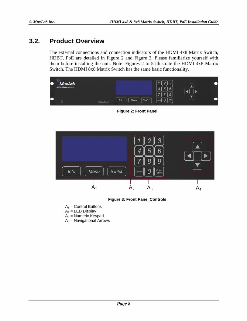
3.2. Product Overview The external connections and connection indicators of the HDMI 4x8 Matrix Switch, HDBT, PoE are detailed in Figure 2 and Figure 3. Please familiarize yourself with them before installing the unit. Note: Figures 2 to 5 illustrate the HDMI 4x8 Matrix Switch. The HDMI 8x8 Matrix Switch has the same basic functionality.
Figure 2: Front Panel
Figure 3: Front Panel Controls
A1 = Control Buttons A2 = LED Display A3 = Numeric Keypad A4 = Navigational Arrows
Page 8
© MuxLab Inc. HDMI 4x8 & 8x8 Matrix Switch, HDBT, PoE Installation Guide
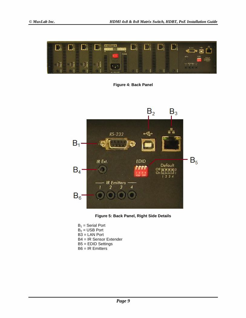
Figure 4: Back Panel
Figure 5: Back Panel, Right Side Details
B1 = Serial Port B2 = USB Port B3 = LAN Port B4 = IR Sensor Extender B5 = EDID Settings B6 = IR Emitters
Page 9
© MuxLab Inc. HDMI 4x8 & 8x8 Matrix Switch, HDBT, PoE Installation Guide
3.3. Pre-Installation Checklist The HDMI 4x8 & 8x8 Matrix Switch, HDBT, PoE provides a centralized HDMI switching center via UTP/STP cables.
1. The Matrix Switch is used in conjunction with MuxLab’s UTP/STP HDMI Receivers (500451-RX, 500454-RX or 500454-POE-RX).
2. The Matrix Switch is typically installed in a remote telecom room and is connected to multiple video sources and display devices via Cat 5e/6 UTP/STP or HDMI cables. A MuxLab Receiver is installed at each display to support the connection to the Matrix Switch via a Cat 5e/6 cable.
Page 10
© MuxLab Inc. HDMI 4x8 & 8x8 Matrix Switch, HDBT, PoE Installation Guide
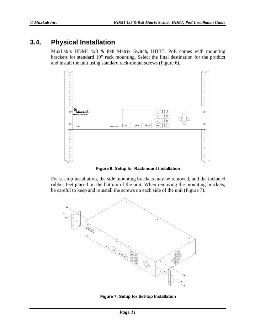
3.4. Physical Installation MuxLab’s HDMI 4x8 & 8x8 Matrix Switch, HDBT, PoE comes with mounting brackets for standard 19” rack mounting. Select the final destination for the product and install the unit using standard rack-mount screws (Figure 6).
Figure 6: Setup for Rackmount Installation
For set-top installation, the side mounting brackets may be removed, and the included rubber feet placed on the bottom of the unit. When removing the mounting brackets, be careful to keep and reinstall the screws on each side of the unit (Figure 7).
Figure 7: Setup for Set-top Installation
Page 11

© MuxLab Inc. HDMI 4x8 & 8x8 Matrix Switch, HDBT, PoE Installation Guide
3.5. Installation Procedure In order to install the HDMI 4x8 & 8x8 Matrix Switch, HDBT,PoE, please follow the steps below:
1. Place the Matrix Switch in its final location (see Section 3.4 Physical Installation). 2. Ensure that power is OFF on all sources and displays. 3. Using HDMI cables (not included), connect each source to an HDMI IN port on
the back panel of the Matrix Switch. 4. Ensure that one MuxLab Receiver is connected to each display using an HDMI
cable (not included). For more information, refer to MuxLab’s 500454 Quick Installation Guide.
5. Using Cat 5e/6 UTP/STP cables (not included) connect each MuxLab Receiver to an HDBT OUT port on the back panel of the Matrix Switch.
6. OPTIONAL: • Using an RS232 or USB cable, connect a computer to the corresponding port
on the back panel of the Matrix Switch. • Using an Ethernet cable, connect the Matrix Switch to the local area network. • Connect an RS232 cable (not included) between the RS232 port on the
MuxLab Receiver and the RS232 port on the display. • Connect IR sensors and emitters as needed. For more information, refer to
Figures 5 and 6. NOTE: IR Sensor cables are equipped with a 3.5 mm stereo jack, and IR Emitter cables are equipped with a 3.5 mm mono jack.
7. Power up the MuxLab Receivers and HDMI equipment. 8. Plug the power cord into an AC power outlet and turn on the power by using the
Power Switch located on the back of the unit. If power is present, the blue power LED will be illuminated.
9. Ensure that the source and appropriate display LEDs are ON. Images should appear on the displays within 10 seconds. For signal or image quality problems, refer to Section 4 Troubleshooting.
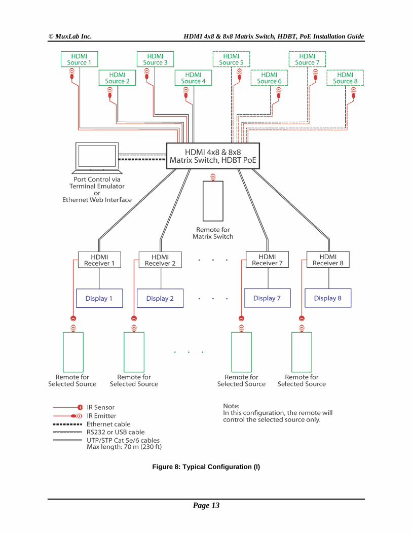
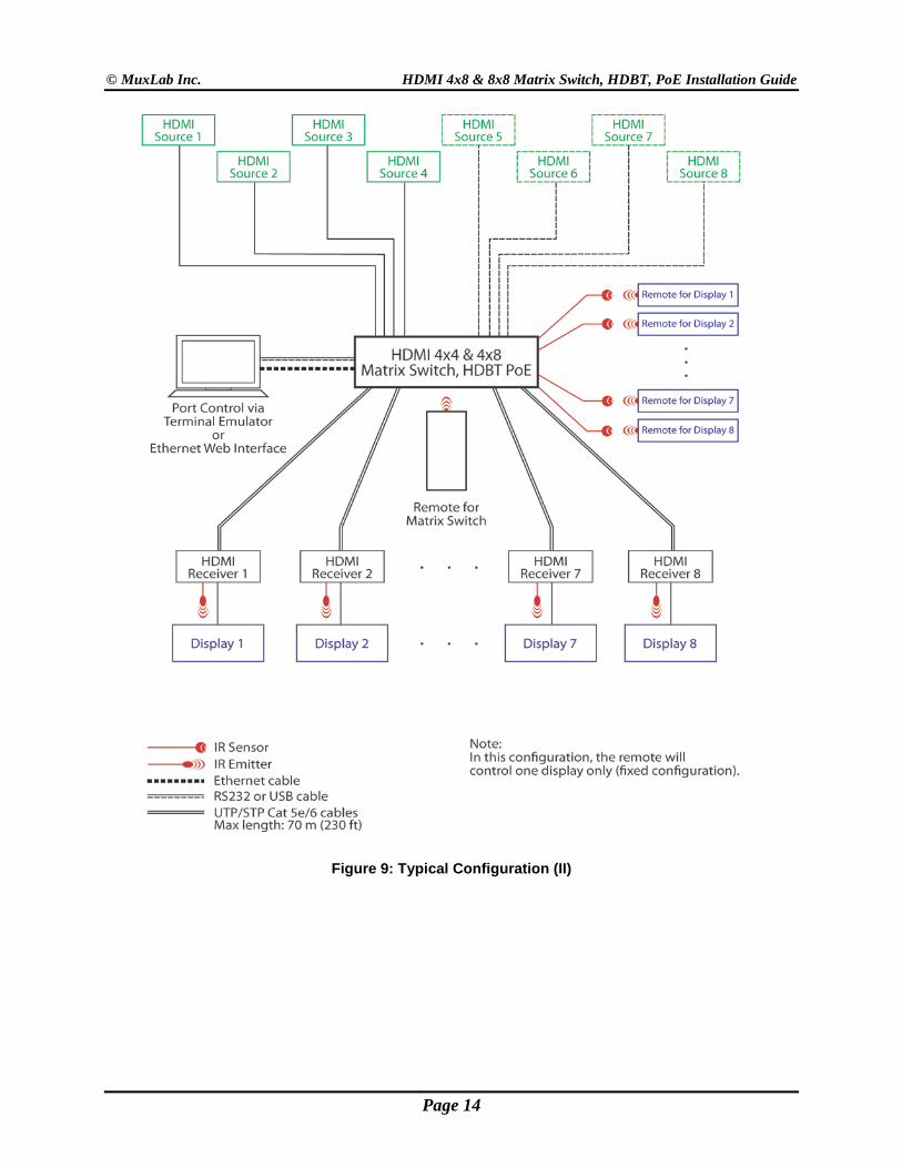
10. Figures 8 and 9 show some typical configurations.
The Matrix Switch is now ready to use. See Section 3.7 Manual Control for instructions on usage.
Page 12
© MuxLab Inc. HDMI 4x8 & 8x8 Matrix Switch, HDBT, PoE Installation Guide
Figure 8: Typical Configuration (I)
Page 13
© MuxLab Inc. HDMI 4x8 & 8x8 Matrix Switch, HDBT, PoE Installation Guide
Figure 9: Typical Configuration (II)
Page 14
© MuxLab Inc. HDMI 4x8 & 8x8 Matrix Switch, HDBT, PoE Installation Guide
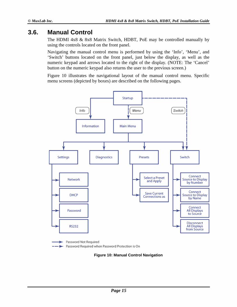
3.6. Manual Control The HDMI 4x8 & 8x8 Matrix Switch, HDBT, PoE may be controlled manually by using the controls located on the front panel. Navigating the manual control menu is performed by using the ‘Info’, ‘Menu’, and ‘Switch’ buttons located on the front panel, just below the display, as well as the numeric keypad and arrows located to the right of the display. (NOTE: The ‘Cancel’ button on the numeric keypad also returns the user to the previous screen.)
Figure 10 illustrates the navigational layout of the manual control menu. Specific menu screens (depicted by boxes) are described on the following pages.
Figure 10: Manual Control Navigation
Page 15
© MuxLab Inc. HDMI 4x8 & 8x8 Matrix Switch, HDBT, PoE Installation Guide
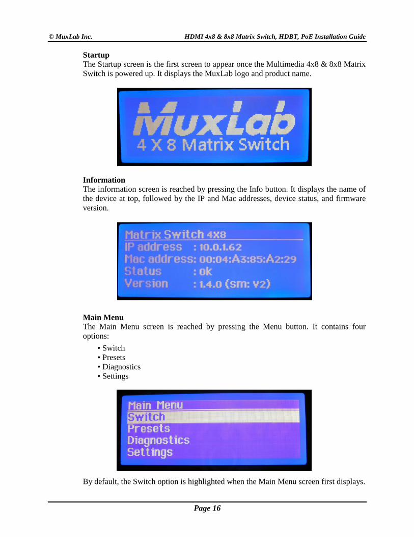
Startup The Startup screen is the first screen to appear once the Multimedia 4x8 & 8x8 Matrix Switch is powered up. It displays the MuxLab logo and product name.
Information The information screen is reached by pressing the Info button. It displays the name of the device at top, followed by the IP and Mac addresses, device status, and firmware version.
Main Menu The Main Menu screen is reached by pressing the Menu button. It contains four options: • Switch • Presets • Diagnostics • Settings
By default, the Switch option is highlighted when the Main Menu screen first displays.
Page 16
© MuxLab Inc. HDMI 4x8 & 8x8 Matrix Switch, HDBT, PoE Installation Guide
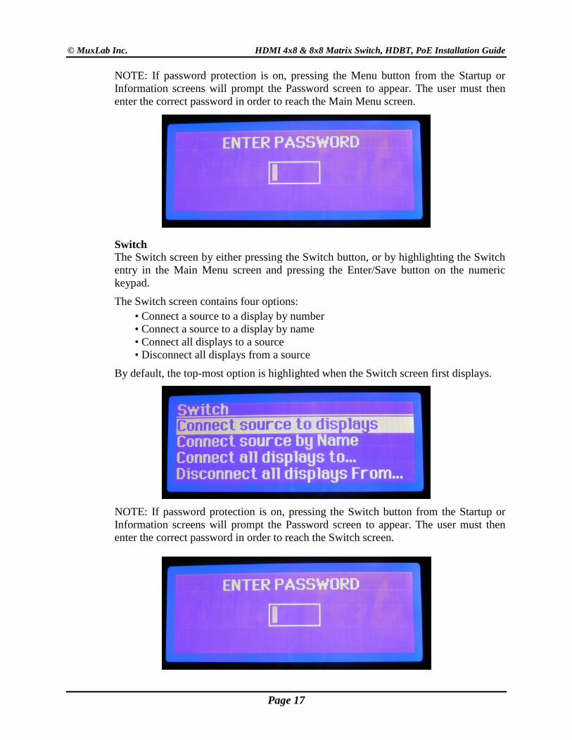
NOTE: If password protection is on, pressing the Menu button from the Startup or Information screens will prompt the Password screen to appear. The user must then enter the correct password in order to reach the Main Menu screen.
Switch The Switch screen by either pressing the Switch button, or by highlighting the Switch entry in the Main Menu screen and pressing the Enter/Save button on the numeric keypad.
The Switch screen contains four options: • Connect a source to a display by number • Connect a source to a display by name • Connect all displays to a source • Disconnect all displays from a source
By default, the top-most option is highlighted when the Switch screen first displays.
NOTE: If password protection is on, pressing the Switch button from the Startup or Information screens will prompt the Password screen to appear. The user must then enter the correct password in order to reach the Switch screen.
Page 17
© MuxLab Inc. HDMI 4x8 & 8x8 Matrix Switch, HDBT, PoE Installation Guide
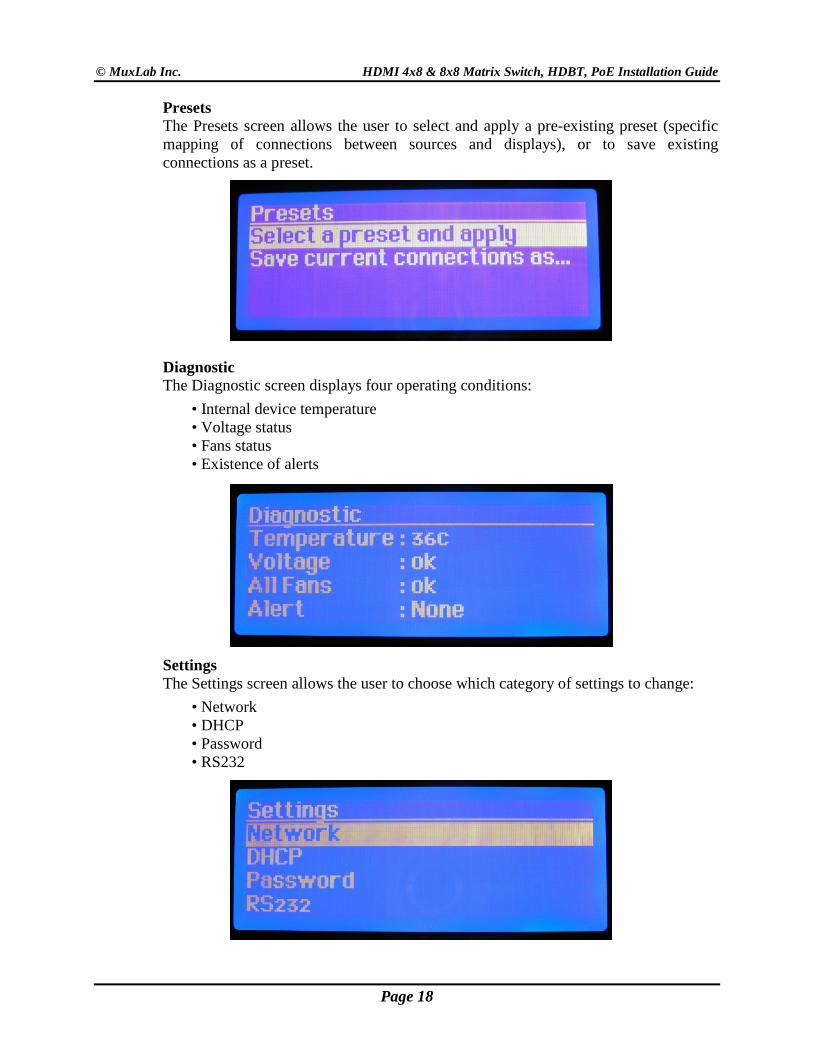
Presets The Presets screen allows the user to select and apply a pre-existing preset (specific mapping of connections between sources and displays), or to save existing connections as a preset.
Diagnostic The Diagnostic screen displays four operating conditions: • Internal device temperature • Voltage status • Fans status • Existence of alerts
Settings The Settings screen allows the user to choose which category of settings to change:
• Network • DHCP • Password • RS232
Page 18
© MuxLab Inc. HDMI 4x8 & 8x8 Matrix Switch, HDBT, PoE Installation Guide
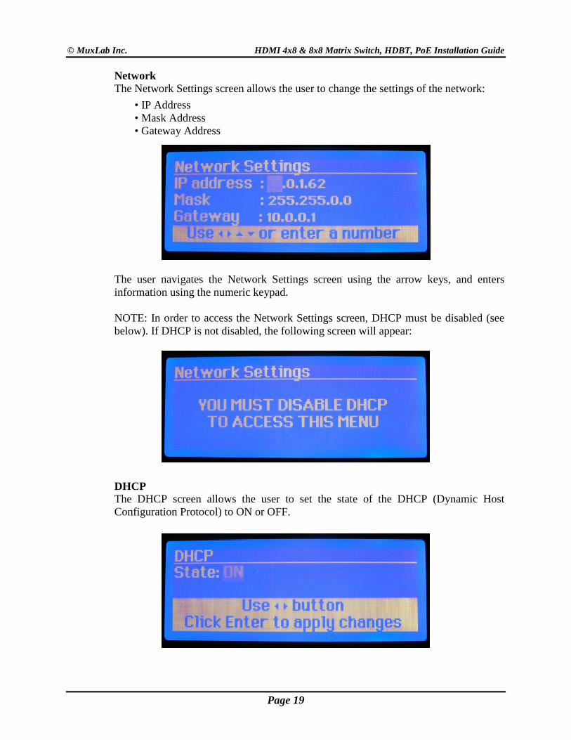
Network The Network Settings screen allows the user to change the settings of the network:
• IP Address • Mask Address • Gateway Address
The user navigates the Network Settings screen using the arrow keys, and enters information using the numeric keypad. NOTE: In order to access the Network Settings screen, DHCP must be disabled (see below). If DHCP is not disabled, the following screen will appear:
DHCP The DHCP screen allows the user to set the state of the DHCP (Dynamic Host Configuration Protocol) to ON or OFF.
Page 19
© MuxLab Inc. HDMI 4x8 & 8x8 Matrix Switch, HDBT, PoE Installation Guide
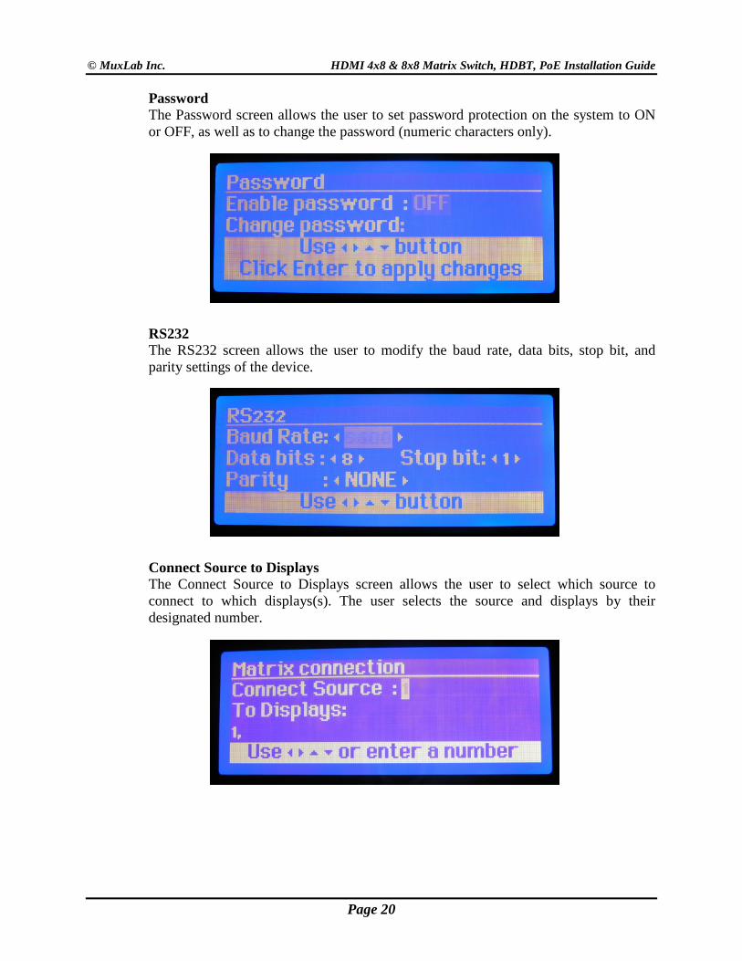
Password The Password screen allows the user to set password protection on the system to ON or OFF, as well as to change the password (numeric characters only).
RS232 The RS232 screen allows the user to modify the baud rate, data bits, stop bit, and parity settings of the device.
Connect Source to Displays The Connect Source to Displays screen allows the user to select which source to connect to which displays(s). The user selects the source and displays by their designated number.
Page 20
© MuxLab Inc. HDMI 4x8 & 8x8 Matrix Switch, HDBT, PoE Installation Guide
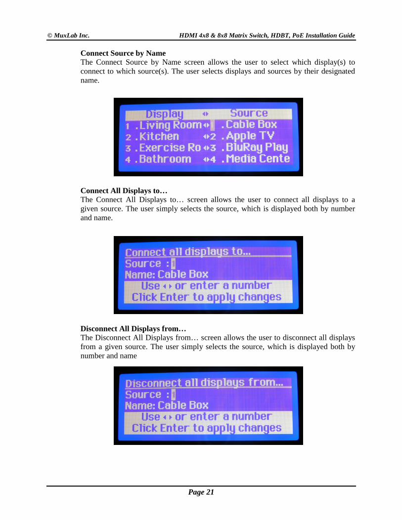
Connect Source by Name The Connect Source by Name screen allows the user to select which display(s) to connect to which source(s). The user selects displays and sources by their designated name.
Connect All Displays to… The Connect All Displays to… screen allows the user to connect all displays to a given source. The user simply selects the source, which is displayed both by number and name.
Disconnect All Displays from… The Disconnect All Displays from… screen allows the user to disconnect all displays from a given source. The user simply selects the source, which is displayed both by number and name
Page 21
© MuxLab Inc. HDMI 4x8 & 8x8 Matrix Switch, HDBT, PoE Installation Guide
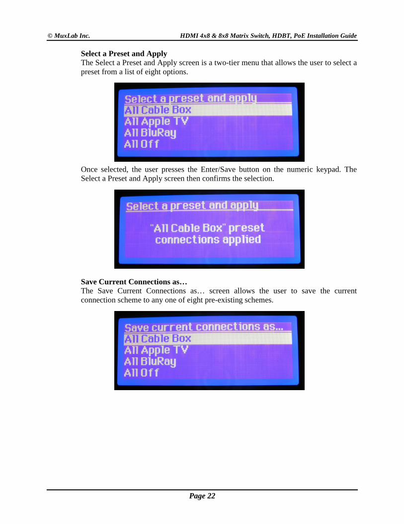
Select a Preset and Apply The Select a Preset and Apply screen is a two-tier menu that allows the user to select a preset from a list of eight options.
Once selected, the user presses the Enter/Save button on the numeric keypad. The Select a Preset and Apply screen then confirms the selection.
Save Current Connections as… The Save Current Connections as… screen allows the user to save the current connection scheme to any one of eight pre-existing schemes.
Page 22
© MuxLab Inc. HDMI 4x8 & 8x8 Matrix Switch, HDBT, PoE Installation Guide
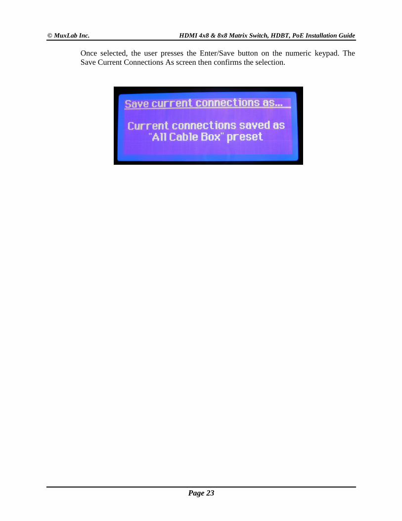
Once selected, the user presses the Enter/Save button on the numeric keypad. The Save Current Connections As screen then confirms the selection.
Page 23
© MuxLab Inc. HDMI 4x8 & 8x8 Matrix Switch, HDBT, PoE Installation Guide
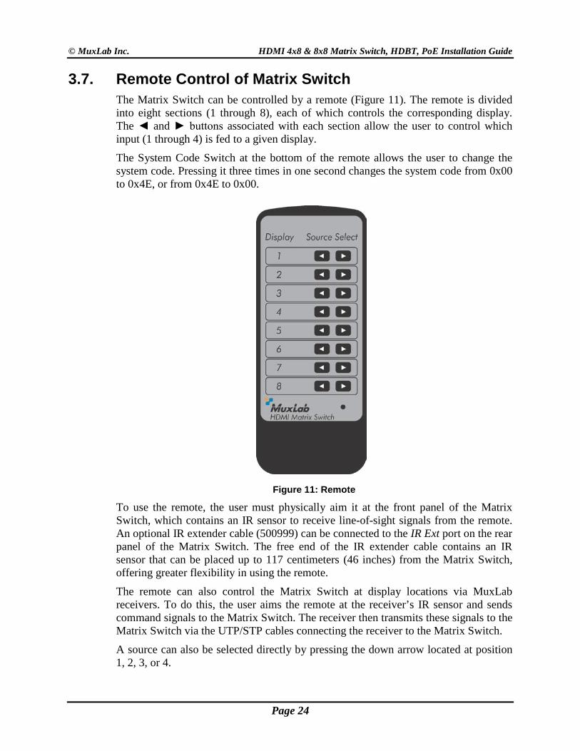
3.7. Remote Control of Matrix Switch The Matrix Switch can be controlled by a remote (Figure 11). The remote is divided into eight sections (1 through 8), each of which controls the corresponding display. The ◄ and ► buttons associated with each section allow the user to control which input (1 through 4) is fed to a given display.
The System Code Switch at the bottom of the remote allows the user to change the system code. Pressing it three times in one second changes the system code from 0x00 to 0x4E, or from 0x4E to 0x00.
Figure 11: Remote
To use the remote, the user must physically aim it at the front panel of the Matrix Switch, which contains an IR sensor to receive line-of-sight signals from the remote. An optional IR extender cable (500999) can be connected to the IR Ext port on the rear panel of the Matrix Switch. The free end of the IR extender cable contains an IR sensor that can be placed up to 117 centimeters (46 inches) from the Matrix Switch, offering greater flexibility in using the remote.
The remote can also control the Matrix Switch at display locations via MuxLab receivers. To do this, the user aims the remote at the receiver’s IR sensor and sends command signals to the Matrix Switch. The receiver then transmits these signals to the Matrix Switch via the UTP/STP cables connecting the receiver to the Matrix Switch.
A source can also be selected directly by pressing the down arrow located at position 1, 2, 3, or 4.
Page 24
© MuxLab Inc. HDMI 4x8 & 8x8 Matrix Switch, HDBT, PoE Installation Guide
3.8. Remote Control of Sources and Displays Sources and displays do not have to be controlled at their physical location. Using MuxLab receivers, each source and display can be controlled at different locations using their respective remotes.
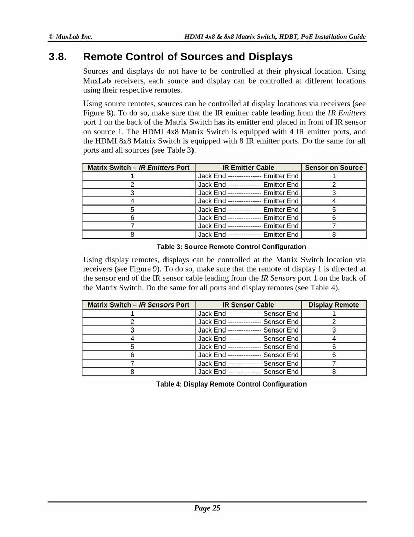
Using source remotes, sources can be controlled at display locations via receivers (see Figure 8). To do so, make sure that the IR emitter cable leading from the IR Emitters port 1 on the back of the Matrix Switch has its emitter end placed in front of IR sensor on source 1. The HDMI 4x8 Matrix Switch is equipped with 4 IR emitter ports, and the HDMI 8x8 Matrix Switch is equipped with 8 IR emitter ports. Do the same for all ports and all sources (see Table 3).
Matrix Switch – IR Emitters Port IR Emitter Cable Sensor on Source 1 Jack End --------------- Emitter End 1 2 Jack End --------------- Emitter End 2 3 Jack End --------------- Emitter End 3 4 Jack End --------------- Emitter End 4 5 Jack End --------------- Emitter End 5 6 Jack End --------------- Emitter End 6 7 Jack End --------------- Emitter End 7 8 Jack End --------------- Emitter End 8
Table 3: Source Remote Control Configuration
Using display remotes, displays can be controlled at the Matrix Switch location via receivers (see Figure 9). To do so, make sure that the remote of display 1 is directed at the sensor end of the IR sensor cable leading from the IR Sensors port 1 on the back of the Matrix Switch. Do the same for all ports and display remotes (see Table 4).
Matrix Switch – IR Sensors Port IR Sensor Cable Display Remote 1 Jack End --------------- Sensor End 1 2 Jack End --------------- Sensor End 2 3 Jack End --------------- Sensor End 3 4 Jack End --------------- Sensor End 4 5 Jack End --------------- Sensor End 5 6 Jack End --------------- Sensor End 6 7 Jack End --------------- Sensor End 7 8 Jack End --------------- Sensor End 8
Table 4: Display Remote Control Configuration
Page 25
© MuxLab Inc. HDMI 4x8 & 8x8 Matrix Switch, HDBT, PoE Installation Guide
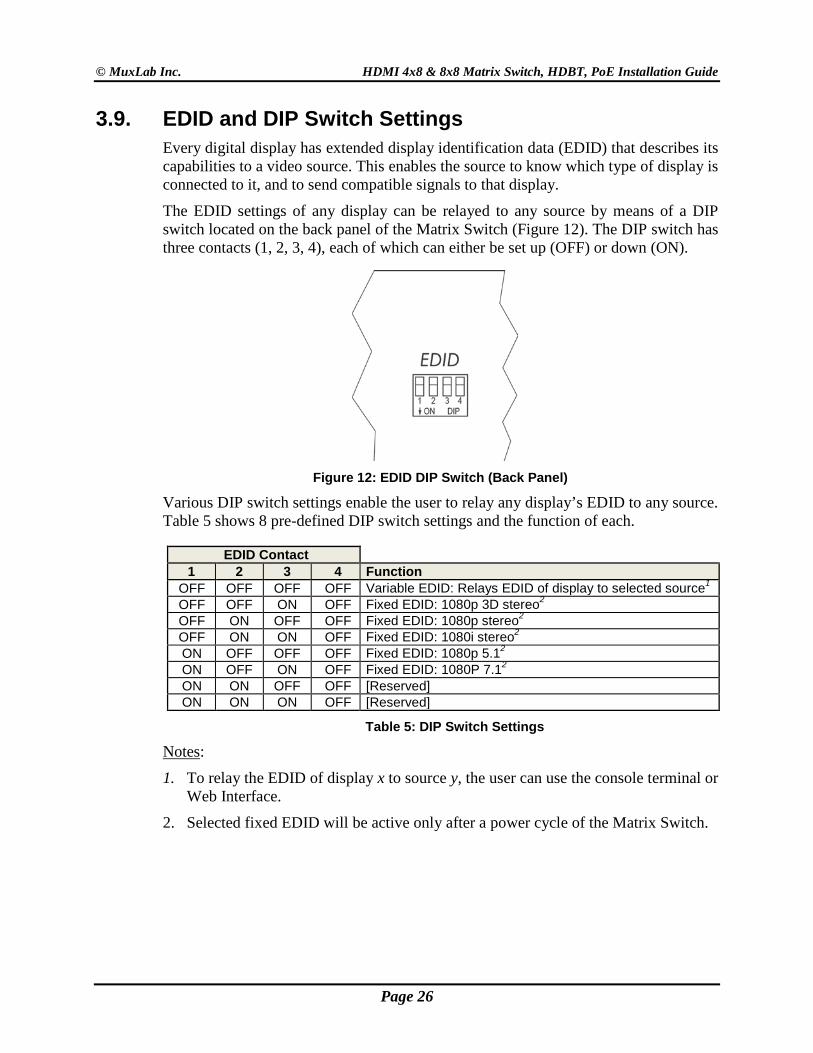
3.9. EDID and DIP Switch Settings Every digital display has extended display identification data (EDID) that describes its capabilities to a video source. This enables the source to know which type of display is connected to it, and to send compatible signals to that display.
The EDID settings of any display can be relayed to any source by means of a DIP switch located on the back panel of the Matrix Switch (Figure 12). The DIP switch has three contacts (1, 2, 3, 4), each of which can either be set up (OFF) or down (ON).
Figure 12: EDID DIP Switch (Back Panel) Various DIP switch settings enable the user to relay any display’s EDID to any source. Table 5 shows 8 pre-defined DIP switch settings and the function of each.
EDID Contact 1 2 3 4 Function
OFF OFF OFF OFF Variable EDID: Relays EDID of display to selected source1 OFF OFF ON OFF Fixed EDID: 1080p 3D stereo2 OFF ON OFF OFF Fixed EDID: 1080p stereo2 OFF ON ON OFF Fixed EDID: 1080i stereo2 ON OFF OFF OFF Fixed EDID: 1080p 5.12 ON OFF ON OFF Fixed EDID: 1080P 7.12 ON ON OFF OFF [Reserved] ON ON ON OFF [Reserved]
Table 5: DIP Switch Settings
Notes:
1. To relay the EDID of display x to source y, the user can use the console terminal or Web Interface.
2. Selected fixed EDID will be active only after a power cycle of the Matrix Switch.
Page 26
© MuxLab Inc. HDMI 4x8 & 8x8 Matrix Switch, HDBT, PoE Installation Guide
3.10. Port Control Operation MuxLab’s HDMI 4x8 & 8x8 Matrix Switch, HDBT PoE may be controlled in any one of two ways:
1. RS-232 Control 2. USB CDC Control
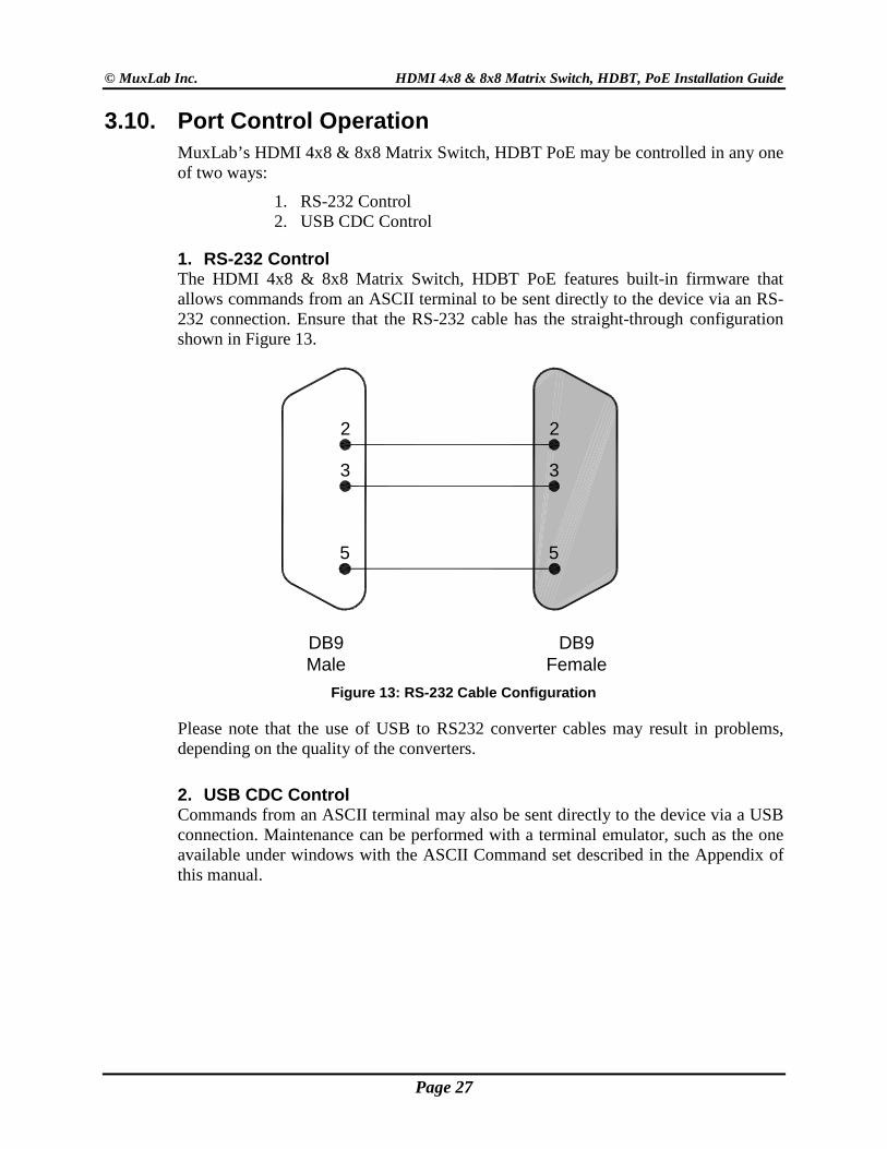
1. RS-232 Control The HDMI 4x8 & 8x8 Matrix Switch, HDBT PoE features built-in firmware that allows commands from an ASCII terminal to be sent directly to the device via an RS-232 connection. Ensure that the RS-232 cable has the straight-through configuration shown in Figure 13.
Figure 13: RS-232 Cable Configuration
Please note that the use of USB to RS232 converter cables may result in problems, depending on the quality of the converters.
2. USB CDC Control Commands from an ASCII terminal may also be sent directly to the device via a USB connection. Maintenance can be performed with a terminal emulator, such as the one available under windows with the ASCII Command set described in the Appendix of this manual.
2
3
5
2
3
5
DB9Male
DB9Female
Page 27
© MuxLab Inc. HDMI 4x8 & 8x8 Matrix Switch, HDBT, PoE Installation Guide
3.11. USB Driver Setup When interfacing a MuxLab device with the USB port on Windows XP, Windows 7, or Windows 8 operating systems, a driver setup file will be required. For Linux and Mac OS X operating systems, no driver is necessary.
To install the USB serial driver, download the SC-000032-A USB to serial driver file from the MuxLab website and save it to the local hard drive. NOTE: If the downloaded file is compressed, it will have to be uncompressed before using it.
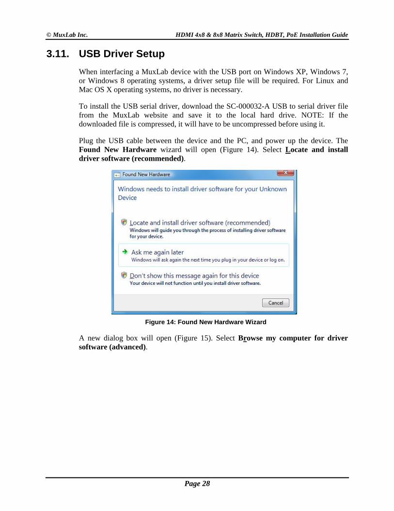
Plug the USB cable between the device and the PC, and power up the device. The Found New Hardware wizard will open (Figure 14). Select Locate and install driver software (recommended).
Figure 14: Found New Hardware Wizard
A new dialog box will open (Figure 15). Select Browse my computer for driver software (advanced).
Page 28
© MuxLab Inc. HDMI 4x8 & 8x8 Matrix Switch, HDBT, PoE Installation Guide
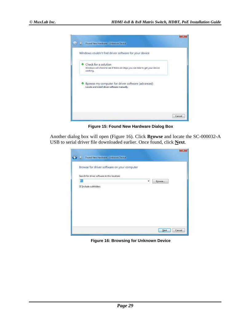
Figure 15: Found New Hardware Dialog Box
Another dialog box will open (Figure 16). Click Browse and locate the SC-000032-A USB to serial driver file downloaded earlier. Once found, click Next.
Figure 16: Browsing for Unknown Device
Page 29
© MuxLab Inc. HDMI 4x8 & 8x8 Matrix Switch, HDBT, PoE Installation Guide
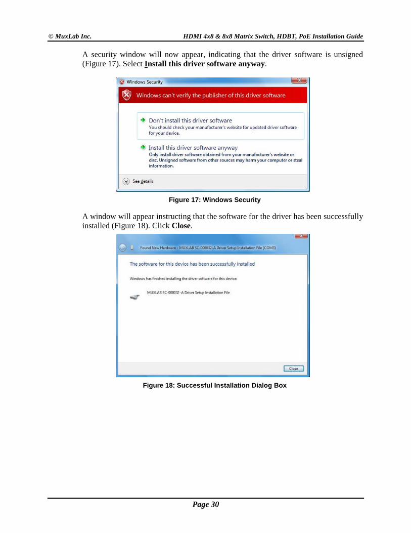
A security window will now appear, indicating that the driver software is unsigned (Figure 17). Select Install this driver software anyway.
Figure 17: Windows Security
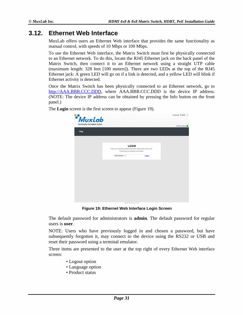
A window will appear instructing that the software for the driver has been successfully installed (Figure 18). Click Close.
Figure 18: Successful Installation Dialog Box
Page 30
© MuxLab Inc. HDMI 4x8 & 8x8 Matrix Switch, HDBT, PoE Installation Guide
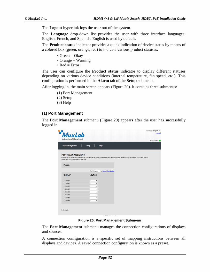
3.12. Ethernet Web Interface MuxLab offers users an Ethernet Web interface that provides the same functionality as manual control, with speeds of 10 Mbps or 100 Mbps. To use the Ethernet Web interface, the Matrix Switch must first be physically connected to an Ethernet network. To do this, locate the RJ45 Ethernet jack on the back panel of the Matrix Switch, then connect it to an Ethernet network using a straight UTP cable (maximum length: 328 feet [100 meters]). There are two LEDs at the top of the RJ45 Ethernet jack: A green LED will go on if a link is detected, and a yellow LED will blink if Ethernet activity is detected. Once the Matrix Switch has been physically connected to an Ethernet network, go to http://AAA.BBB.CCC.DDD, where AAA.BBB.CCC.DDD is the device IP address. (NOTE: The device IP address can be obtained by pressing the Info button on the front panel.) The Login screen is the first screen to appear (Figure 19).
Figure 19: Ethernet Web Interface Login Screen
The default password for administrators is admin. The default password for regular users is user. NOTE: Users who have previously logged in and chosen a password, but have subsequently forgotten it, may connect to the device using the RS232 or USB and reset their password using a terminal emulator. Three items are presented to the user at the top right of every Ethernet Web interface screen:
• Logout option • Language option • Product status
Page 31
© MuxLab Inc. HDMI 4x8 & 8x8 Matrix Switch, HDBT, PoE Installation Guide
The Logout hyperlink logs the user out of the system. The Language drop-down list provides the user with three interface languages: English, French, and Spanish. English is used by default. The Product status indicator provides a quick indication of device status by means of a colored box (green, orange, red) to indicate various product statuses:
• Green = Okay • Orange = Warning • Red = Error
The user can configure the Product status indicator to display different statuses depending on various device conditions (internal temperature, fan speed, etc.). This configuration is performed in the Alarm tab of the Setup submenu. After logging in, the main screen appears (Figure 20). It contains three submenus:
(1) Port Management (2) Setup (3) Help
(1) Port Management The Port Management submenu (Figure 20) appears after the user has successfully logged in.
Figure 20: Port Management Submenu
The Port Management submenu manages the connection configurations of displays and sources.
A connection configuration is a specific set of mapping instructions between all displays and devices. A saved connection configuration is known as a preset.
Page 32
© MuxLab Inc. HDMI 4x8 & 8x8 Matrix Switch, HDBT, PoE Installation Guide
The Port Management submenu allows the user to make individual connections between specific displays and sources, or wholesale connections between all displays and sources by means of presets. Sources and displays are presented to the user in any one of four ways:
• By source name • By source number • By display name • By display number
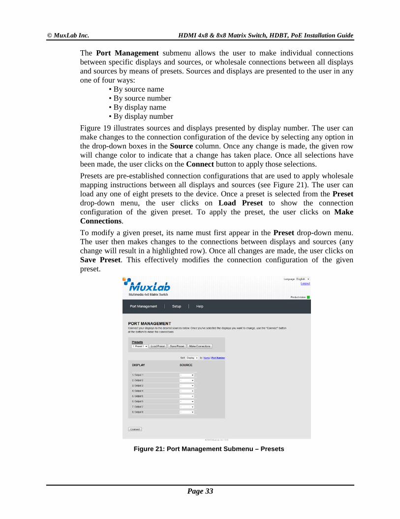
Figure 19 illustrates sources and displays presented by display number. The user can make changes to the connection configuration of the device by selecting any option in the drop-down boxes in the Source column. Once any change is made, the given row will change color to indicate that a change has taken place. Once all selections have been made, the user clicks on the Connect button to apply those selections. Presets are pre-established connection configurations that are used to apply wholesale mapping instructions between all displays and sources (see Figure 21). The user can load any one of eight presets to the device. Once a preset is selected from the Preset drop-down menu, the user clicks on Load Preset to show the connection configuration of the given preset. To apply the preset, the user clicks on Make Connections. To modify a given preset, its name must first appear in the Preset drop-down menu. The user then makes changes to the connections between displays and sources (any change will result in a highlighted row). Once all changes are made, the user clicks on Save Preset. This effectively modifies the connection configuration of the given preset.
Figure 21: Port Management Submenu – Presets
Page 33
© MuxLab Inc. HDMI 4x8 & 8x8 Matrix Switch, HDBT, PoE Installation Guide
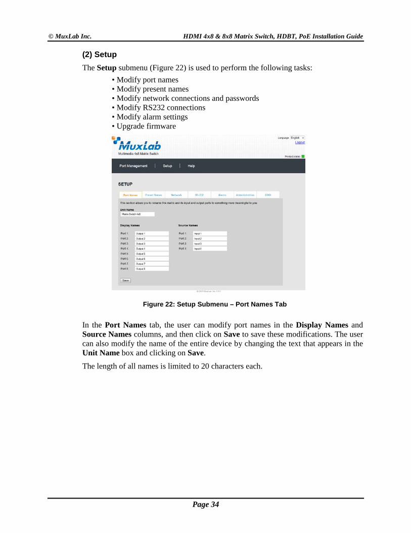
(2) Setup The Setup submenu (Figure 22) is used to perform the following tasks:
• Modify port names • Modify present names • Modify network connections and passwords • Modify RS232 connections • Modify alarm settings • Upgrade firmware
Figure 22: Setup Submenu – Port Names Tab
In the Port Names tab, the user can modify port names in the Display Names and Source Names columns, and then click on Save to save these modifications. The user can also modify the name of the entire device by changing the text that appears in the Unit Name box and clicking on Save.
The length of all names is limited to 20 characters each.
Page 34
© MuxLab Inc. HDMI 4x8 & 8x8 Matrix Switch, HDBT, PoE Installation Guide
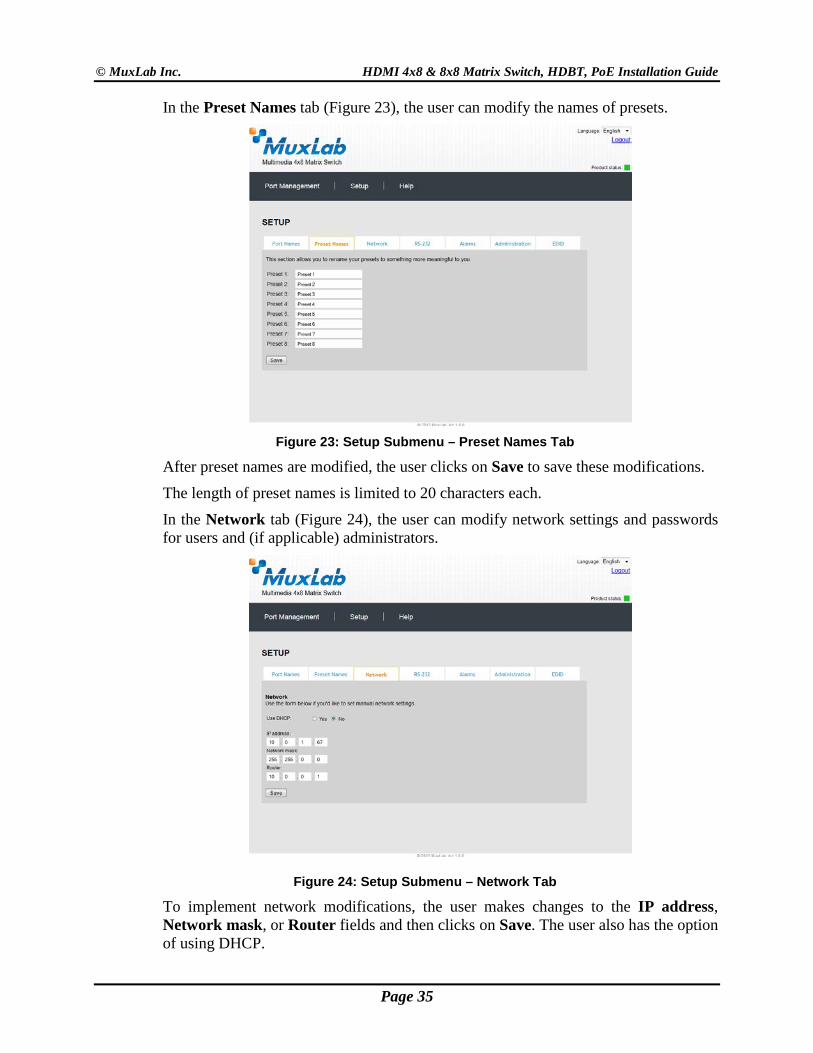
In the Preset Names tab (Figure 23), the user can modify the names of presets.
Figure 23: Setup Submenu – Preset Names Tab
After preset names are modified, the user clicks on Save to save these modifications.
The length of preset names is limited to 20 characters each.
In the Network tab (Figure 24), the user can modify network settings and passwords for users and (if applicable) administrators.
Figure 24: Setup Submenu – Network Tab
To implement network modifications, the user makes changes to the IP address, Network mask, or Router fields and then clicks on Save. The user also has the option of using DHCP.
Page 35
© MuxLab Inc. HDMI 4x8 & 8x8 Matrix Switch, HDBT, PoE Installation Guide
To implement password modifications, an administrator makes changes to the Administrator Password and/or the User Password, and then clicks on the corresponding Save button. Regular users can only make changes to the User Password.
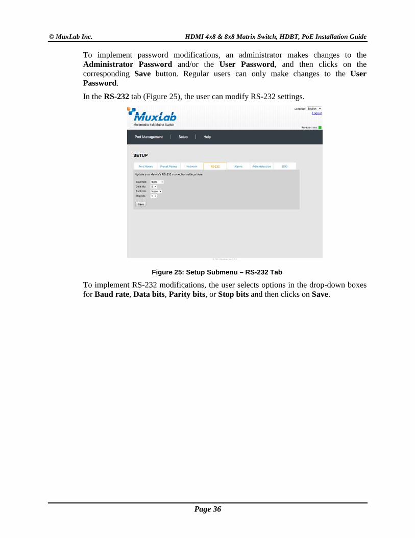
In the RS-232 tab (Figure 25), the user can modify RS-232 settings.
Figure 25: Setup Submenu – RS-232 Tab
To implement RS-232 modifications, the user selects options in the drop-down boxes for Baud rate, Data bits, Parity bits, or Stop bits and then clicks on Save.
Page 36
© MuxLab Inc. HDMI 4x8 & 8x8 Matrix Switch, HDBT, PoE Installation Guide
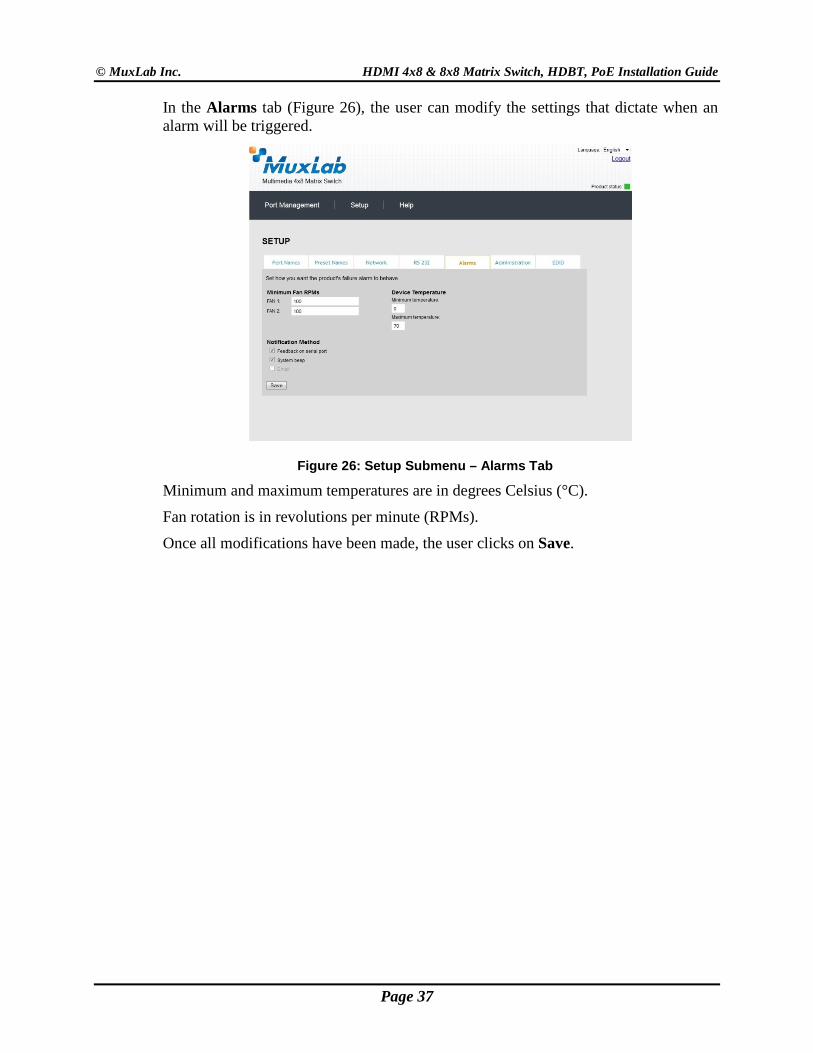
In the Alarms tab (Figure 26), the user can modify the settings that dictate when an alarm will be triggered.
Figure 26: Setup Submenu – Alarms Tab
Minimum and maximum temperatures are in degrees Celsius (°C).
Fan rotation is in revolutions per minute (RPMs).
Once all modifications have been made, the user clicks on Save.
Page 37
© MuxLab Inc. HDMI 4x8 & 8x8 Matrix Switch, HDBT, PoE Installation Guide
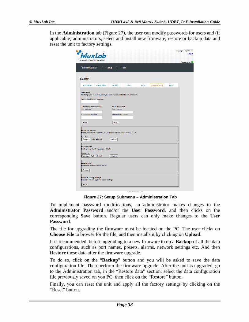
In the Administration tab (Figure 27), the user can modify passwords for users and (if applicable) administrators, select and install new firmware, restore or backup data and reset the unit to factory settings.
Figure 27: Setup Submenu – Administration Tab
To implement password modifications, an administrator makes changes to the Administrator Password and/or the User Password, and then clicks on the corresponding Save button. Regular users can only make changes to the User Password. The file for upgrading the firmware must be located on the PC. The user clicks on Choose File to browse for the file, and then installs it by clicking on Upload. It is recommended, before upgrading to a new firmware to do a Backup of all the data configurations, such as port names, presets, alarms, network settings etc. And then Restore these data after the firmware upgrade. To do so, click on the “Backup” button and you will be asked to save the data configuration file. Then perform the firmware upgrade. After the unit is upgraded, go to the Administration tab, in the “Restore data” section, select the data configuration file previously saved on you PC, then click on the “Restore” button. Finally, you can reset the unit and apply all the factory settings by clicking on the “Reset” button.
Page 38
© MuxLab Inc. HDMI 4x8 & 8x8 Matrix Switch, HDBT, PoE Installation Guide
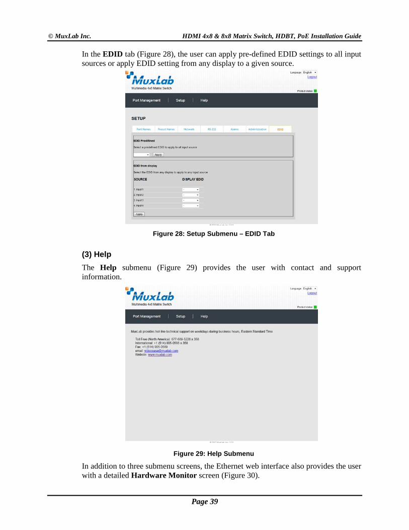
In the EDID tab (Figure 28), the user can apply pre-defined EDID settings to all input sources or apply EDID setting from any display to a given source.
Figure 28: Setup Submenu – EDID Tab
(3) Help The Help submenu (Figure 29) provides the user with contact and support information.
Figure 29: Help Submenu
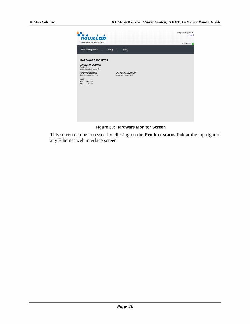
In addition to three submenu screens, the Ethernet web interface also provides the user with a detailed Hardware Monitor screen (Figure 30).
Page 39
© MuxLab Inc. HDMI 4x8 & 8x8 Matrix Switch, HDBT, PoE Installation Guide
Figure 30: Hardware Monitor Screen
This screen can be accessed by clicking on the Product status link at the top right of any Ethernet web interface screen.
Page 40
© MuxLab Inc. HDMI 4x8 & 8x8 Matrix Switch, HDBT, PoE Installation Guide
4. Troubleshooting
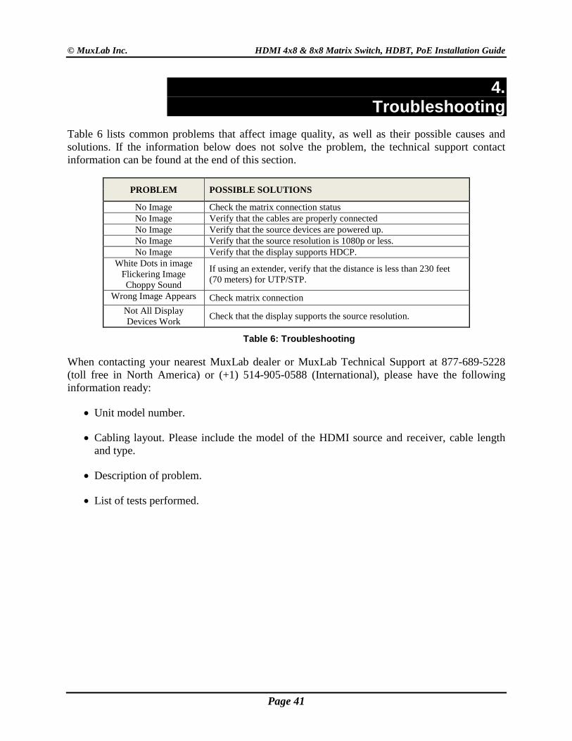
Table 6 lists common problems that affect image quality, as well as their possible causes and solutions. If the information below does not solve the problem, the technical support contact information can be found at the end of this section.
PROBLEM POSSIBLE SOLUTIONS
No Image Check the matrix connection status No Image Verify that the cables are properly connected No Image Verify that the source devices are powered up. No Image Verify that the source resolution is 1080p or less. No Image Verify that the display supports HDCP.
White Dots in image Flickering Image Choppy Sound
If using an extender, verify that the distance is less than 230 feet (70 meters) for UTP/STP.
Wrong Image Appears Check matrix connection Not All Display Devices Work Check that the display supports the source resolution.
Table 6: Troubleshooting
When contacting your nearest MuxLab dealer or MuxLab Technical Support at 877-689-5228 (toll free in North America) or (+1) 514-905-0588 (International), please have the following information ready:
• Unit model number.
• Cabling layout. Please include the model of the HDMI source and receiver, cable length and type.
• Description of problem.
• List of tests performed.
Page 41
© MuxLab Inc. HDMI 4x8 & 8x8 Matrix Switch, HDBT, PoE Installation Guide
5. Appendix
A. ASCII Command Set Ensure that the terminal emulation program parameters are set to the following:
BAUD Rate: 9600
Data bits: 8
Stop bits: 1
Parity: None
Flow control: None
It should be noted that commands are case sensitive and arguments must be separated by a single space. Commands must be entered in the following way and ended with a carriage return:
Page 42
© MuxLab Inc. HDMI 4x8 & 8x8 Matrix Switch, HDBT, PoE Installation Guide
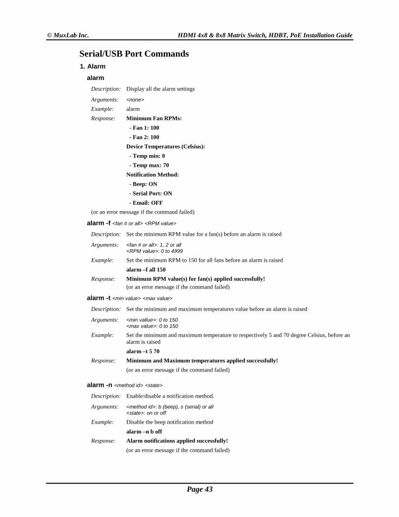
Serial/USB Port Commands 1. Alarm
alarm Description: Display all the alarm settings
Arguments: <none> Example: alarm
Response: Minimum Fan RPMs: - Fan 1: 100 - Fan 2: 100 Device Temperatures (Celsius): - Temp min: 0 - Temp max: 70 Notification Method: - Beep: ON - Serial Port: ON - Email: OFF (or an error message if the command failed)
alarm -f <fan # or all> <RPM value> Description: Set the minimum RPM value for a fan(s) before an alarm is raised
Arguments: <fan # or all>: 1, 2 or all <RPM value>: 0 to 4999
Example: Set the minimum RPM to 150 for all fans before an alarm is raised alarm –f all 150 Response: Minimum RPM value(s) for fan(s) applied successfully! (or an error message if the command failed)
alarm -t <min value> <max value> Description: Set the minimum and maximum temperatures value before an alarm is raised
Arguments: <min vallue>: 0 to 150 <max value>: 0 to 150
Example: Set the minimum and maximum temperature to respectively 5 and 70 degree Celsius, before an alarm is raised
alarm –t 5 70 Response: Minimum and Maximum temperatures applied successfully! (or an error message if the command failed)
alarm -n <method id> <state> Description: Enable/disable a notification method.
Arguments: <method id>: b (beep), s (serial) or all <state>: on or off
Example: Disable the beep notification method alarm –n b off Response: Alarm notifications applied successfully! (or an error message if the command failed)
Page 43
© MuxLab Inc. HDMI 4x8 & 8x8 Matrix Switch, HDBT, PoE Installation Guide
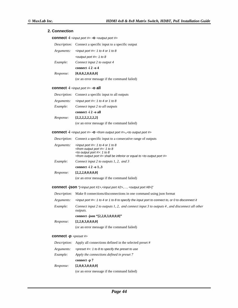
2. Connection
connect -i <input port #> -o <output port #> Description: Connect a specific input to a specific output
Arguments: <input port #>: 1 to 4 or 1 to 8
<output port #>: 1 to 8 Example: Connect input 2 to output 4 connect -i 2 -o 4 Response: [0,0,0,2,0,0,0,0] (or an error message if the command failed)
connect -i <input port #> -o all Description: Connect a specific input to all outputs
Arguments: <input port #>: 1 to 4 or 1 to 8
Example: Connect input 2 to all outputs connect -i 2 -o all Response: [2,2,2,2,2,2,2,2] (or an error message if the command failed)
connect -i <input port #> -o <from output port #>..<to output port #> Description: Connect a specific input to a consecutive range of outputs
Arguments: <input port #>: 1 to 4 or 1 to 8 <from output port #>: 1 to 8 <to output port #>: 1 to 8 <from output port #> shall be inferior or equal to <to output port #>
Example: Connect input 2 to outputs 1, 2, and 3 connect -i 2 -o 1..3 Response: [2,2,2,0,0,0,0,0] (or an error message if the command failed)
connect -json “[<input port #1>,<input port #2>,…, <output port #8>]” Description: Make 8 connections/disconnections in one command using json format
Arguments: <input port #>: 1 to 4 or 1 to 8 to specify the input port to connect to, or 0 to disconnect it
Example: Connect input 2 to outputs 1, 2, and connect input 3 to outputs 4 , and disconnect all other outputs.
connect -json “[2,2,0,3,0,0,0,0]” Response: [2,2,0,3,0,0,0,0] (or an error message if the command failed)
connect -p <preset #> Description: Apply all connections defined in the selected preset #
Arguments: <preset #>: 1 to 8 to specify the preset to use
Example: Apply the connections defined in preset 7 connect -p 7 Response: [2,0,0,3,0,0,0,0] (or an error message if the command failed)
Page 44
© MuxLab Inc. HDMI 4x8 & 8x8 Matrix Switch, HDBT, PoE Installation Guide
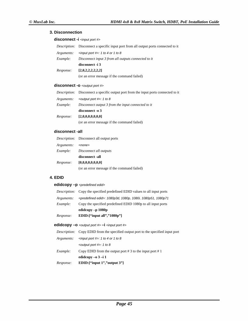
3. Disconnection
disconnect -i <input port #> Description: Disconnect a specific input port from all output ports connected to it
Arguments: <input port #>: 1 to 4 or 1 to 8
Example: Disconnect input 3 from all outputs connected to it disconnect -i 3 Response: [2,0,2,2,2,2,2,2] (or an error message if the command failed)
disconnect -o <output port #> Description: Disconnect a specific output port from the input ports connected to it
Arguments: <output port #>: 1 to 8
Example: Disconnect output 3 from the input connected to it disconnect -o 3 Response: [2,0,0,0,0,0,0,0] (or an error message if the command failed)
disconnect -all Description: Disconnect all output ports
Arguments: <none>
Example: Disconnect all outputs disconnect -all Response: [0,0,0,0,0,0,0,0] (or an error message if the command failed)
4. EDID
edidcopy –p <predefined edid> Description: Copy the specified predefined EDID values to all input ports
Arguments: <predefined edid>: 1080p3d, 1080p, 1080i, 1080p51, 1080p71
Example: Copy the specified predefined EDID 1080p to all input ports edidcopy –p 1080p
Response: EDID:[“input all”,”1080p”]
edidcopy –o <output port #> –i <input port #> Description: Copy EDID from the specified output port to the specified input port
Arguments: <input port #>: 1 to 4 or 1 to 8
<output port #>: 1 to 8
Example: Copy EDID from the output port # 3 to the input port # 1 edidcopy –o 3 –i 1
Response: EDID:[“input 1”,”output 3”]
Page 45
© MuxLab Inc. HDMI 4x8 & 8x8 Matrix Switch, HDBT, PoE Installation Guide
4. EDID (Continued)
edidcopy –o <output port #> Description: Copy EDID from the specified output port to all input ports
Arguments: <output port #>: 1 to 8
Example: Copy EDID from the output port # 2 to all input ports edidcopy –o 2
Response: EDID:[“input all”,”output 2”]
5. Get
get -i <input port #> Description: Get the connection state of a specific input port
Arguments: <input port #>: 1 to 4 or 1 to 8
Example: Get connection state of input port 2 get -i 2 Response: Input 02 connected to: 01 (or an error message if the command failed)
get -i Description: Get the connection state of all input ports
Arguments: <none>
Example: Get connection state of all input ports get -i Response: Input 01 connected to: none Input 02 connected to: 01 Input 03 connected to: none …{and so on} (or an error message if the command failed)
get -json Description: Get all the output connection states in json format
Arguments: <none>
Example: Get all output connections states in json format. get -json Response: [3,7,0,0,0,0,0,0] (or an error message if the command failed)
get -o <output port #> Description: Get the connection state of a specific output port
Arguments: <output port #>: 1 to 8
Example: Get connection state of output port 4 get -o 4 Response: Output 04 connected to: 1 (or an error message if the command failed)
Page 46
© MuxLab Inc. HDMI 4x8 & 8x8 Matrix Switch, HDBT, PoE Installation Guide
5. Get (Continued)
get -o Description: Get the connection state of all output ports
Arguments: <none>
Example: Get connection state of all output ports get -o Response: Output 01 connected to: 03 Output 02 connected to: 04 Output 03 connected to: none …{and so on} (or an error message if the command failed)
6. Help
help or ? Description: Display all the command list definition available
Arguments: <none>
Example: Display all the command list help ? Response: connect
connect –i <input port #> -o <output port #> {Connect 1 input port to 1 output port}
connect -i <input port #> -o all {Connect 1 input port to all output port}
connect -i <input port #> -o <from output port #>..<to output port #> {Connect 1 input port to a specific range of output port}
disconnect disconnect -i <input port #> {Disconnect 1 input port}
disconnect -o <output port #> {Disconnect 1 output port}
disconnect -all {Disconnect all input/output port}
… {and so on}
version version <no parameters> {Get the current firmware version}
Page 47
© MuxLab Inc. HDMI 4x8 & 8x8 Matrix Switch, HDBT, PoE Installation Guide
7. Name
name -i <input port #> “<name>”
Description: Set a name for the selected input port
Arguments: <input port #>: 1 to 4 or 1 to 8 <name>: up to 20 characters
Example: Set name “My DVD Player” for input port 4 name -i 4 “My DVD Player” Response: Input Names:[“Input 1”,”Input 2”,”Input 3”,“My DVD Player”…] (or an error message if the command failed)
name -i Description: Get a list of all the input port names
Arguments: <none>
Example: Get list of all input port names name -i Response: Input Names:[“Input 1”,”Input 2”,”Input 3”,“My DVD Player”…] (or an error message if the command failed)
name -o <output port #> “<name>” Description: Set a name for the selected output port
Arguments: <output port #>: 1 to 8 <name>: up to 20 characters
Example: Set the name “Kitchen TV” for output port 4 name -o 4 “Kitchen TV” Response: Output Names:[“Output 1”,“Output 2”,“Output 3”,“Kitchen TV” ”,“Output 5”,
“Output 6”,“Output 7”,“Output 8”] (or an error message if the command failed)
name -o Description: Get a list of all the output port names
Arguments: <none>
Example: Get list of all output port names name -o Response: Output Names:[“Output 1”,“Output 2”,“Output 3”,“Kitchen TV” ”,“Output 5”,
“Output 6”,“Output 7”,“Output 8”] (or an error message if the command failed)
name -preset <preset #> “<name>” Description: Set a name for the selected preset number
Arguments: <preset #>: 1 to 8 <name>: up to 20 characters
Example: Set name “Week-end” for preset 7 name -preset 7 “Week-end” Response: Preset Names:[“Preset 1”,“Preset 2”,“Preset 3”,“Preset 4”,“Preset 5”, “Preset 6”,“Week-end”,“Preset 8”] (or an error message if the command failed)
Page 48
© MuxLab Inc. HDMI 4x8 & 8x8 Matrix Switch, HDBT, PoE Installation Guide
7. Name (Continued)
name -preset Description: Get a list of all the preset names
Arguments: <none>
Example: Get list of all preset names name -preset Response: Preset Names:[“Preset 1”,“Preset 2”, “Preset 3”,“Preset 4”,“Preset 5”,
“Preset 6”,“Week-end”,“Preset 8”] (or an error message if the command failed)
name -unit “<name>” Description: Set a name for the unit
Arguments: <name>: up to 20 characters
Example: Set the name “MuxLab Switch” for the unit name -unit “MuxLab Switch” Response: Unit Name:[“MuxLab Switch”] (or an error message if the command failed)
name -unit Description: Get the unit name
Arguments: <none>
Example: Get the unit name name -unit Response: Unit Name:[“MuxLab Switch”] (or an error message if the command failed)
Page 49
© MuxLab Inc. HDMI 4x8 & 8x8 Matrix Switch, HDBT, PoE Installation Guide
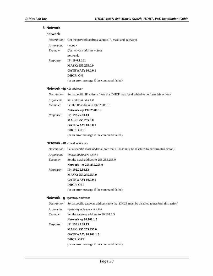
8. Network
network Description: Get the network address values (IP, mask and gateway)
Arguments: <none>
Example: Get network address values network Response: IP: 10.0.1.101 MASK: 255.255.0.0 GATEWAY: 10.0.0.1 DHCP: ON (or an error message if the command failed)
Network –ip <ip address> Description: Set a specific IP address (note that DHCP must be disabled to perform this action)
Arguments: <ip address>: #.#.#.#
Example: Set the IP address to 192.25.80.13 Network –ip 192.25.80.13 Response: IP: 192.25.80.13 MASK: 255.255.0.0 GATEWAY: 10.0.0.1 DHCP: OFF (or an error message if the command failed)
Network –m <mask address> Description: Set a specific mask address (note that DHCP must be disabled to perform this action)
Arguments: <mask address>: #.#.#.#
Example: Set the mask address to 255.255.255.0 Network –m 255.255.255.0 Response: IP: 192.25.80.13 MASK: 255.255.255.0 GATEWAY: 10.0.0.1 DHCP: OFF (or an error message if the command failed)
Network –g <gateway address> Description: Set a specific gateway address (note that DHCP must be disabled to perform this action)
Arguments: <gateway address>: #.#.#.#
Example: Set the gateway address to 10.101.1.5 Network –g 10.101.1.5 Response: IP: 192.25.80.13 MASK: 255.255.255.0 GATEWAY: 10.101.1.5 DHCP: OFF (or an error message if the command failed)
Page 50
© MuxLab Inc. HDMI 4x8 & 8x8 Matrix Switch, HDBT, PoE Installation Guide
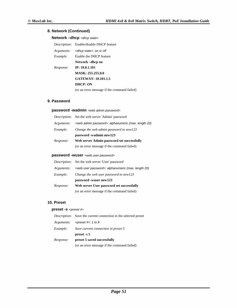
8. Network (Continued)
Network –dhcp <dhcp state> Description: Enable/disable DHCP feature
Arguments: <dhcp state>: on or off
Example: Enable the DHCP feature Network –dhcp on Response: IP: 10.0.1.101 MASK: 255.255.0.0 GATEWAY: 10.101.1.5 DHCP: ON (or an error message if the command failed)
9. Password
password -wadmin <web admin password> Description: Set the web server 'Admin' password
Arguments: <web admin password>: alphanumeric (max. length 20)
Example: Change the web admin password to new123 password -wadmin new123 Response: Web server Admin password set successfully (or an error message if the command failed)
password -wuser <web user password> Description: Set the web server 'User' password
Arguments: <web user password>: alphanumeric (max. length 20)
Example: Change the web user password to new123 password -wuser new123 Response: Web server User password set successfully (or an error message if the command failed)
10. Preset
preset -s <preset #> Description: Save the current connection in the selected preset
Arguments: <preset #>: 1 to 8
Example: Save current connection in preset 5 preset -s 5 Response: preset 5 saved successfully (or an error message if the command failed)
Page 51
© MuxLab Inc. HDMI 4x8 & 8x8 Matrix Switch, HDBT, PoE Installation Guide
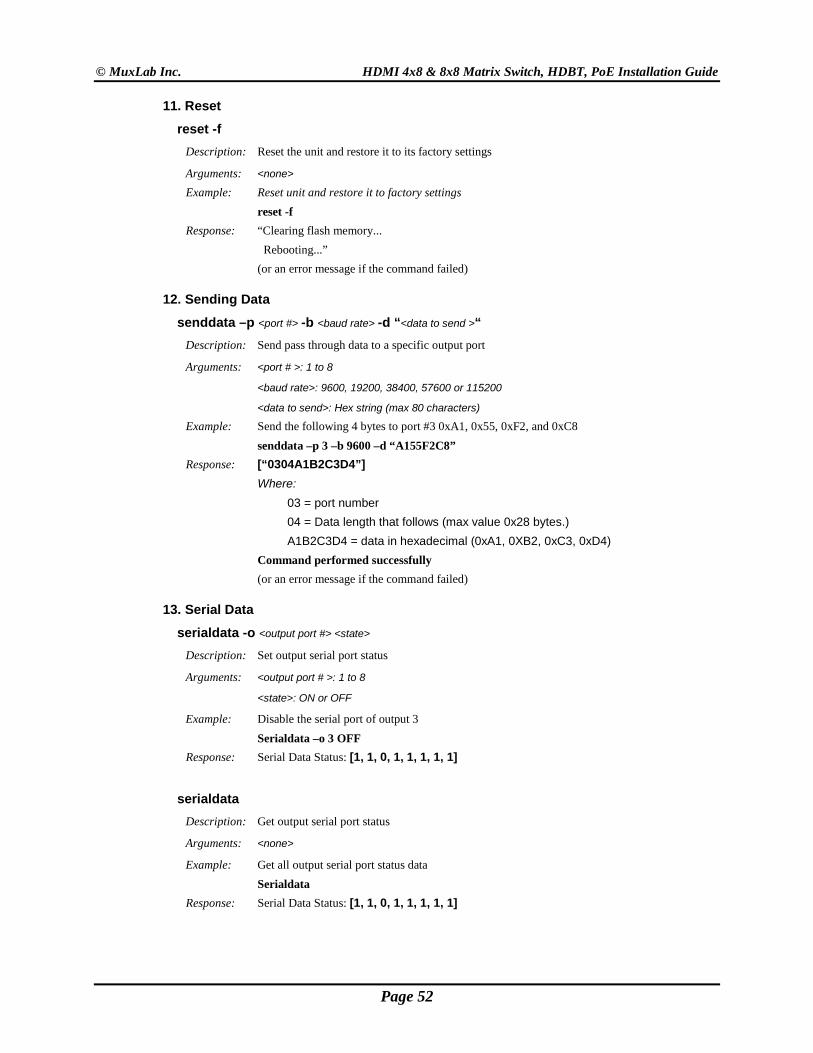
11. Reset
reset -f Description: Reset the unit and restore it to its factory settings
Arguments: <none>
Example: Reset unit and restore it to factory settings reset -f Response: “Clearing flash memory... Rebooting...” (or an error message if the command failed)
12. Sending Data
senddata –p <port #> -b <baud rate> -d “<data to send >“ Description: Send pass through data to a specific output port
Arguments: <port # >: 1 to 8
<baud rate>: 9600, 19200, 38400, 57600 or 115200
<data to send>: Hex string (max 80 characters)
Example: Send the following 4 bytes to port #3 0xA1, 0x55, 0xF2, and 0xC8 senddata –p 3 –b 9600 –d “A155F2C8”
Response: [“0304A1B2C3D4”] Where: 03 = port number 04 = Data length that follows (max value 0x28 bytes.) A1B2C3D4 = data in hexadecimal (0xA1, 0XB2, 0xC3, 0xD4)
Command performed successfully (or an error message if the command failed)
13. Serial Data
serialdata -o <output port #> <state> Description: Set output serial port status
Arguments: <output port # >: 1 to 8
<state>: ON or OFF
Example: Disable the serial port of output 3 Serialdata –o 3 OFF
Response: Serial Data Status: [1, 1, 0, 1, 1, 1, 1, 1]
serialdata Description: Get output serial port status
Arguments: <none>
Example: Get all output serial port status data Serialdata
Response: Serial Data Status: [1, 1, 0, 1, 1, 1, 1, 1]
Page 52
© MuxLab Inc. HDMI 4x8 & 8x8 Matrix Switch, HDBT, PoE Installation Guide
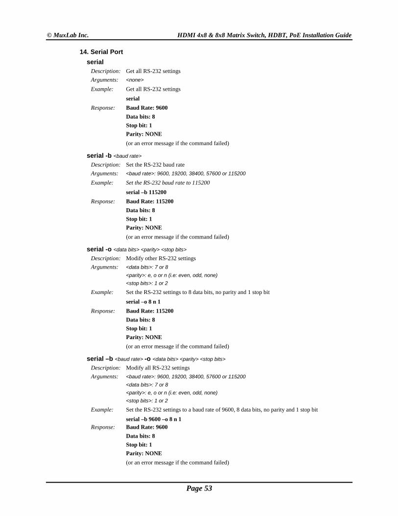
14. Serial Port serial
Description: Get all RS-232 settings Arguments: <none>
Example: Get all RS-232 settings serial
Response: Baud Rate: 9600 Data bits: 8 Stop bit: 1
Parity: NONE (or an error message if the command failed)
serial -b <baud rate> Description: Set the RS-232 baud rate Arguments: <baud rate>: 9600, 19200, 38400, 57600 or 115200
Example: Set the RS-232 baud rate to 115200 serial –b 115200
Response: Baud Rate: 115200 Data bits: 8 Stop bit: 1 Parity: NONE
(or an error message if the command failed)
serial -o <data bits> <parity> <stop bits> Description: Modify other RS-232 settings Arguments: <data bits>: 7 or 8 <parity>: e, o or n (i.e: even, odd, none) <stop bits>: 1 or 2
Example: Set the RS-232 settings to 8 data bits, no parity and 1 stop bit serial –o 8 n 1
Response: Baud Rate: 115200 Data bits: 8 Stop bit: 1 Parity: NONE
(or an error message if the command failed)
serial –b <baud rate> -o <data bits> <parity> <stop bits> Description: Modify all RS-232 settings Arguments: <baud rate>: 9600, 19200, 38400, 57600 or 115200 <data bits>: 7 or 8 <parity>: e, o or n (i.e: even, odd, none) <stop bits>: 1 or 2
Example: Set the RS-232 settings to a baud rate of 9600, 8 data bits, no parity and 1 stop bit serial –b 9600 –o 8 n 1
Response: Baud Rate: 9600 Data bits: 8 Stop bit: 1 Parity: NONE
(or an error message if the command failed)
Page 53
© MuxLab Inc. HDMI 4x8 & 8x8 Matrix Switch, HDBT, PoE Installation Guide
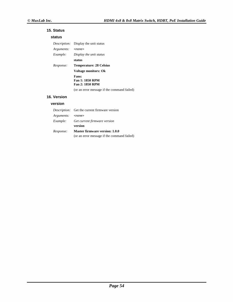
15. Status
status Description: Display the unit status Arguments: <none>
Example: Display the unit status status
Response: Temperature: 28 Celsius Voltage monitors: Ok
Fans: Fan 1: 1850 RPM Fan 2: 1850 RPM
(or an error message if the command failed)
16. Version
version Description: Get the current firmware version Arguments: <none>
Example: Get current firmware version version Response: Master firmware version: 1.0.0
(or an error message if the command failed)
Page 54
© MuxLab Inc. HDMI 4x8 & 8x8 Matrix Switch, HDBT, PoE Installation Guide
B. IP Control Commands 1. Notice This section is provided for informational purposes only, and should only be used by software developers with a thorough understanding of the HTTP and JSON specifications.
2. Introduction The Matrix Switch can be controlled using basic IP commands. These commands are based on the JSON format and are sent and received in standard TCP/IP packets. To learn more about JSON, visit http://www.json.org.
Only four types of JSON arrays are used to control the product: Array of a single integer: [2] Array of multiple integers: [1,2,3,4,5,6,7,8] Array of a single string: [“A Name”] Array of multiple strings: [“Name 1”, “Name 2”, “Name 3”, “Name 4”]
Any other notation is not permitted. Also, “null” values are not permitted. Use 0 instead.
3. Basic Usage All read and write operations are performed via HTTP GET and HTTP POST commands, respectively. While you can perform a GET at any time, a POST command will require prior authentication.
4. Basic Authentication
Authentication is performed in two simple steps:
1. Obtain a Session ID Perform a GET request on /var/session.json to obtain a new session ID. The return value will be a JSON array of a single integer, for example [12345]. From then on, simply append the session to any new IP requests to use this session, e.g., GET /var/conn.json?sid=12345
2. To Open a Session ID that will not expires
Perform a GET request on /var/xsession.json to obtain a session ID that will not expires. The return value will be a JSON array of a single integer, for example [12345]. From then on, simply append the session to any new IP requests to use this session, e.g., GET /var/conn.json?sid=12345
Page 55
© MuxLab Inc. HDMI 4x8 & 8x8 Matrix Switch, HDBT, PoE Installation Guide
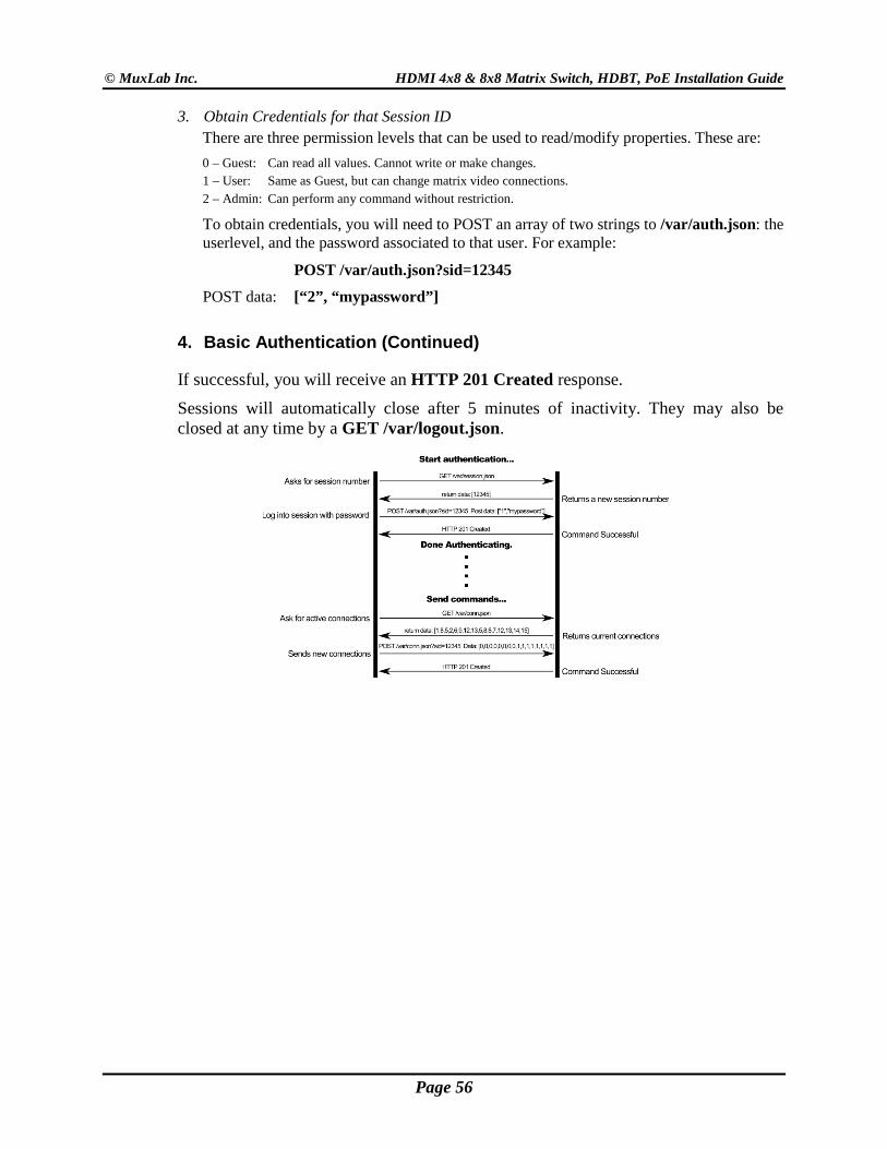
3. Obtain Credentials for that Session ID There are three permission levels that can be used to read/modify properties. These are: 0 – Guest: Can read all values. Cannot write or make changes. 1 – User: Same as Guest, but can change matrix video connections. 2 – Admin: Can perform any command without restriction.
To obtain credentials, you will need to POST an array of two strings to /var/auth.json: the userlevel, and the password associated to that user. For example:
POST /var/auth.json?sid=12345
POST data: [“2”, “mypassword”]
4. Basic Authentication (Continued)
If successful, you will receive an HTTP 201 Created response.
Sessions will automatically close after 5 minutes of inactivity. They may also be closed at any time by a GET /var/logout.json.
Page 56
© MuxLab Inc. HDMI 4x8 & 8x8 Matrix Switch, HDBT, PoE Installation Guide
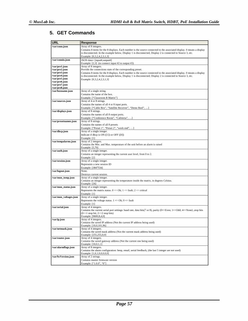
5. GET Commands
URL Response /var/conn.json Array of 8 integers.
Contains 8 items for the 8 displays. Each number is the source connected to the associated display. 0 means a display is disconnected. In the example below, Display 1 is disconnected, Display 2 is connected to Source 3, etc. Example: [0,3,2,4,2,3,1,3]
/var/connio.json JSON data= [input#,output#] Example: [2,3] (to connect input #2 to output #3)
/var/pre1.json /var/pre2.json /var/pre3.json /var/pre4.json /var/pre5.json /var/pre6.json /var/pre7.json /var/pre8.json
Array of 8 integers. Provide the connections state of the corresponding preset. Contains 8 items for the 8 displays. Each number is the source connected to the associated display. 0 means a display is disconnected. In the example below, Display 1 is disconnected; Display 2 is connected to Source 3, etc. Example: [0,3,2,4,2,3,1,3]
/var/boxname.json Array of a single string. Contains the name of the box. Example: [“Classroom B Matrix”]
/var/sources.json Array of 4 or 8 strings. Contains the names of all 4 or 8 input ports. Example: [“Cable Box”, “Satellite Receiver”, “Demo Reel”, …]
/var/displays.json Array of 8 strings. Contains the names of all 8 output ports. Example: [“Conference Room”, “Cafeteria”, …]
/var/presetnames.json Array of 8 strings. Contains the names of all 8 presets Example: [“Preset 1”, “Preset 2”, “week end”, …]
/var/dhcp.json Array of a single integer. Indicate if dhcp is ON ([1]) or OFF ([0]) Example: [1]
/var/tempalarms.json Array of 2 integers. Contains the Min. and Max. temperature of the unit before an alarm is raised Example: [5,70]
/var/auth.json Array of a single integer. Contains an integer representing the current user level, from 0 to 2. Example: [2]
/var/session.json Array of a single integer. Represents a new session ID Example: [3847534]
/var/logout.json None. Destroys current session.
/var/mon_temp.json Array of a single integer. Contains an integer representing the temperature inside the matrix, in degrees Celsius. Example: [26]
/var/mon_status.json Array of a single integer. Represents the matrix status. 0 => Ok; 1 => fault; 2 => critical Example: [1]
/var/mon_voltages.json Array of a single integer. Represents the voltage status. 1 => Ok; 0 => fault Example: [1]
/var/serial.json Array of 4 integers. Contains the current serial port settings: baud rate, data bits(7 or 8), parity (0=>Even; 1=>Odd; 4=>None) ,stop bits (0=>1 stop bit; 2=>2 stop bits) Example: [9600,8,4,0]
/var/ip.json Array of 4 integers. Contains the saved IP address (Not the current IP address being used) Example: [10,0,101,96]
/var/netmask.json Array of 4 integers. Contains the saved mask address (Not the current mask address being used) Example: [255,255,0,0]
/var/router.json Array of 4 integers. Contains the saved gateway address (Not the current one being used) Example: [10,0,1,1]
/var/alarmflags.json Array of 8 integers. Contains the alarm configuration: beep, email, serial feedback, (the last 5 integer are not used) Example: [1,0,1,0,0,0,0,0]
/var/fwVersion.json Array of 2 strings. Contains master firmware version Example: [“1.0.0”, “0”]
Page 57
© MuxLab Inc. HDMI 4x8 & 8x8 Matrix Switch, HDBT, PoE Installation Guide
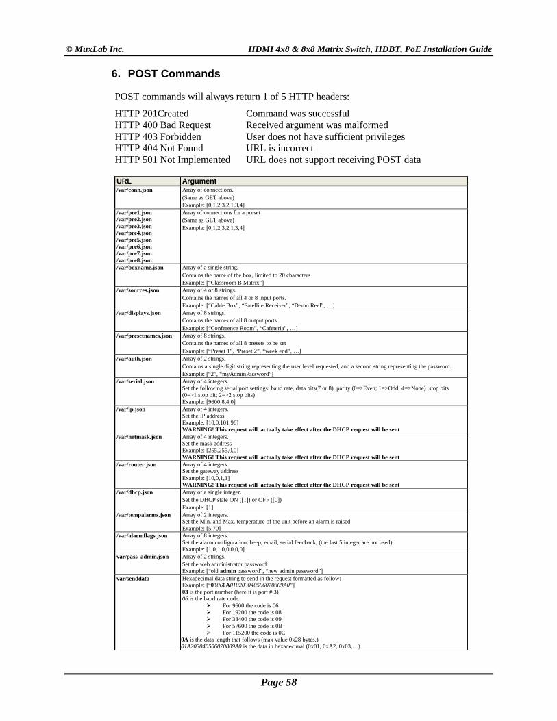
6. POST Commands
POST commands will always return 1 of 5 HTTP headers:
HTTP 201Created Command was successful HTTP 400 Bad Request Received argument was malformed HTTP 403 Forbidden User does not have sufficient privileges HTTP 404 Not Found URL is incorrect HTTP 501 Not Implemented URL does not support receiving POST data
URL Argument /var/conn.json Array of connections.
(Same as GET above) Example: [0,1,2,3,2,1,3,4]
/var/pre1.json /var/pre2.json /var/pre3.json /var/pre4.json /var/pre5.json /var/pre6.json /var/pre7.json /var/pre8.json
Array of connections for a preset (Same as GET above) Example: [0,1,2,3,2,1,3,4]
/var/boxname.json Array of a single string. Contains the name of the box, limited to 20 characters Example: [“Classroom B Matrix”]
/var/sources.json Array of 4 or 8 strings. Contains the names of all 4 or 8 input ports. Example: [“Cable Box”, “Satellite Receiver”, “Demo Reel”, …]
/var/displays.json Array of 8 strings. Contains the names of all 8 output ports. Example: [“Conference Room”, “Cafeteria”, …]
/var/presetnames.json Array of 8 strings. Contains the names of all 8 presets to be set Example: [“Preset 1”, “Preset 2”, “week end”, …]
/var/auth.json Array of 2 strings. Contains a single digit string representing the user level requested, and a second string representing the password. Example: [“2”, “myAdminPassword”]
/var/serial.json Array of 4 integers. Set the following serial port settings: baud rate, data bits(7 or 8), parity (0=>Even; 1=>Odd; 4=>None) ,stop bits (0=>1 stop bit; 2=>2 stop bits) Example: [9600,8,4,0]
/var/ip.json Array of 4 integers. Set the IP address Example: [10,0,101,96] WARNING! This request will actually take effect after the DHCP request will be sent
/var/netmask.json Array of 4 integers. Set the mask address Example: [255,255,0,0] WARNING! This request will actually take effect after the DHCP request will be sent
/var/router.json Array of 4 integers. Set the gateway address Example: [10,0,1,1] WARNING! This request will actually take effect after the DHCP request will be sent
/var/dhcp.json Array of a single integer. Set the DHCP state ON ([1]) or OFF ([0]) Example: [1]
/var/tempalarms.json Array of 2 integers. Set the Min. and Max. temperature of the unit before an alarm is raised Example: [5,70]
/var/alarmflags.json Array of 8 integers. Set the alarm configuration: beep, email, serial feedback, (the last 5 integer are not used) Example: [1,0,1,0,0,0,0,0]
var/pass_admin.json Array of 2 strings. Set the web administrator password Example: [“old admin password”, “new admin password”]
var/senddata Hexadecimal data string to send in the request formatted as follow: Example: [“03060A010203040506070809A0”] 03 is the port number (here it is port # 3) 06 is the baud rate code:
For 9600 the code is 06 For 19200 the code is 08 For 38400 the code is 09 For 57600 the code is 0B For 115200 the code is 0C
0A is the data length that follows (max value 0x28 bytes.) 01A203040506070809A0 is the data in hexadecimal (0x01, 0xA2, 0x03,…)
Page 58
© MuxLab Inc. HDMI 4x8 & 8x8 Matrix Switch, HDBT, PoE Installation Guide
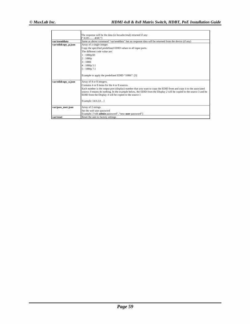
The response will be the data (in hexadecimal) returned if any: [“A105……450C”]
var/xsenddata Same as above command “var/senddata” but no response data will be returned from the device (if any) var/edidcopy_p.json Array of a single integer.
Copy the specified predefined EDID values to all input ports. The different code value are: 1 : 1080p3D 2 : 1080p 3 : 1080i 4 : 1080p 5.1 5 : 1080p 7.1 Example to apply the predefined EDID “1080i”: [3]
var/edidcopy_o.json Array of 4 or 8 integers. Contains 4 or 8 items for the 4 or 8 sources. Each number is the output port (display) number that you want to copy the EDID from and copy it to the associated source. 0 means do nothing. In the example below, the EDID from the Display 2 will be copied to the source 3 and he EDID from the Display 4 will be copied to the source 1 Example: [4,0,2,0…]
var/pass_user.json Array of 2 strings. Set the web user password Example: [“old admin password”, “new user password”]
var/reset Reset the unit to factory settings
Page 59
© MuxLab Inc. HDMI 4x8 & 8x8 Matrix Switch, HDBT, PoE Installation Guide
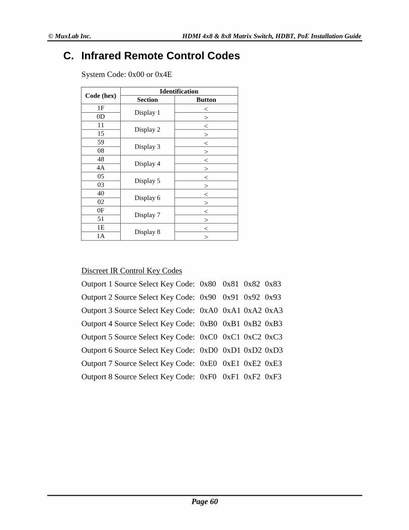
C. Infrared Remote Control Codes System Code: 0x00 or 0x4E
Code (hex) Identification Section Button
1F Display 1 <
0D > 11
Display 2 < 15 > 59
Display 3 < 08 > 48
Display 4 < 4A > 05
Display 5 < 03 > 40
Display 6 < 02 > 0F
Display 7 < 51 > 1E
Display 8 < 1A >
Discreet IR Control Key Codes
Outport 1 Source Select Key Code: 0x80 0x81 0x82 0x83
Outport 2 Source Select Key Code: 0x90 0x91 0x92 0x93
Outport 3 Source Select Key Code: 0xA0 0xA1 0xA2 0xA3
Outport 4 Source Select Key Code: 0xB0 0xB1 0xB2 0xB3
Outport 5 Source Select Key Code: 0xC0 0xC1 0xC2 0xC3
Outport 6 Source Select Key Code: 0xD0 0xD1 0xD2 0xD3
Outport 7 Source Select Key Code: 0xE0 0xE1 0xE2 0xE3
Outport 8 Source Select Key Code: 0xF0 0xF1 0xF2 0xF3
Page 60
© MuxLab Inc. HDMI 4x8 & 8x8 Matrix Switch, HDBT, PoE Installation Guide
6. Product Warranty Policy
Items Under Warranty - Company Policy MuxLab guarantees its products to be free of defects in manufacturing and workmanship for the warranty period from the date of purchase. If this product fails to give satisfactory performance during this warranty period, MuxLab will either repair or replace this product at no additional charge, except as set forth below. Repair and replacement parts will be furnished on an exchange basis and will be either reconditioned or new. All replaced parts and products become the property of MuxLab. This limited warranty does not include repair services for damage to the product resulting from accident, disaster, misuse, abuse, or unauthorized modifications or normal decay of battery driven devices. Batteries, if included with the product, are not covered under this warranty.
Limited warranty service can be obtained by delivering the product during the warranty period to the authorized MuxLab dealer from whom you purchased the product, or by sending it to MuxLab. MuxLab will not accept any such product for repair without a Return Material Authorization number (RMA#) issued by its Customer Service Department and a proof of purchase date. If this product is delivered to MuxLab by mail, you agree to assume risk of loss or damage in transit, to prepay shipping charges to the warranty service location, and to use the original shipping container or equivalent.
THE ABOVE LIMITED WARRANTY IS THE ONLY WARRANTY COVERING YOUR MUXLAB PRODUCT. THERE ARE NO OTHER WARRANTIES, EXPRESSED OR IMPLIED, INCLUDING WARRANTIES OF MERCHANTABILITY OR FITNESS FOR A PARTICULAR PURPOSE. SOME STATES DO NOT ALLOW LIMITATIONS ON IMPLIED WARRANTIES, SO THE ABOVE LIMITATION MAY NOT APPLY TO YOU.
IF THIS PRODUCT IS NOT IN GOOD WORKING ORDER, YOUR SOLE REMEDY SHALL BE REPAIR OR REPLACEMENT AS PROVIDED FOR ABOVE. IN NO EVENT SHALL MuxLab BE LIABLE TO YOU FOR ANY DAMAGES, INCLUDING ANY LOSS OF PROFITS, LOST SAVINGS, OR OTHER INCIDENTAL OR CONSEQUENTIAL DAMAGES ARISING OUT OF THE USE OF OR INABILITY TO USE THIS PRODUCT, EVEN IF MUXLAB OR AN AUTHORIZED MuxLab DEALER HAS BEEN ADVISED OF THE POSSIBILITY OF SUCH DAMAGES; NOR WILL MUXLAB BE LIABLE FOR ANY CLAIM BY ANY OTHER PARTY. SOME STATES DO NOT ALLOW THE EXCLUSION OR LIMITATION OF INCIDENTAL OR CONSEQUENTIAL DAMAGES FOR CONSUMER PRODUCTS, SO THE ABOVE LIMITATIONS OR EXCLUSIONS MAY NOT APPLY TO YOU. THIS WARRANTY GIVES YOU SPECIFIC LEGAL RIGHTS. YOU MAY ALSO HAVE OTHER RIGHTS WHICH MAY VARY FROM STATE TO STATE.
Page 61

© MuxLab Inc. HDMI 4x8 & 8x8 Matrix Switch, HDBT, PoE Installation Guide
Warranty Periods Any product found to be defective within three (3) months of invoice, including one (1) month shelf life, may be returned for replacement by a new unit or a satisfactory repair within one (1) month of receiving any returned product. The customer must provide MuxLab with the serial number and proof of purchase of the defective unit being returned. All R.M.A.’s issued are subject to inspection by MuxLab, and will be returned to customer if not properly package – units must be returned in original container or equivalent. MuxLab will not accept any such product for repair without an authorization for its Technical Support department and without a return authorization number issued by MuxLab Customer Service department. For credit & replace R.M.A., customer will be liable to pay replacement invoice if defective products are not returned. Product more than six months old, including shelf life. The defective unit must be returned prepaid to MuxLab and then the unit will be repaired or if repair is not possible, replaced by an equivalent unit and returned to the customer within one (1) month of receiving any returned product. There is no charge for repair (parts and labor) during the full warranty period. Items Defective and not under Warranty For products which are no longer under warranty the policy is repair and return. An amount of 25% of the products published list price at the time of purchase will be charged. Customer must issue a purchase order to cover the cost of repair. Each unit will be returned to the customer within one (1) month from receipt of the unit by MuxLab. The defective unit must be returned prepaid to MuxLab. The repaired unit will be returned to the customer FOB MuxLab. The repaired unit has a 90 day warranty.
MuxLab Inc. 8495 Dalton Road
Mount Royal, Quebec Canada H4T 1V5
Tel.: +1 (514) 905-0588 Fax: +1 (514) 905-0589 Toll Free (North America): 877 689-5228
URL: www.muxlab.com E-mail: [email protected]
Page 62