HD Data Logger User Manual
23
HD Data Logger User Manual © 2020 DG Technologies Document 1.01 Document Date: May 2021 DG Technologies 33604 West Eight Mile Road Farmington Hills, MI 48335 Phone (248) 888-2000 Fax (248) 888-9977
Transcript of HD Data Logger User Manual

HD Data Logger User Manual
© 2020 DG Technologies
Document 1.01
Document Date: May 2021
DG Technologies 33604 West Eight Mile Road Farmington Hills, MI 48335 Phone (248) 888-2000 Fax (248) 888-9977

2
This document describes the DG HD Data Logger. The HD Data Logger collects digital message
data from a vehicle network for various types of analysis, such as vehicle performance, cost
efficiency, problem diagnosis or network development work.
The DG HD Data Logger provides a complete picture of what is happening in the vehicle for
analysis or diagnosis of the user’s specific concerns.
Permission is granted to copy any or all portions of this manual, provided that such copies are for
use with the DG HD Data Logger product and that “© 2020 DG Technologies.”, (herein referred
to as “Dearborn Group”, “DG Technologies”, or “DG”), remains on all copies.
The accompanying software, provided for use with the DG HD Data Logger, is also copyrighted.
Permission is granted to copy this software for back-up purposes only.
I M P O R T A N T
To ensure your success with this product, it is essential that you read this document carefully
before using the hardware.
Damage caused by misuse of the hardware is not covered under product warranty. When using
this manual, please remember the following:
• This manual may be changed, in whole or in part, without notice.
• DG assumes no responsibility for any damage resulting from the use of this
hardware or software.
• Specifications presented herein are provided for illustration purposes only and
may not accurately represent the latest revisions of hardware, software or cabling.
• No license is granted, by implication or otherwise, for any patents or other rights
of DG or of any third party.
DG® logo is a registered trademark of DG Technologies, Inc. Other products that may be
referenced in this manual are trademarks of their respective manufacturers.
© 2020 DG Technologies

3
Introduction ............................................................................................... 5
Data Logger Overview .............................................................................. 7
Power ........................................................................................................................................................ 7
Hardware Interfaces ................................................................................................................................. 7
Trigger Modes ........................................................................................................................................... 7
Operational Sequence............................................................................................................................... 7
Start Logging Conditions ........................................................................................................................... 9
Trigger Mode:............................................................................................................................................ 9
Manual Trigger Mode ........................................................................................................................... 9
Stop Logging Triggers ................................................................................................................................ 9
Automatic Mode ................................................................................................................................... 9
Manual Mode ........................................................................................................................................ 9
Data Logging............................................................................................................................................ 10
Log Data File: ....................................................................................................................................... 10
Log Data File Name: ............................................................................................................................ 10
Start [StartDate]-[StartTime]_End [EndDate]-[EndTime] ................................................................... 10
Set-Up – Loading Instructions ............................................................... 11
Data Logger Operation ........................................................................... 12
USB Thumb Drive .................................................................................................................................... 12
User Interface ......................................................................................................................................... 12
Display ................................................................................................................................................. 12
Data Logger Settings ............................................................................................................................... 13
Edit the Configuration File on a PC - INI File ....................................................................................... 14
USB Thumb Drive Operation ................................................................................................................... 15
For Data Logger Operation with a USB Thumb Drive ......................................................................... 16
For Data Logger Operation Without a USB Thumb Drive ................................................................... 16
The Display .......................................................................................................................................... 16
After Data Logging is Completed ........................................................................................................ 16
Configuration parameters in INI file ....................................................................................................... 17
Optional HD DL Kit .............................................................................................................................. 18
Beacon Manual ................................................................................................................................... 18

4
Technical Support and Return Merchandise Authorization ................ 19
Return Merchandise Authorization (RMA)........................................................................................ 20
Appendix A. Warranty Information and Limitation Statements ......... 21
Warranty Information ........................................................................................................................... 21
Limitation Statements .......................................................................................................................... 21
General Limitation and Risk Assignment ...................................................................................... 21
Exclusion of Incidental, Consequential and Certain Other Damages ...................................... 22
Limitation of Liability and Remedies .............................................................................................. 22
Right to Revise or Update Without Notice .................................................................................... 22
Governance ....................................................................................................................................... 22
Contact ............................................................................................................................................... 22
Appendix B - List of Acronyms Used in this Document ...................... 23
5
Introduction
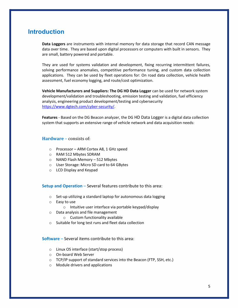
Data Loggers are instruments with internal memory for data storage that record CAN message data over time. They are based upon digital processors or computers with built in sensors. They are small, battery powered and portable.
They are used for systems validation and development, fixing recurring intermittent failures, solving performance anomalies, competitive performance tuning, and custom data collection applications. They can be used by fleet operations for: On road data collection, vehicle health assessment, fuel economy logging, and route/cost optimization.
Vehicle Manufacturers and Suppliers: The DG HD Data Logger can be used for network system development/validation and troubleshooting, emission testing and validation, fuel efficiency analysis, engineering product development/testing and cybersecurity https://www.dgtech.com/cyber-security/.
Features - Based on the DG Beacon analyzer, the DG HD Data Logger is a digital data collection system that supports an extensive range of vehicle network and data acquisition needs:
Hardware – consists of:
o Processor – ARM Cortex A8, 1 GHz speed o RAM 512 Mbytes SDRAM o NAND Flash Memory – 512 Mbytes o User Storage: Micro SD card to 64 GBytes o LCD Display and Keypad
Setup and Operation – Several features contribute to this area:
o Set-up utilizing a standard laptop for autonomous data logging o Easy to use
o Intuitive user interface via portable keypad/display o Data analysis and file management
o Custom functionality available o Suitable for long test runs and fleet data collection
Software – Several items contribute to this area:
o Linux OS interface (start/stop process) o On-board Web Server o TCP/IP support of standard services into the Beacon (FTP, SSH, etc.) o Module drivers and applications

6
Benefits – There are several contributions for your business by using this system:
o Suited for laboratory and vehicle applications o Import/Export data management o Remote control capability for set-up and operation o Report generation o Data Logger operates in “passive” mode not effecting the CAN network o Raw CAN data recorded on all networks o Logged Data File named in a standard format o Data logging can be fully operational without a keypad/display connected o High volume data collection for engineering development o All logged data files can automatically be transferred to:
o Internal memory o Memory stick o Offloaded wirelessly to a network
o Real time Data Display o Data Storage, at end of run o Automated Cloud Data Storage allows access via internet
Use Case – examples:
o On-road/Off-road Data Logging o Automated repetitive testing across multiple installations/laboratories o Remote test execution and data collection o Fleet data collection o Fleet application, with analytics o EOL test system o Vehicle emissions testing
Technical Aspects– examples:
o ECU communications o RAW CAN Data o Emission sensor signals o Auto-baud detect on all channels at power-up o Automatic or manual start and stop o Start/stop on triggers (automated) o Data file can be saved on internal SD card or external device o Data can be saved in a binary format o Application to convert to ASC format is available for offline playback

7
Data Logger Overview
Power o Power to the Beacon is provided from vehicle via the diagnostic link connector.
o Tool is ready to begin data acquisition within a user configurable number of seconds of vehicle
ignition ON.
Hardware Interfaces The following interfaces are supported: Connection to vehicle via green J1939 type-2 9-pin diagnostic
connector (backward compatible with black 9-pin connector from older vehicles) and 16 PIN OBD
connector.
o CAN – maximum 3 channels
o LCD display/keypad
The datalogger operates in “passive” mode, so as not to influence the CAN network. The datalogger:
o Will not send any messages, including responses and address claims.
o No additional termination is required for operation.
o Specified Baud Rate set in INI file.
Trigger Modes o Auto Trigger is capable of logging in Automatic (display NOT required) or Manual mode, PGN per
user input as specified by Triggers in INI File.
o If a keypad is not present, the Data Logger will operate in Automatic mode. Triggers need to be
specified in the INI file to run in automatic mode.
Operational Sequence o The Data logger operation is displayed in the following Flow Chart:

8
HD Data Logger Application
9
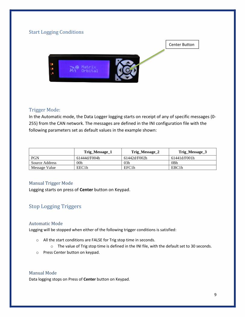
Start Logging Conditions
Trigger Mode:
In the Automatic mode, the Data Logger logging starts on receipt of any of specific messages (0-
255) from the CAN network. The messages are defined in the INI configuration file with the
following parameters set as default values in the example shown:
Trig_Message_1 Trig_Message_2 Trig_Message_3
PGN 61444d/F004h 61442d/F002h 61441d/F001h
Source Address 00h 03h 0Bh
Message Value EEC1h EFC1h EBC1h
Manual Trigger Mode
Logging starts on press of Center button on Keypad.
Stop Logging Triggers
Automatic Mode
Logging will be stopped when either of the following trigger conditions is satisfied:
o All the start conditions are FALSE for Trig stop time in seconds.
o The value of Trig stop time is defined in the INI file, with the default set to 30 seconds.
o Press Center button on keypad.
Manual Mode
Data logging stops on Press of Center button on Keypad.
Center Button

10
Data Logging
CAN data is recorded on all specified channels (RAW CAN as specified in INI file):
o Pins CD (CAN1)
o FG (CAN2)
o HJ (CAN3)
Data will be logged in a binary data file format during the drive cycle: o One file will be generated for each start-stop sequence. o The data file will be closed when logging is stopped.
Log Data File:
o The logged data is saved on the internal SD card.
o Maximum data file can be changed in the INI File.
o If the file exceeds the INI File Maximum Size, it will be closed and a new data file will be started.
Log Data File Name:
The data file is named as
o Start
o [StartDate]
o [StartTime]
o End
o [EndDate]
o [EndTime]
Start [StartDate]-[StartTime]_End [EndDate]-[EndTime]
o StartDate, EndDate in MMDDYY Format. o StartTime, EndTime in HHMMSS, 24 Hour Format.
o Example: Start080520-144511_End080520-144856.asc
11
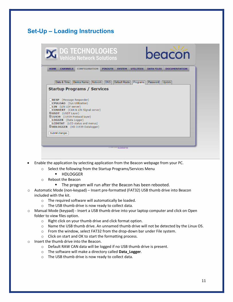
Set-Up – Loading Instructions
• Enable the application by selecting application from the Beacon webpage from your PC.
o Select the following from the Startup Programs/Services Menu
▪ HDLOGGER o Reboot the Beacon
▪ The program will run after the Beacon has been rebooted. o Automatic Mode (non-keypad) – Insert pre-formatted (FAT32) USB thumb drive into Beacon
included with the kit. o The required software will automatically be loaded. o The USB thumb drive is now ready to collect data.
o Manual Mode (keypad) - Insert a USB thumb drive into your laptop computer and click on Open folder to view files option.
o Right click on your thumb drive and click format option. o Name the USB thumb drive. An unnamed thumb drive will not be detected by the Linux OS. o From the window, select FAT32 from the drop-down bar under File system. o Click on start and OK to start the formatting process.
o Insert the thumb drive into the Beacon. o Default RAW CAN data will be logged if no USB thumb drive is present. o The software will make a directory called Data_Logger. o The USB thumb drive is now ready to collect data.
12
Data Logger Operation
USB Thumb Drive
After USB (FAT 32) thumb drive installation for both Automatic and Manual Modes
o Connect to the Data Logger device in the truck to the Diagnostic Link Connector (Deutsch connector etc.).
o Ignition ON ▪ Data logger functions in the background when the truck is running based
upon configuration as defined in the INI file (for detailed information refer to https://www.dgtech.com/documents/).
▪ Data acquisition occurs when START conditions are satisfied. ▪ Data is saved on the Beacon’s internal SD-card. ▪ Data files are converted and transferred from binary to ASC and transferred
to the internal SD-card to the USB thumb drive. ▪ Data acquisition stops per defined STOP conditions (MB limits defined in INI
File. o The Display shows the status of the Data Acquisition (messages, LEDs).
▪ There can be multiple drive cycles before removing the USB thumb drive. ▪ The USB thumb drive contains all the collected data. ▪ Once the display states “Copy Done” it is safe to remove the USB thumb
drive from the Beacon. o If a USB thumb drive is plugged in after the logging operation has begun:
o Device will sense that a USB thumb drive is inserted into the drive.
o The log files on present on the SD-card will be converted to the .ASC format and
written to the USB thumb drive.
o LED status lights indicate file transfer activity.
o If the USB thumb drive is full while data is being transferred, the oldest file on
the thumb drive will be deleted.
User Interface
Keypad: the center button is used as follows:
o Automatic mode: Stop a current data logging session.
o Manual mode: Start/Stop data logging
Display
The messages on the Display are noted on the Flow Chart and the LED’s are noted on the Flow
Chart and represented below:

13
Num Message LED State
1 Press ENTER within Trig_man_time seconds to go to Manual Mode GREEN
2 Waiting for Auto Trigger GREEN
3 Waiting for Manual Trigger. Press ENTER to Start logging GREEN
4 Auto Logging in Progress. Press ENTER to Stop Logging YELLOW
5 Manual Logging in Progress. Press ENTER to Stop Logging YELLOW
6 Logging Stopped YELLOW
7 Transfer to USB Stick – Safe to remove stick GREEN
When logging is terminated and a log file is closed on the internal SD card, if a USB thumb drive
is present:
o The log file is converted to a .ASC file.
o The .ASC file is written to the USB thumb drive.
Datalogger Settings
Determine the required data logger settings (the various parameters are described below) o Various settings include;
o Data collection mode: o Automatic – presence of a trigger
▪ Automatic data collection ▪ Auto trigger cannot stop manually
o Manual – selected by the keypad ▪ Will not stop collecting data unless push center button
o Automatic with Manual Override o Start Conditions:
o Set Trigger ▪ Based upon 1 to 255 messages defined by PGN ▪ Message value/SA (example PGN1=OxF001)
o Stop Conditions: o Set Stop Condition
▪ Trigger Stop Time (example=30 // in seconds o Baud Rates:
o Select on each of the channels
14
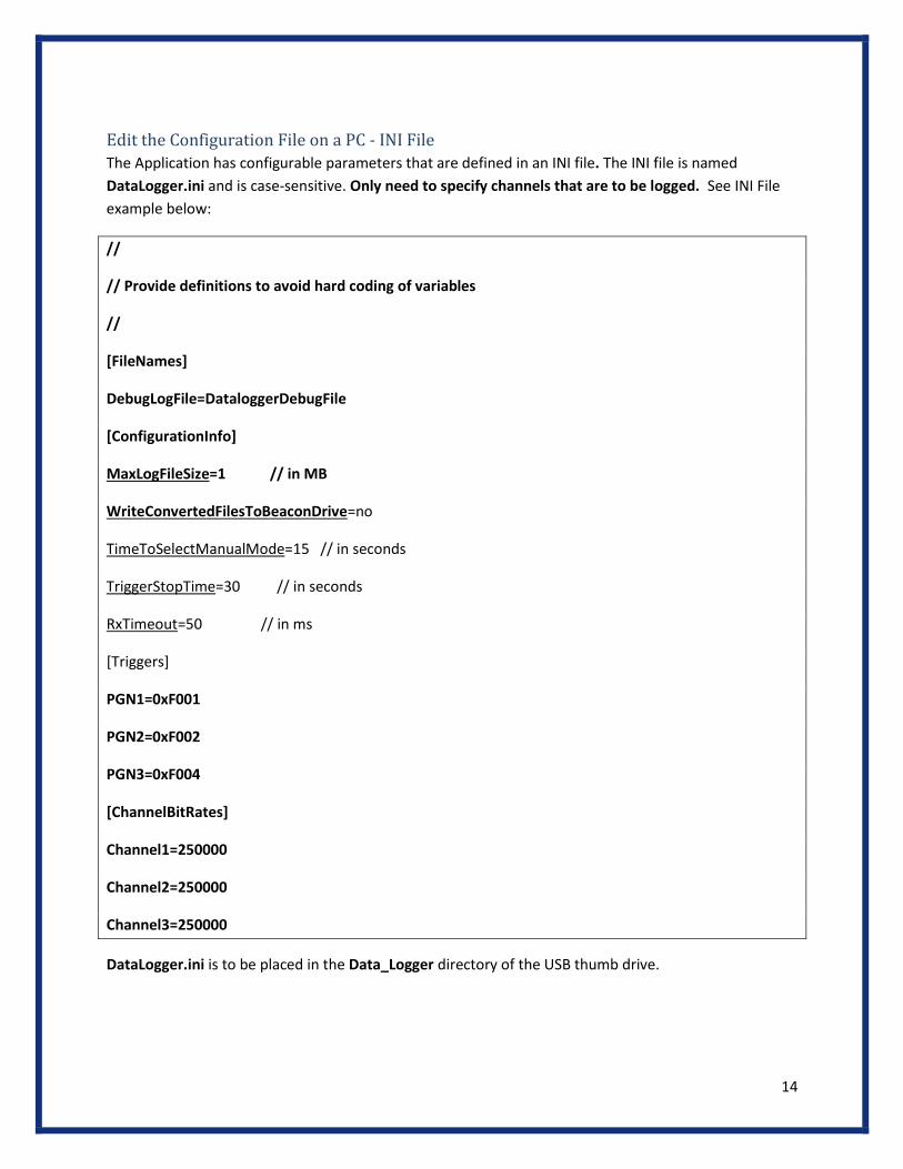
Edit the Configuration File on a PC - INI File
The Application has configurable parameters that are defined in an INI file. The INI file is named
DataLogger.ini and is case-sensitive. Only need to specify channels that are to be logged. See INI File
example below:
//
// Provide definitions to avoid hard coding of variables
//
[FileNames]
DebugLogFile=DataloggerDebugFile
[ConfigurationInfo]
MaxLogFileSize=1 // in MB
WriteConvertedFilesToBeaconDrive=no
TimeToSelectManualMode=15 // in seconds
TriggerStopTime=30 // in seconds
RxTimeout=50 // in ms
[Triggers]
PGN1=0xF001
PGN2=0xF002
PGN3=0xF004
[ChannelBitRates]
Channel1=250000
Channel2=250000
Channel3=250000
DataLogger.ini is to be placed in the Data_Logger directory of the USB thumb drive.

15
USB Thumb Drive Operation
At Power up, the application checks for the presence of a USB thumb drive in the USB drive and
reads the configuration file if present in the Data_Logger directory of the USB thumb drive.
If a USB thumb drive is present in the Data_Logger directory of the USB thumb drive:
o Any existing log files on the SD Card will be converted to a .ASC format and transferred
to the Data_Logger directory of the USB thumb drive
When logging is terminated and log file is closed on the internal SD card and a USB thumb drive
card is present:
o The log file is converted to a .ASC file.
o The .ASC file is written to the USB thumb drive
When logging is terminated and a log file is closed on the internal SD card, if a USB thumb drive
is present:
o The log file is converted to a .ASC file.
o The .ASC file is written to the USB thumb drive.
After configuration and the file has been written, the file will be deleted from the SD card:
o File conversion and copying is run in the background process.
o If a USB thumb drive is plugged in after the logging operation has begun:
o Device will sense that a USB thumb drive is inserted into the drive.
o The log files on present on the SD-card will be converted to the .ASC format and
written to the USB thumb drive.
o LED status lights indicate file transfer activity
o If the USB thumb drive is full while data is being transferred, the oldest file on
the thumb drive will be deleted.

16
For Data Logger Operation with a USB Thumb Drive
Load the configuration INI file on to the USB thumb drive
o Connect the USB thumb drive to the Beacon
o The data logger functions when the truck is running: o START/STOP conditions and other parameters are defined in the INI file. o Data acquisition occurs when manual/automatic START conditions are
satisfied. o Data is saved on the Beacon’s internal SD-card in binary format. o Data files are converted from binary to ASC and transferred from the SD-
card to the USB thumb drive. o Data acquisition stops per defined STOP conditions. o Some DL control functions are provided via the keypad.
o The Display shows the status of the Data Acquisition (messages, LEDs) and User prompts.
o Whenever a drive cycle is completed: o Logged data files on the Beacon’s SD Card are closed. o The data files are converted and transferred to the USB thumb drive (if
available) and can take 15-60 seconds to convert from binary to ASC based upon log file size.
o Multiple drive cycles are possible before removing the USB thumb drive.
For Data Logger Operation Without a USB Thumb Drive
Uses the INI file in the Beacon Directory
The Display
Prompts the user for real-time commands and provides the status of Data Acquisition by:
o Messages
o LED’s
After Data Logging is Completed
Multiple drive cycles are possible before removing the USB thumb drive.
o If a USB thumb drive is present
o Wait 10 seconds to allow conversion of data files before shutting off the engine
o The USB thumb drive has saved all the data files
▪ Can be safely removed at this time
o If a USB thumb drive is absent
o The engine can be turned off immediately
o All data files will be saved

17
Configuration parameters in INI file
3 Triggers for Automatic Data collection start. Default values shown below (can be changed by the user in the INI file as needed):
• //
• // Provide definitions to avoid hard coding of variables
• //
• [ConfigurationInfo]
• MaxLogFileSize=100 // in MB
• TimeToSelectManualMode=15 // in seconds
• TriggerStopTime=30 // in seconds
• RxTimeout=50 // in ms
• [ChannelBitRates]
• Channel1=250000
• //Channel2=250000
• //Channel3=250000
• [Triggers]
• PGN1=0xf00400
• PGN2=0xf00203
• PGN3=0xf0010b

18
Optional HD DL Kit
o Beacon
o LCD Display and Keypad (P/N ELK204-7T-USB-PL)
o 9 PIN Deutsch Cable (P/N DG-295-10811) *
o 16 PIN J1962 OBDII Cable (P/N 295-DGT-1000717) *
o USB thumb drive – 16GB or more
*Dependent on customer choice
Beacon Manual
For specific information on Beacon operation refer to Beacon Manual –
https://www.dgtech.com/wp-content/uploads/2018/01/Beacon_User_Manual.pdf

19
Technical Support and Return Merchandise Authorization
After reading and following the troubleshooting and validation procedures in this
document please check the FAQ page at www.dgtech.com/faqs. If you are still
not able to resolve an issue, please feel free to contact DG technical support.
For users in the United States, technical support is available from 9 a.m. to 5
p.m. Eastern Time. You may also fax or e-mail your questions to us. For prompt
assistance, please include your voice telephone number and the serial number
located on the bottom of your HD (Beacon) Data Logger.
DG Technologies Technical Support
Phone: (248) 888-2000
Fax: (248) 888-9977
E-mail: [email protected]
Web site:www.dgtech.com/tech-support
Users not residing in the United States should contact your local DG
representative or e-mail [email protected]

20
Return Merchandise Authorization (RMA)
If technical support has deemed that there may be a physical problem with your
HD Data Logger, you will be issued you an RMA number. You would then return
the product along with any documentation of ownership you have (proof of
purchase/price) to the following address:
Product Repair Services
Attn: RMA# xxxxxxx
DG Technologies
33604 West 8 Mile Road
Farmington Hills, MI 48335

21
Appendix A. Warranty Information and Limitation Statements
Warranty Information
DG Technologies, Inc. the HD Data Logger is warranted against defects in
materials and workmanship for two (2) years following date of shipment. Cables
(both USB and vehicle) are warranted for 90 days.
DG Technologies will, at its option, repair or replace, at no cost to the customer,
products which prove to be defective during the warranty period, provided the
defect or failure is not due to misuse, abuse, or alteration of the product. The
customer is responsible for shipment of the defective product to DG. This
warranty does not cover damage to any item that DG Technologies, determines
has been damaged by the customer's abuse, misuse, negligence, improper
assembly, modification, or operation of the product.
A Return Merchandise Authorization (RMA) number must be issued to the
customer by our Technical Support Department at (248) 888-2000 and must be
included with the product being returned (for more details, see section Return
Merchandise Authorization (RMA)). The HD Data Logger is warranted for 90
days after a warranty repair, or to end of the original factory warranty period,
whichever is longer.
Limitation Statements
General Limitation and Risk Assignment
To the maximum extent permitted by applicable law, DG Technologies and its
suppliers provide support services on an “as-is” basis and disclaim all other
warranties and conditions not specifically stated herein, whether express, implied
or statutory, including, but not limited to, any warranties of merchantability or
fitness for a particular purpose, lack of viruses, accuracy or completeness of
responses, results, lack of negligence or lack of workmanlike effort, and
correspondence to description. The user assumes the entire risk arising out of
the use or performance of the device, its operating system components, and any
support services.

22
Exclusion of Incidental, Consequential and Certain Other Damages
To the maximum extent permitted by applicable law, in no event shall DG
Technologies or its suppliers be liable for any special, incidental, indirect or
consequential damages whatsoever, including but not limited to: damages for
loss of profit, loss of confidential or other information; business interruption;
personal injury; loss of privacy, failure to meet any duty (including good faith or of
reasonable care); negligence; and any other pecuniary or other loss related to
the use of or the inability to use the device, components or support services or
the provision of or failure to provide support services or otherwise in connection
with any provision, even if DG Technologies or any supplier has been advised of
the possibility of such damages.
Limitation of Liability and Remedies
Notwithstanding any damages that you might incur for any reason whatsoever
(including, without limitation, all damages referenced above and all direct or
general damages), in no event shall the liability of DG Technologies and any of
its suppliers exceed the price paid for the device. The user assumes the entire
risk and liability from the use of this device.
Right to Revise or Update Without Notice
DG Technologies reserves the right to revise or update its products, software
and/or any or all documentation without obligation to notify any individual or
entity.
Governance
The user agrees to be governed by the laws of the State of Michigan, USA, and
consents to the jurisdiction of the state court of Michigan in all disputes arising
out of or relating to the use of this device.
Contact
Please direct all inquiries to:
DG Technologies
33604 West 8 Mile Road
Farmington Hills, MI 48335
Phone (248) 888-2000
Fax (248) 888-9977

23
Appendix B - List of Acronyms Used in this Document
Various acronyms have been used throughout this document.
Acronym Description
API Application Programming Interface
CAN Controller Area Network
DG DG Technologies
ID Identification
ISO International Standards Organization
LED Light Emitting Diode
OBD On Board Diagnostics
OEM Original Equipment Manufacturer
PC Personal Computer
RAM Random Access Memory
SAE Society of Automotive Engineers
TMC Technology and Maintenance Council
UAC User Account Control
USB Universal Serial Bus
VDA Vehicle Datalink Adapter