HD Audio 1.1 Overview David Flenniken Software Design Engineer Windows Media Devices Group uaa @...
39
HD Audio 1.1 Overview HD Audio 1.1 Overview David Flenniken Software Design Engineer Windows Media Devices Group uaa @ microsoft.com Microsoft Corporation Soccer Liu Software Design Engineer Windows Media Devices Group uaa @ microsoft.com Microsoft Corporation
-
Upload
emil-foster -
Category
Documents
-
view
214 -
download
1
Transcript of HD Audio 1.1 Overview David Flenniken Software Design Engineer Windows Media Devices Group uaa @...

HD Audio 1.1 OverviewHD Audio 1.1 Overview
David FlennikenSoftware Design EngineerWindows Media Devices Groupuaa @ microsoft.comMicrosoft Corporation
Soccer LiuSoftware Design EngineerWindows Media Devices Groupuaa @ microsoft.comMicrosoft Corporation

Session OutlineSession Outline
HD Audio Codec Configurability
Role of the Topology Parser
How the Topology Parser works
Programming Pin Configuration Registers
Common Device Experience
Validating Pin Configuration

HD Audio Codec ConfigurabilityHD Audio Codec Configurability
High Definition Audio Codec
ConfigurationConfigurationDefault Setting 1Default Setting 1
ConfigurationConfigurationDefault Setting 2Default Setting 2

Role of Topology ParserRole of Topology Parser
HD Audio Codec
Provided by
IHV and ODM
Microsoft
HD Audio Class Driver 3rd
Party HD Audio Driver
Codec C specific Knowledge Topology Parser (static lib)
HD Audio Codec
HD Audio Codec
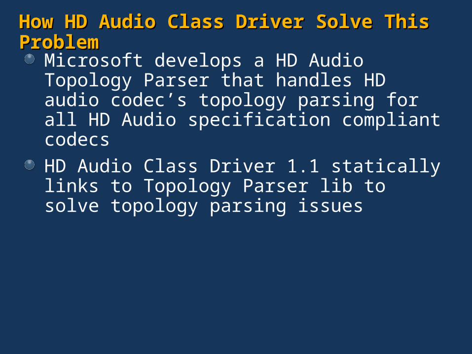
How HD Audio Class Driver Solve This ProblemHow HD Audio Class Driver Solve This Problem
Microsoft develops a HD Audio Topology Parser that handles HD audio codec’s topology parsing for all HD Audio specification compliant codecs
HD Audio Class Driver 1.1 statically links to Topology Parser lib to solve topology parsing issues

What Parser DoesWhat Parser Does
Topology Parser
Pin’s Configuration Default Settings
INPUTS
Outputs: Logical Devices
Wid 7 Wid 6 Wid 8
Headphone Device
Wid 7 Wid 6 Wid 8
MicIn Device
SPDIF Out
Wid 9 Wid 10
Wid 3 Wid 4 Wid 5
Wid 3 Wid 4 Wid 5
Wid 3 Wid 4 Wid 5
Multichannel Render
Wid 7 Wid 8
Spdif In
Parser DDI
Parser DDI
Codec Widget information (capability, connection list)

3rd Party IHVs Can Also Use Topology Parser3rd Party IHVs Can Also Use Topology Parser
3rd party driver can take advantage of Topology Parser by linking to this static library to replace their own parsing logics to simplify driver code
This Topology Parser will be released in the form of a static library. Its DDI is planned to be published when HD Audio Class Driver shipped in late 2005.

Role of Topology ParserRole of Topology Parser
HD Audio Codec
3rd
Party HD Audio Driver HD Audio Class Driver 3rd
Party HD Audio Driver
Codec C specific Knowledge Topology Parser (static lib) Topology Parser (static lib)
HD Audio Codec
HD Audio Codec
Provided by
IHV and ODM
Microsoft
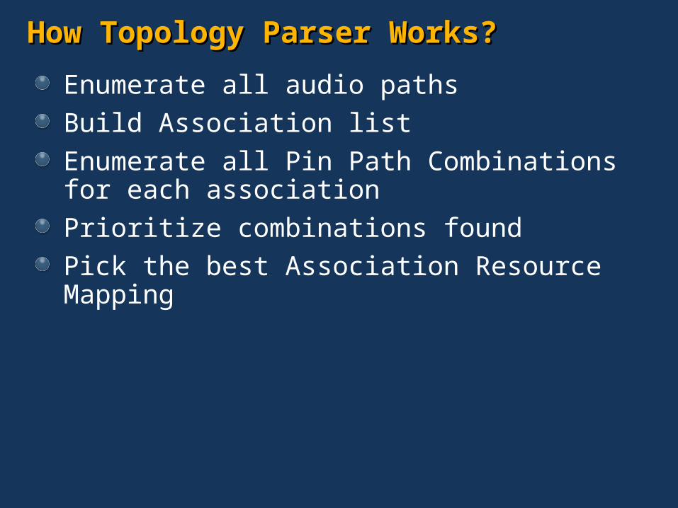
How Topology Parser Works?How Topology Parser Works?
Enumerate all audio paths
Build Association list
Enumerate all Pin Path Combinations for each association
Prioritize combinations found
Pick the best Association Resource Mapping
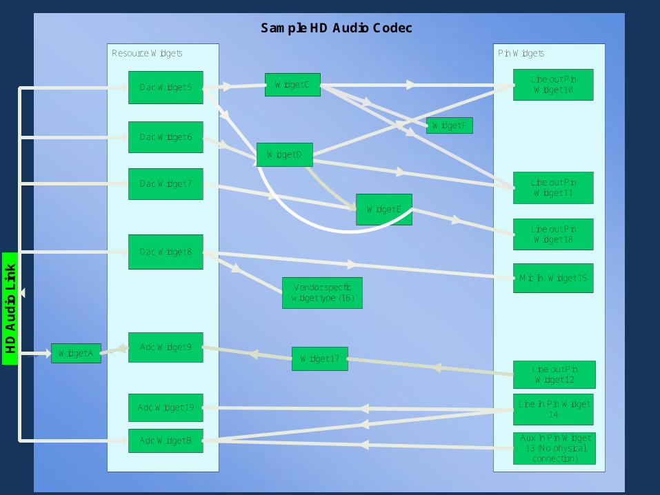
Resource Widgets Pin Widgets
HD
Au
dio
Lin
k
Dac Widget 5
Dac Widget 6
Dac Widget 8
Adc Widget 9
Adc Widget B
Widget C
Widget A
Widget F
Line out Pin Widget 10
Line out Pin Widget 11
Line out Pin Widget 12
Mic In Widget 15
Line In Pin Widget 14
Vendor specfic widget type (16)
Widget E
Widget 17
Aux In Pin Widget 13 (No physical
connection)
Widget D
Dac Widget 7
Line out Pin Widget 18
Adc Widget 19
Sample HD Audio Codec

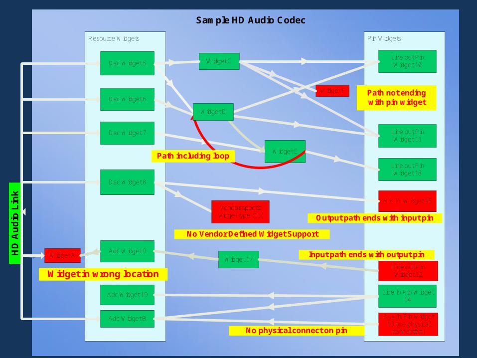
Enumerate All Audio PathsEnumerate All Audio Paths
Audio path: a path that audio data could flow through starting at a resource widget and ending at a pin widget
Not all the possible paths are valid. There are rules set by parser for what an invalid audio path is.
Invalid audio paths:Paths including loop
Paths including Vendor Defined Widget
Paths ending with a pin widget that has no physical connection
Output audio paths ending with input Pin
Input audio paths ending with output Pin
Paths contains widgets sitting between resource widget and HD Audio Link
Paths do not end with a pin widget
Resource Widgets Pin Widgets
HD
Au
dio
Lin
k
Dac Widget 5
Dac Widget 6
Dac Widget 8
Adc Widget 9
Adc Widget B
Widget C
Widget A
Widget F
Line out Pin Widget 10
Line out Pin Widget 11
Line out Pin Widget 12
Mic In Widget 15
Line In Pin Widget 14
Vendor specfic widget type (16)
Widget E
Widget 17
Path including loop
Widget in wrong location
Path not ending with pin widget
Aux In Pin Widget 13 (No physical
connection)
Widget D
Input path ends with output pin
Dac Widget 7
Line out Pin Widget 18
Output path ends with input pin
Adc Widget 19
No Vendor Defined Widget Support
No physical connect on pin
Sample HD Audio Codec
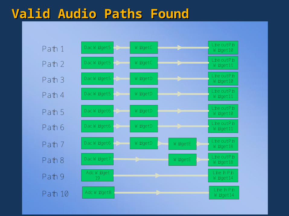
Valid Audio Paths FoundValid Audio Paths Found
Dac Widget 5 Widget CLine out Pin Widget 10
Dac Widget 5 Widget CLine out Pin Widget 11
Dac Widget 5 Widget DLine out Pin Widget 10
Dac Widget 5 Widget DLine out Pin Widget 11
Dac Widget 6 Widget DLine out Pin Widget 10
Dac Widget 6 Widget DLine out Pin Widget 11
Dac Widget 6 Widget D Line out Pin Widget 18
Widget E
Dac Widget 7 Line out Pin Widget 18
Widget E
Adc Widget 19
Line In Pin Widget 14
Adc Widget BLine In Pin Widget 14
Path 1
Path 2
Path 3
Path 4
Path 5
Path 6
Path 7
Path 8
Path 9
Path 10
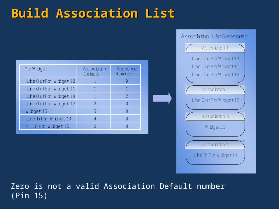
Build Association ListBuild Association List
Zero is not a valid Association Default number (Pin 15)
00Mic In Pin Widget 15
04Line In Pin Widget 14
03Widget 13
02Line Out Pin Widget 12
21Line Out Pin Widget 18
11Line Out Pin Widget 11
01Line Out Pin Widget 10
Sequence Number
Association Default
Pin Widget
00In Pin Widget 15
04Line In Pin Widget 14
03Widget 13
02Line Out Pin Widget 12
21Line Out Pin Widget 18
11Line Out Pin Widget 11
01Line Out Pin Widget 10
Sequence Number
Association Pin Widget
Association List Generated
Line Out Pin Widget 10
Line Out Pin Widget 11
Association 1
Line Out Pin Widget 18
Line Out Pin Widget 12
Association 2
Widget 13
Association 3
Line In Pin Widget 14
Association 4
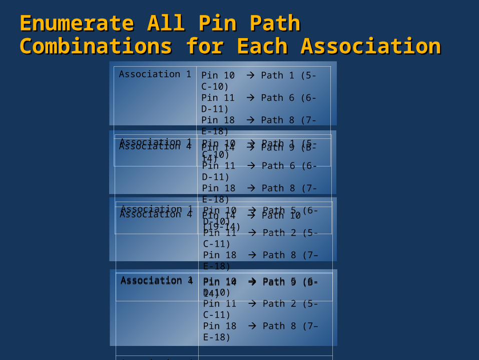
Enumerate All Pin Path Combinations for Enumerate All Pin Path Combinations for Each AssociationEach Association
Association 1 Pin 10 Path 5 (6-D-10)Pin 11 Path 2 (5-C-11)Pin 18 Path 8 (7–E-18)
Association 4 Pin 14 Path 10 (19-14)
Association 1 Pin 10 Path 1 (5-C-10)Pin 11 Path 6 (6-D-11)Pin 18 Path 8 (7-E-18)
Association 4 Pin 14 Path 9 (B-14)
Association 1 Pin 10 Path 5 (6-D-10)Pin 11 Path 2 (5-C-11)Pin 18 Path 8 (7–E-18)
Association 4 Pin 14 Path 9 (B-14)
Association 1 Pin 10 Path 1 (5-C-10)Pin 11 Path 6 (6-D-11)Pin 18 Path 8 (7-E-18)
Association 4 Pin 14 Path 10 (19-14)
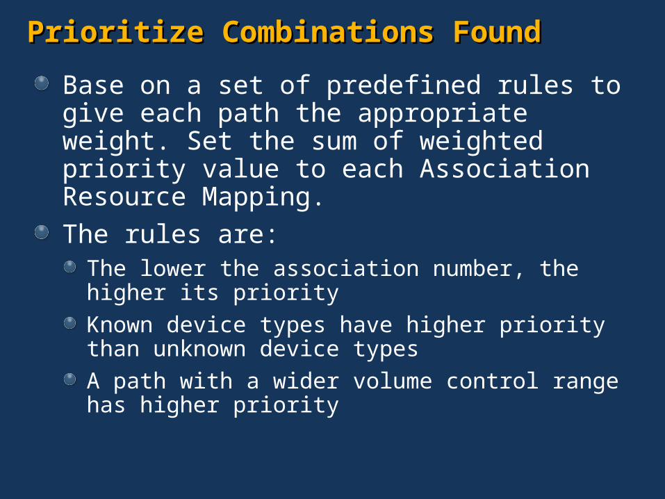
Prioritize Prioritize Combinations FCombinations Foundound
Base on a set of predefined rules to give each path the appropriate weight. Set the sum of weighted priority value to each Association Resource Mapping.
The rules are:The lower the association number, the higher its priority
Known device types have higher priority than unknown device types
A path with a wider volume control range has higher priority

1`
Pick the Best Association Pick the Best Association Resource Mapping
The highest sum of all weighted paths and associations will be chosen as the best Association Resource Mapping for final output.
Association 1 Pin 10 Path 1 (5-C-10)Pin 11 Path 6 (6-D-11)Pin 18 Path 8 (7-E-18)
Association 4 Pin 14 Path 9 (B-14)

Resource Widgets Pin Widgets
HD
Au
dio
Lin
k
Dac Widget 5
Dac Widget 6
Dac Widget 8
Adc Widget 9
Adc Widget B
Widget C
Widget A
Widget F
Line out Pin Widget 10
Line out Pin Widget 11
Line out Pin Widget 12
Mic In Widget 15
Line In Pin Widget 14
Vendor specfic widget type (16)
Widget E
Widget 17
Aux In Pin Widget 13 (No physical
connection)
Widget D
Dac Widget 7
Line out Pin Widget 18
Adc Widget 19
Sample HD Audio Codec
Logical Device 1Resource Widgets
HD
Au
dio
Lin
k
Dac Widget 5
Dac Widget 6
Adc Widget B
Widget C
Widget E
Widget D
Dac Widget 7
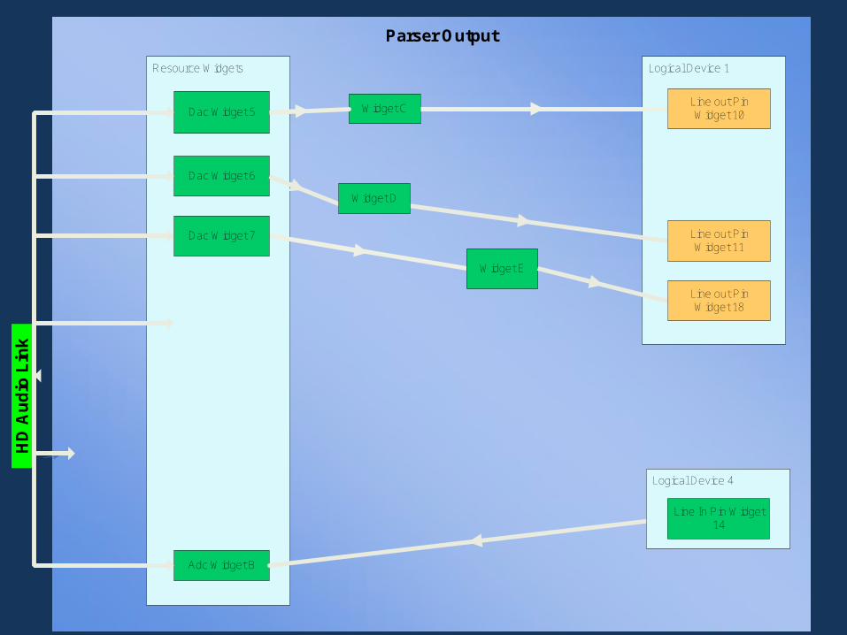
Parser Output
Logical Device 4
Line out Pin Widget 10
Line out Pin Widget 11
Line out Pin Widget 18
Line In Pin Widget 14
Use of Parser OutputUse of Parser Output
The Class Driver uses the parser's output to program widget connections and settings
For each logical device, class driver builds a Windows Kernel Streaming filter to expose its audio functionality to system

Programming Pin Configuration RegistersProgramming Pin Configuration Registers
The Microsoft Topology Parser relies on spec compliant HD Audio codecs
Follows Microsoft UAA “Pin Configuration Guidelines for High Definition Audio Devices” to ensure proper Pin Configuration Default settings
Detailed Pin Configuration register fields Detailed Pin Configuration register fields
FieldsPort Connectivity
Location
Default Device
Connection Type
Color
Misc.
Default Association
Sequence

PortPort Connectivity Field Connectivity Field
Used to indicate existenceThe Pin Widget can be either an external Jack or a fixed function device (like internal speakers) or it can be unconnected
0x1 means no physical connection
The Class Driver ignores Pin Widgets with this value set to 0x1
Location FieldLocation Field
Denotes Physical location of the Pin WidgetSet as appropriate
The Class Driver uses this information to describe the jack location to the end user

Default Device FieldDefault Device Field
The Class Driver uses Default Device field to determine what Logical Device to create
The Class Driver recognizes the following:Line Out, Speaker, HP Out, S/P-DIF Out, Line In, Mic In, CD, Aux and S/P-DIF In
Other devices supported by the parserDigital Other Out and Digital Other In
Not currently supportedModem Line Side, Modem Headset Side, Telephony, and Other
Interpretations and ClarificationsInterpretations and Clarifications
Specific Widget typesLine out - No build-in amplifier on the codec
Speaker - No build-in amplifier on the codec, but there is an external amp connected.
HP Out – There is a programmable build-in amplifier on the codec that can drive headphones. If the amp is turned off, the Pin acts like a Line Out pin (above)
Connection Type FieldConnection Type Field
Set as appropriate
Largely ignored by the Class Driver

Color FieldColor Field
16 possibilities – use them
Colors should be unique to each location
Pin with internal location should be set to color unknown (0x0)
The Class Driver uses this in it’s description of the jacks to the end user

Misc. FieldMisc. Field
Jack Detect Override0 means enabled
System must provide “Audio Jack Detection Circuits” before setting to 0.
1 means override (disabled)
This field should be enabled to empower dynamic device functionality

Default Association FieldDefault Association Field
Labels the priority of the Pin WidgetLower numbers mean higher priority
Association 0 is invalid
0xF means the pin is not associated to any other pin
The Class Driver uses this field to:Indicate groupings for multi-pin logical devices
Resolve resource disputes (higher priority device wins)

Sequence FieldSequence Field
Orders pins in an association
All sequence numbers in an association must be unique
The Class Driver generally uses this field to determine how to map channels in a multi-channel device.

Sequence Number MeaningsSequence Number Meanings
Ordering in HD Audio Spec 1.0Location information is missing
The Class Driver assigns meanings for clarity0 means Front Left & Front Right
1 means Front Center & Low frequency
2 means Back Left & Back Right
3 means Front Left of Center & Front Right of Center
4 means Side Left & Side Right
Special meanings (examples)(0,2) or (0,4) means Quadraphonic
(0,1,2) means Surround Sound Speakers
(0,1,2,4) means Home Theater Speakers
See Pin Config Guidelines for more info

Common Device ExperienceCommon Device Experience
SupportedRender
Line out, Speaker, Headphone and S/P-DIF Out
CaptureMicrophone, LineIn, CDIn, AuxIn and S/P-DIF In
Not SupportedDigital Other Out, Modem Line Side, Modem Handset side, Telephony, Digital Other In or Other (or Reserved)

Render DeviceRender Device
Can’t mix Line Out widgets and Speaker widgets in the same association
Generally, there are 1 to 4 pins in a render logical device association
Sequence numbers determine channel mapping
Single pin render devicesHeadphone
Line out
Speaker

Single Pin DevicesSingle Pin Devices
S/P-DIF Out DeviceNo analog functionality on audio path
Line In Device
Aux In Device
CD Device
S/P-DIF In Device
Microphone Device
Multi Purpose DevicesMulti Purpose Devices
Muxed Capture DeviceA collection of mutually exclusive input devices that share the same ADC
Mixed Capture DeviceA collection of devices that share the same ADC that may work at the same time
Redirected Headphone Render DeviceCombination render + headphone device where when the headphone is plugged in the output is redirected from the speakers to the headphone

Validate Pin ConfigurationsValidate Pin Configurations
Parser relies on the Pin Configuration Default for successful parsing – getting them set right is very important
Use UAATest.exeIt validates Pin Configuration Default settings
It exercises the same parser logics to validate codecs and exposes audio paths
UAATest also checks HD Audio Spec compliance
Let Microsoft know about inconsistencies (or issues with the output)

Call to ActionCall to Action
Use Microsoft Topology Parser to simplify and unify yours HD Audio device driver support
Follow guidelines in “Pin Configuration Guidelines for High Definition Audio Devices” for HD Audio Codec Pin Configuration Default programming
Help your OEM/ODM customers expose parser supported device types through system BIOS programming of HD Audio Pin Configuration Default values
Build UAA class driver compatible HD Audio solutions
Additional ResourcesAdditional Resources
Email uaa @ microsoft.com forMicrosoft UAA Pin Configuration Guidelines for High Definition Audio Devices, Release date TBD
UAA Hardware Design Guideline White Paper
UAATest.exe
Microsoft UAA overview white paper onhttp://www.microsoft.com/whdc/device/audio/uaa.mspx