haze-gard plus - Cole-Parmer -02.pdf · haze-gard plus Best.-Nr. 4725 Best.-Nr. 4726 ......
45
haze-gard plus Best.-Nr. 4725 Best.-Nr. 4726 haze-gard plus Cat. No. 4725 Cat. No. 4726 haze-gard plus N° de code 4725 N° de code 4726 E 03/06 238 013 796K haze-gard plus Best.-Nr. 4725 Best.-Nr. 4726 haze-gard plus Cat. No. 4725 Cat. No. 4726 haze-gard plus N° de code 4725 N° de code 4726 E 03/06 238 013 796K
Transcript of haze-gard plus - Cole-Parmer -02.pdf · haze-gard plus Best.-Nr. 4725 Best.-Nr. 4726 ......

haze-gard plus
Best.-Nr. 4725Best.-Nr. 4726
haze-gard plus
Cat. No. 4725Cat. No. 4726
haze-gard plus
N° de code 4725N° de code 4726
E03/06
238 013 796K
haze-gard plus
Best.-Nr. 4725Best.-Nr. 4726
haze-gard plus
Cat. No. 4725Cat. No. 4726
haze-gard plus
N° de code 4725N° de code 4726
E03/06
238 013 796K


haze-gard plus
Cat.No. 4725 and 4726
Table of Contents
1. Safety Information2. System Description3. Startup4. Operation5. Calibration
5.1 Additional Standards forMonitoring Test Equipment
5.2 Cleaning the Standards5.3 Changing Calibration Values
6. SET-UP Menu:Setting Instrument Parameters
7. Measurement Series andStatistics
8. Continuous Mode9. Parameters
10. Changing Lamps and Fuses11. Interface Description12. Technical Data13. Ordering Guide14. Error Messages
Technical Data are Subject to Alterations.

Foot Switch
LCD-Display
• Mains Switch• Voltage Selector• Fuse
Connection for• Power Cable• Foot Switch• PC• Printer
(RS-232)
Control Panel Haze Port
Clarity Port
Foot Switch
LCD-Display
• Mains Switch• Voltage Selector• Fuse
Connection for• Power Cable• Foot Switch• PC• Printer
(RS-232)
Control Panel Haze Port
Clarity Port

Before switching on the unit, makesure the voltage setting on the unitmatches the voltage of your poweroutlet. The unit must be pluggedinto a grounded outlet. Do noteliminate the ground protection byusing an ungrounded extensioncord.
Warning!Any break in the ground conductoreither inside or outside the unit, orany loosening of the groundconnection, may make the unithazardous to operate. Never breakthe ground connection intentionally!
Attention!For USA use only: DetachablePower Supply Cord - Listed, typeSVT or SJT, 18 AWG. Terminatesin parallel blade grounding type plug125 V, 15 A configuration.
Adjustments, Replacement ofParts, Maintenance and Repairs:Removing covers or components,except where this can be donewithout tools, may expose live parts.Connection terminals may also belive. Before replacing parts orperforming any adjustment,
1. Safety Information
!
maintenance or repair for which theunit must be opened, make sure theunit is disconnected from any powersource. Any adjustments,maintenance or repairs that mustunavoidably be performed with thepower on and the unit open shouldbe left to qualified personnel familiarwith the possible hazards.Capacitors inside the unit may stillcarry a charge even after the unithas been disconnected from thepower source. Be sure that allreplacement fuses are of thespecified type and size. Neverresort to using reconditioned fusesor short-circuiting.
Defects and Extreme UsageIf safe operation can no longer bepresumed, shut down the unit andsecure it against unintendedoperation. The unit must bepresumed unsafe to operate:
• if it shows visible damage• if it no longer operates• if it has been stored for long
periods under adverse conditions• after harsh treatment during
shipping
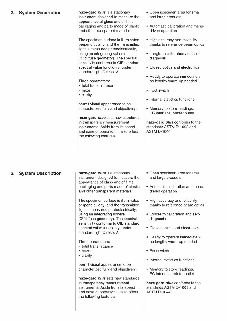
haze-gard plus is a stationaryinstrument designed to measure theappearance of glass and of films,packaging and parts made of plasticand other transparent materials.
The specimen surface is illuminatedperpendicularly, and the transmittedlight is measured photoelectrically,using an integrating sphere(0°/diffuse geometry). The spectralsensitivity conforms to CIE standardspectral value function y, understandard light C resp. A.
Three parameters:• total transmittance• haze• clarity
permit visual appearance to becharacterized fully and objectively.
haze-gard plus sets new standardsin transparency measurementinstruments. Aside from its speedand ease of operation, it also offersthe following features:
• Open specimen area for smalland large products
• Automatic calibration and menu-driven operation
• High accuracy and reliabilitythanks to reference-beam optics
• Longterm calibration and self-diagnosis
• Closed optics and electronics
• Ready to operate immediatelyno lengthy warm-up needed
• Foot switch
• Internal statistics functions
• Memory to store readings,PC interface, printer outlet
haze-gard plus conforms to thestandards ASTM D-1003 andASTM D-1044.
2. System Description
3. Startup IMPORTANT NOTES!Please read before you operatethe instrument:The unit has no special environ-mental requirements. However, it isimportant to observe the usualoperating conditions for electronicinstruments.
Avoid:
• Excessive oscillations andvibrations.
• Extreme ambient temperatures orrapid temperature changes.
• Relative humidity over 85 %.Avoid splashing with water orother liquids.
• Caustic and explosive chemicals,vapors and gases.
• Extreme electromagnetic fields.
• Intrusion of foreign objects orextraneous matter throughmeasuring apertures.
The instrument chassis is resistantto a number of solvents, but cannotbe guaranteed to withstand allchemicals. Use only a soft, dampcloth for cleaning. A little rubbingalcohol or mild soapsuds may beused to remove stubborn dirt.Clean the front lens of the clarityport only with a soft, lint-free cloth(preferably a damp optical wipe).
NEVER clean the interior of thedetector sphere (haze port)!
If the instrument malfunctions, donot attempt to repair it yourself. OurCustomer Service will be glad toprovide you with fast assistance.

Setting Up Always switch off the unit beforeplugging in or unplugging thevarious connectors (foot switch,printer cable and power cord).Make sure the voltage setting iscorrect. Otherwise the instrumentwill not operate properly orsafely.
• Unpack the unit and check forpossible damage sustained duringshipment (visual inspection).
• Before starting the unit for the firsttime, make sure all componentshave been delivered (for thepackage contents see Chapter 13,Ordering Guide).
• Check the voltage selector on theinstrument, and if necessarychange it to the right setting asfollows: Use an appropriate tool(No. 2 screwdriver) to remove thefuse insert below the power-cordreceptacle, and plug the insertback in so that the mark on thepower-switch housing coincideswith the required voltage range.
• Make sure the unit is still switchedoff. Plug the enclosed power cordinto the unit and into a groundedpower outlet.
• If applicable, plug the foot switchand the printer or PC connectioncable into the appropriatereceptacles.
!CAT.-NR.
S.-NR.
4725
427542
110/220 V 50/60 HZ 200 VA
BYK-Gardner GmbH82538 GeretsriedGermany
BYK-Gardner USASilver SpringMD-20910
USE ONLY WITH 250 VFUSES / EMPLOYERUNIQUEMENT AVEC
DES FUIBLES WITH 250 V
110-120 V
220-240 V
!T 1,6A 250V (115V)T 1,0A 250V (230V)
RS-232
foot-switch
MADE IN GERMANY

Power-Up
Before switching the unit on,remove the protective cover/darkstandard from the haze port. Turnon the unit at the power switch onthe left side.
The logo, version number and acopyright message will appear onthe display.
The unit will run a self-diagnostictest. If any system components areoutside the tolerance range, anerror message will appear.
SELF DIAGNOSTIC
Lamp: okChopper: okShutter: ok
Version: 1.0 Copyright 1994
Version: 1.0 Copyright 1994

STATUS
Transmission Std. 100.0%
Clarity Standard 75.5%
STATUS
Lamp Status 100%
Sphere Coating 100%
Time: 7.54 am Date: 14.06.1994
STATISTIC-MEMORY
T: n= 4 H: n= 5 C: n= 0
STATISTIC-MEMORY
T+H: n= 10 T+C: n= 0 H+C: n= 0 T+H+C: n= 5
The stored calibration values willappear on the display.
The time and date needed forprintouts can be updated with SET-UP. If the lamp status is below50 %, change the lamp (Chapter10). If the sphere coating hasdropped below 50 %, we suggestyou contact Customer Service toarrange for testing.
Number of readings stored in theunit.
STATUS
Transmission Std. 100.0%
Clarity Standard 75.5%
STATUS
Lamp Status 100%
Sphere Coating 100%
Time: 7.54 am Date: 14.06.1994
STATISTIC-MEMORY
T: n= 4 H: n= 5 C: n= 0
STATISTIC-MEMORY
T+H: n= 10 T+C: n= 0 H+C: n= 0 T+H+C: n= 5
The stored calibration values willappear on the display.
The time and date needed forprintouts can be updated with SET-UP. If the lamp status is below50 %, change the lamp (Chapter10). If the sphere coating hasdropped below 50 %, we suggestyou contact Customer Service toarrange for testing.
Number of readings stored in theunit.

WARM-UP
Only about 2 minutes are neededfor warm-up.
As soon as the instrument hascompleted the self-diagnosis andstatus displays, it immediately goesinto the mode that was active at thelast shutdown. It is now ready foroperation. Before you can takemeasurements after starting theinstrument for the first time, it mustbe calibrated (see Chapter 5).
operate set up referencetrans-
mittance haze clarity
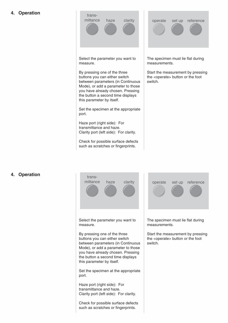
4. Operation
Select the parameter you want tomeasure.
By pressing one of the threebuttons you can either switchbetween parameters (in ContinuousMode), or add a parameter to thoseyou have already chosen. Pressingthe button a second time displaysthis parameter by itself.
Set the specimen at the appropriateport.
Haze port (right side): Fortransmittance and haze.Clarity port (left side): For clarity.
Check for possible surface defectssuch as scratches or fingerprints.
The specimen must lie flat duringmeasurements.
Start the measurement by pressingthe <operate> button or the footswitch.
operate set up referencetrans-
mittance haze clarity
4. Operation
Select the parameter you want tomeasure.
By pressing one of the threebuttons you can either switchbetween parameters (in ContinuousMode), or add a parameter to thoseyou have already chosen. Pressingthe button a second time displaysthis parameter by itself.
Set the specimen at the appropriateport.
Haze port (right side): Fortransmittance and haze.Clarity port (left side): For clarity.
Check for possible surface defectssuch as scratches or fingerprints.
The specimen must lie flat duringmeasurements.
Start the measurement by pressingthe <operate> button or the footswitch.

A message on the display will tellyou if it is necessary to changemeasurement ports (when multipleparameters have been selected).Move the specimen to theappropriate port and start themeasurement by pressing the<operate> button or foot switch.The readings will appear on thedisplay.
Control panel:
Cursor keys:Used in SET-UP mode to selectindividual menu items and setvalues such as time (Chapter 6). Inany measuring mode, these keysare used to switch statisticsfunctions on and off, and to deletevalues from the statistics memory(Chapter 7).
H 14.7
delete all
delete last
statistic result
on/off on/off
operate set up referencetrans-
mittance haze clarity
delete all
delete last
statistic result
on/off on/off

operate set up reference
In the measuring modes, startsmeasurements.In SET-UP mode, confirms theselected function.
Calls up the SET-UP menu(Chapter 6).
Used in Continuous Mode todetermine the reference value fortotal transmittance (Chapter 8).
operate set up reference
In the measuring modes, startsmeasurements.In SET-UP mode, confirms theselected function.
Calls up the SET-UP menu(Chapter 6).
Used in Continuous Mode todetermine the reference value fortotal transmittance (Chapter 8).

5. Calibration State-of-the-art technology and thereference-beam principle mean thatcalibration is needed onlyinfrequently. We recommend acalibration interval of two months.
Calibration is also necessary:
• at the first startup
• in the event of a drastic change inambient temperature (for example,after moving the unit to a new site)
• if "Please Recalibrate" appears onthe display (for example, afterstored calibration values havebeen modified).
To ensure accurate calibration, useonly original standards fromBYK-Gardner.
Do not touch the reference surface.Protect it against scratching.Even with careful treatment,ambient conditions may alter astandard’s values over time. Forthat reason, have Customer Servicecheck your standards regularly(once a year) against primarystandards.
Make sure the values displayedduring calibration match the data forthe standards you use, in order toavoid mixing up or accidentallychanging the calibration values (seeSection 5.3).
To calibrate:
CAUTION: Make sure thecalibration standards are cleanand free from scratches!
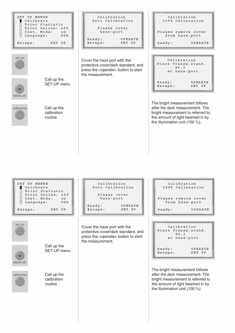
Call up theSET-UP menu
Call up thecalibrationroutine
Cover the haze port with theprotective cover/dark standard, andpress the <operate> button to startthe measurement.
delete all
reference
set up
Calibration Zero Calibration
Please cover haze-port
Ready: OPERATEEscape: SET UP
Calibration 100% Calibration
Please remove cover from haze-port
Ready: OPERATE
CalibrationPlace Transm.stand. 86.3 at haze-port
Ready: OPERATEEscape: SET UP
SET UP MENUE Calibrate Print Statistic Print Online: off Cont. Mode: on Language: USA
Escape: SET UP
The bright measurement followsafter the dark measurement. Thebright measurement is referred tothe amount of light beamed in bythe illumination unit (100 %).

If you have selected a transmittanceother than 100 % in SETUP (seeSection 5.3 and Chapter 9), put theappropriate standard in the hazeport.If you have selected 100 % for thetransmittance standard, you onlyneed to clear the instrument’s beampath.
Start the brightmeasurement
Now perform calibration for clarity.
Place the clarity standard at theclarity port (left side).
Start calibration
If the calibration procedure iscancelled with SET-UP, the lastcalibration in effect remains valid.
This concludes calibration. Theinstrument goes to the measuringmode that was active before thecalibration.
operate operate
CalibrationPlace clarity stand. 75.5 at clarity-port
Ready: OPERATEEscape: SET UP
Note: If fluctuating or obviouslywrong values are displayed aftercalibration, repeat the calibration.This symptom means the haze portwas either improperly covered (forthe dark measurement) or partiallystill covered (for the brightmeasurement) during themeasurements.

5.1 Additional Standards forMonitoring Test Equipment
To check proper operation of theinstrument, measurements withspecial test standards should beperformed at regular intervals(about once every three months).The appropriate test standards arelisted in the Ordering Guide.
The displayed readings should fallwithin the specified values for thestandard. If they do not, check thatthe standard was clean and that thedevice was properly calibrated. Ifcleaning the standard andrecalibration do not correct theerror, please contact CustomerService.
5.2 Cleaning the Standards
Calibration with a dirty or damagedstandard may severely affect theaccuracy of measurements.
Standard surfaces are very delicate.Be very careful when cleaningthem.
Use a fresh, soft cloth, and washthe standards in running or standingcold water. Do not apply ascrubbing action or heavy pressure.Make sure no large particles thatmight damage the surface adhere tothe cloth.
Do not use aggressive cleaners likesolvents, rubbing alcohol,trichloroethylene, benzine, or strongalcohols, acids or lyes. Mostchemical cleaners or polishes willcause damage.
To remove stubborn dirt, add a littlehousehold dish detergent to thewater. Rinse with distilled water.Dry with compressed air and blowoff any dust or lint.
Never rub the standard dry! Therubbing action may causescratches from surface dust.
Precise calibration is possible onlywith flawless standards. If visualappearance or measurement errorssuggest that a standard is compro-mised, we’ll be glad to check it.

5.3 Changing Calibration Values
The values for the calibrationstandards are stored in theinstrument. In automatic calibration,this data is associated with therespective standards.
In some cases it may be necessaryto adjust the stored data to a newstandard, for example if thesupplied standard has deteriorateddue to aging.
To input new standard values,select the "Change CalibrationValue" function in the SET-UPmenu, and confirm with the<operate> button.

delete all
delete last
delete all
delete last
statistic
on/off
result
on/off
Initialize Instr.
Old NewT Std 100 100C Std 75.5 75.5
Save Data: OPERATEEscape: SET UP
T Std = 100
1 000 ↑Confirm: OPERATEEscape: SET UP
Change Cal Value
Input Trans Std Input Clarity Std Save Std Values
Escape: SET UP
Changethe valueandconfirmwith<operate>.
Pressing the <operate> buttonsaves the new setting for thestandard value and returns you tothe "Change Calibration Value"submenu. Pressing the <set up>button rejects the change andretains the old standard value.
These new values remain valid onlyuntil the unit is switched off. When itis switched back on, the old valuesare restored.
The "Save Standard Values"function serves to save the resetstandard values permanently, sothat they are retained even after theinstrument is switched off. If achange has been confirmed with<operate>, a recalibration isnecessary after exiting from the"Change Calibration Value"submenu.
Select thestandard youwant to change,and confirm with<operate>.
In the four-digit display, the lastnumber indicates the number ofdigits after the decimal point.
Select thedecimalplace tobemodified.
delete all
delete last
delete all
delete last
statistic
on/off
result
on/off
Initialize Instr.
Old NewT Std 100 100C Std 75.5 75.5
Save Data: OPERATEEscape: SET UP
T Std = 100
1 000 ↑Confirm: OPERATEEscape: SET UP
Change Cal Value
Input Trans Std Input Clarity Std Save Std Values
Escape: SET UP
Changethe valueandconfirmwith<operate>.
Pressing the <operate> buttonsaves the new setting for thestandard value and returns you tothe "Change Calibration Value"submenu. Pressing the <set up>button rejects the change andretains the old standard value.
These new values remain valid onlyuntil the unit is switched off. When itis switched back on, the old valuesare restored.
The "Save Standard Values"function serves to save the resetstandard values permanently, sothat they are retained even after theinstrument is switched off. If achange has been confirmed with<operate>, a recalibration isnecessary after exiting from the"Change Calibration Value"submenu.
Select thestandard youwant to change,and confirm with<operate>.
In the four-digit display, the lastnumber indicates the number ofdigits after the decimal point.
Select thedecimalplace tobemodified.

delete all
delete all
delete last
operate
set upset up
SET UP MENUE Calibrate Print Statistic Print Online: off Cont. Mode: on Language: USA
Escape: SET UP
SET UP MENUE Beeper : off Adjust Date Adjust Time Display Contrast Change Cal Value Service MenueEscape: SET UP
6. SET-UP Menu:Setting InstrumentParameters
The SET-UP menu is used to setinstrument parameters and performcalibration.
Calls up theSET-UP menu.
An operatorinstructionmessageappears.
Displays the firstSET-UP page.
Use the Up andDown cursorkeys to selectthe menuitem you want orto display thenext page.
Calls up orswitches theselectedfunction, andconfirmschanges.
Exit the SET-UPmenu withoutconfirmingchanges.
delete all
delete all
delete last
operate
set upset up
SET UP MENUE Calibrate Print Statistic Print Online: off Cont. Mode: on Language: USA
Escape: SET UP
SET UP MENUE Beeper : off Adjust Date Adjust Time Display Contrast Change Cal Value Service MenueEscape: SET UP
6. SET-UP Menu:Setting InstrumentParameters
The SET-UP menu is used to setinstrument parameters and performcalibration.
Calls up theSET-UP menu.
An operatorinstructionmessageappears.
Displays the firstSET-UP page.
Use the Up andDown cursorkeys to selectthe menuitem you want orto display thenext page.
Calls up orswitches theselectedfunction, andconfirmschanges.
Exit the SET-UPmenu withoutconfirmingchanges.

statistic
on/off
result
on/off
delete all
delete last
When entering numbers:
Changedesireddecimalplace
Changevalue
Explanation of Menu Items
Calibrate: Calls up the calibrationroutine (Chapter 5).
Print Statistics: Sends thereadings in the current statisticsmemory to the connected printer.
Print Online: Sends readings tothe connected printer as soon asthey are taken.
Continuous Mode: Performsautomatic, continuous repetition ofmeasurements (Chapter 8).
Language: Allows you to changelanguages, using the cursor key.The cursor position shows theselected language.
Beeper: Sets the instrument toemit a beep signal after ameasurement is completed.
Adjust Date: Allows you to use thecursor keys to change the date.Years before 1980 will not beaccepted.
Adjust Time: Allows you to use thecursor keys to set the internal clock.
Display Contrast: Allows you toadjust display contrast, using theleft and right cursor keys.
Change Calibration Value: Callsup a submenu to change the savedcalibration values (Chapter 5).
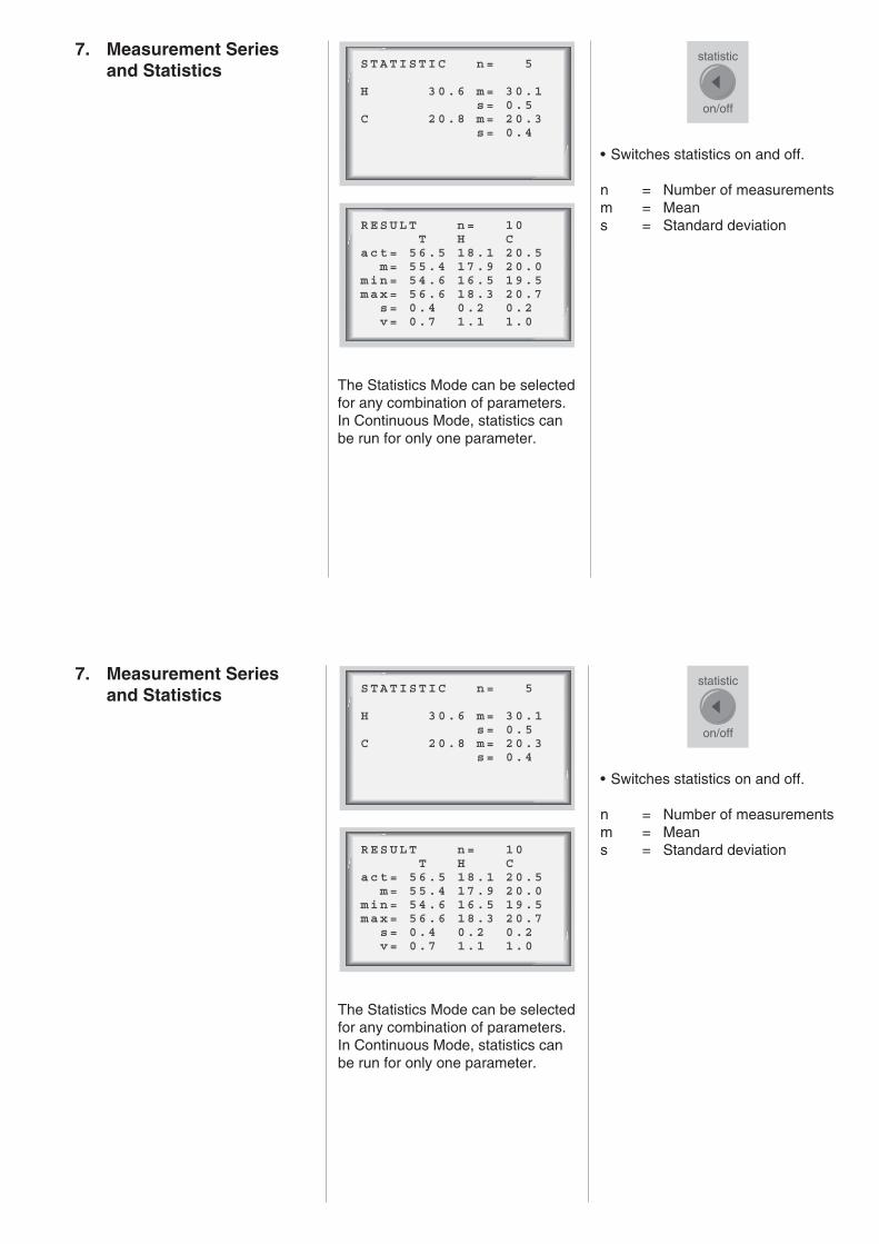
RESULT n= 10 T H Cact= 56.5 18.1 20.5 m= 55.4 17.9 20.0min= 54.6 16.5 19.5max= 56.6 18.3 20.7 s= 0.4 0.2 0.2 v= 0.7 1.1 1.0
statistic
on/off
STATISTIC n= 5
H 30.6 m= 30.1 s= 0.5C 20.8 m= 20.3 s= 0.4
7. Measurement Seriesand Statistics
The Statistics Mode can be selectedfor any combination of parameters.In Continuous Mode, statistics canbe run for only one parameter.
• Switches statistics on and off.
n = Number of measurementsm = Means = Standard deviation

result
on/off
delete last
• Switches all statistical data onand off
act = Last measured value; inContinuous Mode, this isthe value for the insertedspecimen
m = Mean valuemin = Minimum valuemax = Maximum values = Standard deviationv = Variance coefficient
V= 100 × s/ m %
In Statistics Mode, measured valuesare saved and retained when youswitch to a different parameter orturn the instrument off. Savedvalues can be transferred to aprinter or PC via the serial interface.A measurement series that hasbeen saved previously can becalled back up and continued, aslong as it has not been deleted inthe meantime. Calibration valuescannot be changed while a series isrunning, since this would falsify thestatistical results.
The last measurement to have beensaved is deleted.The counter variable n isdecremented by 1.
s= 1n-1
n
i=1∑ (x-x)2
i
s= 1n-1
n
i=1∑ (x-x)2
i
delete all
All statistics in the memory aredeleted.The delete function affects only thememory area in use for the currentparameters.
delete all
All statistics in the memory aredeleted.The delete function affects only thememory area in use for the currentparameters.

set up
trans-mittance haze clarity
Transmittance Measurement
Please place sample at haze-port
Ready: OPERATE
8. Continuous Mode In the normal measuring mode,individual measurements arestarted by pressing <operate>. InContinuous Mode, on the otherhand, measurements are repeatedand updated constantly. This letsyou "run" a rather larger area of thespecimen and get an impression ofnonuniform zones.
Continuous Mode is possible onlyfor a single parameter.
Select"ContinuousMode" in theSET-UP menu.
Select the desired parameter. Theparameter can be changed at will.
The haze measurement needs thevalue for total transmittance as areference for the measuredspecimen. When applicable, aprompt to this effect will appear onthe display.

reference
operate
statistic
on/off
result
on/off
operate
After changing a specimen,always be sure to update the re-ference measurement for the newspecimen before proceeding.
Put specimen athaze port
Performreferencemeasurement
When specimens have only slightdifferences in total transmittance,you need not update the referencerepeatedly.
Statistical evaluations can also beperformed in Continuous Mode.The values measured here arewritten to the same memory area asin normal measuring mode.
Switch onStatisticsor Results
Use <operate>or the foot switchto save the valueto the statisticsmemory.
Stand-by Mode: To save the lamp,after a certain interval ContinuousMode is interrupted and Stand-byMode appears on the display. Themeasurements are continued whena significant change occurs in thebeam path (for example, when anew specimen is put in place).

9. Parameters Appearance of TransparentMaterials
When a parallel beam of lightstrikes a transparent specimen, anumber of effects may result,depending on the nature of thematerial:
• Homogeneous material with asmooth surface
Some of the incident light will bereflected from surfaces, and somewill pass through the specimenunaltered. The specimen willappear glossy and crystal clear.
The intensity of the transmittedlight will be diminished by theinherent absorbance of thematerial, dyes or pigments.
• Rough surfaces and internalscattering
Diffuse scattering will decrease anobject’s imaging quality. Particlesinside the material or structures on
its surface may act as "scatterers".The more scatterers are present,the greater the amount ofscattered light; the distribution ofscattered light in space is relatedto the scatterers’ size distribution.The scattering behavior of aspecimen will determine itsappearance. Two differentcomponents can be clearlydistinguished visually (Fig. 1).
• Wide-angle scattering - Haze
Wide-angle scattering diffuseslight uniformly in all directions, andthe light intensity per angle issmall. This reduces contrast andresults in a milky or cloudyappearance. This effect is calledhaze.
• Narrow-angle scattering – Clarity
Narrow-angle scattering deflectslight in small angles, so that thelight intensity is concentratedwithin this narrow angular range.
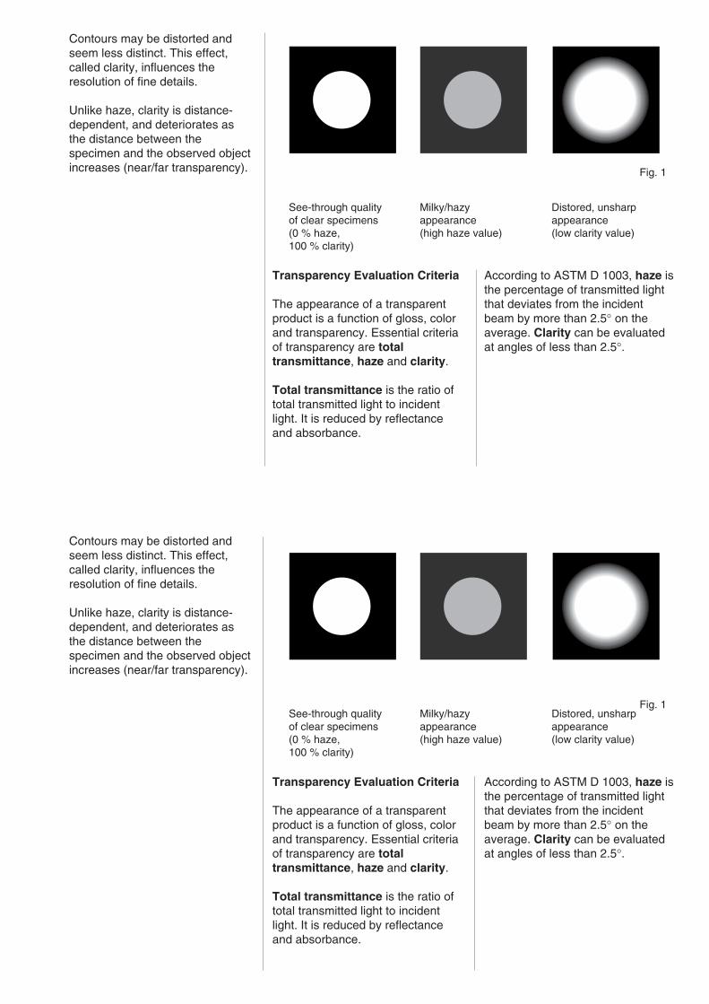
According to ASTM D 1003, haze isthe percentage of transmitted lightthat deviates from the incidentbeam by more than 2.5° on theaverage. Clarity can be evaluatedat angles of less than 2.5°.
Fig. 1
See-through qualityof clear specimens(0 % haze,100 % clarity)
Milky/hazyappearance(high haze value)
Distored, unsharpappearance(low clarity value)
Contours may be distorted andseem less distinct. This effect,called clarity, influences theresolution of fine details.
Unlike haze, clarity is distance-dependent, and deteriorates asthe distance between thespecimen and the observed objectincreases (near/far transparency).
Transparency Evaluation Criteria
The appearance of a transparentproduct is a function of gloss, colorand transparency. Essential criteriaof transparency are totaltransmittance, haze and clarity.
Total transmittance is the ratio oftotal transmitted light to incidentlight. It is reduced by reflectanceand absorbance.
According to ASTM D 1003, haze isthe percentage of transmitted lightthat deviates from the incidentbeam by more than 2.5° on theaverage. Clarity can be evaluatedat angles of less than 2.5°.
Fig. 1See-through qualityof clear specimens(0 % haze,100 % clarity)
Milky/hazyappearance(high haze value)
Distored, unsharpappearance(low clarity value)
Contours may be distorted andseem less distinct. This effect,called clarity, influences theresolution of fine details.
Unlike haze, clarity is distance-dependent, and deteriorates asthe distance between thespecimen and the observed objectincreases (near/far transparency).
Transparency Evaluation Criteria
The appearance of a transparentproduct is a function of gloss, colorand transparency. Essential criteriaof transparency are totaltransmittance, haze and clarity.
Total transmittance is the ratio oftotal transmitted light to incidentlight. It is reduced by reflectanceand absorbance.
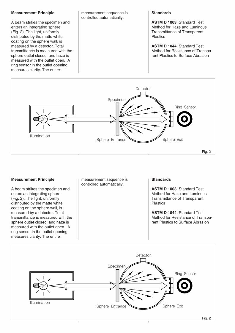
Fig. 2
Measurement Principle
A beam strikes the specimen andenters an integrating sphere(Fig. 2). The light, uniformlydistributed by the matte whitecoating on the sphere wall, ismeasured by a detector. Totaltransmittance is measured with thesphere outlet closed, and haze ismeasured with the outlet open. Aring sensor in the outlet openingmeasures clarity. The entire
measurement sequence iscontrolled automatically.
Standards
ASTM D 1003: Standard TestMethod for Haze and LuminousTransmittance of TransparentPlastics
ASTM D 1044: Standard TestMethod for Resistance of Transpa-rent Plastics to Surface Abrasion
Illumination
Detector
Sphere Exit
Ring Sensor
Specimen
Sphere Entrance

Notes:
• For values of less than 10 %, themeasurement range is auto-matically switched over to adisplay with two decimal places.
• In taking a measurement, themean is taken across the illumina-ted surface of the specimen. Sinceit cannot be assumed that opticalcharacteristics will be uniform overthe entire surface of the specimen,we recommend taking readings ata variety of points on the speci-men, and using the mean.
• There is little sense in takingreadings from dirty, scratched orotherwise damaged areas of thespecimen, unless you want toobtain the measurements as anindication of the severity of suchdamage, for example inmeasuring abrasion resistance(Taber Abraser).
• Specimen surfaces must be asplane-parallel as possible; awedge shape will deflect light.
• When taking comparativereadings note the specimenthickness, since absorbance andscattering increase in directproportion to thickness.
• Differences in reflectioncharacteristics may affecttransparency measurements.Particularly when specimens areglossy on one side and dull on theother, the same surface shouldalways be directed toward thesphere aperture.
• Positioning the specimen at thesphere inlet reflects light from thespecimen within the sphere. Thisimproves the sphere’s efficiency,and the measured totaltransmittance will be slightlyhigher.For completely clear specimens,you can obtain precisetransmittance values by keepingthe specimen at the clarity portduring the transmittancemeasurement.Specimens with high levels ofscatter should always be placed at
the haze port. Here werecommend calibrating theinstrument with a previouslymeasured transmittance standard(see Section 5.3). This standardmust have a surface reflectivitysimilar to that of the specimens tobe measured.
• Optical-quality cuvettes withplane-parallel walls and an edgelength of at least 50 mm may beused to take readings on liquids.Appropriate cuvettes are listed inthe Ordering Guide.
• In practice, it may be significant toknow whether scattering is causedby internal scatterers or surfacestructure. In these cases, surfacescattering can be eliminated byimmersing the specimen duringthe readings in a liquid with thesame refractive index as thespecimen. Only bulk scattering willthen come into play.

!
10. Changing Lamps andFuses
Changing Lamps
CAUTION: Before changing alamp, switch off the instrument,unplug it from the power source,and let the lamp cool.
Remove the cover above thedisplay by unscrewing the twoscrews and pushing the covertoward the back.Unplug the lamp unit from the cableconnecting it to the rest of the unit.The lamp unit is secured in placewith a knurled screw. Unscrew thisand carefully withdraw the lamp unitfrom its clip.
Do not reach into the interior ofthe instrument, and be carefulnot to let anything drop throughthe instrument opening.
Now insert the new lamp unitcarefully into its seating. Do nottouch the glass body of the lampwith your bare fingers. Oily residueswill burn permanently onto theglass. If you unintentionally touch
the glass, it must be cleaned withrubbing alcohol. Secure the lampunit with the knurled screw and plugit back onto the cable. Make sure noobjects have been left inside theinstrument, and then close thecover by slipping it into the guidefrom the rear and fastening it to thechassis with the two screws.
The instrument must be recalibratedafter a lamp is changed.

!
Changing Fuses
CAUTION: Before changing afuse, switch off the instrumentand unplug it from the powersource.
With a suitable tool (No. 2 screw-driver), remove the fuse holder fromthe fuse housing (on the left side ofthe unit). Replace the defective fusewith a new one. Use only the type offuse specified in the TechnicalSpecifications (Chapter 12). Nowreinsert the fuse holder so that themark points to the appropriate linevoltage.
Never use reconditioned fuses orfuses of the wrong type or size.The mark on the fuse housing mustcoincide with the mark for theappropriate line voltage on the linevoltage selector.

The instrument is equipped with aserial interface (RS-232) by way ofwhich the instrument can becontrolled and measurement datacan be processed further by a PC,or data can be output on anappropriate printer. The unit has a9-pin Sub-D connector for datatransfer.
haze-gard plus PC
3 TxD RxD 32 RxD TxD 27 RTS CTS 58 CTS RTS 45 GND GND 7
1 6
59
11. Interface Description Transfer Rate and Format
Serial asynchronous transfer ispreset on the instrument, and isperformed with the following format:
9600 baud, 8 data bits, no parity,1 stop bit.
Control Commands
4Fh (ASCII code for ‘0’) Startsonline operation.
The instrument transmits a 4Fh andsends back a 21h as theacknowledgement signal.
• The instrument controls aredisabled, except for the <operate>and <reference> buttons and thefoot switch.
Then the instrument status(10 bytes) is transmitted to thecomputer.

• Selected language (byte 1)00h = German01h = English02h = French03h = Italian04h = Spanish
• Current mode (byte 2)00h = T01h = H02h = C03h = T&H04h = T&C05h = H&C06h = T&H&C
• Number of valid individualreadings (byte 3)00h = Only first reading is valid01h = First and second readings
are valid02h = All three readings are valid
• Sample, Statistics or Results(byte 4)00h = Sample01h = Statistics02h = Results
• Continuous Mode (byte 5)00h = No01h = Yes
• Calibration valid (byte 6)00h = No01h = Yes
• Beep (byte 7)00h = Off01h = On
• Display contrast
• Versionnumber LSB
• Versionnumber MSB
The following conventions apply foroperating the instrument controlsfrom the PC:
00h = Statistics01h = Delete last02h = Results03h = Delete all04h = Operate05h = Setup06h = Reference08h = Transmittance09h = Haze
0Ah = Clarity
The instrument acknowledges eachcontrol command with 2 characters(bytes).First byte: control command (echo)Second byte: "!" (21h)
If the PC sends the instrument a 4(= operate) while the instrument isin any measuring mode, a meas–urement will be started. When thefirst measurement reading isavailable, the instrument sends a66h (ASCII code for lower-case ‘f’)to the PC (readout). Then themeasured values are transmitted.Data is always transmitted for allthree parameters. The status stringcontains the information about thevalidity and sequence of readings(bytes 2 and 3).
For the measured value, four ASCIIcharacters followed by a 0 byte aretransmitted.
Example: 39h+35h+2Ch+34h+00his equivalent to a measured value of95.4.

For values over 99.9, the fourth byteis always a blank (20h). Thenumber of decimal digits matchesthe value appearing on theinstrument display.
If the specimen must be movedfrom the haze port to the clarity port,a 77h (ASCII code for lower-case‘w’) is sent between the associatedmeasured values.
In Continuous Mode, only onemeasured value is transmitted tothe PC if the PC has previouslytransmitted a 04h (= operate). Inthis case, only the measured valuefor the current measuring geometryis transmitted (only one geometry ispossible in Continuous Mode). Forthis, the instrument sends the PC a66h (ASCII code for lower-case ‘f’)and then four (ASCII) characters forthe value, as for individualmeasurements. The transferconcludes with a 0 byte. Since onlyone parameter can be measuredwhile the instrument is inContinuous Mode, define theparameter you want as a single
parameter before activatingContinuous Mode.
Online Mode is terminated with 50h(ASCII code for ‘P’).
Readout of a Statistics Memory
Sending 51h (ASCII code for ‘Q’)notifies the instrument that astatistics memory is to be read out.The instrument acknowledges therequest and waits for the number ofthe statistics memory thatcorresponds with the associatedmeasuring mode (e.g., 06h =T&H&C).
After receipt of the number of thestatistic memory, the number ofmeasured values is transferred.Then come the measured values(2 byte = 1 Integer LSB, MSB) andafter this time and date when themeasurements were taken (time = 2bytes, mm:hh; date = 3 bytes,dd:mm:yy). The transmitted year isthe difference between the currentyear and 1980.
Following the sequence of theselected geometry, values aremultiplied by 100 (up to 2 decimalplaces possible) and transmitted tothe PC as integers (2 bytes LSB,MSB).
Readout of a statistics memory isalso possible in Online Mode.

12. Technical Specifications MeasuringGeometries: 0°/diffuse
MeasuringAperture: 25.4 mm diameter
Measuring Field: 18.0 mm diameter
Color Sensitivity: Spectralconformity to CIEstandard spectralvalue function y,under
Illuminant: CIE-C (Cat.No.4725)CIE-A (Cat.No.4726)
Measuring Range:Transmittance: 0-100%Haze: 0-100%Clarity: 0-100%
DisplayResolution: 0.01 unit (in range
0.00-9.99)0.1 unit (in range10.0-99.9)
Repeatability: ± 0.1 units*Reproducibility: ± 0.4 units*
Measuring Time: 1-6 seconds(depending onmode)
StatisticsMemory: 7 x 999
measurements,3 V lithiumbattery backup(CR 2450N FH)
Interface: serial RS-232,interactive
Connectors:RS-232: 9-pin Sub-DFoot switch: 15-pin Sub-D
Power Supply: 230 V/50 Hz,115 V/60 Hz
Power Draw: max 200 VA
Fuses: Slo-blo 1.0 A;250 V (230 Vpower supply)

Slo-blo 1.6 A;250 V (115 Vpower supply)
OperatingTemperature: +10°C to +40°C
StorageTemperature: 0°C to +50°C
Dimensions: 340 x 670 x240 mm
Weight: 18 kg
SpecialFeatures: Longterm
calibration, nowarm-up time,automaticmeasurementrange fitting.
*Standard deviation
Technical modifications may bemade without notice.

Description Cat.No.
haze-gard plus (Illuminant C) 4725haze-gard plus (Illuminant A) 4726
basic version, consisting of:• Instrument• Foot Switch• Clarity Calibration Standard• Dark Standard• 2 Foil Holders (6 cm and 12 cm)• Power Cord• Box for 8 Standards
Accessories
Foot Switch 4731
Connection Cable• For PC and printer
Sub-D 9/25 pin 4613
Portable, Serial40-column printer• Recharger 230 V 6650• Recharger 115 V 6649
Printer Paper, 20 Rolls 6648
Holder for Taber HazeAttachment 4735
Optical Cells for Liquids, 50 mm• Fixed path 2,5 mm 6180• Fixed path 4,0 mm 6181• Fixed path 5,0 mm 6182• Fixed path 10,0 mm 6183
Transmission Cell Holder 4739
Sample Holder for Films• For films larger than 17 x 10 cm,
max. thickness of 0,5 mm 4738
Lamp 4736
Standards• Haze approx. 1 % 4740• Haze approx. 5 % 4741• Haze approx. 10 % 4742• Haze approx. 20 % 4743• Haze approx. 30 % 4744• Haze, Set of 5 4745• Transmission approx. 30 % 4750• Transmission approx. 50 % 4751• Transmission approx. 70 % 4752• Transmission approx. 90 % 4753• Transmission, Set of 4 4754• Clarity Reference Standard 4734• Clarity Calibration Standard 4732
Guarantees are governed by ourGeneral Terms of Business.
13. Ordering Guide

No statistic values stored
Printer not ready
Escape: SET UP
14. Error Messages
Cause
The instrument’s current statisticsmemory contains no data.
Cause
The connected printer is notresponding. This error messageoccurs only during printouts ofstatistical data. In Online Mode theprinter status is not queried.
Solution
• Check that the printer cable isproperly connected.
• Is the printer switched on?• Is the printer out of paper?• Is the printer waiting for a
PostScript file?

Invalid date
Ref. Measurement only in Continuous-Mode
Memory full
Cause
A date before 1980 was input inSET-UP.
Solution
The input date has been ignored,and the old date has been retained.Input the correct date.
Cause
The <reference> button has beenpressed while the instrument is notin Continuous Mode.
Solution
None; this message is onlyinformational.
Cause
The current statistics memory is full.
Solution
Use the <delete-last> or <delete-all> button to delete the last valueor the entire memory.
Cal values are set to default
Online Mode Keyboard inactive
Cause
The instrument is in Online Mode,and is therefore being controlledfrom the PC. Only the <operate>and <reference> buttons and thefoot switch are active.
Cal values are set to default
Online Mode Keyboard inactive
Cause
The instrument is in Online Mode,and is therefore being controlledfrom the PC. Only the <operate>and <reference> buttons and thefoot switch are active.
Cause
The RAM and EEPROM containdifferent calibration data, sincecalibration data was not saved aftera change.
Solution
The calibration data is transferredautomatically from the EEPROM tothe RAM, and thus the oldcalibration values are restored.
Cause
The RAM and EEPROM containdifferent calibration data, sincecalibration data was not saved aftera change.
Solution
The calibration data is transferredautomatically from the EEPROM tothe RAM, and thus the oldcalibration values are restored.

EG - KonformitätserklärungEC - Declaration of Conformity
Wir / We, BYK-Gardner GmbH, Lausitzer Straße 8, D - 82538 Geretsriederklären im Sinne der EG-Richtlinie(n): / declare in accordance with the EC Directive(s):
• Elektromagnetische Verträglichkeit 89/336/EWG / Electromagnetic Compatibility 89/336/EEC• Niederspannung 73/23/EWG / Low Voltage 73/23/EEC
Die Bauart des Produktes: / The construction of the product:
haze-gard plus
ist entwickelt, konstruiert und gefertigt in Übereinstimmung mit vorgenannter(n) EG-Richtlinie(n). / was developed,constructed and produced in accordance with a.m. EC Directive(s).
Weitere entsprechende sicherheitsrelevante Normen wurden berücksichtigt. / Further safety relevant standardswere observed.
Eine Technische Dokumentation ist vorhanden. / A Technical Documentation is available.
BYK-Gardner GmbH
Dr. Georg SchroederGeschäftsführer / Managing Director

F Déclaration de conformité - Nous, BYK-Gardner GmbH, déclarons que les produits / instruments ci-dessusmentionnés ont été développés, produits et construits en conformité avec les directives CEE établies.
Konformitetserklæring - Vi, BYK-Gardner GmbH, erklærer herved, at ovennævnte produkter / instrumenterer udviklet, konstrueret og produceret i overensstemmelse med de angivne EU Direktiver.
Declaración de Conformidad - Nosotros, BYK-Gardner GmbH, declaramos que los productos / aparatosarriba mencionados, han sido desarrollados, construídos y fabricados en consonancia con las directrices dela CEE indicadas.
EU-yhteensopivuusvakuutus - Me, BYK-Gardner GmbH, vakuuttaa, että yllämainitut tuotteet / laitteet onkehitetty, rakennettu ja valmistettu asetettujen EU-direktiivien mukaisesti.
Dichiarazione di conformità - Noi, BYK-Gardner GmbH, dichiariamo che i suddetti prodotti / strumenti sonostati sviluppati, construiti et prodotti in conformità con le Direttive EC stabilite.
Overeenkomstigheidsverklaring - Wij, BYK-Gardner GmbH, verklaren hierbij dat bovengenoemdprodukten / apparaten zijn ontworpen, gekonstrueerd en vervaardigd overeenkomstig de genoemde EG-richtlijnen.
Declaração de Conformidade - Nós, BYK-Gardner GmbH, declaramos pela presente, que os produtos /aparelhos acima indicados são desenvolvidos, construídos e produzidos de acordo com as Directivas CEmencionadas.
∆η∆η∆η∆η∆η´λωση ΕΚ−συµµολωση ΕΚ−συµµολωση ΕΚ−συµµολωση ΕΚ−συµµολωση ΕΚ−συµµο´ρφωσηρφωσηρφωσηρφωσηρφωσηs − Εµει´s, η BYK-Gardner GmbH, δηλω´νουµε µε το παρο´ν ο´τι τα ωs α´νωαναφερο´µενα προι´ο´ντα / συσκευε´s αναπτυ´χθηκαν σχεδια´στηκαν και κατασκευα´στηκαν σε συµφωνι´α µε τιsπροαναφερο´´µενεs οδηγι´εs ΕΚ.
Deklaration av överenstämmelse - Vi, BYK-Gardner GmbH, deklarerar härmed att ovanstående produkter /instrument har blivit utvecklade och tillverkade i enlighet med de gällande EU direktiven.
GR
S
NL
I
SF
DK
E
P
BYK-Gardner USA9104 Guilford RoadColumbia, MD 21046USAPhone: 800-343-7721
301-483-6500Fax: 800-394-8215
301-483-6555
BYK-Gardner GmbHLausitzer Str. 8D-82538 GeretsriedGermanyTel. 0-800-gardner
(0-800-4273637)+49-8171-3493-0
Fax +49-8171-3493-140
www.bykgardner.com
BYK-Gardner USA9104 Guilford RoadColumbia, MD 21046USAPhone: 800-343-7721
301-483-6500Fax: 800-394-8215
301-483-6555
BYK-Gardner GmbHLausitzer Str. 8D-82538 GeretsriedGermanyTel. 0-800-gardner
(0-800-4273637)+49-8171-3493-0
Fax +49-8171-3493-140
www.bykgardner.com