Hazardous area connector - Eaton MTL · Explosion at Flame paths the contacts ... Compatibility...
36
MTL951 Hazardous area connector Instruction Manual INM951
Transcript of Hazardous area connector - Eaton MTL · Explosion at Flame paths the contacts ... Compatibility...

MTL951 Hazardous area connector
Instruction Manual INM951

INM951-3 Dec 2006 ii

ABOUT THIS MANUAL
iii
Contents INM951-3 December 2006
ABOUT THIS MANUAL......................................................................................................... IV
INTRODUCTION ......................................................................................................................1 Description ......................................................................................................................................................... 1 Explosion protection aspects.............................................................................................................................. 1 INSTALLATION........................................................................................................................3 General assembly ............................................................................................................................................... 3 Installation.......................................................................................................................................................... 4
Mounting ....................................................................................................................................................... 4 Compatibility requirements of bulkhead mounting socket and enclosure.................................................... 5
Requirements of Cable Gland ............................................................................................................................ 6 Requirements of the flexible cable .................................................................................................................... 8
Cable systems for Zones 1 and 2................................................................................................................... 8 Plug assembly..................................................................................................................................................... 9 Socket assembly ............................................................................................................................................... 13 OPERATION............................................................................................................................16 Connection ....................................................................................................................................................... 16 Disconnection................................................................................................................................................... 16 INSPECTION AND MAINTENANCE...................................................................................17
CRIMP TOOL MAINTENANCE...........................................................................................18 Crimp height inspection ................................................................................................................................... 18 Crimp height adjustment .................................................................................................................................. 18 Maintenance ..................................................................................................................................................... 19
General maintenance ................................................................................................................................... 19 Periodic inspections..................................................................................................................................... 19
IDENTIFICATION ..................................................................................................................20 ATEX Product marking ................................................................................................................................... 20 CSA Product marking ...................................................................................................................................... 20
Model numbering ........................................................................................................................................ 21 ORDERING INFORMATION................................................................................................22 Ordering code................................................................................................................................................... 22
Models available.......................................................................................................................................... 22 CERTIFICATION....................................................................................................................23 ATEX certification........................................................................................................................................... 23 APPENDIX A............................................................................................................................26 SPECIFICATION ............................................................................................................................................ 26
Electrical ...................................................................................................................................................... 26 Mechanical................................................................................................................................................... 26 Environmental.............................................................................................................................................. 26 Certification ................................................................................................................................................. 27 Dimensions (mm) ........................................................................................................................................ 27 Pin allocations.............................................................................................................................................. 27

INM951-3 Dec 2006 iv

ABOUT THIS MANUAL
v
About this manual
The purpose of this manual is to provide the user with information on the installation, use/operation, assembly, inspection, and maintenance of the MTL951 hazardous area connectors. There are also illustrations of typical installation arrangements. Specification details can be found in the MTL product specification EPS951, in Appendix A of this manual, as part of the Process I/O™ catalogue or on the MTL web site at http://www.mtl-inst.com.
A copy of the BASEEFA certificate is appended for completeness.
This edition of the manual only considers the application of the MTL951 within areas that are hazardous due to the possible presence of flammable gases, vapours and mists. The MTL951 is suitable for use in Zone 21 and Zone 22 flammable dust atmospheres. For details of such applications, consult your local MTL representative.

INM951-3 Dec 2006 vi

INTRODUCTION
1
Introduction
Description The MTL951 Ex de hazardous area plug and socket enables equipment to be safely disconnected from a power or signal line in a hazardous area, without having to isolate the supply. It also allows equipment to be removed from the bus without having to disrupt communication or power with other equipment attached to that bus.
Applications include fieldbus instrumentation, standard 4-20mA runs, junction box feeds, power supply units, distribution boards and any other application that requires power and instrument feeds in a hazardous area. It can be used in Zone 1 and Zone 2 areas and for apparatus group IIC T4 applications. It can interface with the following types of electrical protection (Ex i, Ex d, Ex e, Ex p, Ex m and Ex n) allowing the user the freedom to select the best option for the application.
Figure 24 illustrates the marking applied to the MTL951 and explains its derivation. Figure 2 illustrates the construction of the plug and socket.
There are two versions of the plug and socket, which differ, in their keying arrangements. The power version is intended primarily for use with 230/110V ac supplies and the signal version for use with lower level signals. e.g. fieldbus, 4-20mA dc. However, their use for other duties within their rating is permitted.
Explosion protection aspects The flameproof Ex d requirements of this plug and socket have two aspects.
One aspect is that the plug and socket connections are within a flameproof enclosure, which is designed so that as the plug is withdrawn the circuit is broken before the integrity of the enclosure is affected. This enclosure comprises both the plug and socket as illustrated in figure 1. The socket is designed to contain the explosion pressure so that it can be used with both Ex e and Ex d enclosures. The plug integrity is completed by the flameproof gland and connecting cable. This aspect of certification is not applicable when the contacts are carrying intrinsically safe or low energy Ex nL (energy limited) circuits.
The other aspect of the Ex d certification relates to its use with an Ex d enclosure. If an explosion occurs within the Ex d enclosure, the socket is designed to withstand the explosion pressure and the thread meets the requirements of providing an acceptable flamepath. This requirement is only relevant when the MTL951 is used with an Ex d enclosure.

INTRODUCTION
2
Explosion
Ex dEnclosure
Ex dEnclosure wall
Ex dEnclosure wall
Flame pathsExplosion atthe contacts
Ex dGland
Ex dGland
Connected Disconnected
(socket IP30 withexposed contacts)
IP65 with endcapsin place
IP54 or IP65decided by
rating of gland
Explosion
Ex dEnclosure
Figure 1 - Method of protection
When the plug is completely withdrawn, the socket contacts then become protected by the increased safety technique. The disconnected contacts achieve an IP30 level of protection that is acceptable transiently or in a clean well-controlled environment. However, in most circumstances it is necessary to achieve a higher level of protection IP65 as quickly as is practicable by the use of the end cap provided. Even in clean environments, the mechanical protection that is provided by the end cap is desirable, even if it is not essential. The Ex d certification of the socket is still relevant to maintaining the integrity of an Ex d enclosure used with the socket.
The disconnected plug is not a hazard and is designed to minimise its susceptibility to be damaged. An end cap is available and although this is not essential for certification purposes, it is recommended that it is used so as to keep the plug clean and the contacts undamaged.
The degree of environmental protection offered by the plug and socket is largely determined by the cable and cable gland used with the plug. It can be IP65 and should not be less than IP54. When the plug and socket are separated, they achieve IP65 with the end caps in place and the socket IP30 when exposed.
It is important not to exceed the rating of the plug and socket since the integrity of the flameproof enclosure takes into account the breaking capacity of the connectors used.

INSTALLATION
3
Installation
General assembly The general assembly is shown in figure 2 below.
SOCKET CAP(IP65)
SOCKET1/2” NPT
orM20 Male
thread
FLYING LEADS (200mm long)
Termination facility(has to be suitable for 1.0mm2 leads)
not part of MTL951
LIVE (Brown)
EARTH (Green/yellow)
NEUTRAL (Blue)
Enclosurebondingterminal
FLYING LEADS (200mm long)Enclosurebondingterminal
0v (White)
+ (Red)
- (Black)
PLUG
0.8 to 2.5mm2 cable intocrimped insertion contacts
M20 or 1/2” NPTfemale threadPLUG CAP
(IP 65)
Cap stowageclip
Locking grub screw
Locking grub screw
SOCKET CAP(IP65)
SOCKET CAP
PLUG CAP
SOCKET
PLUG M20 or 1/2” NPTCABLE GLAND(not part of MTL951)
Power versionSignal version
Green/yellow Green/yellow
Figure 2 - MTL951 general assembly
INSTALLATION
4
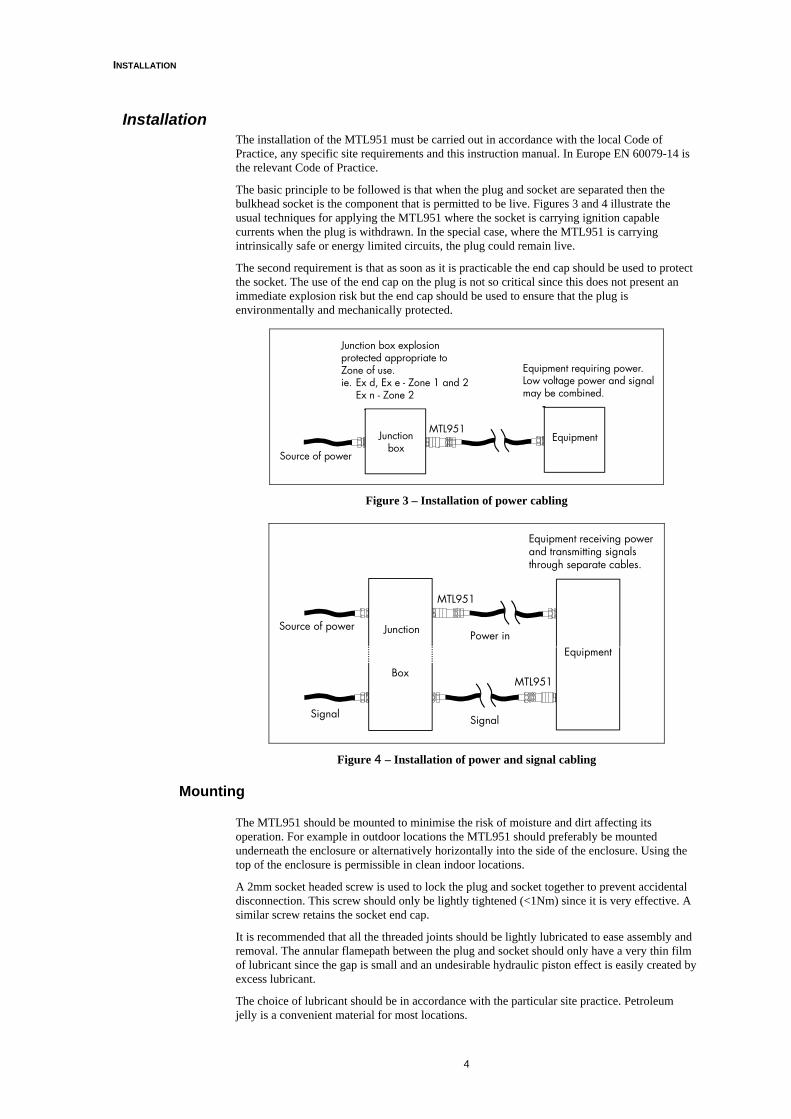
Installation The installation of the MTL951 must be carried out in accordance with the local Code of Practice, any specific site requirements and this instruction manual. In Europe EN 60079-14 is the relevant Code of Practice.
The basic principle to be followed is that when the plug and socket are separated then the bulkhead socket is the component that is permitted to be live. Figures 3 and 4 illustrate the usual techniques for applying the MTL951 where the socket is carrying ignition capable currents when the plug is withdrawn. In the special case, where the MTL951 is carrying intrinsically safe or energy limited circuits, the plug could remain live.
The second requirement is that as soon as it is practicable the end cap should be used to protect the socket. The use of the end cap on the plug is not so critical since this does not present an immediate explosion risk but the end cap should be used to ensure that the plug is environmentally and mechanically protected.
Junctionbox
Source of power
MTL951Equipment
Junction box explosionprotected appropriate toZone of use.ie. Ex d, Ex e - Zone 1 and 2
Ex n - Zone 2
Equipment requiring power.Low voltage power and signalmay be combined.
Figure 3 – Installation of power cabling
Source of power Junction
MTL951
Box
Equipment
MTL951
Signal Signal
Power in
Equipment receiving powerand transmitting signalsthrough separate cables.
Figure 4 – Installation of power and signal cabling
Mounting
The MTL951 should be mounted to minimise the risk of moisture and dirt affecting its operation. For example in outdoor locations the MTL951 should preferably be mounted underneath the enclosure or alternatively horizontally into the side of the enclosure. Using the top of the enclosure is permissible in clean indoor locations.
A 2mm socket headed screw is used to lock the plug and socket together to prevent accidental disconnection. This screw should only be lightly tightened (<1Nm) since it is very effective. A similar screw retains the socket end cap.
It is recommended that all the threaded joints should be lightly lubricated to ease assembly and removal. The annular flamepath between the plug and socket should only have a very thin film of lubricant since the gap is small and an undesirable hydraulic piston effect is easily created by excess lubricant.
The choice of lubricant should be in accordance with the particular site practice. Petroleum jelly is a convenient material for most locations.

INSTALLATION
5
Compatibility requirements of bulkhead mounting socket and enclosure General There are two distinct uses of the MTL951. These are (a) with a flameproof Ex d enclosure, or (b) with an increased safety Ex e or Zone 2 enclosure Ex n.
The first requirement is to choose the correct thread. The thread type is marked on one flat of the hexagon nut. This should be checked before insertion, since the incorrect thread is almost compatible.
When a junction box is used as a distribution unit for power or signals into several sockets, care should be taken that the accessories (such as terminal blocks) are compatible with the certification requirements of the enclosure.
The design of the electrical protection of the installation should ensure that the rating of the sockets is not exceeded. The consequences of the operation of the electrical protection should also be considered interacting particularly in more complex installations such as bus systems.
Earthing and bonding The MTL951 must meet the earthing and bonding requirements for personal safety as well as the explosion proof requirements. The general explosion proof requirements are covered in clauses 6.1 to 6.3 in EN60079-14. The MTL socket has a green and yellow striped lead, which is connected to the outer metalwork of the socket and used for bonding purposes.
Use with a flameproof Ex d enclosure Providing the threads are compatible, the socket will achieve a satisfactory flameproof path with any certified flameproof enclosure. The retaining washer of the socket end cap is held by the socket therefore just before the socket is fully tightened the washer should be positioned so that the retaining chain is conveniently located. Where possible the socket should be positioned so that plug insertion and removal has reasonable access.
The use of a sealing washer to maintain the IP rating of the enclosure is permitted provided that at least five full threads within the enclosure wall are engaged. The MTL951 socket has a generous thread length and the usual test of adequacy of the flamepath is that the end of the socket should be level with or slightly protruding from the enclosure wall.
Light lubrication of the threads during assembly is recommended and the level of ingress integrity without any sealing washer is usually at least IP54.
In almost all circumstances, the socket should be installed with the end cap in place to reduce the possibility of mechanical damage or contamination. The end cap should remain in place until the plug is inserted.
Chain retainingring
Sealing washer(if necessary)
Figure 5 - Detail of bulkhead socket in flameproof enclosure
Note: The earth contact of the power version and the earthy contact of the signal version are positioned so that this connection makes first and breaks last. The earth contact is contact No.1, which is identified on the moulding into which the contact is inserted. The relevant female contact can be readily identified since the hole into which this male contact is plugged is marginally larger than for contacts 2 and 3. The remaining socket connections are numbered clockwise when viewing from the open end.

INSTALLATION
6
The power socket has four leads emerging from it. The two green and yellow leads are both earthy, one is connected to the outer metalwork of the socket and one to the earthy contact of the socket. Both these leads should be connected to the bonding terminal inside the enclosure, which in turn is directly connected to the external bonding connection and the metallic enclosure. The other two leads (brown and blue) are used to connect the supply. In a conventional single phase earthed neutral supply the brown should be used for the live connection and the blue for the neutral. The signal version of the socket also has four leads.
The green and yellow lead is connected to the outer metalwork of the socket. This lead should be connected to the bonding terminal of the enclosure. The white lead is the earthy lead of the signal system and is connected via contact 1. Typically, it would be used as the 0 volts return in a bipolar power supply, the common return conductor of a 3-wire instrumentation system or to terminate the screen of a two-core cable. If the contact is not used then the white lead should be connected to the bonding connection of the enclosure. The red and black leads are connected to contacts 2 and 3 respectively.
The insulation of the socket leads is PVC which is suitable for use at low temperatures but should not be flexed or manipulated below –200C
Use with an increased safety Ex e or Ex n enclosure When used with an Ex e or Ex n enclosure the socket normally requires a half nut inside the enclosure to give adequate stability to the plug and socket combination. A sealing washer is normally used to maintain the IP rating of the enclosure and the enclosure should provide internal and external bonding connections. Where the enclosure is made of non-conducting material an internal plate is used to ensure the effective bonding of the socket. The connection of the leads follows the same pattern as within a flameproof enclosure. The terminals used must be suitable for use within the particular enclosure.
Chain retainingring
Sealing washer(if necessary)
Back nutBonding plate(if plastic enclosure)
Enclosure
Figure 6 - Detail of bulkhead socket in Ex e or Ex n enclosures
Requirements of Cable Gland The gland used with the cable and plug must be compatible with both elements and be Ex d certified since it completes the flameproof enclosure. Guidance on compatibility with the cable is given in IEC 60079 – 14 clause 10.3.
The thread of the cable gland entry into the plug need not be the same as the thread of the socket in the enclosure. Occasionally this facility can be useful as a thread adaptor.
IEC and CENELEC standards use the term “cable entry device” when the word gland would normally be used.
Note: The IEC code of practice IEC 60079-14: 2003 and CENELEC code of practice EN60079-14: 2002 are identical and are published as the same document.
The gland used should be compatible with either the ½” NPT or M20 thread provided on the plug. The type of thread is indicated on one flat of the hexagon adjacent to the thread so that compatibility can readily be checked. Care should be taken because the two threads are not easily distinguished from one another, and a brutal insertion can cause irreparable damage.
It is permissible to use thread adapters if available glands are not compatible but the resultant assembly is not an elegant solution. A flameproof gland is not essential if the plug and socket is

INSTALLATION
7
being used to break an intrinsically safe or non-incendive (low energy) circuit. However, it is usually considered desirable to avoid the possibility of incorrect application. The MTL recommendation is always to use an Ex d gland with a sealing ring, thus avoiding the use of barrier glands and any misunderstanding.
Note: If you wish to explore the reasoning behind this simplification read on. If not ignore the next two paragraphs.
The choice of the Ex d gland is between a conventional gland with a sealing ring, and an epoxy filled barrier gland. The barrier gland was introduced in the 1970’s after some experiments demonstrated that several explosions within an enclosure filled with the ideal hydrogen air mixture resulted in the cable retained by a conventional cable gland being softened by the heat of the explosion. The cable was finally ruptured by the fast rising pressure wave to create a hazard outside the flameproof enclosure. Because of these experiments, the selection procedure proposed by IEC 60079–14 is as illustrated by the selection chart of figure 6. In the particular case of the MTL951 connector, the argument is not straightforward. The initial question is whether the infrequent operation of the plug and socket combination is regarded as an internal source of ignition. Used in the intended fashion it would be operated perhaps ten times a year, for a short period. This is not negligible but arguably sufficiently infrequent to be an acceptable risk. A further factor in arguing that a barrier gland is not necessary is that the volume of gas within the flameproof chamber is very small (less than 25cm3) and hence cannot produce sufficient heat to soften the cable. It is also difficult to imagine a process by which breaking the plug and socket could produce repeated explosions. The selection chart does not consider the case of an extremely small volume enclosure because this situation was not envisaged when the chart was drawn up.
Because of the arguments, MTL consider that it is not necessary to use a barrier gland with an MTL951. If, however, an end user prefers to use a barrier gland, there is no reason why such a gland should not be used. Such use does completely remove any question of the suitability of the gland, but is more expensive and cumbersome.
Yes
Yes
Yes
Yes No
No
No
No
Start
Use a suitableflameproofcable entry
device with asealing ring
Does thisenclosurecontain an
internal sourceof ignition?(see note)
Does thehazardous
gas require IICapparatus?
Is thearea of
installationzone 1
Is thevolume of
the enclosuregreater than
2 dm3 ?
ApplyIEC60079-14Clause 10.3.2
d) or e)
NOTE: Internal sources of ignition include sparks or equipment temperatures occuring in normaloperation which can cause ignition. An enclosure containing terminals only or an indirect entryenclosure (see clause 10.3.1) is considered not to constitute an internal source of ignition.
Figure 7 – Selection chart for cable entry devices into flameproof enclosures for cables complying with IEC 60079-14 clause 10.3.2-item b).

INSTALLATION
8
Requirements of the flexible cable Clause 9 of EN 60079-14 details the requirements of wiring systems for use in hazardous areas and should be read as a whole. In particular clause 9.3.2 and 9.3.3 are relevant to the choice of cable and for convenience are quoted below.
Cable systems for Zones 1 and 2 Cable for fixed apparatus Thermoplastic sheathed cables, thermosetting sheathed cables, elastomeric sheathed cables or mineral insulated metal sheathed cables may be used for fixed wiring.
Cable for portable and transportable apparatus Portable and transportable electrical apparatus shall have cables with a heavy polychloroprene or other equivalent synthetic elastomeric sheath, cables with a heavy tough rubber sheath, or cables having an equally robust construction. The conductors shall have a minimum cross-sectional area of 0.75mm2. If an electrical protective conductor is necessary, it should be separately insulated in a manner similar to the other conductors and should be incorporated within the supply cable sheath.
Portable electrical apparatus with rated voltage not exceeding 250 V to earth and with rated current not exceeding 6 A may have cables with an ordinary polychloroprene or other equivalent synthetic elastomeric sheath, cables with an ordinary tough rubber sheath, or cables having an equally robust construction. These cables are not admissible for portable electrical apparatus exposed to heavy mechanical stresses, for example hand-lamps, foot-switches, and barrel pumps. If, for portable and transportable electrical apparatus, a metallic armour or screen is incorporated in the cable, this shall not be used as the only protective conductor.
Flexible cables Flexible cables in hazardous areas shall be selected from the following:
Ordinary tough rubber sheathed flexible cables;
Ordinary polychloroprene sheathed flexible cables;
Heavy tough rubber sheathed flexible cables;
Heavy polychloroprene sheath;
Plastic insulated cables of equally robust construction to heavy tough rubber sheathed flexible cables.
NOTE: In the absence of IEC cable standards, reference should be made to national or other standards.”
The choice of type of cable is quite wide, and compatibility with the flameproof gland should be ensured. Special care needs to be taken if the cable is required to be flexible at low temperatures. The cable should be positioned so that it is not likely to be mechanically damaged but so that the plug is sufficiently accessible to be removed. The unsupported length of cable needs to be long enough for the plug to be withdrawn but not long enough to apply unacceptable weight or sideways stress on the flameproof gland.
Theoretically, a thread adaptor can be used between the plug and the gland. However, the result is not an elegant solution and should only be used if it is unavoidable.
The choice of crimp contacts used in the plug is determined by the conductor and insulation thickness. The core of the cable can range from 0.75mm2 to 2.5mm2 and is usually stranded but can be solid. The insulation around each core must not exceed 4.3mm in diameter, but this is not usually a problem.
The crimp contacts, which are available for use with the different wire sizes, are indicated in Table 1 below.
MTL part no. Wire size (mm2)
CP951S 0.75 – 1.0
CP951M 1.01 – 1.5
CP951L 1.51 – 2.5
Table 1 - Crimp contact table

INSTALLATION
9
The crimp contacts are available in packs of ten from MTL and it is usually advisable to have spare contacts, in case the crimping process is not perfect at the first attempt.
Plug assembly The assembly of the plug requires that the plug contacts are crimped on to the flexible cable wires. These instructions assume that the recommended crimp tool CT951 is used. If another tool is used then the operator must be sufficiently skilled to ensure that an effective connection is made and the contact is not distorted so that it will not fit into the plug insulator.
The following tools are required:
• Crimp tool CT951(available from MTL) see figure 22 • Allen key M2 • Two open ended spanners 15/16” A/F • NOTE: Ideally the spanners should be 33mm – A/F but these are not always readily
available • Ruler in mm • Tools required to assemble and install the particular cable gland used and to trim the
cable The crimp contacts must be compatible with the cores of the cable used, and before beginning the assembly, this should be checked. (see Table 1)
The use of a suitable lubricant very lightly applied to all threads and mating surfaces is recommended.
The plug assembly procedure is as follows.
Step 1 Check that:
• the necessary tools are available • the cable to be used meets the requirements • the gland is compatible with the cable and the plug • the crimp contacts are available and compatible with the cable cores • the threads and mating surfaces of the plug are clean and undamaged • clear instructions as to which wires are to be finally connected to which plug contact
are available
Step 2 Prepare the cable for the chosen cable gland as per the cable gland manufacturers instructions and fit the gland ensuring adequate length of cable core protrudes from the cable gland (min 75mm)
Step 3 Trim the cables and strip the insulation back so that it protrudes to the length as shown in figure 8 with the gland adaptor fitted.
USERGLAND
GLANDADAPTOR
32.00 +2- 0
8.00+1- 0
Figure 8 - Wire stripping details

INSTALLATION
10
Step 4 Select the locator position on the crimp tool to HND as shown in figure 9 by pulling the spring-loaded locator away from the tool and rotating it.
Figure 9 Crimp tool locator
Crimp tool CT951 covers the majority of wire sizes required. See Table 2 below. In the unlikely event of using a wire size that is not covered by crimp tool CT951 an alternative tool can be used. Contact TYCO ELECTRONICS (AMP) Part No. I-1105553-8
Crimp contact tool
pin hole position.
Usable wire size(mm2)
1 0.75-1.0
1.5 1.2-1.6
2.5 2.1-2.5
Table 2 - Wire sizes
Step 5 The gland adaptor may be temporarily removed at this stage for ease of crimping.
Open the crimp tool fully, insert the selected contact into the appropriate contact hole as indicated in Table 2 and close the tool sufficiently to hold the contact in position.
Step 6 Fully insert the prepared wire into the contact.
Step 7 Squeeze the tool handles together until the ratchet releases. Allow the jaws to open and remove the crimped contact.
Step 8 Check the crimped contact to make sure that the wire is visible through the view port.
< 1.0 mm
View portCable core
Crimp contact
Crimp zone
Figure 10 – Crimping
Locator

INSTALLATION
11
Inspect the cable to ensure no loose cable cores are protruding and that the distance from the crimp skirt to the cable insulation is not greater than 1mm.
Carry out the same procedure for all wire cores.
Step 9 Insert the contacts into the gland adaptor as shown in figure 11 and fully tighten the gland to the adaptor (>40Nm).
Gland adaptor
User gland
Figure 11 – Gland adaptor insertion
Step 10
WARNING: ONCE THE CONTACTS HAVE BEEN ENGAGED IN THE PLUG INSULATOR THEY CANNOT BE REMOVED.
Insert the crimp contacts into the plug insulator being careful to insert each contact into the correct hole as indicated in the following tables below. Ensure that all contacts have been fully engaged.
Gland adaptor
User gland
Plug insulator
Contact orientation
Figure 12 – Plug insulator insertion
Pin No. Usual function Socket wire colour
1 Earth Green/yellow 2 Live Brown 3 Neutral Blue Body bond Green/yellow
Table 3 – Power connector coding

INSTALLATION
12
Pin No. Usual function Socket wire colour
1 Screen White 2 Positive (+ve) Red 3 Negative (-ve) Black Body bond Green/yellow
Table 4 – Signal connector coding
Step11 Ensure that all threads are clean and undamaged before assembly.
Insert the assembly into the plug body and fully tighten, using the two spanners (>40Nm).
Plug body
Plug insulator
User glandGland adaptor
Figure 13 – Final assembly and tightening
Step 12 Check the insulation between the cable and metallic casing. Testing with a 500V Megger is adequate.
Step 13
Optional plug cap (PC951) The optional plug cap provides weatherproof and environmental protection against the ingress of foreign particles to IP65 when the MTL951 hazardous area connector is mounted in the field. In the majority of installations, it should be utilised.
Figure 14 – Plug cap (PC951)

INSTALLATION
13
Cap stowage A cap-retaining clip is provided for the stowage of both the socket cap and plug cap when they are not being used. Fit the cap-retaining clip onto the plug body (see figure 15), and attach chain end ring to the cap-retaining clip fixing screw (see figure 14).
The cap-retaining clip should be aligned and tightened once the plug is connected to the socket, to the most convenient/desired position. Fit the socket cap into the clip. It is recommended that both caps are stowed here to prevent damage to the caps and the junction box.
If the optional plug cap (PC951) is used, fit the plug cap into the socket cap and hand tighten (see figure 16).
Figure 15 Cap retaining clip
Figure 16 Plug and socket cap stowage
Socket assembly This instruction assumes that a socket cap is being used since this is the majority application. A particular installation may require the use of a sealing washer between the socket and the enclosure but this has not been included in these instructions. The use of a suitable lubricant very lightly applied to all threads and mating surfaces is recommended.
The socket assembly procedure is as follows.
Step 1 Check that:
• a suitable 1 5/16” spanner is available • the tools necessary to trim and install the fixed wires to their appropriate locations are
available • the socket thread is compatible with the enclosure thread or the half nut being used • the threads and mating surfaces of the socket and end cap should be inspected to
ensure that they are clean and undamaged • clear instructions as to where and how each of the wires within the enclosure are to be
terminated

INSTALLATION
14
Step 2 Fit the socket cap-retaining ring over the socket receptacle ensuring that the bend on the retaining ring is towards the outside of the enclosure (see figure 17).
Figure 17 – Fitting the socket cap
Step 3 Feed the cables through the appropriate gland hole and screw the socket receptacle into the threaded hole in the Ex d (metal) enclosure (see figure 18) or fit a locking nut when there is an unthreaded hole (see figure 19). If fitting into an Ex e (plastic) enclosure, make sure that there is a good electrical connection between the socket and the earthing plate (see figure 19).
Tighten the socket firmly.
Chain retainingring
Sealing washer(if necessary)
Figure 18 - Enclosure with threaded hole
Chain retainingring
Sealing washer(if necessary)
Back nutBonding plate(if plastic enclosure)
Enclosure
Figure 19 - Enclosure with unthreaded hole

INSTALLATION
15
Step 4 Connect the cables.
Step 5 Screw on the socket cap and lightly tighten (<1Nm) the locking grub screw with a 2mm hexagon key to prevent accidental removal (see figure 20).
Lockinggrubscrew
Figure 20 Locking grub screw

INSPECTION AND MAINTENANCE
16
Operation
Connection Step 1 Examine the plug and socket to ensure that the mating threads and surfaces are clean and undamaged.
Step 2 View the orientation of the male/female locating spigots, bring the plug, and socket together.
Step 3 Rotate the body until engaged.
NOTE: The torque induced by the cable onto the gland/plug body when mated to the socket must be minimised.
Step 4 Hand-tighten the plug collar. This will be approximately 9/10 turns.
Step 5 Lightly tighten the locking grub screw (<1Nm) with a 2mm hexagon key.
Step 6 Screw the two end caps together (if fitted) and store in retaining clip.
Plug collar
Locking grub screw
Figure 21 – Locking screw location
Disconnection Step 1 Unscrew the locking grub screw (2 turns maximum).
Step 2 Unscrew the plug collar (9/10 turns).
Step 3 Remove plug.
Step 4 Protect socket with end cap, and plug if optional cap PC951 is fitted
Step 5 Lock socket end cap in place by lightly tightening the grubscrew.

OPERATION
17
Inspection and Maintenance
Provided that whenever the plug and socket are connected or disconnected the relevant threads and mating surfaces are checked to ensure that they are clean and undamaged, then inspection only requires examination for mechanical damage.
The flexible cable is more vulnerable and should be examined for signs of deterioration at intervals.
The frequency of inspection should be decided for the particular installation taking into account the possibility of mechanical damage, chemical attack, frequency of use and any other factor likely to cause deterioration of the cable
If any attempt to repair damage to the annular flame path between the plug and socket is made the care must be taken not to increase the gap beyond the 0.13mm permitted by the certification.

CRIMP TOOL MAINTENANCE
18
Crimp tool maintenance
Figure 22 – MTL CT951 Crimp tool
Crimp height inspection To check the crimp height, GO – NOGO gauges are required. The relevant diameters are as listed in Table 5.
These gauges are not supplied and should be locally manufactured or purchased.
Select HND on the locator and close the crimp tool handles fully (5 clicks).
Insert the appropriate GO gauge. The gauge must be moveable in the jaws.
It must be impossible to insert the NOGO gauge.
Wire size (mm2)
GO gauge diameter (mm)
NOGO gauge diameter (mm)
1.0 1.85 1.90
1.5 2.15 2.20
2.5 2.35 2.40
Table 5 - GO - NOGO gauges
Crimp height adjustment The crimp tool assembly features a ratchet mechanism and adjustment wheel with a range of settings.
The ratchet mechanism ensures that the tool completes the cycle.
The adjustment wheel controls the operating distance of the tool jaws (before the ratchet opens) thereby controlling the required crimp force.
Although the ratchet is pre-set prior to shipment, it is important that you verify the crimp height. In addition, general use and subsequent wear may cause the tool to go out of adjustment. It is recommended that the crimp height is inspected on a regular basis.
Emergency release wheel
Movable jaw Adjustment wheel
Stationary jaw
CRIMP TOOL MAINTENANCE
19
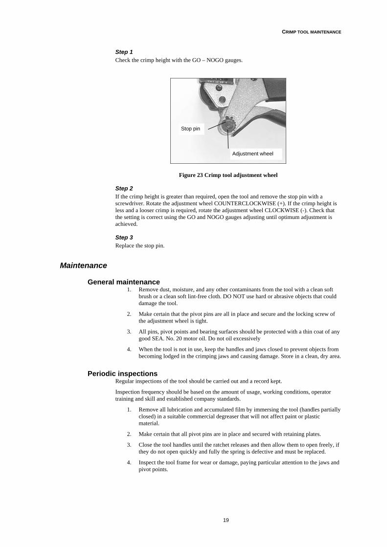
Step 1 Check the crimp height with the GO – NOGO gauges.
Figure 23 Crimp tool adjustment wheel
Step 2 If the crimp height is greater than required, open the tool and remove the stop pin with a screwdriver. Rotate the adjustment wheel COUNTERCLOCKWISE (+). If the crimp height is less and a looser crimp is required, rotate the adjustment wheel CLOCKWISE (-). Check that the setting is correct using the GO and NOGO gauges adjusting until optimum adjustment is achieved.
Step 3 Replace the stop pin.
Maintenance
General maintenance 1. Remove dust, moisture, and any other contaminants from the tool with a clean soft
brush or a clean soft lint-free cloth. DO NOT use hard or abrasive objects that could damage the tool.
2. Make certain that the pivot pins are all in place and secure and the locking screw of the adjustment wheel is tight.
3. All pins, pivot points and bearing surfaces should be protected with a thin coat of any good SEA. No. 20 motor oil. Do not oil excessively
4. When the tool is not in use, keep the handles and jaws closed to prevent objects from becoming lodged in the crimping jaws and causing damage. Store in a clean, dry area.
Periodic inspections Regular inspections of the tool should be carried out and a record kept.
Inspection frequency should be based on the amount of usage, working conditions, operator training and skill and established company standards.
1. Remove all lubrication and accumulated film by immersing the tool (handles partially closed) in a suitable commercial degreaser that will not affect paint or plastic material.
2. Make certain that all pivot pins are in place and secured with retaining plates.
3. Close the tool handles until the ratchet releases and then allow them to open freely, if they do not open quickly and fully the spring is defective and must be replaced.
4. Inspect the tool frame for wear or damage, paying particular attention to the jaws and pivot points.
Adjustment wheel
Stop pin
20
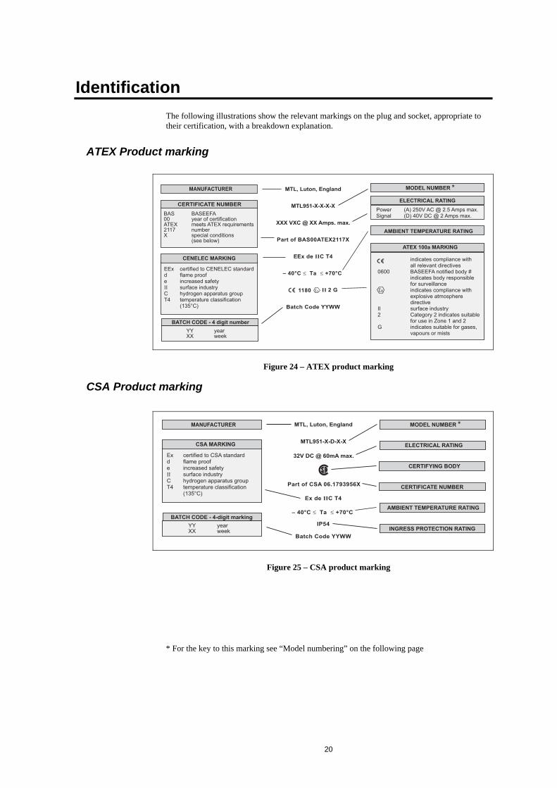
Identification The following illustrations show the relevant markings on the plug and socket, appropriate to their certification, with a breakdown explanation.
ATEX Product marking
!
"#$%&'(% !(
) *+$,$-
./0/$12.
$120$2.. 3412.5
!
" #
1$.6/17
$ !%&'%!!! ! !% (!))*
"+,-%#
. "#,/%01,$1) "2#*/2%0$1
$/1).$2..$/17
$ $.6/17
! ( 3!3
4 !!5!! 3 ! ($ 3(!3
66 ! %)!
7!8 ! )9
3
./$.$/17
$83499%:*
-7;
Figure 24 – ATEX product marking
CSA Product marking
4
<-"4#=%$% !(
!
/)
) *+,$=( <=
$ !%!!! ! !% (!))*
"+,-%#
,$$.6/17
$120$2..
./0/1734
$83499% *>9
/17.,,).3/31.$/17
$/1).$2..$/17
./0/$12.
./$.$/17
3412.5
Figure 25 – CSA product marking
* For the key to this marking see “Model numbering” on the following page

CERTIFICATION
21
Model numbering The following tables give an explanation of how the different types of plugs and sockets are numbered.
Hazardous-area certification Plug Socket
ATEX MTL951 – P – A – M MTL951 – S – A – M
ATEX MTL951 – P – A – N MTL951 – S – A – N
ATEX MTL951 – P – D – M MTL951 – S – D – M
ATEX MTL951 – P – D – N MTL951 – S – D – N
CSA MTL951 – P – D – M – C MTL951 – S – D – M
CSA MTL951 – P – D – N – C MTL951 – S – D – N
Table 6 - Model numbers
Model number key
P - Plug A - Power M - M20 thread C – CSA certified
S - Socket D - Signal N –1/2” NPT thread
Table 7 - Key to Table 6
Special Conditions for Safe Use (extract from BAS00ATEX2117X and CSA 06.1793956X) 1. Only the bulkhead socket may remain energised after separation. The plug must be de-
energised. 2. The bulkhead socket must have the socket cap fitted immediately after separation and
remain fitted at all times, unless the plug and socket is installed within an enclosure affording a minimum degree of protection of IP54.
3. The maximum plug/socket flamepath gap shall not be remachined to exceed 0.13mm 4. The cables permanently attached to the socket shall be suitably terminated and
protected against impact.

CERTIFICATION
22
Ordering information
Ordering code Key for product options: - MTL951-1-2-3-4
Gender type - 1 Power variant - 2 Thread type – 3 Certification type – 4(plugs only)
S = socket for enclosure or bulkhead fixing
P = plug for cable mounting
A = power
D = signal
M = M20
N = ½” NPT
(See Note 1)
none = ATEX cert.
C = CSA cert.
Note 1 -When applied to the socket it relates to enclosure/bulkhead fixing thread. -When applied to the plug it relates to the cable gland mounting thread.
Models available Socket – enclosure/bulkhead mounting (including socket cap)
Product number Description Quantity required
MTL951-S-A-M Socket for power with M20 thread
MTL951-S-A-N Socket for power with 1/2”NPT thread
MTL951-S-D-M Socket for signals with M20 thread
MTL951-S-D-N Socket for signals with 1/2”NPT thread
Plug – cable mounting (plug cap optional - see accessories below) Product number Description Quantity
required
MTL951-P-A-M Plug for power, with thread for M20 gland
MTL951-P-A-N Plug for power, with thread for 1/2” NPT gland
MTL951-P-D-M Plug for signals with thread for M20 gland
MTL951-P-D-N Plug for signals with thread for1/2”NPT gland
MTL951-P-D-M-C Plug for signals with thread for M20 gland – CSA certified
MTL951-P-D-N-C Plug for signals with thread for1/2”NPT gland – CSA certified
Crimp contacts for plug (see Note 2) Product number
Description Quantity required
CP951S Crimp plug contact for wire size 0.75-1.0mm2 (pack of 10)
CP951M Crimp plug contact for wire size 1.01-1.5mm2 (pack of 10)
CP951L Crimp plug contact for wire size 1.51-2.5mm2 (pack of 10)
Note 2:- The crimp contacts are not fitted in the plug. When ordering, 3 crimp contacts per plug are required.
Accessories Product number
Description Quantity required
PC951 Optional plug cap (protects against ingress of water and dirt)
CT951 Crimp tool for plug contacts

ORDERING INFORMATION
23
Certification
ATEX certification The following is a reproduction of ATEX certificate BAS00ATEX2117X

CERTIFICATION
24
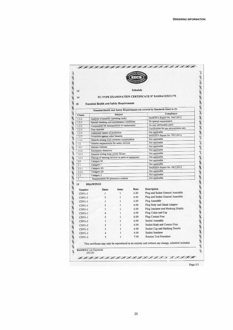
ORDERING INFORMATION
25

APPENDIX A
26
Appendix A
SPECIFICATION
Electrical Voltage and current rating
MTL951-P-A-x (power) 110/230V AC, 50/60Hz, 2.5Amps MTL951-P-D-x (signal) 40V DC, 2 Amps (ATEX version) MTL951-P-A-x-C (signal) 32V DC, 60 mA (CSA version)
Contact number Power 3 Signal 3
Contact resistance < 3 mΩ
Main cable size and connection 0.8 to 2.5mm2 - crimped receptacles
'Flying' leads 1.0mm2 (17AWG) rated at 300V to BS6231 Length – 1 metre
Mechanical Body Material
Brass Contact Material
Gold Plated Phosphor Bronze Gaskets and seals
Neoprene/Silicone Weight
Socket 185gm Socket with cap 290gm Plug 332gm Plug with cap 462gm
Electrical Entry 1/2" 14-NPT Female or M20 x 1.5 Female
Instrument / Junction box connection 1/2" 14-NPT Male or M20 x 1.5 Male
Environmental Weather Protection
IP54 Operating and storage temperature
–40°C to +70°C. Humidity
5 to 95% non-condensing Vibration
To BS 2011 30 to 500 Hz To BS EN 60068 10 to 500 Hz
Shock To BS EN 60068 50g
Reliability > 500 operations

APPENDIX A
27
Certification BASEEFA
BAS00ATEX2117X
II 2 G
EEx de IIC T4
–40º C ≤ Tamb ≤ +70º C
CSA
06.1793956X
Ex de IIC T4
–40º C ≤ Tamb ≤ +70º C
IP54
UK Patent No.
GB 2 355 348
Dimensions (mm)
!
"
#$ %& & %' % &
Figure 26 - MTL951 dimensions
Pin allocations
Power versionPin 1 EarthPin 2 LivePin 3 Neutral
Signal versionPin 1 ScreenPin 2 PositivePin 3 Negative
Viewed from rear of plugand
open end of socket NOTE:‘Keyed’ to preventcross connections
Figure 27 – pinout of plug and socket

28

29

Group Internet home page http://www.mtl-inst.com/
Members of The MTL Instruments Group
MTL Instruments Pty Limited1/30 Canvale RoadCanning ValePerth, WA 6155AustraliaTel: +61 (0)8 9455 2994 Fax: +61 (0)8 9455 2805E-mail: [email protected]
MTL Canada Safety Instrumentation#102, 4249 97 StreetEdmonton, AlbertaCanada T6E 5Y7Tel: +1 780 485 3132 Fax: +1 780 485 3122E-mail: [email protected]
MTL Instruments PteRoom 1002A, The GatewayNo 10 Yabao Road, Chaoyang DistrictBeijing 100020ChinaTel: +86 010 8562 5718/5720/5721 Fax: +86 010 8562 5725E-mail: [email protected]
MTL Instruments sarlLes Carrés du Parc10 rue des Rosiéristes69410 Champagne au Mont d’Or FranceTel: +33 (0)4 78 64 98 32 Fax: +33 (0)4 78 35 79 41E-mail: [email protected]
MTL Instruments GmbHAn der Gümpgesbrücke 17D-41564 KaarstGermanyTel: +49 (0)2131 718930 Fax: +49 (0)2131 7189333E-mail: [email protected]
MTL India Pvt. LimitedNo. 36, Nehru StreetOff Old Mahabalipuram RoadSholinganallurChennai - 600 119IndiaTel: + 91 (0)44 24501660/24501857 Fax: + 91 (0)44 24501463E-mail: [email protected]
MTL Italia srlVia Cantù 11I - 20092 Cinisello Balsamo MIItalyTel: +39 (0)2 61802011 Fax: +39 (0)2 61294560E-mail: [email protected]
MTL Instruments KK3rd Floor, Gotanda Masujima Building1-8-13 Higashi-Gotanda, Shinagawa-KuTokyo 141-0022JapanTel: +81 (0)3 5420 1281 Fax: +81 (0)3 5420 2405E-mail: [email protected]
MTL Instruments BVde Houtakker 36, 6681 CW BemmelThe NetherlandsTel: +31 (0)481 450250 Fax: +31 (0)481 450260E-mail: [email protected]
MTL Instruments Pte Limited31 Ubi Road 1#04-01 Aztech BuildingSingapore 408694Tel: +65 6 487 7887 Fax: +65 6 487 7997E-mail: [email protected]
MTL InstrumentsVilla No. 4, Sector 2-17,Street 6PO Box 53234, Abu Dhabi, UAETel: +971 2 446 6840 Fax: +971 2 446 6841E-mail: [email protected]
MTL Instruments LimitedPower Court, Luton, BedfordshireEngland LU1 3JJTel: +44 (0)1582 723633 Fax: +44 (0)1582 422283E-mail: [email protected]
MTL Incorporated9 Merrill Industrial Drive, Hampton NH 03842USATel: +1 800 835 7075 Fax: +1 603 926 1899E-mail: [email protected]