Hawko Zhaga Systems Installation Instructions
30
Hawko Zhaga Systems Installation Instructions
Transcript of Hawko Zhaga Systems Installation Instructions

Hawko Zhaga SystemsInstallation Instructions


Contents
Wire Suspension Installation 4
Recessed Brackets 6
Fixed Suspension Rods 8
Swivel Suspension Rods 10
Surface Mount Ceiling 12
Surface Mount Wall 13
Slider Lock Barrels 14
Self Leveling Barrels 16
Remote Gear 18
Joining Clasp 19
Joining Plate In Back Channel 20
Back Spine 21
Terminal Block 22
Remove LED Tray 23
(Aluminimum Block)
Remove LED Tray (Hinged) 24
Replace LED Board 25
Replace Resistor 26
Flex Wiring 27
Removing End-caps 28
4
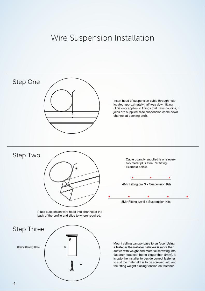
Wire Suspension Installation
Step Two
Step Three
→
Place suspension wire head into channel at the back of the profile and slide to where required.
Cable quantity supplied is one every two meter plus One Per fitting.Example below.
4Mtr Fitting c/w 3 x Suspension Kits
8Mtr Fitting c/w 5 x Suspension Kits
Mount ceiling canopy base to surface (Using a fastener the installer believes is more than suffice with weight and material screwing into, fastener head can be no bigger than 8mm). It is upto the installer to decide correct fastener to suit the material it is to be screwed into and the fitting weight placing tension on fastener.→
Step One
Insert head of suspension cable through hole located approximately half-way down fitting (This only applies to fittings that have no joins, if joins are supplied slide suspension cable down channel at opening end).
Ceiling Canopy Base
5
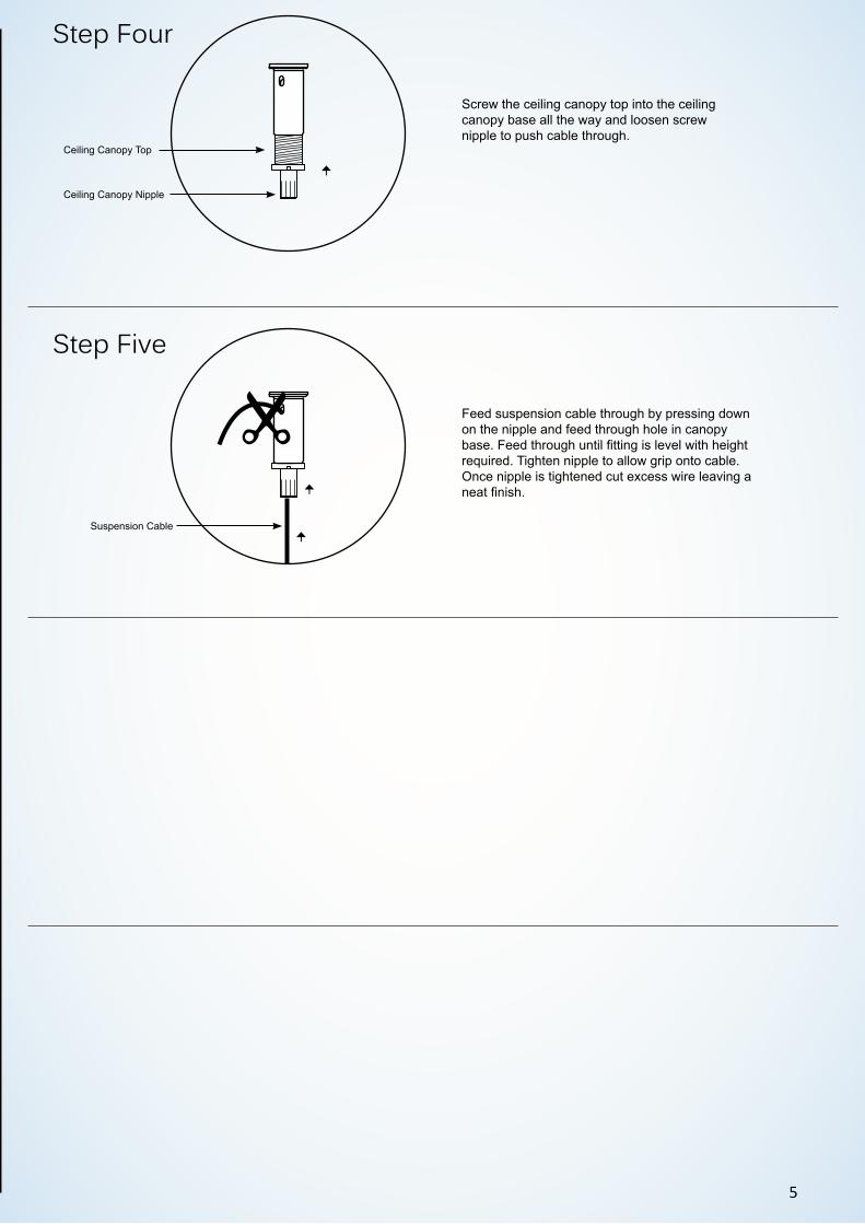
Step Four
Step Five
Screw the ceiling canopy top into the ceiling canopy base all the way and loosen screw nipple to push cable through.
Feed suspension cable through by pressing down on the nipple and feed through hole in canopy base. Feed through until fitting is level with height required. Tighten nipple to allow grip onto cable. Once nipple is tightened cut excess wire leaving a neat finish.
→→
→
Ceiling Canopy Top
Ceiling Canopy Nipple
Suspension Cable

6
Step Two
Step Three
Step One
Recessed Brackets
Insert bolt supplied into the pre-drilled holes.
Bracket quantity supplied is one every two meter plus one per fitting.Example below.
4Mtr Fitting c/w 3 x Recessed Bracket kits
8Mtr Fitting c/w 5 x Recessed Bracket kits
Remove diffuser by pulling the clear plastic sleeve hanging out sides of diffuser or by Levering the end of diffuser by using a small flat head screwdriver.
Using a philips head screw driver locate and remove all four screw holding LED board tray in place to allow access underneath. If necessary disconnect white & black wires for full removal of tray.
Note. white cable positive black cable negative
Screw bolt into bracket with bracket wings surrounding light fitting.
Recessed Bracket

7
Step Four
Step Five
Step Six
Squeeze sides of bracket and push fitting through cut-out in Ceiling.
→
→ → 60 Recessed Cut-Out: 70mm (W) x Length Provided On Order Plus 10mm (L)100 Recessed Cut-Out:100mm (W) x Length Provided On Order Plus 10mm (L)
Once bracket has spread inside ceiling use a 5/8 socket to tighten bolt. This will spread bracket locking fitting into place.
Ceiling
Ceiling
→Re-install LED tray by screwing fasteners removed back into where removed from. Reconnect cable in correct place making sure not to mix positive and negative wiring (it will void LED boards if wired wrong) and clip diffuser back into place.
Note. white cable positive black cable negative

8
Fixed Suspension Rods
Step Two
Step Three
Step One
Fix four fasteners through the 6mm holes in base plate to the ceiling (Using a fastener the installer believes is more than sufficient with weight and material screwing into). Check location of pre-drilled holes in back of fitting before mounting plate to ceiling.
Ceiling
Base PlateBase Plate
Screw rod into base plate until thread is hidden (Rod Length Max 4Mtrs).
Screw base plate cover to base plate.
Suspension Rod
Cover Plate
Remove diffuser by pulling the clear plastic sleeve hanging out sides of diffuser or by Levering the end of diffuser by using a small flat head screwdriver.
Using a philips head screw driver locate and remove all four screw holding LED board tray in place to allow access underneath. If necessary disconnect white & black wires for full removal of tray.
Note. white cable positive black cable negative

9
Step Four
Step Five
→
Push fitting up so that rods go through corresponding holes.
Once rod inside fitting, screw nut provided onto rod finger tight. Feed power cable down rod closest to terminal block to achieve hidden cable feed.
→Re-install LED tray by screwing fasteners removed back into where removed from. Reconnect cable in correct place making sure not to mix positive and negative wiring (it will void LED boards if wired wrong) and clip diffuser back into place.
Note. white cable positive black cable negative
Step Six

10
Swivel Suspension Rods
Step Two
Step Three
Step One
Mark out where the suspension rods need to be installed and put the base plate inner, swivel nut and outer base plate together. Please note direction that all three components are faced. The swivel nut will sit in between the inner and outer parts of the base plate.
Once the inner base plate, outer base plate and swivel nut are together line up the holes of the inner and outer base plate parts. Install appro-priate fasteners for the weight and material fixing into at the locations previously marked out. Do not completely tighten fasteners to allow swivel in rods to adjust when fitting is installed.
Swivel Nut
Outer Base Plate
Inner Base Plate
Fasteners
Remove diffuser by pulling the clear plastic sleeve hanging out sides of diffuser or by Levering the end of diffuser by using a small flat head screwdriver.
Using a philips head screw driver locate and remove all four screw holding LED board tray in place to allow access underneath. If necessary disconnect white & black wires for full removal of tray.
Note. white cable positive black cable negative

11
Step Four
Step Five
Step Six
→Push fitting up so that rods go through corresponding holes.
Once rod inside fitting, screw nut provided onto rod finger tight. Feed power cable down rod closest to terminal block to achieve hidden cable feed.
Before going any further make sure that the cover plate is around the rod.
Once the rods are at the correct angle required tighten fasteners and screw cover plate to base plate outer.
Note maximum swivel is 20 Degrees.
Suspension Rod
Cover Plate
Suspension Rod Nut
→
Re-install LED tray by screwing fasteners removed back into where removed from. Reconnect cable in correct place making sure not to mix positive and negative wiring (it will void LED boards if wired wrong) and clip diffuser back into place.
Note. white cable positive black cable negative
Step Seven

12
Surface Mount Ceiling
Remove diffuser by pulling the clear plastic sleeve hanging out sides of diffuser or by levering the end of diffuser by using a small flat head screwdriver.
Using a Philip head screw driver locate and remove all four screw holding tray in place to allow access underneath. If necessary discon-nect white & black wires for full removal of tray.
Note. white cable positive black cable negative
Step Two
Step Three
Step One 5
00
500
5
00
Drill fasteners through the 4.5mm holes provided approximately every 500mm apart. If no ‘pre-drilled’ holes specified Hawko recommend using fasteners every 500mm when mounting to ceiling or wall.
13
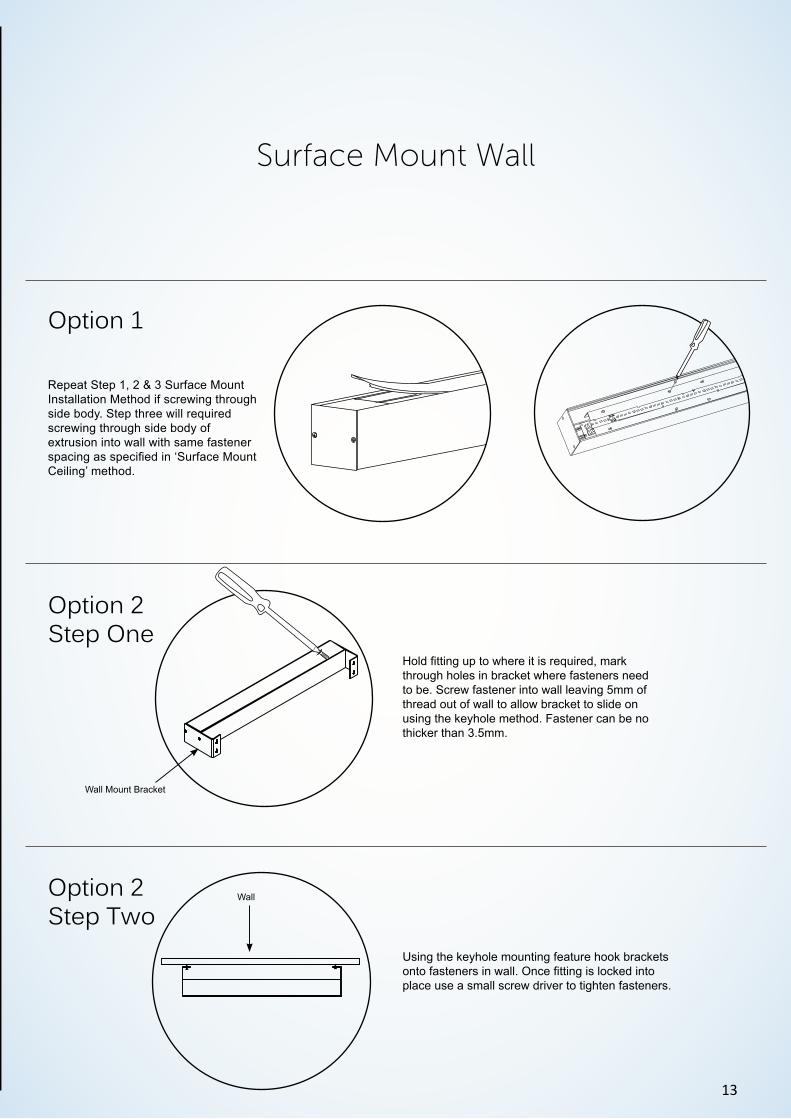
Repeat Step 1, 2 & 3 Surface Mount Installation Method if screwing through side body. Step three will required screwing through side body of extrusion into wall with same fastener spacing as specified in ‘Surface Mount Ceiling’ method.
Option 2Step One
Option 2Step Two
Surface Mount Wall
Hold fitting up to where it is required, mark through holes in bracket where fasteners need to be. Screw fastener into wall leaving 5mm of thread out of wall to allow bracket to slide on using the keyhole method. Fastener can be no thicker than 3.5mm.
Using the keyhole mounting feature hook brackets onto fasteners in wall. Once fitting is locked into place use a small screw driver to tighten fasteners.
Option 1
Wall Mount Bracket
Wall

14
Slider Lock Barrels
Step Three
Step One
Step Two
Mount base of ceiling canopy to surface using a self-tapered screw. Screw head can be no bigger than 8mm. It is up to the installer to decide on correct fastener to suit the material it is to be screwed into and the fitting weight placing tension on fastener.→
Screw the ceiling canopy top into the ceiling canopy base with suspension cable head inside ceiling canopy base allow canopy to hold cable.
→→
Insert head of locking barrel through hole located approximately half-way down fitting (This only applies to fittings that have no joins, if joins are supplied slide suspension cable down channel at opening end).
Ceiling Canopy Top
Ceiling Canopy Nipple
Ceiling Canopy Base
Suspension Cable
Slider Barrel

15
Step Four
Step Five
Step Six
Use 2mm allen key to loosen grub screw inside locking barrel.
Feed cable through locking barrel till height required is achieved
Use 2mm allen key to tighten grub screw enough to hold weight being careful not to pierce through cable making it weak.
Cut any excess cable to create a neat finish.

16
Self Leveling Barrels
Step Two
Mount base of ceiling canopy to surface us-ing a self-tapered screw. Screw head can be no bigger than 8mm. It is up to the installer to decide on correct fastener to suit the material it is to be screwed into and the fitting weight placing tension on fastener.→
Step One
Screw the ceiling canopy top into the ceiling canopy base with suspension cable head inside ceiling canopy base allow canopy to hold cable.
→→
Ceiling Canopy Top
Ceiling Canopy Nipple
Ceiling Canopy Base
Suspension Cable
Step Three
Insert head of suspension cable through hole located approximately half-way down fitting (This only applies to fittings that have no joins, if joins are supplied slide suspension cable down channel at opening end).

17
Step Four
Step Five
→
Feed suspension cable through until at height required then tighten nipple at end of self-leveling barrel. Once at height tighten bolt at bottom of barrel to lock wire into place. Cut off excess wire poking through hole in side of barrel.
Remove bolt at bottom of self-leveling barrel, slide the wire between the channel where bolt was removed then screw bolt 3/4 of the way.
Self Leveling Barrel
Self Leveling Barrel Nipple
Suspension Cable

18
Remote Gear
Remove diffuser by levering the end of diffuser with a small flat head screwdriver. Wire terminal block as per terminal wiring instructions (page 21).
Place one side of diffuser into place and push to clip other side into place.
Step Two
Step OneInstall fitting as required and place remote box inside wall or ceiling cavity. Plug EasConnect male and female connectors together to get power from remote box to fitting.
Plasterboard
Ceiling Trimmer
Remote Gear
Ceiling CanopyConnectors

19
Step Two
Step One
Joining Clasp
Step Three
Remove diffuser or infill and LED tray to get access to joining clasp on the male end. Slide joining rods into their corresponding holes in extrusion.
Clasp Male End
Push down on clasp lever to lock into place.
If there is a gap or to much tensions and will not lock-in, turn triangle shape head of male end clockwise or anti-clockwise depending if pulling in or easing tension is required.
→Joining Rods
20
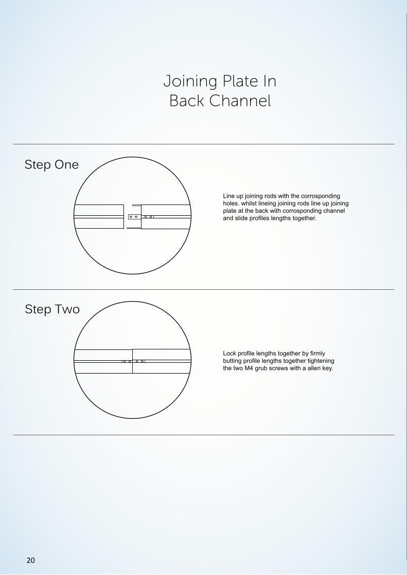
Step Two
Step One
Joining Plate In Back Channel
Lock profile lengths together by firmly butting profile lengths together tightening the two M4 grub screws with a allen key.
Line up joining rods with the corrosponding holes. whilst lineing joining rods line up joining plate at the back with corrosponding channel and slide profiles lengths together.

21
Back Spine
Step Two
Step One
Remove the fasteners where side-body is not attached to back-spine. Slide extrusion together making sure side-body and back-spine is flush with each other and joining rods are in correct position.
Tighten the fasteners that were removed back into where they were removed from to connect fitting joins together.
Side Body
Back Spine
Side Body
Currently available in our 70 Rectangle & 100 Rectangle only

22
Terminal Block
L
N
Non Dim
L
N
DIM L
DIM N
Dimmable
L
N
DIM L
DIM N
Non Dim - Unswitched Live
Brown - Live
Blue - Neutral
Green/Yellow - Earth
Brown - Live
Blue - Neutral
Green/Yellow - EarthBrown - Live
Blue - Neutral
Green/Yellow - Earth
Red - Neutral
White -Live
Brown - LiveBlue - Neutral
Green/Yellow - Earth
Black - Dimming NeutralWhite - Dimming Live
Brown - Live
Blue - Neutral
Green/Yellow - Earth
White - Unswitched LiveWhite - Unswitched Live
Green/Yellow - Earth
Brown - LiveBlue - Neutral

23
Remove LED Tray(Aluminimum Block)
Remove diffuser by pulling the clear plastic sleeve hanging out sides of diffuser or by levering the end of diffuser by using a small flat head screwdriver.
Step Three
Step One
Remove the four philips head screws to remove LED board tray and gain access underneath LED tray.
Remember where removed fasteners from place new tray in place and screw the fasteners removed back into location removed from. Push cables into LED board tabs making sure positive and negative are in correct place and push clip into place. Place one side of diffuser into place and push to clip other side into place.
Note. white cable positive black cable negative
Step TwoUsing a small screw driver push down on the LED board cable terminals tab keeping the cables in. When pressure is applied to the tabs pull cables out to release cable.
Note. white cable positive black cable negative
Board Cable Terminal

24
Remove LED Tray (Hinged)
Remove diffuser by pulling the clear plastic sleeve hanging out sides of diffuser or by levering the end of diffuser by using small flat head screwdriver.
Step One
Unscrew Fasteners located in the one side of tray (fasteners spacings and amount will change depending on tray size).
Step Two→
Step Three
→
→ →
→
Squeeze sides of profile to release clipped in side of tray from wall of profile (the side of tray released is the side that was screwed in).
Once side of tray is released from profile the tray is able to hang without assistance by hinge design.
Push tray back into place by applying pressure to trays clip in system in the side of profile. Once clipped-in screw fasteners taken out back into holes where came from.
Once tray is installed correctly place one side of diffuser into place and push to clip other side in.
→

25
Replace LED Board
Remove diffuser by pulling the clear plastic sleeve hanging out sides of diffuser or by levering the end of diffuser by using a small flat head screwdriver.
Step Two
Step One
Get a flat head screw driver and lever the button head fastener out. Once center pins are removed lever board/s from tray.
→
Board Cable Terminal
Using a small screw driver push down on the LED board cable terminals tab keeping the cables in. When pressure is applied to the tabs pull cables out to release cable.
Note. white cable positive black cable negative
→
Push the button head fasteners back in where removed from. Reconnect cable in correct place making sure not to mix positive and negative wiring (it will void LED boards if wired wrong) and place one side of diffuser into place and push to clip other side into place.
Note. white cable positive black cable negative
Step Three

26
Replace Resistor
1
2
3
LN
PHILIPS1234567
LED+LED+LED-LED-NTCRSET2SGND
Resistor
Step Two
Step One
Using a small pointed object to push down into hole which lines up with the resistor legs. At the same time as push down to release clamp. Pull the corresponding resistor leg to remove from driver.
Push both legs of new resistor in the holes where the old resistor came from. Putting the resistor legs in either hole will not affect resistor.

27
Flex Wiring
Brown - Live
Green/Yellow - Earth
Blue - Neutral
Brown - Live
Blue - Neutral
Brown - Live White - Unswitched Live
Green/Yellow - Earth
Red - Positive
White - Negative
Blue - Neutral Green/Yellow - Earth

28
Use a phillips-head screw driver to remove end-cap.
Use a 7mm shifter to remove nut. Once nut is removed end-cap will release from body.
Remove diffuser by pulling the clear plastic sleeve hanging out sides of dif-fuser or by levering the end of diffuser by using paint Tin Opener.
When finished place one side of diffus-er into place and push to clip other side into place.
Standard End-cap
Screwless End-cap
Removing End-caps
29

ContactPh: (07) 5491 5800FAX: (07) 5491 5984
E-mail: [email protected]: www.hawko.com.au
Address: 5 Development Ct,Caloundra Queensland 4551