New IP20 Industrial Ethernet Connector Standard from HARTING

HARTING Industrial Connectors Han®

Contents Chapter
Industrial Connectors | Technical characteristics .................................... 00
Han A® | Slim Construction Size (up to 16 amperes) ............................. 01
Han D® / DD® | up to 216 contacts ....................................................... 02
Han E® / Han® ES/ESS/EE/EEE | for 16 amperes ............................... 03
Han Hv E® / Han® Hv ES | for higher voltages ..................................... 04
Han-Com® | Combination Connectors ................................................... 05
Han-Modular® | modular connectors ...................................................... 06
Han® HsB | for higher currents .............................................................. 07
Han® AV | Terminal Block Connectors ................................................... 08
Staf® | for low voltages ........................................................................... 09
Han-Snap® | for the use in switch cabinets ............................................ 11
Han-Port® | Interface for power and signals .......................................... 12
Han® Q | compact connectors ............................................................... 13
Han® HC-Modular/Individual | High Current Connectors ....................... 14
Han-Power® | Energy Bus Components ................................................ 15
Han® HMC | for High Mating Cycles ...................................................... 16
Han® High Temp | for high temperatures ............................................... 17
Han-Brid® | Industrial Bus Interface ....................................................... 19
Han® PCB termination ........................................................................... 20
Han-Yellock® .......................................................................................... 25
Han-Eco® ............................................................................................... 29
Han® Hoods and Housings | with metric thread ..................................... 31
Han® Thermocouple .............................................................................. 41
Han® GND ............................................................................................. 42
Accessories ............................................................................................ 80
Tools ....................................................................................................... 90
Industrial Connectors – Overview of the series

Industrial Connectors Han®
Economicand ReliableConnections
SpecificationsDIN EN 60 664-1 (VDE 0110-1)
Principles, requirements and tests
DIN EN 61 984 (VDE 0627) Connectors, Safety requirements and tests
Note: The connectors included in this ca-talogue should not be coupled or de-coupled under electrical load unless otherwise stated.The connector must not be powered-up in the un-mated condition. This is also true if the connector is closed with a protection cover, unless other-wise stated.The provision of protection against electric shock is the responsibility of the user. Protection can be achieved by the use of HARTING hoods and housings coupled with/or alternatively appropriate installation methods provi-ded by the user.The female connector in a HARTING hood or housing offers finger safe protection according to relevant stan-dards for the mating face, even in the unmated condition, unless otherwise stated.Connectors of the same or different series being mounted side by side may be protected against incorrect mating by the use of coding options.
StandardDIN EN 175 301-801
ApprovalsUL File No. E 23 50 76 (www.ul.com)CSA File No. LR 18 753, SEV for insertsGL certificate No. 13 674 - 99 HH
For "non standard applications" we can manufacture designs to match your requirements.Please discuss requirements with us.
HARTING components help you to construct top quality products – economically and in line with market requirements.
Certified according to EN ISO 9001in design/development, production,
installation and servicing
Terminations• Screw terminal• Crimp terminal• Cage-clamp terminal• Wrap terminal• Solder terminal• Axial-screw terminal• Rapid terminal• IDC termination
Inserts• Leading protective ground• Polarised for correct mating• Interchangeability of male and female
inserts in hoods and housings• Captive fixing screws• Can be used with hoods and housings,
or for rack and panel applications
Hoods/Housings• Standard Hoods/Housings• Hoods/Housings for harsh environ-
mental requirements• Hoods/Housings for intrinsically safe
plant• Degree of protection IP 65• Electrical connection with protective
ground• High mechanical strength and vibration-
resistance ensured by locking levers• Spring-loaded coversin shockproof thermoplastic or metalcovers, both lockable
Accessories• Extensive range of cable protection
and sealing accessories• Protective covers available• Coding options for incorrect mating
protection
General information
It is the customer's responsibility to check whether the components illus-trated in this catalogue also comply with different regulations from those stated in special fields of applications.
We reserve the right to modify de-signs or substance of content in or-der to improve quality, keep pace with technological advancement or meet particular requirements in production.
No part of this catalogue may be reproduced in any form (print, photocopy, microfilm or any other process) or processed, duplicated or distributed by means of electronic systems without the prior written consent of HARTING Electric GmbH & Co. KG, Espelkamp. We are bound by the German version only.
© HARTING Electric GmbH & Co. KG, Espelkamp – All rights reserved, including those of the translation.

Transforming customer wishes into concrete solutions
The HARTING Technology Group is skilled in the fields of electrical, electronic and optical
connection, transmission and networking, as well as in manufacturing, mechatronics and
software creation. The Group uses these skills to develop customized solutions and products
such as connectors for energy and data transmission applications including, for example,
mechanical engineering, rail technology, wind energy plants, factory automation and the
telecommunications sector. In addition, HARTING also produces electro-magnetic components
for the automobile industry and offers solutions in the field of Enclosures and Shop Systems.
The HARTING Group currently comprises 51 sales companies and production plants worldwide
employing a total of about 4,200 staff.
H A R T I N G w o r l d w i d e
HARTING RepresentativesHARTING Subsidiary company
We aspire to top performance.Connectors ensure functionality. As core elements
of electrical and optical wiring, connection and
infrastructure technologies, they are essential in
enabling the modular construction of devices, machines
and systems across a very wide range of industrial
applications. Their reliability is a crucial factor
guaranteeing smooth functioning in the manufacturing
area, in telecommunications, applications in medical
technology – in fact, connectors are at work in virtually
every conceivable application area. Thanks to the
consistent further development of our technologies,
customers enjoy investment security and benefit from
durable, long term functionality.
Always at hand, wherever our customers may be.Increasing industrialization is creating growing
markets characterized by widely diverging demands and
requirements. The search for perfection, increasingly
efficient processes and reliable technologies is a common
factor in all sectors across the globe.
HARTING is providing these technologies – in Europe,
America and Asia. The HARTING professionals at our
international subsidiaries engage in close, partnership
based interaction with our customers, right from the very
early product development phases, in order to realize
customer demands and requirements in the best possible
manner.
Our people on location form the interface to the centrally
coordinated development and production departments.
In this way, our customers can rely on consistently high,
superior product quality – worldwide.
Our claim: pushing performance.HARTING provides more than optimally attuned
components. In order to serve our customers with the best
possible solutions, HARTING is able to contribute a great
deal more and play a closely integrative role in the value
creation process.
From ready assembled cables through to control racks
or ready-to-go control desks: Our aim is to generate
the maximum benefits for our customers – without
compromise!
Quality creates reliability – and warrants trust.The HARTING brand stands for superior quality and
reliability – worldwide. The standards we set are the
result of consistent, stringent quality management that is
subject to regular certifications and audits.
EN ISO 9001, the EU Eco-Audit and ISO 14001 are key
elements here. We take a proactive stance towards new
requirements, which is why HARTING is the first company
worldwide to have obtained the IRIS quality certificate for
rail vehicles.

Transforming customer wishesinto concrete solutions
The HARTING Technology Group is skilled in the fields of electrical, electronic and optical
connection, transmission and networking, as well as in manufacturing, mechatronics and
software creation. The Group uses these skills to develop customized solutions and products
such as connectors for energy and data transmission applications including, for example,
mechanical engineering, rail technology, wind energy plants, factory automation and the
telecommunications sector. In addition, HARTING also produces electro-magnetic components
for the automobile industry and offers solutions in the field of Enclosures and Shop Systems.
The HARTING Group currently comprises 51 sales companies and production plants worldwide
employing a total of about 4,200 staff.
H A R T I N G w o r l d w i d e
HARTING RepresentativesHARTING Subsidiary company
We aspire to top performance.Connectors ensure functionality. As core elements
of electrical and optical wiring, connection and
infrastructure technologies, they are essential in
enabling the modular construction of devices, machines
and systems across a very wide range of industrial
applications. Their reliability is a crucial factor
guaranteeing smooth functioning in the manufacturing
area, in telecommunications, applications in medical
technology – in fact, connectors are at work in virtually
every conceivable application area. Thanks to the
consistent further development of our technologies,
customers enjoy investment security and benefit from
durable, long term functionality.
Always at hand, wherever our customers may be.Increasing industrialization is creating growing
markets characterized by widely diverging demands and
requirements. The search for perfection, increasingly
efficient processes and reliable technologies is a common
factor in all sectors across the globe.
HARTING is providing these technologies – in Europe,
America and Asia. The HARTING professionals at our
international subsidiaries engage in close, partnership
based interaction with our customers, right from the very
early product development phases, in order to realize
customer demands and requirements in the best possible
manner.
Our people on location form the interface to the centrally
coordinated development and production departments.
In this way, our customers can rely on consistently high,
superior product quality – worldwide.
Our claim: pushing performance.HARTING provides more than optimally attuned
components. In order to serve our customers with the best
possible solutions, HARTING is able to contribute a great
deal more and play a closely integrative role in the value
creation process.
From ready assembled cables through to control racks
or ready-to-go control desks: Our aim is to generate
the maximum benefits for our customers – without
compromise!
Quality creates reliability – and warrants trust.The HARTING brand stands for superior quality and
reliability – worldwide. The standards we set are the
result of consistent, stringent quality management that is
subject to regular certifications and audits.
EN ISO 9001, the EU Eco-Audit and ISO 14001 are key
elements here. We take a proactive stance towards new
requirements, which is why HARTING is the first company
worldwide to have obtained the IRIS quality certificate for
rail vehicles.
H A R T I N G w o r l d w i d e
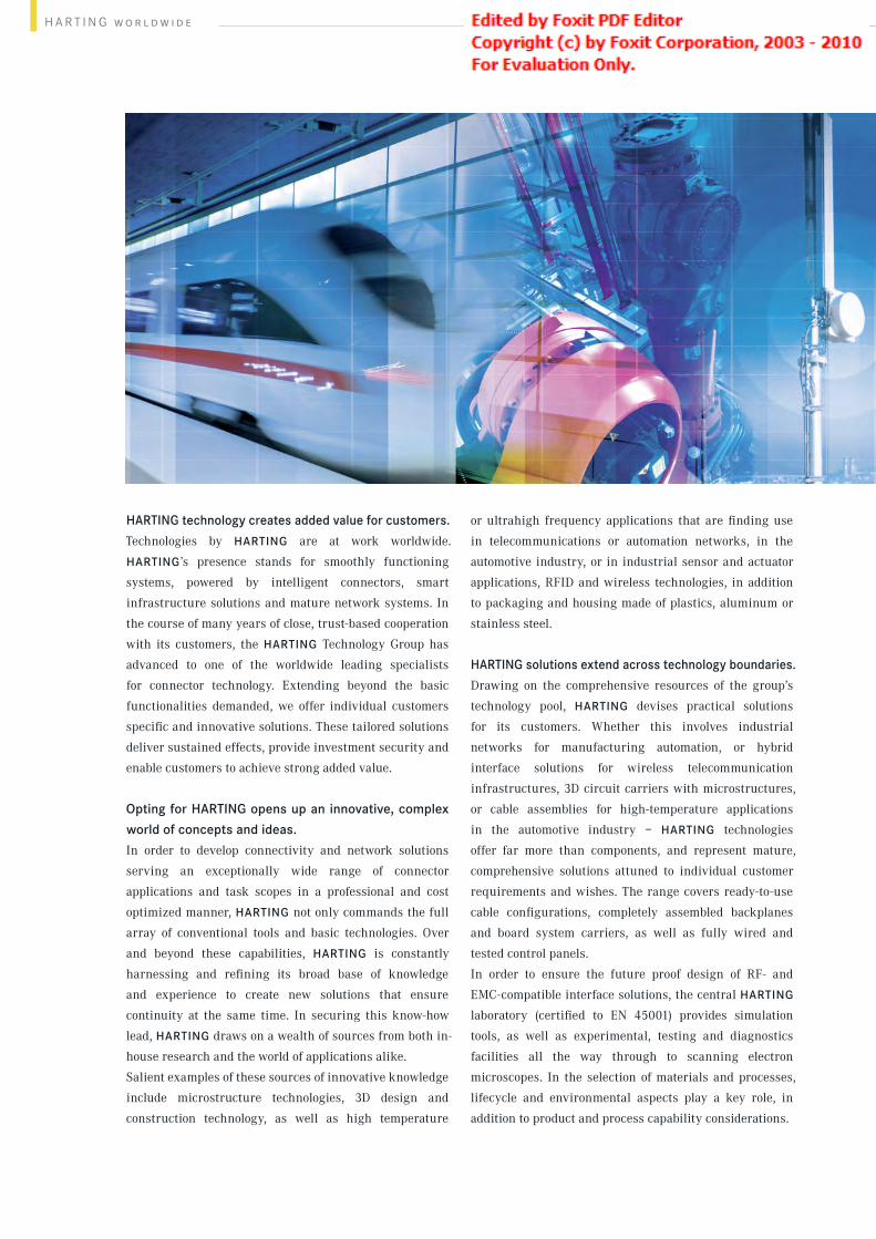
HARTING technology creates added value for customers.Technologies by HARTING are at work worldwide.
HARTING’s presence stands for smoothly functioning
systems, powered by intelligent connectors, smart
infrastructure solutions and mature network systems. In
the course of many years of close, trust-based cooperation
with its customers, the HARTING Technology Group has
advanced to one of the worldwide leading specialists
for connector technology. Extending beyond the basic
functionalities demanded, we offer individual customers
specific and innovative solutions. These tailored solutions
deliver sustained effects, provide investment security and
enable customers to achieve strong added value.
Opting for HARTING opens up an innovative, complex
world of concepts and ideas.In order to develop connectivity and network solutions
serving an exceptionally wide range of connector
applications and task scopes in a professional and cost
optimized manner, HARTING not only commands the full
array of conventional tools and basic technologies. Over
and beyond these capabilities, HARTING is constantly
harnessing and refining its broad base of knowledge
and experience to create new solutions that ensure
continuity at the same time. In securing this know-how
lead, HARTING draws on a wealth of sources from both in-
house research and the world of applications alike.
Salient examples of these sources of innovative knowledge
include microstructure technologies, 3D design and
construction technology, as well as high temperature
or ultrahigh frequency applications that are finding use
in telecommunications or automation networks, in the
automotive industry, or in industrial sensor and actuator
applications, RFID and wireless technologies, in addition
to packaging and housing made of plastics, aluminum or
stainless steel.
HARTING solutions extend across technology boundaries.Drawing on the comprehensive resources of the group’s
technology pool, HARTING devises practical solutions
for its customers. Whether this involves industrial
networks for manufacturing automation, or hybrid
interface solutions for wireless telecommunication
infrastructures, 3D circuit carriers with microstructures,
or cable assemblies for high-temperature applications
in the automotive industry – HARTING technologies
offer far more than components, and represent mature,
comprehensive solutions attuned to individual customer
requirements and wishes. The range covers ready-to-use
cable configurations, completely assembled backplanes
and board system carriers, as well as fully wired and
tested control panels.
In order to ensure the future proof design of RF- and
EMC-compatible interface solutions, the central HARTING
laboratory (certified to EN 45001) provides simulation
tools, as well as experimental, testing and diagnostics
facilities all the way through to scanning electron
microscopes. In the selection of materials and processes,
lifecycle and environmental aspects play a key role, in
addition to product and process capability considerations.
HARTING knowledge is practical know-how generating
synergy effects.HARTING commands decades of experience with
regard to the applications conditions of connectors in
telecommunications, computer and network technologies
and medical technologies, as well as industrial automation
technologies, such as the mechanical engineering
and plant engineering areas, in addition to the power
generation industry or the transportation sector. HARTING
is highly conversant with the specific application areas in
all of these technology fields.
The key focus is on applications in every solution
approach. In this context, uncompromising, superior
quality is our hallmark. Every new solution found will
invariably flow back into the HARTING technology pool,
thereby enriching our resources. And every new solution
we go on to create will draw on this wealth of resources in
order to optimize each and every individual solution. In
this way, HARTING is synergy in action.
Mac
hine
ryTr
an
sporta
tion
Solar Energy Wind Energy Power Generation and DistributionAutomation
Industrial Devices
TelecomEm
bedded Computing Systems Broadcast and Entertainment Medical Industrial Netw
orkInf
rast
ruct
ure
Backplanes
Industrial Connectors Actuator Systems
Cab
leAs
sem
blie
s
Asse
mbl
ylin
es3D Micropackages Advanced Tools
Vending Systems
PCBTechnologies
InformationTechnologies
ProductionTechnologies
Metal TreatmentTechnologies
Micro StructureTechnologies
NetworkTechnologies
Simulation
InterconnectTechnologies
Mechatronic

H A R T I N G w o r l d w i d e
HARTING technology creates added value for customers.Technologies by HARTING are at work worldwide.
HARTING’s presence stands for smoothly functioning
systems, powered by intelligent connectors, smart
infrastructure solutions and mature network systems. In
the course of many years of close, trust-based cooperation
with its customers, the HARTING Technology Group has
advanced to one of the worldwide leading specialists
for connector technology. Extending beyond the basic
functionalities demanded, we offer individual customers
specific and innovative solutions. These tailored solutions
deliver sustained effects, provide investment security
and enable customers to achieve strong added value.
Opting for HARTING opens up an innovative, complex
world of concepts and ideas.In order to develop connectivity and network solutions
serving an exceptionally wide range of connector
applications and task scopes in a professional and cost
optimized manner, HARTING not only commands the full
array of conventional tools and basic technologies. Over
and beyond these capabilities, HARTING is constantly
harnessing and refining its broad base of knowledge
and experience to create new solutions that ensure
continuity at the same time. In securing this know-how
lead, HARTING draws on a wealth of sources from both in-
house research and the world of applications alike.
Salient examples of these sources of innovative
knowledge include microstructure technologies, 3D
design and construction technology, as well as high
temperature or ultrahigh frequency applications that
are finding use in telecommunications or automation
networks, in the automotive industry, or in industrial
sensor and actuator applications, RFID and wireless
technologies, in addition to packaging and housing made
of plastics, aluminum or stainless steel.
HARTING solutions extend across technology boundaries.Drawing on the comprehensive resources of the group’s
technology pool, HARTING devises practical solutions
for its customers. Whether this involves industrial
networks for manufacturing automation, or hybrid
interface solutions for wireless telecommunication
infrastructures, 3D circuit carriers with microstructures,
or cable assemblies for high-temperature applications
in the automotive industry – HARTING technologies
offer far more than components, and represent mature,
comprehensive solutions attuned to individual customer
requirements and wishes. The range covers ready-to-use
cable configurations, completely assembled backplanes
and board system carriers, as well as fully wired and
tested control panels.
In order to ensure the future proof design of RF- and
EMC-compatible interface solutions, the central HARTING
laboratory (certified to EN 45001) provides simulation
tools, as well as experimental, testing and diagnostics
facilities all the way through to scanning electron
microscopes. In the selection of materials and processes,
lifecycle and environmental aspects play a key role, in
addition to product and process capability considerations.
HARTING knowledge is practical know-how generating
synergy effects.HARTING commands decades of experience with
regard to the applications conditions of connectors in
telecommunications, computer and network technologies
and medical technologies, as well as industrial automation
technologies, such as the mechanical engineering
and plant engineering areas, in addition to the power
generation industry or the transportation sector. HARTING
is highly conversant with the specific application areas in
all of these technology fields.
The key focus is on applications in every solution
approach. In this context, uncompromising, superior
quality is our hallmark. Every new solution found will
invariably flow back into the HARTING technology pool,
thereby enriching our resources. And every new solution
we go on to create will draw on this wealth of resources
in order to optimize each and every individual solution.
In this way, HARTING is synergy in action.
Mac
hine
ry
Tra
nsporta
tion S
olar Energy Wind Energy Power Generation and Distribution Automation Industrial Devices
Telecom Em
bedded Computing Systems Broadcast and Entertainment Medical Industria
l Netw
ork Infra
stru
ctur
e
Backplanes
Industrial Connectors Actuator Systems C
ab
le As
sem
blie
s
Asse
mbl
y lin
es
3D Micropackages Advanced Tools Vending Systems
PCB Technologies
InformationTechnologies
ProductionTechnologies
Metal TreatmentTechnologies
Micro StructureTechnologies
NetworkTechnologies
Simulation
InterconnectTechnologies
Mechatronic

HARTING eCatalogue
The HARTING eCatalogue / eShop can be found on our homepage at www.HARTING.com or at the direct link www.eCatalogue.HARTING.com.
The HARTING e-Catalogue is your platform for conveniently selecting individual products as well as configuring complete solutions. Our comprehensive product pages provide you with all necessary technical information and CAD files in various formats for downloading. You may also contact our technical sales department directly.
Find out about product innovations and news on the start page of the HARTING e-Catalogue or go directly to www.product-news.HARTING.com.
Registered users can take advantage of MyHARTING to check on availability or prices, and to place or track their orders. Here, your customized „HARTING history“ provides you with a list of your inquiries, quotations and more.
Sign up now for your free e-Catalogue account at HARTING!
www.eShop.HARTING.com

00·1
Contents Page
Summary Han®-sizes .............................................................................. 00.2
How to order connectors ........................................................................ 00.4
Hoods/housings connector insert protection .......................................... 00.5
Type of hoods/housings .......................................................................... 00.6
Locking systems ..................................................................................... 00.8
Connection technology ........................................................................... 00.9
Electrical engineering data ..................................................................... 00.18
Current carrying capacity ........................................................................ 00.21
Cross Reference from Pg thread to metric cable thread ........................ 00.23
Declaration of Conformity ....................................................................... 00.24
Han
Industrial Connectors

00·2
Han
Summary Han®-sizes
3 / 4 + 6 7 + 8 5 + 7 + 4 + 2
16 + 25 + 20
10 + 15 + 14
A
3
10
16
32
1 module
Size Description
Hood side-entry Hood top-entry
230/400 V 50 V 250 V 50 V 230/400 V 400 V 50 V 10 A 10 A 10 A 10 A 16 A 10 A 10 A Han® 3 A / 4 A Staf 6 Han® 7 D Han® 8 D Han® Q 5/0 Han® Q 7/0 Han-Brid® chapter 01 chapter 09 chapter 02 chapter 02 chapter 13 chapter 13 chapter 19
Housing Housing Housing bulkhead mounting surface mounting bulkhead mounting
Housing Hood screw mounting cable to cable coupling Hood top-entry Hood side-entry
250 V 250 V 50 V 50 V – 1000 V 16 A 10 A 10 A 5 A – 70 A Han A® Han D® Staf® Han-Modular® chapter 01 chapter 02 chapter 09 chapter 06
Housing bulkhead mounting Housing surface mounting Hood cable to cable coupling
suitable for 2 inserts of size 16 A

00·3
Han
Summary Han®-sizes
6
B
10
16
24
32 48
24 + 6 + 10 +
42 + 10 + 18 + 3 + 4/4 + 8/24 +
40 + 72 + 16 + 6 + 6 +
64 + 108 + 24 + 10 +
16 + 4/8 + 6/6 +
6/36 + 4/2 +
…
…
…
…
…
…
…
…
…
…
32 + 40 +
46 + 64 +
Size Description
Hood side-entry Hood top-entry
250 V 250 V 500 V 500 V 400/690 V 830 V 160 V – 690 V 50 V – 5000 V 10 A 10 A 16 A 16 A 35 A 16 A 10 A – 100 A 5 A – 200 A Han D® Han DD® Han E® Han® EE Han® HsB Han Hv E® Han-Com® Han- Han® ES Han® EEE Han® Hv ES Modular® chapter 02 chapter 02 chapter 03 chapter 03 chapter 07 chapter 04 chapter 05 chapter 06
Housing surface mounting Housing bulkhead mounting Hood cable to cable coupling
suitable for 2 inserts of size 16 B suitable for 2 inserts of size 24 B
2 modules
3 modules
4 modules
6 modules
00·4
Han
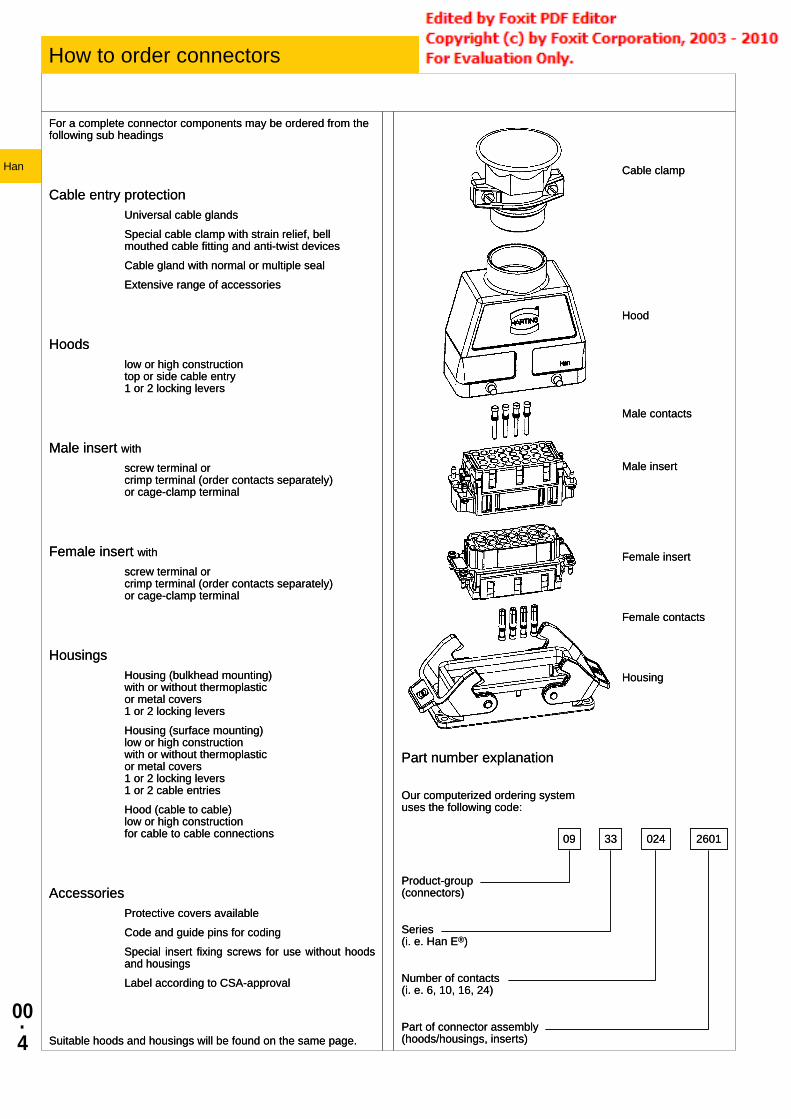
How to order connectors
26010243309
Part number explanation
Our computerized ordering system uses the following code:
Product-group (connectors)
Series (i. e. Han E®)
Number of contacts (i. e. 6, 10, 16, 24)
Part of connector assembly (hoods/housings, inserts)
For a complete connector components may be ordered from the following sub headings
Cable entry protectionUniversal cable glandsSpecial cable clamp with strain relief, bell mouthed cable fitting and anti-twist devicesCable gland with normal or multiple sealExtensive range of accessories
Hoodslow or high construction top or side cable entry 1 or 2 locking levers
Male insert withscrew terminal or crimp terminal (order contacts separately) or cage-clamp terminal
Female insert withscrew terminal or crimp terminal (order contacts separately) or cage-clamp terminal
HousingsHousing (bulkhead mounting) with or without thermoplastic or metal covers 1 or 2 locking leversHousing (surface mounting) low or high construction with or without thermoplastic or metal covers 1 or 2 locking levers 1 or 2 cable entriesHood (cable to cable) low or high construction for cable to cable connections
AccessoriesProtective covers availableCode and guide pins for codingSpecial insert fixing screws for use without hoods and housingsLabel according to CSA-approval
Suitable hoods and housings will be found on the same page.
Cable clamp
Hood
Male contacts
Male insert
Female insert
Female contacts
Housing

00·5
Han
Hoods/housings connector insert protection
0 0
1 1
2 2
3 3
4 4
5 5
6 6
7
8
9k *
The connector’s housing, sealing and locking mechanism protect the connection from external influences such as mechanical shocks, foreign bodies, humidity, dust, water or other fluids such as cleansing and cooling agents, oils, etc. The degree of protection the housing offers is explained in the IEC 60 529, DIN EN 60 529, standards that categorize enclosures according to foreign body and water protection.The following table shows the different degrees of protection.
Code letters First Index Figure Second Index Figure (International Protection) (Foreign bodies protection) (Water protection)
IP 6 5
Index Degree of protection figure Index Degree of protection figure
No protection against accidental contact, no protection against solid foreign bodies
No protection
No protection against water
No protection against water
Protection against contact with any large area by hand and against large solid foreign bodies with Ø > 50 mm
Protection against lar-ge foreign bodies
Protection against vertical water drips
Drip-proof
Protection against con-tact with the fingers, protection against solid foreign bodies with Ø > 12 mm
Protection against medium sized foreign bodies
Protection against water drips (up to a 15° angle)
Drip-proof
Protection against tools, wires or similar objects with Ø > 2.5 mm, protection against small foreign solid bodies with Ø > 2.5 mm
Protection against small solid foreign bodies
Protection against diagonal water drips (up to a 60° angle)
Spray-proof
As 3 however Ø > 1 mm
Protection against grain-shaped foreign bodies
Protection against splashed water from all directions
Splash-proof
Full protection against contact. Protection against interior injurious dust deposits
Protection against injurious deposits of dust
Protection against water (out of a nozzle) from all directions
Hose-proof
Total protection against contact. Protection against penetration of dust
Protection against ingress of dust
Protection against strong water (out of a nozzle) from all directions
Strong hose-proof
Protected against temporary immersion
Protected against immersion
Protected against water pressure
Protected against water from high-pressure / steam jet cleaners
Water-tight
Protected against high- pressure
Description according to IEC 60529* ... IP 9k is not part of IEC 60529

00·6
Han
Type of hoods/housings
Standard Hoods/Housings Field of application for excellent mechanical and electrical
protection in demanding environments, for example, in the automobile and mechanical engineering industries also for process and regulation control appli-cations
Distinguishing feature hoods/housings colour-coded grey (RAL 7037) Material of hoods/housings Die cast light alloy Locking levers Han-Easy Lock®
Cable entry protection Optional special cable clamp for hoods with strain relief, bell mouthed cable fitting and anti-twist devices
Han® M Hoods/Housings for harsh environmental requirements
Field of application for all applications where aggressive environmental conditions and extreme climatic atmospheres are encountered
Distinguishing feature hoods/housings colour-coded black (RAL 9005)
Material of hoods/housings Die cast light alloy, corrosion resistant Locking levers Corrosion resistant stainless steel Cable entry protection Special cable clamp for hoods with strain
relief, bell mouthed cable fitting and anti-twist devices
Han® EMC Hoods/Housings with high shielding efficiency
Field of application For sensitive interconnections that have to be shielded against electrical, magnetic or electro-magnetic inter-ferences
Distinguishing feature Electrically conductive surface, internal seal
Material of hoods/housings Die cast light alloy Locking levers Han-Easy Lock®
Cable entry protection EMC cable clamp in order to connect the cable shielding to the hood without interruption of the shielding
Han® HPR Hoods/Housings, pressure tight Field of application For external electrical interconnec-
tions in vehicles, in highly demanding environments and wet areas, as well as for sensitive interconnections that have to be shielded
Distinguishing feature hoods/housings colour-coded black, internal seal (RAL 9005)
Locking parts Stainless steel Material of hoods/housings Die cast light alloy, corrosion resistant Cable entry protection Optional universal cable clamp for
hoods with strain relief, or special cable clamp with bell mouthed cable fitting and anti-twist devices (use of adapter is necessary)
Han-INOX® Hoods/Housings Field of application for excellent mechanical and
electrical protection in demanding environments, for example, in the food, automobile and mechanical engineering industries also for process and regulation control appli-cations
Distinguishing feature matt-finished metal surfaceMaterial of hoods/housings Stainless steelLocking levers Stainless steel
Series Number of screws Size of screws
Recommended Tightening torque (Nm)
Remarks
Han® 3 A 2 M 3 0.8 ... 1.0 GasketHan® 10 A / 16 A 4 M 3 0.8 ... 1.0 Gasket
Han® 15 EMV / 25 EMV 4 M 3 min. 1.0 O-ringHan® 32 A 4 M 4 0.8 ... 1.0 Gasket
Han® 6 B / 10 B / 16 B / 24 B 4 M 4 0.8 ... 1.0 GasketHan® 32 B 4 M 5 min. 2.5 O-ringHan® 48 B 4 M 6 min. 3.0 O-ring
Han® 3 HPR 2 M 4 min. 1.0 O-ringHan® 6 / 10 / 16 / 24 HPR 4 M 6 min. 3.0 O-ring
Han® 48 HPR 4 M 8 min. 5.0 O-ring
To offer safe protection the surface condition for mounting panel should be according to DIN 4766: • Waviness ≤ 0.2 mm on 200 mm distance • Roughness Ra ≤ 16 µm
During assembly and handling of the connector, any kind of damage to the surface of the housing must be avoided to guarantee the correct surface protection.
00·7
Han
Type of hoods/housings
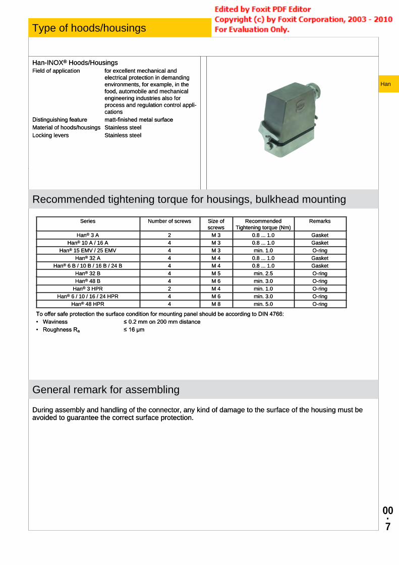
Han-INOX® Hoods/Housings Field of application for excellent mechanical and
electrical protection in demanding environments, for example, in the food, automobile and mechanical engineering industries also for process and regulation control appli-cations
Distinguishing feature matt-finished metal surfaceMaterial of hoods/housings Stainless steelLocking levers Stainless steel
Recommended tightening torque for housings, bulkhead mounting
Series Number of screws Size of screws
Recommended Tightening torque (Nm)
Remarks
Han® 3 A 2 M 3 0.8 ... 1.0 GasketHan® 10 A / 16 A 4 M 3 0.8 ... 1.0 Gasket
Han® 15 EMV / 25 EMV 4 M 3 min. 1.0 O-ringHan® 32 A 4 M 4 0.8 ... 1.0 Gasket
Han® 6 B / 10 B / 16 B / 24 B 4 M 4 0.8 ... 1.0 GasketHan® 32 B 4 M 5 min. 2.5 O-ringHan® 48 B 4 M 6 min. 3.0 O-ring
Han® 3 HPR 2 M 4 min. 1.0 O-ringHan® 6 / 10 / 16 / 24 HPR 4 M 6 min. 3.0 O-ring
Han® 48 HPR 4 M 8 min. 5.0 O-ring
To offer safe protection the surface condition for mounting panel should be according to DIN 4766: • Waviness ≤ 0.2 mm on 200 mm distance • Roughness Ra ≤ 16 µm
General remark for assembling
During assembly and handling of the connector, any kind of damage to the surface of the housing must be avoided to guarantee the correct surface protection.
00·8
Han
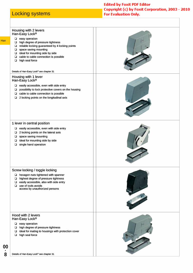
Locking systems
Housing with 2 levers Han-Easy Lock®
❑ easy operation ❑ high degree of pressure tightness ❑ reliable locking guaranteed by 4 locking points ❑ space saving mounting ❑ ideal for mounting side by side ❑ cable to cable connection is possible ❑ high seal force
Details of Han-Easy Lock® see chapter 31
Housing with 1 lever Han-Easy Lock®
❑ easily accessible, even with side entry ❑ possibility to lock protective covers on the housing ❑ cable to cable connection is possible ❑ 2 locking points on the longitudinal axis
1 lever in central position ❑ easily accessible, even with side entry ❑ 2 locking points on the lateral axis ❑ space saving mounting ❑ ideal for mounting side by side ❑ single hand operation
Screw locking / toggle locking ❑ hexagon nuts tightened with spanner ❑ highest degree of pressure tightness ❑ easily accessible, also with side entry ❑ use of tools avoids
access by unauthorized persons
Hood with 2 levers Han-Easy Lock®
❑ easy operation ❑ high degree of pressure tightness ❑ ideal for mating to housings with protection cover ❑ high seal force
Details of Han-Easy Lock® see chapter 31
Crimp connectionHan DD®
Han D®
R 15Han-Modular® (10 A)Han E®
Han A®
Han Hv E®
Han-Com® (40 A)Han-Modular® ( 40 A)Han E®
Han A®
Han Hv E®
Han® EEHan® EEEHan-Modular® (16 A)Han® Q
A perfect crimp connection is gastight, therefore corrosion free and amounts to a cold weld of the parts being connected. For this reason, major features in achieving high quality crimp connections are the design of the contact crimping parts and of course the crimping tool itself. Wires to be connected must be carefully matched with the correct size of crimp contacts. If these basic requirements are met, users will be assured of highly relia-ble connections with low contact resistance and high resistance to corrosive attack.The economic and technical advantages are:● Constantcontactresistanceasaresultofpreciselyrepeated
crimp connection quality● Corrosionfreeconnectionsasaresultofcoldweldaction● Pre-preparationofcableformswithcrimpcontactsfitted● OptimumcostcableconnectionRequirements for crimp connectors are laid down in DIN EN 60 352-2 as illustrated in the table.PulloutforceofstrandedwireThe main criterion by which to judge the quality of a crimp con-nection is the retention force achieved by the wire conductor in theterminalsectionofthecontact.DINEN60352-2definestheextraction force in relation to the cross-section of the conductor. WhenfittedusingHARTINGcrimpingtoolsandsubjecttotheirutilization in an approved manner, our crimp connectors comply with the required extraction forces.Crimping toolsCrimping tools (hand operated or automatic) are carefully desi-gned to produce with high pressure forming parts a symmetrical connection of the crimping part of the contact and the wire being connected with the minimum increase in size at the connection point. The positioner automatically locates the crimp and wire at the correct point in the tool.A ratchet in the tool performs 2 functions:● Itpreventsinsertionofthecrimpintothetoolforcrimping
before the jaws are fully open● Itpreventsthetoolbeingopenedbeforethecrimpingactionis
completed
00·9
Han
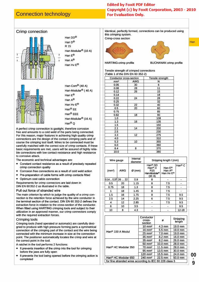
Connection technology
Crimp connectionHan DD®
Han D®
R 15Han-Modular® (10 A)Han E®
Han A®
Han Hv E®
Han-Com® (40 A)Han-Modular® ( 40 A)Han E®
Han A®
Han Hv E®
Han® EEHan® EEEHan-Modular® (16 A)Han® Q
A perfect crimp connection is gastight, therefore corrosion free and amounts to a cold weld of the parts being connected. For this reason, major features in achieving high quality crimp connections are the design of the contact crimping parts and of course the crimping tool itself. Wires to be connected must be carefully matched with the correct size of crimp contacts. If these basic requirements are met, users will be assured of highly relia-ble connections with low contact resistance and high resistance to corrosive attack.The economic and technical advantages are:● Constantcontactresistanceasaresultofpreciselyrepeated
crimp connection quality● Corrosionfreeconnectionsasaresultofcoldweldaction● Pre-preparationofcableformswithcrimpcontactsfitted● OptimumcostcableconnectionRequirements for crimp connectors are laid down in DIN EN 60 352-2 as illustrated in the table.PulloutforceofstrandedwireThe main criterion by which to judge the quality of a crimp con-nection is the retention force achieved by the wire conductor in theterminalsectionofthecontact.DINEN60352-2definestheextraction force in relation to the cross-section of the conductor. WhenfittedusingHARTINGcrimpingtoolsandsubjecttotheirutilization in an approved manner, our crimp connectors comply with the required extraction forces.Crimping toolsCrimping tools (hand operated or automatic) are carefully desi-gned to produce with high pressure forming parts a symmetrical connection of the crimping part of the contact and the wire being connected with the minimum increase in size at the connection point. The positioner automatically locates the crimp and wire at the correct point in the tool.A ratchet in the tool performs 2 functions:● Itpreventsinsertionofthecrimpintothetoolforcrimping
before the jaws are fully open● Itpreventsthetoolbeingopenedbeforethecrimpingactionis
completed
Identical, perfectly formed, connections can be produced using this crimping system.Crimp-cross section
HARTING-crimpprofile BUCHANANcrimpprofile
Tensile strength of crimped connections (Table 1 of the DIN EN 60 352-2)
Conductor cross-section Tensile strengthmm² AWG N0.05 30 60.08 28 110.12 26 150.14 180.22 24 280.25 320.32 22 400.5 20 600.75 850.82 18 901.0 1081.3 16 1351.5 1502.1 14 2002.5 2303.3 12 2754.0 3105.3 10 3556.0 3608.4 8 37010.0 380
Wire gauge Internal diameter Stripping length l (mm)
(mm²) AWG Ø (mm)
Han® DDHan® D
R15Han-Modular®
(10 A)
Han E®Han A®
Han Hv E®
Han® C
0.14 ... 0.37 26 ... 22 0.9 8 - -0.5 20 1.15 8 7.5 -0.75 18 1.3 8 7.5 -
1 18 1.45 8 7.5 -1.5 16 1.75 8 7.5 9.52.5 14 2.25 6 7.5 9.54 12 2.85 - 7.5 9.56 10 3.5 - - 9.510 8 4.3 - - 12-18
Conductor cross-section
ø Stripping length
Han® 100 A Modul
10 mm² 4.3 mm 19.0 mm 16 mm² 5.5 mm 19.0 mm 25 mm² 7.0 mm 19.0 mm 35 mm² 8.2 mm 16.0 mm
Han® HC Modular 350
35 mm² 8.2 mm 26.0 mm 50 mm² 10.0 mm 28.0 mm 70 mm² 11.5 mm 28.0 mm 95 mm² 13.5 mm 30.0 mm120 mm² 15.5 mm 24.0 mm
Han® HC Modular 650 240 mm² 22.5 mm 50.0 mmforfinestrandedwiresaccordingtoIEC60228class5

00·
10
Han
Connection technology
Screw terminal
Screw terminals meet VDE 0609 /EN 60 999. Dimensions and tightening torques for testing are shown in following table.Screw dimensions and tightening torque for screw terminals
Wire gauge (mm²) 1.5 2.5 4 6 10 16Screw thread M3 M3 M3.5 M4 M4 M6
Test moment of torque (Nm)
0.5 0.5 0.8 1.2 1.2 1.2*
min. pull-out for stranded wire (N)
40 50 60 80 90 100
* for screws without heads
The relevant regulations state that in the case of
● Terminalswithwireprotection
the use of ferrules is not necessary. Series Han E®, Han® HsB, Han Hv E®, Han® K 6/12, Han® K 6/6
● Terminalswithoutwireprotection
Theinsulationisfirststrippedandthenawireferrulemustbeused. Series Han® K 4/x, Han A®, Staf®
Screw terminal
InsertsWire protection min. wire gauge max. wire gauge* Stripping length
Yes No mm² AWG mm² AWG mm
Han® 3 A, Han® 4 A X 0.75 18 1.5 16 4.5
Han® 10 A, 16 A, 32 A X 0.75 18 2.5 14 7.5
Han E®, Hv E® X 0.75 18 2.5 14 7.5
Han® HsB X 1.5 16 6 10 11.5
Han® K 6/6, K 6/12 (signal contacts) X 0.2 24 2.5 14 7.5
Han® K 4/2, K 4/8 (signal contacts) X 0.5 20 2.5 14 7.5
Han® K 4/0, K 4/2, K 4/8 (power contacts) X 1.5 16 16 6 14
Han E® AV, Han D® AV X 0.2 24 2.5 14 8 ... 11
Staf® X 0.5 18 1.5 16 4.5
* Rated wire gauge according to DIN EN 60 999-1
Screw terminal
Screw terminals meet VDE 0609 /EN 60 999. Dimensions and tightening torques for testing are shown in following table.Screw dimensions and tightening torque for screw terminals
Wire gauge (mm²) 1.5 2.5 4 6 10 16Screw thread M3 M3 M3.5 M4 M4 M6
Test moment of torque (Nm)
0.5 0.5 0.8 1.2 1.2 1.2*
min. pull-out for stranded wire (N)
40 50 60 80 90 100
* for screws without heads
The relevant regulations state that in the case of
● Terminalswithwireprotection
the use of ferrules is not necessary. Series Han E®, Han® HsB, Han Hv E®, Han® K 6/12, Han® K 6/6
● Terminalswithoutwireprotection
Theinsulationisfirststrippedandthenawireferrulemustbeused. Series Han® K 4/x, Han A®, Staf®
Screw terminal
InsertsWire protection min. wire gauge max. wire gauge* Stripping length
Yes No mm² AWG mm² AWG mm
Han® 3 A, Han® 4 A X 0.75 18 1.5 16 4.5
Han® 10 A, 16 A, 32 A X 0.75 18 2.5 14 7.5
Han E®, Hv E® X 0.75 18 2.5 14 7.5
Han® HsB X 1.5 16 6 10 11.5
Han® K 6/6, K 6/12 (signal contacts) X 0.2 24 2.5 14 7.5
Han® K 4/2, K 4/8 (signal contacts) X 0.5 20 2.5 14 7.5
Han® K 4/0, K 4/2, K 4/8 (power contacts) X 1.5 16 16 6 14
Han E® AV, Han D® AV X 0.2 24 2.5 14 8 ... 11
Staf® X 0.5 18 1.5 16 4.5
* Rated wire gauge according to DIN EN 60 999-1

00·
11
Han
Connection technology
Recommended screw drivers and tightening torques
Screw size Connector type Tightening torque (Nm)
Tightening torque (lbft)
Recommended screw driver
M3 Screw terminals: Han® 3A /4A /Q5/0 (PE) / Staf® 0.25 0.20 slotted 0.4 x 2.5
M3 Screw terminals: Han D® AV, Han E® AV, Han® K6/6, K6/12 (signal) 0.5 0.4 slotted 0.5 x 3.0
M3 Screw terminals: Han® 10A - 32A, Han® E, Hv E®, Han® HsB 0.5 0.4 slotted 0.6 x 3.5 or PH 1
M3 Han® fixing screws 0.5 0.4slotted 0.6 x 3.5
or PH 1 or PH 2
M3 Han® guiding pins and bushes 0.5 0.4 slotted 1 x 6.0
M3.5 Ground terminals: Han® 10A, Han® 16A, Han 15 D®, Han 25 D® 0.8 0.6 slotted 0.6 x 3.5
or PH 1
M4 Screw terminals: Han® HsB 1.20 0.90 slotted 0.6 x 3.5 or PH 1
M4 Ground terminals: Han E®, Han 40 D®, Han 64 D®, Han DD®, Han® K 8/24, K6/6, K8/0 1.20 0.90 slotted 0.8 x 4.5
or PH 2
M5 Ground terminals: Han® HsB, Han® K12/2, K4/X, K6/12, K6/36 2 1.40 slotted 0.8 x 4.5 or PH 2
M6 Screw terminals: Han® K power contacts, Han-Eco® PE module
for Han® K see chapter 05, Han-Eco® PE module (1,2-3 Nm) slotted 0,8 x 4,5
Preferred size
Increasing the tightening torque does not improve considerably the contact resistances.The torque moments were determined when optimum mechanical, thermal and electrical circumstances were given. If the recommended figures are considerably exceeded the wire or the termination can be damaged.

00·
12
Han
Connection technology
① ② ③ ④
Han-Quick Lock® termination technique This new termination technique from HARTING combines the re-liability and the simple operation of the cage clamp termination with the low space requirements of crimp technology.Han-Quick Lock® is ideally suited to high contact densities and is considerably superior over other termination techniques. No other technology is so simple, space saving and fast. For this vibration safe termination, no special tools are necessary.● Fast,simpleandrobustterminationtechnique● Fieldassemblywithoutaspecialtool● Compatiblealsotoinsertswithothertermination
technologies● Combines high contact density similar to crimp termination
with the simple connection like a cage clamp terminal
Insert connectors: Han® 3 A Han® 4 A Han® 7 D Han® 8 D Han® Q 4/2 Han® Q 5/0 Han® Q 8/0 Han® Q 12/0 Han® EE modules Han® DD modules Han® PushPull Power 4/0
Technical characteristics:Material
Isolation body PolycarbonateActive termination element PolycarbonateQuick-Lock spring Stainless steelContact Copperalloy
Blue slide Terminal cross-section 0.5 ... 2.5 mm² / AWG 20 ... 14
Black slide Terminal cross-section 0.25 ... 1.5 mm² / AWG 23 ... 16
Stripping length 10 mm Insulating resistance > 1010 OhmFlammability according to UL 94 V 0Termination tool Screwdriver
0.4 x 2.5 mm bzw. 0.5 x 3.0 mm
Axial screw terminal
Thisterminationcombinesthebenefitsofscrewandcrimptermi-nations:● Lessspacerequired● Easyhandling● Nospecialtools
Remarks on the axial screw techniqueThe wire gauges mentioned in the catalogue refer to geometric wire gauges of cables.Background:According to DIN VDE 0295 for cables and insulated wires the wiregaugewillbedeterminedbyconductance(Ω/km)andmaxi-mumwirediameter.Aminimumcablediameterisnotspecified! (Example:nominalwiregauge95mm²→real,geometricwiregauge89mm²)Recommendation:The use of cables with an extreme geometric wire gauge deviati-on should be checked separately with the use of the axial screw termination.

00·
13
Han
Connection technology
Axial screw terminal
This termination combines the benefits of screw and crimp termi-nations:● Less space required● Easy handling● No special tools
Remarks on the axial screw techniqueThe wire gauges mentioned in the catalogue refer to geometric wire gauges of cables.Background:According to DIN VDE 0295 for cables and insulated wires the wire gauge will be determined by conductance (Ω/km) and maxi-mum wire diameter. A minimum cable diameter is not specified! (Example:nominal wire gauge 95 mm² → real, geometric wire gauge 89 mm²)Recommendation:The use of cables with an extreme geometric wire gauge deviati-on should be checked separately with the use of the axial screw termination.
Strain relief:For safe operation the cable must be fixed at an adequate distance from the terminal to ensure that the contact is protected against radial stress. Details for professional strain relief design can be found in the standard DIN VDE 0100-520: 2003-06 (see enclosed table).
Outer cable diameter (mm)
Maximum fixing distance (mm)
horizontal verticalD ≤ 9 250 400
9 < D < 15 300 40015 < D < 20 350 45020 < D < 40 400 550
Cables:The axial screw technology is developed for wires according to DIN EN 60 228 class 5 (see table: Wire assembly according to DIN EN 60 228). Deviating cable assemblies have to be tested separately.
Assembly remarks:Before starting the assembly the user must ensure that the axial cone is screwed fully downward to completely open the contact chamber.After stripping the cable insulation the strands must not be twisted and the maximum cable insulation must not exceed the recommended dimension.Insert the wire completely into the contact chamber until the copper strands reach the bottom. Keep the cable in position while applying the recommended tightening torque.
Maintenance of the axial screw termination:After initial assembly it is only allowed to reapply the recommen-ded tightening torque once in order to avoid damage to individual cable strands.
Wire gauge (mm²)
Stranded wires DIN EN 60 228 class 2
Fine stranded wires DIN EN 60 228 class 5
Super fine stranded wires DIN EN 60 228 class 6
0.5 7 x 0.30 16 x 0.20 28 x 0.15 64 x 0.10 131 x 0.07 256 x 0.050.75 7 x 0.37 24 x 0.20 42 x 0.15 96 x 0.10 195 x 0.07 384 x 0.05
1 7 x 0.43 32 x 0.20 56 x 0.15 128 x 0.10 260 x 0.07 512 x 0.051.5 7 x 0.52 30 x 0.25 84 x 0.15 192 x 0.10 392 x 0.07 768 x 0.052.5 7 x 0.67 50 x 0.25 140 x 0.15 320 x 0.10 651 x 0.07 1280 x 0.054 7 x 0.85 56 x 0.30 224 x 0.15 512 x 0.10 1040 x 0.076 7 x 1.05 84 x 0.30 192 x 0.20 768 x 0.10 1560 x 0.0710 7 x 1.35 80 x 0.40 320 x 0.20 1280 x 0.10 2600 x 0.0716 7 x 1.70 128 x 0.40 512 x 0.20 2048 x 0.1025 7 x 2.13 200 x 0.40 800 x 0.20 3200 x 0.1035 7 x 2.52 280 x 0.40 1120 x 0.2050 19 x 1.83 400 x 0.40 705 x 0.3070 19 x 2.17 356 x 0.50 990 x 0.3095 19 x 2.52 485 x 0.50 1340 x 0.30120 37 x 2.03 614 x 0.50 1690 x 0.30150 37 x 2.27 765 x 0.50 2123 x 0.30185 37 x 2.52 944 x 0.50 1470 x 0.40240 61 x 2.24 1225 x 0.50 1905 x 0.40
Wire assembly according to DIN EN 60 228

00·
14
Han
Connection technology
Insert Wire gauge
Stripping length Tightening torque
Max. cable insulation diameter
Size hexagon recess
Insert dimension for cable
indication (ISK)(mm²) (mm) (Nm) (mm) (SW) (mm)
Han® K 4/4 finger proofed 6 ... 16 6 mm²: 10 mm²: 16 mm²:
11+1 11+1 11+1
6 mm²: 10 mm²: 16 mm²:
2 3 4
8.9 2.5 7.4 PE: 8.9
10 ... 22 10 mm²: 16 mm²: 22 mm²:
11+1 11+1 11+1
10 mm²: 16 mm²: 22 mm²:
3 4 4
8.9 8.9 11
2.5 7.4 7.4 5.4
PE: 8.9 Han® K 4/4 6 ... 16 6 mm²:
10 mm²: 16 mm²:
11+1 11+1 11+1
6 mm²: 10 mm²: 16 mm²:
2 3 4
8.9 2.5 7.4 PE: 8.9
10 ... 22 10 mm²: 16 mm²: 22 mm²:
11+1 11+1 13+1
10 mm²: 16 mm²: 22 mm²:
3 4 4
8.9 8.9 11
2.5 7.4 7.4 5.4
PE: 8.9Han® K 6/12 2.5 ... 8 2.5 mm²:
4 mm²: 6 mm²: 8 mm²:
5+1 5+1 8+1 8+1
2.5 mm²: 4 mm²: 6 mm²: 8 mm²:
1.5 1.5 2 2
6.2 2 7.4
6 ... 10 6 mm²: 8 mm²:
10 mm²:
8+1 8+1 8+1
6 mm²: 8 mm²:
10 mm²:
2 2 2
6.2 2 4.7
Han® K 6/6 10 ... 25 10 mm²: 16 mm²: 25 mm²:
13+/-1 13+/-1 13+/-1
10 mm²: 16 mm²: 25 mm²:
6 6 7
11.4 4 4.9
16 ... 35 16 mm²: 25 mm²: 35 mm²:
13+/-1 13+/-1 13+/-1
16 mm²: 25 mm²: 35 mm²:
6 7 8
11.4 4 4.9
Han® K 8/0 10 ... 25 10 mm²: 16 mm²: 25 mm²:
13+/-1 13+/-1 13+/-1
10 mm²: 16 mm²: 25 mm²:
6 6 7
11.4 4 4.75
Han® Q 2/0 Han® Q 2/0 High Voltage
2.5 ... 10 2.5 mm²: 4 mm²: 6 mm²:
10 mm²:
8+1 8+1 8+1 8+1
2.5 mm²: 4 mm²: 6 mm²:
10 mm²:
1.8 1.8 1.8 1.8
7.3 2 5.6
Han® Q 4/2 Han® Q 4/2 with Han-Quick Lock®
4 ... 10 4 mm²: 6 mm²:
10 mm²:
8+1 8+1 8+1
4 mm²: 6 mm²:
10 mm²:
1.8 1.8 1.8
7.3 2 5.6
Han® 200 A module without PE Han® 200 A module with PE
25 ... 40 25 mm²: 40 mm²:
16 16
25 mm²: 40 mm²:
8 8
12 16
5 0
40 ...70 40 mm²: 70 mm²:
16 16
40 mm²: 70 mm²:
9 10
12 16
5 0
Han® 100 A module 6 ... 10 6 mm²: 8 mm²:
10 mm²:
13+/-1 13+/-1 13+/-1
6 mm²: 8 mm²:
10 mm²:
4 4 4
11.4 2.5 4.9
10 ... 25 10 mm²: 16 mm²: 25 mm²:
13+/-1 13+/-1 13+/-1
10 mm²: 16 mm²: 25 mm²:
6 6 7
11.4 4 4.9
16 ... 35 16 mm²: 25 mm²: 35 mm²:
13+/-1 13+/-1 13+/-1
16 mm²: 25 mm²: 35 mm²:
6 7 8
11.4 4 4.9
38 38 mm²: 13+/-1 38 mm²: 8 11.4 4 4.9Han® 70 A module 6 ... 16 6 mm²:
10 mm²: 16 mm²:
11+1 11+1 11+1
6 mm²: 10 mm²: 16 mm²:
2 3 4
8.9 2.5 7.4
14 ... 22 14 mm²: 16 mm²: 22 mm²:
12.5+1 12.5+1 12.5+1
14 mm²: 16 mm²: 22 mm²:
4 4 4
10 2.5 5.9
Han® 40 A module 2.5 ... 8 2.5 mm²: 4 mm²: 6 mm²: 8 mm²:
5+1 5+1 8+1 11+1
2.5 mm²: 4 mm²: 6 mm²:
10 mm²:
1.5 1.5 2 2
4 4 6
10.5
2 4.7
6 ... 10 6 mm²: 10 mm²:
8+1 11+1
6 mm²: 10 mm²:
2 2
6 10.5
2 4.7

00·
15
Han
Connection technology
Insert Wire gauge
Stripping length Tightening torque
Max. cable insulation diameter
Size hexagon recess
Insert dimension for cable
indication (ISK)(mm²) (mm) (Nm) (mm) (SW) (mm)
Han® C module with axial screw terminal
2.5 ... 8 2.5 mm²: 4 mm²: 6 mm²: 8 mm²:
5+1 5+1 8+1 8+1
2.5 mm²: 4 mm²: 6 mm²: 8 mm²:
1.5 1.5 2 2
4 4 6
8.2
2 5.2
6 ... 10 6 mm²: 10 mm²:
8+1 11+1
6 mm²: 10 mm²:
2 2
6 8.2
2 5.2
Han® K3/0 straight 25 ... 40 25 mm²: 40 mm²:
22 22
25 mm²: 40 mm²:
8 8
15 5 8.2
35 ... 70 35 mm²: 50 mm²: 70 mm²:
22 22 22
35 mm²: 50 mm²: 70 mm²:
8 9 10
15 5 8.2
Han® K3/0 angled 25 ... 40 25 mm²: 40 mm²:
22 22
25 mm²: 40 mm²:
8 8
15 5 9
35 ... 70 35 mm²: 50 mm²: 70 mm²:
22 22 22
35 mm²: 50 mm²: 70 mm²:
8 9 10
15 5 9
Han® K3/2 straight 35 ... 70 PE: 25 ... 40
35 mm²: 50 mm²: 70 mm²:
PE:
22 22 22 14
35 mm²: 50 mm²: 70 mm²:
8 9 10
power: 15
PE: 10
5 power: 8.2
PE: 7.2Han® K3/2 angled 25 ... 40 25 mm²:
40 mm²: PE:
22 22 14
25 mm²: 40 mm²:
8 8
power: 15
PE: 10
5 power: 9.0
PE: 7.235 ... 70
PE: 25 ... 4035 mm²: 50 mm²: 70 mm²:
22 22 22
35 mm²: 50 mm²: 70 mm²:
8 9 10
power: 15 PE: 10
5 power: 9.0 PE: 7.2
Han® HC Modular 350 20 ... 35 20 mm²: 35 mm²:
19+1 19+1
20 mm²: 35 mm²:
8 8
19.5 5 13
35 ... 70 35 mm²: 50 mm²: 70 mm²:
19+1 19+1 19+1
35 mm²: 50 mm²: 70 mm²:
8 10 12
19.5 5 13
95 ... 120 95 mm²: 120 mm²:
19+1 19+1
95 mm²: 120 mm²:
14 16
19.5 5 13
Ground contact for Han® HC Modular
35 ... 70 35 mm²: 50 mm²: 70 mm²:
19+1 19+1 19+1
35 mm²: 50 mm²: 70 mm²:
8 10 12
- 5 -
Han® HC Modular 650 60 ... 70 60 mm²: 70 mm²:
23+2 23+2
60 mm²: 70 mm²:
12 12
27 8 28
70 ... 120 70 mm²: 95 mm²:
120 mm²:
23+2 23+2 23+2
70 mm²: 95 mm²:
120 mm²:
12 14 16
26.5 8 28
150 ... 185 150 mm²: 185 mm²:
23+2 23+2
150 mm²: 185 mm²:
17 18
26.5 8 28
Overview inserts with axial screw terminal
Insulating base dimension for the cable marking (ISK)Marking the proper cable position for the axial screw connection contact point:The user can attach a marker to the cable sheathing in order to specify the proper point for tightening the axial screw on the connecting cable. If the cable in pushed into the insulating base up to the marker (where the marker is flush with the upper edge of the insulating base), then the cable is in the proper position and may be connected. The following figure (on the next page) illustrates this process when using the Han® HC Modular 350 contact. The marker and the upper edge of the insulating base are at the same level (as indicated by the dashed line).
Insert Wire gauge
Stripping length Tightening torque
Max. cable insulation diameter
Size hexagon recess
Insert dimension for cable
indication (ISK)(mm²) (mm) (Nm) (mm) (SW) (mm)
Han® K 4/4 finger proofed 6 ... 16 6 mm²: 10 mm²: 16 mm²:
11+1 11+1 11+1
6 mm²: 10 mm²: 16 mm²:
2 3 4
8.9 2.5 7.4 PE: 8.9
10 ... 22 10 mm²: 16 mm²: 22 mm²:
11+1 11+1 11+1
10 mm²: 16 mm²: 22 mm²:
3 4 4
8.9 8.9 11
2.5 7.4 7.4 5.4
PE: 8.9 Han® K 4/4 6 ... 16 6 mm²:
10 mm²: 16 mm²:
11+1 11+1 11+1
6 mm²: 10 mm²: 16 mm²:
2 3 4
8.9 2.5 7.4 PE: 8.9
10 ... 22 10 mm²: 16 mm²: 22 mm²:
11+1 11+1 13+1
10 mm²: 16 mm²: 22 mm²:
3 4 4
8.9 8.9 11
2.5 7.4 7.4 5.4
PE: 8.9Han® K 6/12 2.5 ... 8 2.5 mm²:
4 mm²: 6 mm²: 8 mm²:
5+1 5+1 8+1 8+1
2.5 mm²: 4 mm²: 6 mm²: 8 mm²:
1.5 1.5 2 2
6.2 2 7.4
6 ... 10 6 mm²: 8 mm²:
10 mm²:
8+1 8+1 8+1
6 mm²: 8 mm²:
10 mm²:
2 2 2
6.2 2 4.7
Han® K 6/6 10 ... 25 10 mm²: 16 mm²: 25 mm²:
13+/-1 13+/-1 13+/-1
10 mm²: 16 mm²: 25 mm²:
6 6 7
11.4 4 4.9
16 ... 35 16 mm²: 25 mm²: 35 mm²:
13+/-1 13+/-1 13+/-1
16 mm²: 25 mm²: 35 mm²:
6 7 8
11.4 4 4.9
Han® K 8/0 10 ... 25 10 mm²: 16 mm²: 25 mm²:
13+/-1 13+/-1 13+/-1
10 mm²: 16 mm²: 25 mm²:
6 6 7
11.4 4 4.75
Han® Q 2/0 Han® Q 2/0 High Voltage
2.5 ... 10 2.5 mm²: 4 mm²: 6 mm²:
10 mm²:
8+1 8+1 8+1 8+1
2.5 mm²: 4 mm²: 6 mm²:
10 mm²:
1.8 1.8 1.8 1.8
7.3 2 5.6
Han® Q 4/2 Han® Q 4/2 with Han-Quick Lock®
4 ... 10 4 mm²: 6 mm²:
10 mm²:
8+1 8+1 8+1
4 mm²: 6 mm²:
10 mm²:
1.8 1.8 1.8
7.3 2 5.6
Han® 200 A module without PE Han® 200 A module with PE
25 ... 40 25 mm²: 40 mm²:
16 16
25 mm²: 40 mm²:
8 8
12 16
5 0
40 ...70 40 mm²: 70 mm²:
16 16
40 mm²: 70 mm²:
9 10
12 16
5 0
Han® 100 A module 6 ... 10 6 mm²: 8 mm²:
10 mm²:
13+/-1 13+/-1 13+/-1
6 mm²: 8 mm²:
10 mm²:
4 4 4
11.4 2.5 4.9
10 ... 25 10 mm²: 16 mm²: 25 mm²:
13+/-1 13+/-1 13+/-1
10 mm²: 16 mm²: 25 mm²:
6 6 7
11.4 4 4.9
16 ... 35 16 mm²: 25 mm²: 35 mm²:
13+/-1 13+/-1 13+/-1
16 mm²: 25 mm²: 35 mm²:
6 7 8
11.4 4 4.9
38 38 mm²: 13+/-1 38 mm²: 8 11.4 4 4.9Han® 70 A module 6 ... 16 6 mm²:
10 mm²: 16 mm²:
11+1 11+1 11+1
6 mm²: 10 mm²: 16 mm²:
2 3 4
8.9 2.5 7.4
14 ... 22 14 mm²: 16 mm²: 22 mm²:
12.5+1 12.5+1 12.5+1
14 mm²: 16 mm²: 22 mm²:
4 4 4
10 2.5 5.9
Han® 40 A module 2.5 ... 8 2.5 mm²: 4 mm²: 6 mm²: 8 mm²:
5+1 5+1 8+1 11+1
2.5 mm²: 4 mm²: 6 mm²:
10 mm²:
1.5 1.5 2 2
4 4 6
10.5
2 4.7
6 ... 10 6 mm²: 10 mm²:
8+1 11+1
6 mm²: 10 mm²:
2 2
6 10.5
2 4.7
Insert Wire gauge
Stripping length Tightening torque
Max. cable insulation diameter
Size hexagon recess
Insert dimension for cable
indication (ISK)(mm²) (mm) (Nm) (mm) (SW) (mm)
Han® C module with axial screw terminal
2.5 ... 8 2.5 mm²: 4 mm²: 6 mm²: 8 mm²:
5+1 5+1 8+1 8+1
2.5 mm²: 4 mm²: 6 mm²: 8 mm²:
1.5 1.5 2 2
4 4 6
8.2
2 5.2
6 ... 10 6 mm²: 10 mm²:
8+1 11+1
6 mm²: 10 mm²:
2 2
6 8.2
2 5.2
Han® K3/0 straight 25 ... 40 25 mm²: 40 mm²:
22 22
25 mm²: 40 mm²:
8 8
15 5 8.2
35 ... 70 35 mm²: 50 mm²: 70 mm²:
22 22 22
35 mm²: 50 mm²: 70 mm²:
8 9 10
15 5 8.2
Han® K3/0 angled 25 ... 40 25 mm²: 40 mm²:
22 22
25 mm²: 40 mm²:
8 8
15 5 9
35 ... 70 35 mm²: 50 mm²: 70 mm²:
22 22 22
35 mm²: 50 mm²: 70 mm²:
8 9 10
15 5 9
Han® K3/2 straight 35 ... 70 PE: 25 ... 40
35 mm²: 50 mm²: 70 mm²:
PE:
22 22 22 14
35 mm²: 50 mm²: 70 mm²:
8 9 10
power: 15
PE: 10
5 power: 8.2
PE: 7.2Han® K3/2 angled 25 ... 40 25 mm²:
40 mm²: PE:
22 22 14
25 mm²: 40 mm²:
8 8
power: 15
PE: 10
5 power: 9.0
PE: 7.235 ... 70
PE: 25 ... 4035 mm²: 50 mm²: 70 mm²:
22 22 22
35 mm²: 50 mm²: 70 mm²:
8 9 10
power: 15 PE: 10
5 power: 9.0 PE: 7.2
Han® HC Modular 350 20 ... 35 20 mm²: 35 mm²:
19+1 19+1
20 mm²: 35 mm²:
8 8
19.5 5 13
35 ... 70 35 mm²: 50 mm²: 70 mm²:
19+1 19+1 19+1
35 mm²: 50 mm²: 70 mm²:
8 10 12
19.5 5 13
95 ... 120 95 mm²: 120 mm²:
19+1 19+1
95 mm²: 120 mm²:
14 16
19.5 5 13
Ground contact for Han® HC Modular
35 ... 70 35 mm²: 50 mm²: 70 mm²:
19+1 19+1 19+1
35 mm²: 50 mm²: 70 mm²:
8 10 12
- 5 -
Han® HC Modular 650 60 ... 70 60 mm²: 70 mm²:
23+2 23+2
60 mm²: 70 mm²:
12 12
27 8 28
70 ... 120 70 mm²: 95 mm²:
120 mm²:
23+2 23+2 23+2
70 mm²: 95 mm²:
120 mm²:
12 14 16
26.5 8 28
150 ... 185 150 mm²: 185 mm²:
23+2 23+2
150 mm²: 185 mm²:
17 18
26.5 8 28
Overview inserts with axial screw terminal
Insulating base dimension for the cable marking (ISK)Marking the proper cable position for the axial screw connection contact point:The user can attach a marker to the cable sheathing in order to specify the proper point for tightening the axial screw on the connecting cable. If the cable in pushed into the insulating base up to the marker (where the marker is flush with the upper edge of the insulating base), then the cable is in the proper position and may be connected. The following figure (on the next page) illustrates this process when using the Han® HC Modular 350 contact. The marker and the upper edge of the insulating base are at the same level (as indicated by the dashed line).
Insert Wire gauge
Stripping length Tightening torque
Max. cable insulation diameter
Size hexagon recess
Insert dimension for cable
indication (ISK)(mm²) (mm) (Nm) (mm) (SW) (mm)
Han® K 4/4 finger proofed 6 ... 16 6 mm²: 10 mm²: 16 mm²:
11+1 11+1 11+1
6 mm²: 10 mm²: 16 mm²:
2 3 4
8.9 2.5 7.4 PE: 8.9
10 ... 22 10 mm²: 16 mm²: 22 mm²:
11+1 11+1 11+1
10 mm²: 16 mm²: 22 mm²:
3 4 4
8.9 8.9 11
2.5 7.4 7.4 5.4
PE: 8.9 Han® K 4/4 6 ... 16 6 mm²:
10 mm²: 16 mm²:
11+1 11+1 11+1
6 mm²: 10 mm²: 16 mm²:
2 3 4
8.9 2.5 7.4 PE: 8.9
10 ... 22 10 mm²: 16 mm²: 22 mm²:
11+1 11+1 13+1
10 mm²: 16 mm²: 22 mm²:
3 4 4
8.9 8.9 11
2.5 7.4 7.4 5.4
PE: 8.9Han® K 6/12 2.5 ... 8 2.5 mm²:
4 mm²: 6 mm²: 8 mm²:
5+1 5+1 8+1 8+1
2.5 mm²: 4 mm²: 6 mm²: 8 mm²:
1.5 1.5 2 2
6.2 2 7.4
6 ... 10 6 mm²: 8 mm²:
10 mm²:
8+1 8+1 8+1
6 mm²: 8 mm²:
10 mm²:
2 2 2
6.2 2 4.7
Han® K 6/6 10 ... 25 10 mm²: 16 mm²: 25 mm²:
13+/-1 13+/-1 13+/-1
10 mm²: 16 mm²: 25 mm²:
6 6 7
11.4 4 4.9
16 ... 35 16 mm²: 25 mm²: 35 mm²:
13+/-1 13+/-1 13+/-1
16 mm²: 25 mm²: 35 mm²:
6 7 8
11.4 4 4.9
Han® K 8/0 10 ... 25 10 mm²: 16 mm²: 25 mm²:
13+/-1 13+/-1 13+/-1
10 mm²: 16 mm²: 25 mm²:
6 6 7
11.4 4 4.75
Han® Q 2/0 Han® Q 2/0 High Voltage
2.5 ... 10 2.5 mm²: 4 mm²: 6 mm²:
10 mm²:
8+1 8+1 8+1 8+1
2.5 mm²: 4 mm²: 6 mm²:
10 mm²:
1.8 1.8 1.8 1.8
7.3 2 5.6
Han® Q 4/2 Han® Q 4/2 with Han-Quick Lock®
4 ... 10 4 mm²: 6 mm²:
10 mm²:
8+1 8+1 8+1
4 mm²: 6 mm²:
10 mm²:
1.8 1.8 1.8
7.3 2 5.6
Han® 200 A module without PE Han® 200 A module with PE
25 ... 40 25 mm²: 40 mm²:
16 16
25 mm²: 40 mm²:
8 8
12 16
5 0
40 ...70 40 mm²: 70 mm²:
16 16
40 mm²: 70 mm²:
9 10
12 16
5 0
Han® 100 A module 6 ... 10 6 mm²: 8 mm²:
10 mm²:
13+/-1 13+/-1 13+/-1
6 mm²: 8 mm²:
10 mm²:
4 4 4
11.4 2.5 4.9
10 ... 25 10 mm²: 16 mm²: 25 mm²:
13+/-1 13+/-1 13+/-1
10 mm²: 16 mm²: 25 mm²:
6 6 7
11.4 4 4.9
16 ... 35 16 mm²: 25 mm²: 35 mm²:
13+/-1 13+/-1 13+/-1
16 mm²: 25 mm²: 35 mm²:
6 7 8
11.4 4 4.9
38 38 mm²: 13+/-1 38 mm²: 8 11.4 4 4.9Han® 70 A module 6 ... 16 6 mm²:
10 mm²: 16 mm²:
11+1 11+1 11+1
6 mm²: 10 mm²: 16 mm²:
2 3 4
8.9 2.5 7.4
14 ... 22 14 mm²: 16 mm²: 22 mm²:
12.5+1 12.5+1 12.5+1
14 mm²: 16 mm²: 22 mm²:
4 4 4
10 2.5 5.9
Han® 40 A module 2.5 ... 8 2.5 mm²: 4 mm²: 6 mm²: 8 mm²:
5+1 5+1 8+1 11+1
2.5 mm²: 4 mm²: 6 mm²:
10 mm²:
1.5 1.5 2 2
4 4 6
10.5
2 4.7
6 ... 10 6 mm²: 10 mm²:
8+1 11+1
6 mm²: 10 mm²:
2 2
6 10.5
2 4.7

00·
16
Han
Connection technology
Cage-clamp terminal
This termination method requires very little preparation of the wire and no special tools, leading to a low installed cost and a high degree of mechanical security.● Forallstrandedandsolidwireswithacrosssection0.14to
2.5 mm².● Easeoftermination.Conductorandscrewdriverareinsame
plane.● Nospecialpreparationofstrippedconductor.● Thelargertheconductorthehighertheclampingforce.● Theterminationisvibration-proof.● Guaranteedconstantlowresistanceconnectionofthecage-
clamp terminal.● Thecage-clampsystemisinternationallyapproved.
VDE,CSA,UL,ÖVE,SEMKO,LCIE(France),GermanischerLloyd,DETNorskeVeritas
IDC(Insulationdisplacementterminal)
Inserts max. wire gauge
(mm²) AWGM8-S/M12-S 0.14...0.34 26 ... 22CircularconnectorsM12angled 0.25...0.50 24(7/32)...22CircularconnectorsM12-L 0.34...0.75 22...18M12-LPROFIBUS 0.25...0.34 24...22M12-LEthernet 0.25...0.34 24...22
0.34...0.5 22...18PanelfeedthroughPg13.5/M20 0.75...1.50 18...16PanelfeedthroughPg9 0.25...0.50 24(7/32)...22HARAX®3A 0.75...1.5 18...16
①strippinglength②insulatordimension(ISKdimension)③max.cableinsulationdiameter④sinkline

00·
17
Han
Connection technology
Cage-clamp terminal
This termination method requires very little preparation of the wire and no special tools, leading to a low installed cost and a high degree of mechanical security.● Forallstrandedandsolidwireswithacrosssection0.14to
2.5 mm².● Easeoftermination.Conductorandscrewdriverareinsame
plane.● Nospecialpreparationofstrippedconductor.● Thelargertheconductorthehighertheclampingforce.● Theterminationisvibration-proof.● Guaranteedconstantlowresistanceconnectionofthecage-
clamp terminal.● Thecage-clampsystemisinternationallyapproved.
VDE,CSA,UL,ÖVE,SEMKO,LCIE(France),GermanischerLloyd,DETNorskeVeritas
OneconductorperterminationSlotforscrewdriver
Screwdriverwidth:3.0x0.5mm
Insertsmax.wiregauge Stripping
length(mm²) AWG l(mm)
Han®ES,Han®HvES 0.14...2.5 26...14 7 ... 9Han®ESS 0.14...2.5 26...14 9...11Han®K4/4 0.14...2.5 26...14 7 ... 9Han®ESModul 0.14...2.5 26...14 7 ... 9
IDC(Insulationdisplacementterminal)
Inserts max.wiregauge
(mm²) AWGM8-S/M12-S 0.14...0.34 26 ... 22CircularconnectorsM12angled 0.25...0.50 24(7/32)...22CircularconnectorsM12-L 0.34...0.75 22...18M12-LPROFIBUS 0.25...0.34 24...22M12-LEthernet 0.25...0.34 24...22
0.34...0.5 22...18PanelfeedthroughPg13.5/M20 0.75...1.50 18...16PanelfeedthroughPg9 0.25...0.50 24(7/32)...22HARAX®3A 0.75...1.5 18...16

00·
18
Han
Electrical engineering data
General
The choice of connectors entails more than just considering fac-tors such as functionality, the number of contacts, current and volt-age ratings. It is equally important to take account of where the connectors are to be used and the prevailing ambient conditions. This in turn means that, dependent on the conditions under which they are to be installed and pursuant to the relevant standards, different voltage and current ratings may apply for the same con-nectors.
The most important influencing factors and the corresponding electrical characteristics of the associated connectors are illus-trated here in greater detail.
Overvoltage category
The overvoltage category is dependent on the mains voltage and the location at which the equipment is installed. It describes the maximum overvoltage resistance of a device in the event of a power supply system fault, e. g. in the event of a lightening strike.
The overvoltage category affects the dimensioning of components in that it determines the clearance air gap. Pursuant to the relevant standards, there are 4 overvoltage categories.
Equipment for industrial use, such as fall HARTING heavy duty Han connector, fall into Overvoltage Category III.
Extract from DIN VDE 0110-1 and IEC 60 664-1, Para. 2.2.2.1.1
Rated impulse voltages (Table B2 of DIN EN 60 664-1)
Equipment of overvoltage category IV is for use at the origin of the installation.Note 1: Examples of such equipment are electricity meters and primary overcurrent protection equipment.
Equipment of overvoltage category III is equipment in fixed in-stallations and for cases where the reliability and the availability of the equipment is subject to special requirements.Note 2: Examples of such equipment are switches in the fixed installation and equipment for industrial use with permanent con-nection to the fixed installation.
Equipment of overvoltage category II is energy-consuming equipment to be supplied from the fixed installation.Note 3: Examples of such equipment are appliances, portable tools and other household equipment with similar loads.
If such equipment is subjected to special requirements with re-gard to reliability and availability, overvoltage category III applies.
Equipment of overvoltage category I is equipment for connection to circuits in which measures are taken to limit transient overvolt-ages to an appropriately low level.Note: Examples are protected electronic circuits.
Voltage line-to-neutral
derived from nominal volta-
ges A.C. or D.C. up to and
including
Nominal voltages presently used in the world(= Rated insulation voltage of equipment)
Rated impulse voltage for equipment
Three-phase 4-wire systems
with earthed neutral
Three-phase 3-wire systems earthed or un-
earthed
Single-phase 2-wire systems
A.C. or D.C.
Single-phase 3-wire systems
A.C. or D.C.
Overvoltage category
I II III IVSpecial
protected levels
Level for electrical
equipment (household and others)
Level for distribution
supply systems
Input level
V V V V V V V V V50 12.5 24
25 30 42 48
30 ... 60 330 500 800 1500
100 66/115 66 60 500 800 1500 2500150 120/208*
127/220115, 120
127100**
110, 220100 ... 200** 110 ... 220 120 .. 240
800 1500 2500 4000
300 220/380, 230/400 240/415, 260/440
277/480
200**, 220 230, 240 260, 277
220 220 ... 440 1500 2500 4000 6000
600 347/600, 380/660 400/690, 417/720
480/830
347, 380, 400 415, 440, 480 500, 577, 600
480 480 ... 960 2500 4000 6000 8000
1000 660 690, 720
830, 1000
1000 4000 6000 8000 12 000
* ... Practice in the U.S.A and in Canada** ... Practice in Japan
00·
19
Han
Electrical engineering data
Pollution degree
The dimensioning of operating equipment is dependent on envi-ronmental conditions. Any pollution or contamination may give rise to conductivity that, in combination with moisture, may affect the insulating properties of the surface on which it is deposited. The pollution degree influences the design of components in terms of the creepage distance.
The pollution degree is defined for exposed, unprotected insula-tion on the basis of environmental conditions.
HARTING heavy duty Han connectors are designed as standard for Pollution Degree 3.
Pollution degree 1 in air-conditioned or clean, dry rooms, such as computer and measuring instrument rooms, for example.
Pollution degree 2 in residential, sales and other business premises, precision en-gineering workshops, laboratories, testing bays, rooms used for medical purposes. As a result of occasional moisture condensa-tion, it is to be anticipated that pollution/contamination may be temporarily conductive.
Pollution degree 3 in industrial, commercial and agricultural premises, unheated stor-age premises, workshops or boiler rooms, also for the electrical components of assembly or mounting equipment and machine tools.
Pollution degree 4 in outdoor or exterior areas such as equipment mounted on the roofs of locomotives or tramcars.
Extract from DIN EN 60 664-1 (VDE 0110-1), Para. 4.6.2
Pollution degree 1: No pollution or only dry, non-conductive pollution occurs. The pollution has no influence.
Pollution degree 2: Only non-conductive pollution occurs except that occasionally a temporary conductivity caused by condensa-tion is to be excepted.
Pollution degree 3: Conductive pollution occurs or dry non-con-ductive pollution occurs which becomes conductive due to con-densation which is to be expected.
Pollution degree 4: Continuous conductivity occurs due to con-ductive dust, rain or other wet conditions.
Special ruling for connectors
Subject to compliance with certain preconditions, the standard for connectors permits a lower pollution degree than that which applies to the installation as a whole. This means that in a pol-lution degree 3 environment, connectors may be used which are electrically rated for pollution degree 2. The basis for this is contained in DIN EN 61 984, Para. 6.19.2.3.
Extract form DIN EN 61 984, Para. 6.19.2.3
For a connector with a degree of protection IP 54 or higher according to IEC 60 529 the insulating parts inside the enclosure may be dimensioned for a lower pollution degree.
This also applies to mated connectors where enclosure is ensured by the connector housing and which may only be disengaged for test and maintenance purposes.
The conditions fulfills,
● a connector which is protected to at least IP 54 as per IEC 60 529,
● a connector which is installed in a housing and which as described in the standard is disconnected for testing and main-tenance purposes only,
● a connector which is installed in a housing and which when disconnected is protected by a cap or cover to at least IP 54,
● a connector located inside a switching cabinet to at least IP 54.
These conditions do not extend to connectors which when dis-connected remain exposed to the industrial atmosphere for an indefinite period.
It should be noted that pollution can affect a connector from the inside of an installation outwards.
Typical applications in which to choose pollution degree 2 connectors:
● A connector serving a drive motor which is disconnected only for the purpose of replacing a defective motor, even when the plant or system otherwise calls for pollution degree 3.
● Connectors serving a machine of modular design which are dis-connected for transport purposes only and enable rapid erection and reliable commissioning. In transit, protective covers or ad-equate packing must be provided to ensure that the connectors are not affected by pollution/contamination.
● Connectors located inside a switching cabinet to IP 54. In such cases, it is even possible to dispense with the IP 54 housings of the connectors themselves.
Specifying electrical data
Electrical data for connectors are specified as per DIN EN 61 984.
This example identifies a connector suitable for use in an unearthed power system or earthed delta circuit (see page 00.22, Table B2 of DIN EN 60 664-1):
16 A 500 V 6 kV 3 Working current Working voltage Rated impulse voltage Pollution degree
This example identifies a connector suitable exclusively for use in earthed power systems (see page 00.22, Table B2 of DIN EN 60 664-1):
10 A 230/400 V 4 kV 3 Working current Working voltage conductor – ground Working voltage conductor – conductor Rated impulse voltage Pollution degree

00·
20
Han
Electrical engineering data
Other terms explained
Clearance air gap The shortest distance through the air between two conductive ele-ments (see DIN EN 60 664-1 (VDE 0110-1), Para. 3.2). The air gaps are determined by the surge voltage withstand level.
Creepage distance Shortest distance on the surface of an solid insulating material between two conductive elements (see DIN EN 60 664-1 (VDE 0110-1), Para. 3.3). The creepage distances are dependent on the rated voltage, the pollution degree and the characteristics of the insulating material.
Working voltage Fixed voltage value on which operating and performance data are based. More than one value for rated voltage or rated voltage range may be specified for the same connector.
Rated impulse voltage The rated impulse voltage is determined on the basis of the over-voltage category and the nominal power supply voltage. This level in turn directly determines the test voltage for testing the overvolt-age resistance of the connector (Waveform voltage in 1.2/50 µs as per IEC 60 060-1).
Working current Fixed current, preferably at an ambient temperature of 40 °C, which the connector can carry on a permanent basis (without interruption), passing simultaneously through all contacts which are in turn connected to the largest possible conductors, without exceeding the upper temperature limit. The dependence of the rated current on ambient temperature is illustrated in the respective derating diagrams.
Transient overvoltages Short-term overvoltage lasting a few milliseconds or less, oscil-latory or non-oscillatory, generally heavily damped (see DIN EN 60 664-1 (VDE 0110-1, Para. 3.7.2). An overvoltage may occur as a result of switching activities, a defect or lightening surge, or may be intentionally created as a necessary function of the equipment or component.
Power-frequency withstand voltage A power-frequency overvoltage (50/60 Hz). Applied for a duration of one minute when testing dielectric strength. For test voltages in association with surge voltage withstand lev-els, see extract from Table 8, DIN EN 61 984.
Test voltages (Extract from Table 8, DIN EN 61 984)
Impulse withstand voltage RMS withstand voltage kV (1.2/50 µs) kV (50/60 Hz) at an altitude of 2 000 m
0.5 0.37 0.8 0.50 1.5 0.84 2.5 1.39 4.0 2.21 6.0 3.31 8.0 4.26 12.0 6.60
CTI (Comparative Tracking Index) This figure gives an indication of the conductivity of insulating materials and affects the specified creepage distances. The influ-ence of the CTI value on the creepage distance is as follows: the higher the index value, the shorter the creepage distance. The CTI is used to divide plastics into insulation groups. Breakdown of insulation groups: I 600 ≤ CTI II 400 ≤ CTI < 600 IIIa 175 ≤ CTI < 400 IIIb 100 ≤ CTI < 175
Protection levels as per IEC 60 529 The protection level describes the leak-proof character of hous-ing, e. g. for electrical equipment. It ranges from IP 00 to IP 68. HARTING heavy duty Han connectors feature a standard pro-tection level of IP 65 (see page 00.09, Table based on DIN EN 60 529, IEC 60 529).
Derating diagram as per DIN EN 60 512-5-2 These diagrams are used to illustrate the maximum current carry-ing capacity of components. The illustration follows a curve which shows the current in relation to ambient temperature. Current car-rying capacity is limited by the thermal characteristics of contacts and insulating elements which have an upper temperature limit which should not be exceeded.
clearance
creepage distance

00·
21
Han
Current carrying capacity
Current carrying capacity
The current carrying capacity is determined in tests which are conducted on the basis of the DIN EN 60 512-5-2. The current carrying capacity is limited by the thermal properties of materials which are used for inserts as well as by the insulating materials. These components have a limiting temperature which should not be exceeded.
The relationship between the current, the temperature rise (loss at the contact resistance) and the ambient temperature of the connector is represented by a curve. On a linear coordinate system the current lies on the vertical line (ordinate) and the ambient temperature on the horizontal line (abscissa) which ends at the upper limiting temperature.
In another measurement the self-heating (∆t) at different currents is determined.
At least 3 points are determined which are connected to a parabolic curve, the basic curve.
The corrected current carrying capacity curve is derived from this basic curve. The reasons for the correction are external factors that bring an additional limitation to the current carrying capacity, i.e. connectable wire gauge or an unequal dispersion of current.
The derating diagrams pictured as curve have been primarily determined with tin-plated cables as well as with physical cross sections close to the respective ISO-cable cross section.
Example of a current capacity curve
Definition: The rated current is the continuous, not interrupted current a connector can take when simultaneous power on all contacts is given, without exceeding the maximum temperature.
Example of a current carrying curve
Acc. to DIN EN 61 984 the sum of ambient temperature and the temperature rise of a connector shall not exceed the upper limit-ing temperature. The limiting temperature is valid for a complete connector, that means insert plus housing.
As a result the insert gives the limit for the temperature of a com-plete connector and thus housings as well.
In practice it is not usual to load all terminals simultaneously with the maximum current. In such a case one contact can be loaded with a higher current as permitted by the current capacity curve, if less than 20 % of the whole is loaded.
However, for these cases there are no universal rules. The limits have to be determined individually from case to case. It is recommended to proceed in accordance with the relevant rules of the DIN EN 60 512-5-2.
Current carrying capacity of copper wires
Ambient temperature
Permissible upper temperature-limit set by applied materials
Permissible upper limiting temperature set by applied materials
basic curve
corrected curve
permissible operation range
Upper current limit set by external factors, i.e. connectable wire gauge, given current limit
Cur
rent
car
ryin
g ca
paci
ty
Depiction in accordance with DIN EN 60 204-1 for PVC-insulated copper wires in an ambient temperature of + 40 °C under permanent operating conditions.For different conditions and temperatures, installations, insulation materials or conductors the relevant corrections have to be carried out.
Diameter [mm²] of single wires in a three-phase system 0.75 1.0 1.5 2.5 4 6 10 16 25 35 Type of installation
B1 Conductors/single core cables in conduit and cable trunking systems 8.6 10.3 13.5 18.3 24 31 44 59 77 96
B2 Cables in conduit and cable trunking systems 8.5 10.1 13.1 17.4 23 30 40 54 70 86
C Cables on walls 9.8 11.7 15.2 21.0 28 36 50 66 84 104
E Cables on open cable trays 10.4 12.4 16.1 22.0 30 37 52 70 88 110

00·
22
Han
Current carrying capacity
➀ Han D® IN = 10 A
➁ Han® 3 A / 4 A IN = 10 A
➂ Han A® / Han E®, Han® ES, EE, Q 5/0 IN = 16 A
➃ Han® 6 HsB IN = 35 A
➄ Han® C/K axial IN = 40 A
➅ Han® K 4/8, Han® 70 A Modul IN = 80 A
➆ Han® K 6/6 IN = 100 A
➇ Han® K 3/0 IN = 200 A
➈ Han® HC-Modular 350 IN = 350 A
➉ Han® HC-Modular 650 IN = 650 A
5 V
5 mA
Transient current carrying capacity
A transient current in circuits can be generated by switching operations such as the starting of a motor or a short circuit in a faulty installation. This can cause thermal stress at the contact. These short and very high increases cannot be dissipated quickly and therefore a local heating effect at the contact is the result. Contact design is an important feature when transient currents are encountered. HARTING contacts are machined from solid material and are therefore relatively unaffected by short overloads when compared to stamped and formed designs. For guidance please see the table below.
Short circuit carrying capacity
Low currents and voltages
HARTING’s standard contacts have a silver plated surface. This precious metal has excellent conductive properties. In the course of a contact’s lifetime, the silver surface generates a black oxi-de layer due to its affinity to sulphur. This layer is smooth and very thin and is partly interrupted when the contacts are mated and unmated, thus guaranteeing very low contact resistances. In the case of very low currents or voltages small changes to the transmitted signal may be encountered. This is illustrated below where an artifically aged contact representing a twenty year life is compared with a new contact.
In systems where such a change to the transmitted signal could lead to faulty functions and also in extremely aggressive environ-ments, HARTING recommend the use of gold plated contacts.
Below is a table derived from actual experiences.
Recommendation
Changes to the transmitted signal after artifical ageing
➀ new contact
➁ after ageing
5 V
5 mA
Gold
Silver

00·
23
Han
Cross Reference from Pg thread to metric cable thread
M 20M 25M 32M 40M 50
1 2 3 4 5 6 7 8 9 10 11 12 13 14 15 16 17 18 19 20 21 22 23 24 25 26 27 28 29 30 31 32 mm
M 40M 40
M 32M 32
M 25M 25
M 20M 20
M 20
1 2 3 4 5 6 7 8 9 10 11 12 13 14 15 16 17 18 19 20 21 22 23 24 25 26 27 28 29 30 31 32 mm
Pg 11Pg 13.5Pg 16Pg 21Pg 29Pg 36Pg 42
Pg
Pg 29Pg 29
Pg 29
Pg 21Pg 21
Pg 16Pg 16
Pg 13.5
Pg 11Pg 11
The Cross Reference table shows the correlation between the Pg versions and the new metric types.
Please notice that the maximum cable diameter will be reduced by the new metric cable glands.
Below is shown the cable range of metric glands:
The reason for the new product offerings is the publication of the international DIN EN 50262 metric thread specification. The existing Pg series, Pg 7 to Pg 48 will be, in time, replaced by the metric series M 12 to M 63.
The adoption of metric threads considerably simplifies the understanding and specification of glands as the product type description contains the thread dimension. E.g. M 20 refers to 20 mm thread diameter.
To differentiate the metric threaded hoods and housings from the previous Pg versions metric types will be marked with M .
Cross ReferenceMetric
CableThe diagram shows different cable-diameters, being dependent on wire gauges and number of conductors. All data are averages for commercial cables.
Cable-Ø
Con
duct
ors

00·
24
Han
Declaration of Conformity

01·1
Contents Page
Han® 3 A / Han® 4 A ................................................................................. 01.2
Han® 10 A / Han® 16 A / Han® 32 A .......................................................... 01.5
Contacts .................................................................................................. 01.11
Han A
Han A®

01·2
Features• Innovative Han-Quick Lock® termination technology with
reduced wiring times• No special tools required• Insert suitable for all metal and plastic hoods and housings of
the sizes Han® 3 A• For currents up to 10 A
DeratingCurrent carrying capacityThe current carrying capacity of the connectors is limited by the thermal load capability of the contact element material including the connections and the insulating parts. The derating curve is therefore valid for currents which flow constantly (non-inter-mittent) through each contact element of the connector evenly, without exceeding the allowed maximum temperature.Measuring and testing techniques acc. to IEC 60512-5-2
Ope
ratin
g cu
rrent
(A)
Ambient temperature (C°)① Wire cross section 2.5 mm² ② Wire cross section 1.5 mm² ③ Wire cross section 1 mm²
Technical characteristicsContacts 3, 4Electrical data acc. to IEC 61984
10 A 230/400 V 4 kV 3
Rated current 10 ARated voltage conductor - ground
230 V
Rated voltage conductor - con-ductor
400 V
Rated impulse voltage 4 kVPollution degree 3alternative electrical data 10 A 250 V 4 kV 3Rated voltage acc. to UL 600 VInsulation resistance ≥1010 OhmLimiting temperatures -40 °C ... 125 °CFlammability (insert) acc. to UL 94
V 0
Mating cycles ≥500Tightening torque 0.25 NmFlammability (seal) acc. to UL 94
V 0
Degree of protection acc. to IEC 60529
IP65 / IP67
Material (insert) polycarbonateColour (insert) RAL 7032 (light grey)
Specifications and approvalsIEC 60664-1IEC 61984
, ,
Han A
Han® 3 A / Han® 4 A

01·3
IdentificationWire cross section (mm²)
Part number Drawing Dimensions in mmmale female
Han A® , Han-Quick Lock® termination
Blue slide
0.5 – 2.5 09 20 003 2633 09 20 003 2733
Han A® , Han-Quick Lock® termination
Black slide
0.25 – 1.5 09 20 003 2634 09 20 003 2734
Han A® , Screw terminal
0.75 – 1.5 09 20 003 2611 09 20 003 2711
Contact arrangement (view from termination side)
Han A
Han® 3 A Size 3 A
Number of contacts
3+ 230/400 V10 A

01·4
IdentificationWire cross section (mm²)
Part number Drawing Dimensions in mmmale female
Han A® , Han-Quick Lock® termination
Blue slide
0.5 – 2.5 09 20 004 2633 09 20 004 2733
Contact arrangement (view from termination side)
Han A® , Han-Quick Lock® termination
Black slide
0.25 – 1.5 09 20 004 2634 09 20 004 2734
Han A® , Screw terminal
0.75 – 1.5 09 20 004 2611 09 20 004 2711
Contact arrangement (view from termination side)
Han A
Han® 4 A Size 3 A
Number of contacts
4+ 230/400 V10 A

01·5
Features• Small size• Available in crimp and screw termination• Screw termination also available with wire protection
DeratingCurrent carrying capacityThe current carrying capacity of the connectors is limited by the thermal load capability of the contact element material including the connections and the insulating parts. The derating curve is therefore valid for currents which flow constantly (non-inter-mittent) through each contact element of the connector evenly, without exceeding the allowed maximum temperature.Measuring and testing techniques acc. to IEC 60512-5-2
Ope
ratin
g cu
rrent
(A)
Ambient temperature (C°)① Wire cross section 2.5 mm² ② Wire cross section 1.5 mm² ③ Wire cross section 1 mm²
Derating
Ope
ratin
g cu
rrent
(A)
Ambient temperature (C°)① Wire cross section 2.5 mm² ② Wire cross section 1.5 mm² ③ Wire cross section 1 mm²
Technical characteristicsContacts 10, 16, 32Electrical data acc. to IEC 61984
16 A 250 V 4 kV 3
Rated current 16 ARated voltage 250 VRated impulse voltage 4 kVPollution degree 3Rated voltage acc. to UL 600 VInsulation resistance ≥1010 OhmLimiting temperatures -40 °C ... 125 °CFlammability (insert) acc. to UL 94
V 0
Mating cycles ≥500Tightening torque 0.5 NmMaterial (insert) polycarbonateColour (insert) RAL 7032 (light grey)Material (contact) copper alloy
Specifications and approvalsIEC 60664-1IEC 61984
, ,
Han A
Han® 10 A / Han® 16 A / Han® 32 A

01·6
IdentificationWire cross section (mm²)
Part number Drawing Dimensions in mmmale female
Han A® , Crimp terminal
Please order crimp contacts separately.
09 20 010 3001 09 20 010 3101
1) Distance for contact max. 24 mm
Han A® , Screw terminal
0.75 – 2.5 09 20 010 2612 09 20 010 2812
1) Distance for contact max. 24 mm
Han A® , Screw terminal, with wire protection
0.75 – 2.5 09 20 010 2614 09 20 010 2814
Contact arrangement (view from termination side)
Panel cut out for inserts for use without hoods/housings
Han A
Han® 10 A Size 10 A
Number of contacts
10+ 250 V16 A

01·7
IdentificationWire cross section (mm²)
Part number Drawing Dimensions in mmmale female
Han A® , Crimp terminal
Please order crimp contacts separately.
09 20 016 3001 09 20 016 3101
1) Distance for contact max. 24 mm
Han A® , Screw terminal
0.75 – 2.5 09 20 016 2612 09 20 016 2812
1) Distance for contact max. 24 mm
Han A® , Screw terminal, with wire protection
0.75 – 2.5 09 20 016 2614 09 20 016 2814
Contact arrangement (view from termination side)
Panel cut out for inserts for use without hoods/housings
Han A
Han® 16 A Size 16 A
Number of contacts
16+ 250 V16 A

01·8
IdentificationPart number Drawing
Dimensions in mmmale female
Han A® , Crimp terminal, 1 - 16
Please order crimp contacts separately.Please order two inserts for a complete assem-bly!
09 20 016 3001 09 20 016 3101
1) Distance for contact max. 24 mm
Han A® , Crimp terminal, 17 - 32
Please order crimp contacts separately.Please order two inserts for a complete assem-bly!
09 20 016 3011 09 20 016 3111
Contact arrangement (view from termination side)
Panel cut out for inserts for use without hoods/housings
Han A
Han® 32 A Size 32 A
Number of contacts
32+ 250 V16 A
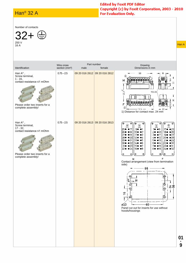
01·9
IdentificationWire cross section (mm²)
Part number Drawing Dimensions in mmmale female
Han A® , Screw terminal, 1 - 16, contact resistance ≤1 mOhm
Please order two inserts for a complete assembly!
0.75 – 2.5 09 20 016 2612 09 20 016 2812
1) Distance for contact max. 24 mm
Han A® , Screw terminal, 17 - 32, contact resistance ≤1 mOhm
Please order two inserts for a complete assembly!
0.75 – 2.5 09 20 016 2613 09 20 016 2813
Contact arrangement (view from termination side)
Panel cut out for inserts for use without hoods/housings
Han A
Han® 32 A Size 32 A
Number of contacts
32+ 250 V16 A

01·
10
IdentificationWire cross section (mm²)
Part number Drawing Dimensions in mmmale female
Han A® , Screw terminal, 1 - 16, with wire protection, contact resistance ≤1 mOhm
Please order two inserts for a complete assembly!
0.75 – 2.5 09 20 016 2614 09 20 016 2814
1) Distance for contact max. 24 mm
Han A® , Screw terminal, 17 - 32, with wire protection, contact resistance ≤1 mOhm
Please order two inserts for a complete assembly!
0.75 – 2.5 09 20 016 2615 09 20 016 2815
Contact arrangement (view from termination side)
Panel cut out for inserts for use without hoods/housings
Han A
Han® 32 A Size 32 A

01·
11
IdentificationWire cross section (mm²)
Part number Drawing Dimensions in mmmale female
Han E®, Crimp contact, gold plated contacts, contact resistance ≤1 mOhm
0.14 – 0.370.50.7511.52.54
09 33 000 611709 33 000 612209 33 000 611509 33 000 611809 33 000 611609 33 000 612309 33 000 6119
09 33 000 621709 33 000 622209 33 000 621509 33 000 621809 33 000 621609 33 000 622309 33 000 6221
Han E®, Crimp contact, silver plated contacts, contact resistance ≤1 mOhm
0.14 – 0.370.50.7511.52.534
09 33 000 612709 33 000 612109 33 000 611409 33 000 610509 33 000 610409 33 000 610209 33 000 610609 33 000 6107
09 33 000 622709 33 000 622009 33 000 621409 33 000 620509 33 000 620409 33 000 620209 33 000 620609 33 000 6207
Han A
Contacts
Technical characteristicsMaterial (contact) copper alloy
DetailsCrimping tools see chapter 90
Remarks on the crimp techniqueThe wire gauges mentioned in the catalogue refer to geometric wire gauges of cables.

01·
12
Han A
Application
Wind turbine by ENERCON with Han® 3 A – for a fast and reliable installation.Wind turbine by ENERCON with Han® 3 A – for a fast and reliable installation.

02·1
Contents Page
Han® 7 D .................................................................................................. 02.2
Han® 8 D .................................................................................................. 02.4
Han® 15-128 D ......................................................................................... 02.6
Contacts Han D® ...................................................................................... 02.14
Han DD® .................................................................................................. 02.16
Contacts Han DD® ................................................................................... 02.23
Han D/DD
Han D® / DD®
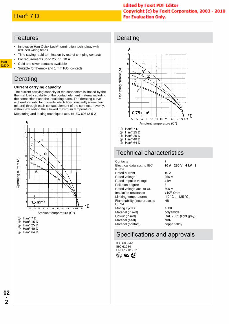
02·2
Features• Innovative Han-Quick Lock® termination technology with
reduced wiring times• Time saving rapid termination by use of crimping contacts• For requirements up to 250 V / 10 A• Gold and silver contacts available• Suitable for thermo- and 1 mm F.O. contacts
DeratingCurrent carrying capacityThe current carrying capacity of the connectors is limited by the thermal load capability of the contact element material including the connections and the insulating parts. The derating curve is therefore valid for currents which flow constantly (non-inter-mittent) through each contact element of the connector evenly, without exceeding the allowed maximum temperature.Measuring and testing techniques acc. to IEC 60512-5-2
Ope
ratin
g cu
rrent
(A)
Ambient temperature (C°)① Han® 7 D ② Han® 15 D ③ Han® 25 D ④ Han® 40 D ⑤ Han® 64 D
Derating
Ope
ratin
g cu
rrent
(A)
Ambient temperature (C°)① Han® 7 D ② Han® 15 D ③ Han® 25 D ④ Han® 40 D ⑤ Han® 64 D
Technical characteristicsContacts 7Electrical data acc. to IEC 61984
10 A 250 V 4 kV 3
Rated current 10 ARated voltage 250 VRated impulse voltage 4 kVPollution degree 3Rated voltage acc. to UL 600 VInsulation resistance ≥1010 OhmLimiting temperatures -40 °C ... 125 °CFlammability (insert) acc. to UL 94
HB
Mating cycles ≥500Material (insert) polyamideColour (insert) RAL 7032 (light grey)Material (seal) NBRMaterial (contact) copper alloy
Specifications and approvalsIEC 60664-1IEC 61984EN 175301-801
, ,
Han D/DD
Han® 7 D

02·3
IdentificationWire cross section (mm²)
Part number Drawing Dimensions in mmmale female
Han D®, Han-Quick Lock® termination, silver plated contacts, contact resistance ≤3 mOhm
only for thermoplastic hoods/housings
0.25 – 1.5 09 21 007 2632 09 21 007 2732
Contact arrangement (view from termination side)
Han D®, Crimp terminal
Please order crimp contacts separately.only for thermoplastic hoods/housings
09 21 007 3031 09 21 007 3131
Contact arrangement (view from termination side)
Han D/DD
Han® 7 D Size 3 A
Number of contacts
7+ 250 V10 A

02·4
Features• Innovative Han-Quick Lock® termination technology with
reduced wiring times• Time saving rapid termination by use of crimping contacts• Gold and silver contacts available• Insert suitable for metal hoods and housings size Han® 3 A• High density of contacts
Technical characteristicsContacts 8Electrical data acc. to IEC 61984
10 A 50 V 0.8 kV 3
Rated current 10 ARated voltage 50 VRated impulse voltage 0.8 kVPollution degree 3Rated voltage AC 50 VRated voltage DC 120 VRated voltage acc. to UL 50 VRated voltage acc. to CSA 50 VInsulation resistance ≥1010 OhmLimiting temperatures -40 °C ... 125 °CFlammability (insert) acc. to UL 94
HB
Mating cycles ≥500Material (insert) polyamideColour (insert) RAL 7032 (light grey)Material (seal) NBRMaterial (contact) copper alloy
Specifications and approvalsIEC 60664-1IEC 61984EN 175301-801
, ,
Han D/DD
Han® 8 D

02·5
IdentificationWire cross section (mm²)
Part number Drawing Dimensions in mmmale female
Han D®, Han-Quick Lock® termination, silver plated contacts, contact resistance ≤3 mOhm
for thermoplastics and metal hoods/housings
0.25 – 1.5 09 36 008 2632 09 36 008 2732
Contact arrangement (view from termination side)
Han D®, Crimp terminal
Please order crimp contacts separately.for thermoplastics and metal hoods/housings
09 36 008 3001 09 36 008 3101
Contact arrangement (view from termination side)
Han D/DD
Han® 8 D Size 3 A
Number of contacts
8~ 50 V- 120 V50 V10 A

02·6
Features• High density of contacts• For requirements up to 250 V / 10 A• Time saving rapid termination by use of crimping contacts• Gold and silver contacts available• Suitable for thermo- and 1 mm F.O. contacts
DeratingCurrent carrying capacityThe current carrying capacity of the connectors is limited by the thermal load capability of the contact element material including the connections and the insulating parts. The derating curve is therefore valid for currents which flow constantly (non-inter-mittent) through each contact element of the connector evenly, without exceeding the allowed maximum temperature.Measuring and testing techniques acc. to IEC 60512-5-2
Ope
ratin
g cu
rrent
(A)
Ambient temperature (C°)① Han® 7 D ② Han® 15 D ③ Han® 25 D ④ Han® 40 D ⑤ Han® 64 D
Derating
Ope
ratin
g cu
rrent
(A)
Ambient temperature (C°)① Han® 7 D ② Han® 15 D ③ Han® 25 D ④ Han® 40 D ⑤ Han® 64 D
Technical characteristicsContacts 15, 25, 40, 50, 64, 80, 128Electrical data acc. to IEC 61984
10 A 250 V 4 kV 3
Rated current 10 ARated voltage 250 VRated impulse voltage 4 kVPollution degree 3Rated voltage acc. to UL 600 VRated voltage acc. to CSA 600 VInsulation resistance ≥1010 OhmLimiting temperatures -40 °C ... 125 °CFlammability (insert) acc. to UL 94
HB, V 0
Mating cycles ≥500Material (insert) polyamide, polycarbonateColour (insert) RAL 7032 (light grey)Dimensions wire wrap post 1 x 1 mm, length 22 mmMaterial (contact) copper alloy
Specifications and approvalsIEC 60664-1IEC 61984EN 175301-801
, ,
DetailsHan® 40 and 64 D made of polycarbonate (flammability acc. to UL 94: V 0)
ATTENTION! Guide pins and bushes are prescribed (see chap-ter 80).
Han D/DD
Han® 15-128 D

02·7
IdentificationPart number Drawing
Dimensions in mmmale female
Han D®, Crimp terminal
Please order crimp contacts separately.
09 21 015 3001 09 21 015 3101
1) Distance for contact max. 24 mm
Han D®, Wrap terminal, contact resistance ≤3 mOhm
09 21 015 2601 09 21 015 2701
Contact arrangement (view from termination side)
Panel cut out for inserts for use without hoods/housings
Han D/DD
Han® 15 D Size 10 A
Number of contacts
15+ 250 V10 A

02·8
IdentificationPart number Drawing
Dimensions in mmmale female
Han D®, Crimp terminal
Please order crimp contacts separately.
09 21 025 3001 09 21 025 3101
1) Distance for contact max. 24 mm
Han D®, Wrap terminal, contact resistance ≤3 mOhm
09 21 025 2601 09 21 025 2701
Contact arrangement (view from termination side)
Panel cut out for inserts for use without hoods/housings
Han D/DD
Han® 25 D Size 16 A
Number of contacts
25+ 250 V10 A

02·9
IdentificationPart number Drawing
Dimensions in mmmale female
Han D®, Crimp terminal
Please order crimp contacts separately.
09 21 040 3001 09 21 040 3101
1) Distance for contact max. 21 mm
Han D®, Wrap terminal, contact resistance ≤3 mOhm
09 21 040 2601 09 21 040 2701
Contact arrangement (view from termination side)
Panel cut out for inserts for use without hoods/housings
Han D/DD
Han® 40 D Size 16 B
Number of contacts
40+ 250 V10 A

02·
10
IdentificationPart number Drawing
Dimensions in mmmale female
Han D®, Crimp terminal
Please order crimp contacts separately.Please order two inserts for a complete assem-bly!
09 21 025 3001 09 21 025 3101
1) Distance for contact max. 24 mm
Han D®, Wrap terminal, contact resistance ≤3 mOhm
Please order two inserts for a complete assem-bly!
09 21 025 2601 09 21 025 2701
Contact arrangement (view from termination side)
Panel cut out for inserts for use without hoods/housings
Han D/DD
Han® 50 D Size 32 A
Number of contacts
50+ 250 V10 A

02·
11
IdentificationPart number Drawing
Dimensions in mmmale female
Han D®, Crimp terminal
Please order crimp contacts separately.
09 21 064 3001 09 21 064 3101
1) Distance for contact max. 21 mm
Han D®, Wrap terminal, contact resistance ≤3 mOhm
09 21 064 2601 09 21 064 2701
Contact arrangement (view from termination side)
Panel cut out for inserts for use without hoods/housings
Han D/DD
Han® 64 D Size 24 B
Number of contacts
64+ 250 V10 A

02·
12
IdentificationPart number Drawing
Dimensions in mmmale female
Han D®, Crimp terminal
Please order crimp contacts separately.Please order two inserts for a complete assem-bly!
09 21 040 3001 09 21 040 3101
1) Distance for contact max. 21 mm
Han D®, Wrap terminal, contact resistance ≤3 mOhm
Please order two inserts for a complete assem-bly!
09 21 040 2601 09 21 040 2701
Contact arrangement (view from termination side)
Panel cut out for inserts for use without hoods/housings
Han D/DD
Han® 80 D Size 32 B
Number of contacts
80+ 250 V10 A

02·
13
IdentificationPart number Drawing
Dimensions in mmmale female
Han D®, Crimp terminal
Please order crimp contacts separately.Please order two inserts for a complete assem-bly!
09 21 064 3001 09 21 064 3101
1) Distance for contact max. 21 mm
Han D®, Wrap terminal, contact resistance ≤3 mOhm
Please order two inserts for a complete assem-bly!
09 21 064 2601 09 21 064 2701
Contact arrangement (view from termination side)
Panel cut out for inserts for use without hoods/housings
Han D/DD
Han® 128 D Size 48 B
Number of contacts
128+ 250 V10 A

02·
14
IdentificationWire cross section (mm²)
Part number Drawing Dimensions in mmmale female
Han D®, Crimp contact, gold plated contacts, contact resistance ≤3 mOhm
0.14 – 0.370.50.7511.52.5
09 15 000 612409 15 000 612309 15 000 612509 15 000 612209 15 000 612109 15 000 6126
09 15 000 622409 15 000 622309 15 000 622509 15 000 622209 15 000 622109 15 000 6226
Han D®, Crimp contact, silver plated contacts, contact resistance ≤3 mOhm
0.14 – 0.370.50.7511.52.5
09 15 000 610409 15 000 610309 15 000 610509 15 000 610209 15 000 610109 15 000 6106
09 15 000 620409 15 000 620309 15 000 620509 15 000 620209 15 000 620109 15 000 6206
F.O. contact
for 1 mm plastic fibre
20 10 001 321220 10 001 3213
20 10 001 3222
20 10 001 3212 + 20 10 001 3222for Han® 7 D, Han® 8 D, Han® 40 D, Han® 64 D, Han® 80 D, Han® 128 D
20 10 001 3213 + 20 10 001 3222for Han® 15 D, Han® 25 D, Han® 50 D
Han D/DD
Contacts Han D®
Technical characteristicsMaterial (contact) copper alloy
Specifications and approvalsIEC 60664-1IEC 61984
DetailsCrimping tools see chapter 90
Remarks on the crimp techniqueThe wire gauges mentioned in the catalogue refer to geometric wire gauges of cables.
Coding pinUse of the coding pin prevents incorrect mating to other connec-tors of the same type. The male pin should be omitted from the opposing cavity in the male insert.

02·
15
IdentificationWire cross section (mm²)
Part number Drawing Dimensions in mmmale female
Han D®, Han DD®, Coding pin, plastic
only for crimp terminationwith loss of one contact
09 33 000 9915
Han D/DD
Contacts Han D®
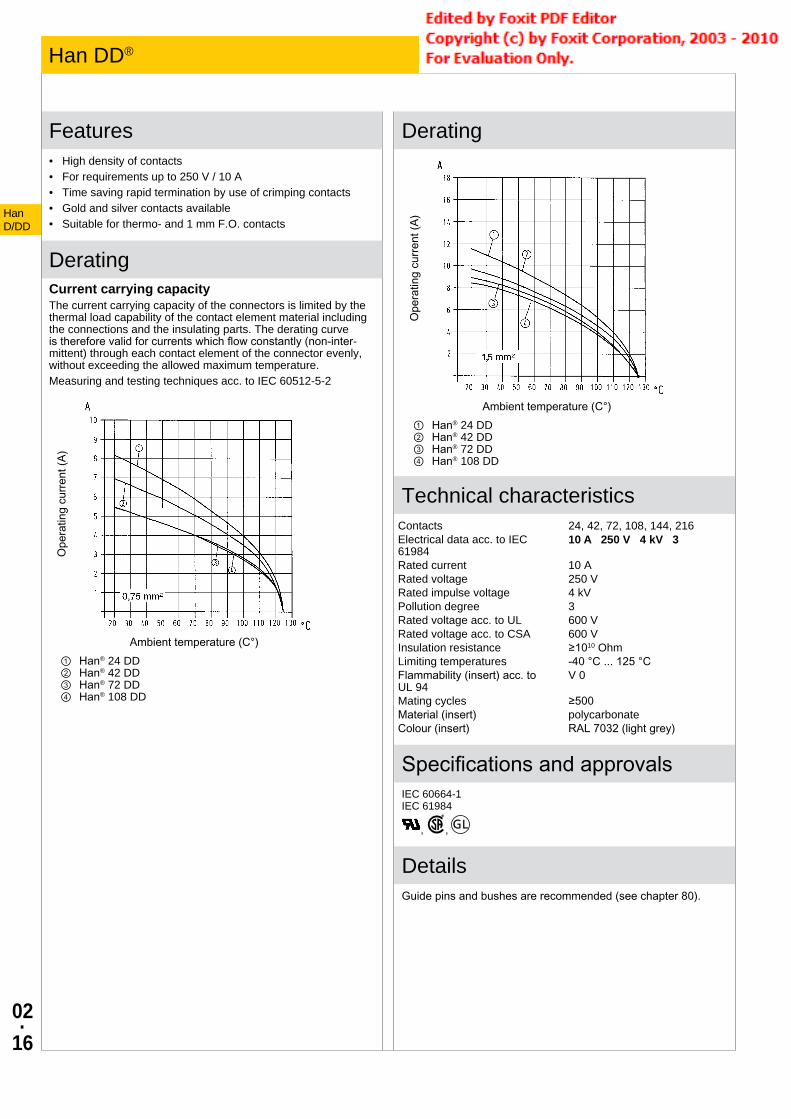
02·
16
Features• High density of contacts• For requirements up to 250 V / 10 A• Time saving rapid termination by use of crimping contacts• Gold and silver contacts available• Suitable for thermo- and 1 mm F.O. contacts
DeratingCurrent carrying capacityThe current carrying capacity of the connectors is limited by the thermal load capability of the contact element material including the connections and the insulating parts. The derating curve is therefore valid for currents which flow constantly (non-inter-mittent) through each contact element of the connector evenly, without exceeding the allowed maximum temperature.Measuring and testing techniques acc. to IEC 60512-5-2
Ope
ratin
g cu
rrent
(A)
Ambient temperature (C°)① Han® 24 DD ② Han® 42 DD ③ Han® 72 DD ④ Han® 108 DD
Derating
Ope
ratin
g cu
rrent
(A)
Ambient temperature (C°)① Han® 24 DD ② Han® 42 DD ③ Han® 72 DD ④ Han® 108 DD
Technical characteristicsContacts 24, 42, 72, 108, 144, 216Electrical data acc. to IEC 61984
10 A 250 V 4 kV 3
Rated current 10 ARated voltage 250 VRated impulse voltage 4 kVPollution degree 3Rated voltage acc. to UL 600 VRated voltage acc. to CSA 600 VInsulation resistance ≥1010 OhmLimiting temperatures -40 °C ... 125 °CFlammability (insert) acc. to UL 94
V 0
Mating cycles ≥500Material (insert) polycarbonateColour (insert) RAL 7032 (light grey)
Specifications and approvalsIEC 60664-1IEC 61984
, ,
DetailsGuide pins and bushes are recommended (see chapter 80).
Han D/DD
Han DD®

02·
17
IdentificationPart number Drawing
Dimensions in mmmale female
Han DD®, Crimp terminal
Please order crimp contacts separately.
09 16 024 3001 09 16 024 3101
1) Distance for contact max. 21 mm
Contact arrangement (view from termination side)
Panel cut out for inserts for use without hoods/housings
Han D/DD
Han® 24 DD Size 6 B
Number of contacts
24+ 250 V10 A

02·
18
IdentificationPart number Drawing
Dimensions in mmmale female
Han DD®, Crimp terminal
Please order crimp contacts separately.
09 16 042 3001 09 16 042 3101
1) Distance for contact max. 21 mm
Contact arrangement (view from termination side)
Panel cut out for inserts for use without hoods/housings
Han D/DD
Han® 42 DD Size 10 B
Number of contacts
42+ 250 V10 A

02·
19
IdentificationPart number Drawing
Dimensions in mmmale female
Han DD®, Crimp terminal
Please order crimp contacts separately.
09 16 072 3001 09 16 072 3101
1) Distance for contact max. 21 mm
Contact arrangement (view from termination side)
Panel cut out for inserts for use without hoods/housings
Han D/DD
Han® 72 DD Size 16 B
Number of contacts
72+ 250 V10 A

02·
20
IdentificationPart number Drawing
Dimensions in mmmale female
Han DD®, Crimp terminal
Please order crimp contacts separately.
09 16 108 3001 09 16 108 3101
1) Distance for contact max. 21 mm
Contact arrangement (view from termination side)
Panel cut out for inserts for use without hoods/housings
Han D/DD
Han® 108 DD Size 24 B
Number of contacts
108+ 250 V10 A

02·
21
IdentificationPart number Drawing
Dimensions in mmmale female
Han DD®, Crimp terminal, 1 - 72
Please order crimp contacts separately.Please order two inserts for a complete assem-bly!
09 16 072 3001 09 16 072 3101
1) Distance for contact max. 21 mm
Han DD®, Crimp terminal, 73 - 144
Please order crimp contacts separately.Please order two inserts for a complete assem-bly!
09 16 072 3011 09 16 072 3111
Contact arrangement (view from termination side)
Panel cut out for inserts for use without hoods/housings
Han D/DD
Han® 144 DD Size 32 B
Number of contacts
144+ 250 V10 A

02·
22
IdentificationPart number Drawing
Dimensions in mmmale female
Han DD®, Crimp terminal, 1 - 108
Please order crimp contacts separately.Please order two inserts for a complete assem-bly!
09 16 108 3001 09 16 108 3101
1) Distance for contact max. 21 mm
Han DD®, Crimp terminal, 109 - 216
Please order crimp contacts separately.Please order two inserts for a complete assem-bly!
09 16 108 3011 09 16 108 3111
Contact arrangement (view from termination side)
Panel cut out for inserts for use without hoods/housings
Han D/DD
Han® 216 DD Size 48 B
Number of contacts
216+ 250 V10 A

02·
23
IdentificationWire cross section (mm²)
Part number Drawing Dimensions in mmmale female
Han D®, Crimp contact, gold plated contacts, contact resistance ≤3 mOhm
0.14 – 0.370.50.7511.52.5
09 15 000 612409 15 000 612309 15 000 612509 15 000 612209 15 000 612109 15 000 6126
09 15 000 622409 15 000 622309 15 000 622509 15 000 622209 15 000 622109 15 000 6226
Han D®, Crimp contact, silver plated contacts, contact resistance ≤3 mOhm
0.14 – 0.370.50.7511.52.5
09 15 000 610409 15 000 610309 15 000 610509 15 000 610209 15 000 610109 15 000 6106
09 15 000 620409 15 000 620309 15 000 620509 15 000 620209 15 000 620109 15 000 6206
F.O. contact
for 1 mm plastic fibre
20 10 001 3211 20 10 001 3221
20 10 001 3211 + 20 10 001 3221
Han D®, Han DD®, Coding pin, plastic
only for crimp terminationwith loss of one contact
09 33 000 9915
Han D/DD
Contacts Han DD®
Technical characteristicsMaterial (contact) copper alloy
Specifications and approvalsIEC 60664-1IEC 61984
DetailsCrimping tools see chapter 90
Remarks on the crimp techniqueThe wire gauges mentioned in the catalogue refer to geometric wire gauges of cables.
Coding pinUse of the coding pin prevents incorrect mating to other connec-tors of the same type. The male pin should be omitted from the opposing cavity in the male insert.

02·
24
Han D/DD
Modified contact arrangements
Modified contact arrangement The connector series Han DD® and Han D® equipped with all contacts may be used for voltages up to 250 V, pollution degree 3. A modified contact loading arrangement permits use up to 500 V also in the same pollution degree.
According to DIN EN 61 984 connectors should not be coupled or decoupled under electrical load.
Series Han DD®
10 A 400 V 6 kV 3Rated current 10 A Rated voltage 400 V Rated impulse voltage 6 kV Pollution degree 3
Contact arrangement view from termination side
10 A 500 V 6 kV 3Rated current 10 A Rated voltage 500 V Rated impulse voltage 6 kV Pollution degree 3
● Working contact ○ Without contact M - Male insert F - Female insert
Series Han D®
10 A 500 V 6 kV 3Rated current 10 A Rated voltage 500 V Rated impulse voltage 6 kV Pollution degree 3
Contact arrangement view from termination side
● Working contact ○ Without contact M - Male insert F - Female insert

03·1
Contents Page
Han E® ..................................................................................................... 03.3
Han® ES/ESS .......................................................................................... 03.12
Han® EE ................................................................................................... 03.22
Han® EEE ................................................................................................ 03.29
Contacts .................................................................................................. 03.32
HanE/EE
Han E® / Han® ES/ESS/EE/EEE

03·2
HanE/EE
Modified contact arrangements Han® EE
The connector series Han® EE equipped with all contacts may be used for voltages up to 500 V ~ pollution degree 3. A modified contact loading arrangement permits use up to 1000 V ~ pollution degree also in pollution degree 3. Fully equipped connectors may also be used up to 1000 V ~ but in a lower pollution degree. See chapter 00. According to IEC 61984 connectors should not be coupled or decoupled under electrical load.
690 V Pollution degree 3Contact arrangement view from termination side
● Working contact ○ Without contact M - Male insert F - Female insert
1000 V Pollution degree 3Contact arrangement view from termination side
● Working contact ○ Without contact M - Male insert F - Female insert

03·3
Features• Covers a wide range of cross core sections• Screw termination with wire protection
DeratingCurrent carrying capacityThe current carrying capacity of the connectors is limited by the thermal load capability of the contact element material including the connections and the insulating parts. The derating curve is therefore valid for currents which flow constantly (non-inter-mittent) through each contact element of the connector evenly, without exceeding the allowed maximum temperature.Measuring and testing techniques acc. to IEC 60512-5-2
Ope
ratin
g cu
rrent
(A)
Ambient temperature (C°)① Han® 6 E ② Han® 10 E ③ Han® 16 E Han® 32 E ④ Han® 24 E Han® 48 E
Derating
Ope
ratin
g cu
rrent
(A)
Ambient temperature (C°)① Han® 6 E ② Han® 10 E ③ Han® 16 E Han® 32 E ④ Han® 24 E Han® 48 E
Technical characteristicsContacts 6, 10, 16, 24, 32, 48Electrical data acc. to IEC 61984
16 A 500 V 6 kV 3
Rated current 16 ARated voltage 500 VRated impulse voltage 6 kVPollution degree 3Rated voltage acc. to UL 600 VRated voltage acc. to CSA 600 VInsulation resistance ≥1010 OhmLimiting temperatures -40 °C ... 125 °CFlammability (insert) acc. to UL 94
V 0
Mating cycles ≥500Tightening torque 0.5 NmMaterial (insert) polycarbonateColour (insert) RAL 7032 (light grey)
Specifications and approvalsIEC 60664-1IEC 61984
, ,
DetailsInternal use in the switch cabinet in conjunction with Han-Snap® (see chapter 11)
Suitable for hoods/housings of series Han® B, Han® M, Han® EMV, Han® HPR, Han® Easy Hood (see chapter 31)
HanE/EE
Han E®

03·4
IdentificationWire cross section (mm²)
Part number Drawing Dimensions in mmmale female
Han E®, Crimp terminal
Please order crimp contacts separately.
09 33 006 2602 09 33 006 2702
1) Distance for contact max. 21 mm
Han E®, Screw terminal, with wire protection, contact resistance ≤1 mOhm
0.75 – 2.5 09 33 006 2601 09 33 006 2701
1) Distance for contact max. 21 mm
Contact arrangement (view from termination side)
Panel cut out
HanE/EE
Han E® Size 6 B
Number of contacts
6+ 500 V16 A

03·5
IdentificationWire cross section (mm²)
Part number Drawing Dimensions in mmmale female
Han E®, Crimp terminal
Please order crimp contacts separately.
09 33 010 2602 09 33 010 2702
1) Distance for contact max. 21 mm
Han E®, Screw terminal, with wire protection, contact resistance ≤1 mOhm
0.75 – 2.5 09 33 010 2601 09 33 010 2701
1) Distance for contact max. 21 mm
Contact arrangement (view from termination side)
Panel cut out
HanE/EE
Han E® Size 10 B
Number of contacts
10+ 500 V16 A

03·6
IdentificationWire cross section (mm²)
Part number Drawing Dimensions in mmmale female
Han E®, Crimp terminal
Please order crimp contacts separately.
09 33 016 2602 09 33 016 2702
1) Distance for contact max. 21 mm
Han E®, Screw terminal, with wire protection, contact resistance ≤1 mOhm
0.75 – 2.5 09 33 016 2601 09 33 016 2701
1) Distance for contact max. 21 mm
Contact arrangement (view from termination side)
Panel cut out
HanE/EE
Han E® Size 16 B
Number of contacts
16+ 500 V16 A

03·7
IdentificationWire cross section (mm²)
Part number Drawing Dimensions in mmmale female
Han E®, Crimp terminal
Please order crimp contacts separately.
09 33 024 2602 09 33 024 2702
1) Distance for contact max. 21 mm
Han E®, Screw terminal, with wire protection, contact resistance ≤1 mOhm
0.75 – 2.5 09 33 024 2601 09 33 024 2701
1) Distance for contact max. 21 mm
Contact arrangement (view from termination side)
Panel cut out
HanE/EE
Han E® Size 24 B
Number of contacts
24+ 500 V16 A

03·8
IdentificationWire cross section (mm²)
Part number Drawing Dimensions in mmmale female
Han E®, Crimp terminal, 1 - 16
Please order crimp contacts separately.Please order two inserts for a complete assembly!
09 33 016 2602 09 33 016 2702
1) Distance for contact max. 21 mm
Han E®, Crimp terminal, 17 - 32
Please order crimp contacts separately.Please order two inserts for a complete assembly!
09 33 016 2612 09 33 016 2712
Contact arrangement (view from termination side)
Panel cut out
HanE/EE
Han E® Size 32 B
Number of contacts
32+ 500 V16 A

03·9
IdentificationWire cross section (mm²)
Part number Drawing Dimensions in mmmale female
Han E®, Screw terminal, 1 - 16, with wire protection, contact resistance ≤1 mOhm
Please order two inserts for a complete assembly!
0.75 – 2.5 09 33 016 2601 09 33 016 2701
1) Distance for contact max. 21 mm
Han E®, Screw terminal, 17 - 32, with wire protection, contact resistance ≤1 mOhm
Please order two inserts for a complete assembly!
0.75 – 2.5 09 33 016 2611 09 33 016 2711
Contact arrangement (view from termination side)
Panel cut out
HanE/EE
Han E® Size 32 B

03·
10
IdentificationWire cross section (mm²)
Part number Drawing Dimensions in mmmale female
Han E®, Crimp terminal, 1 - 24
Please order crimp contacts separately.Please order two inserts for a complete assembly!
09 33 024 2602 09 33 024 2702
1) Distance for contact max. 21 mm
Han E®, Crimp terminal, 25 - 48
Please order crimp contacts separately.Please order two inserts for a complete assembly!
09 33 024 2612 09 33 024 2712
Contact arrangement (view from termination side)
Panel cut out
HanE/EE
Han E® Size 48 B
Number of contacts
48+ 500 V16 A

03·
11
IdentificationWire cross section (mm²)
Part number Drawing Dimensions in mmmale female
Han E®, Screw terminal, 1 - 24, with wire protection, contact resistance ≤1 mOhm
Please order two inserts for a complete assembly!
0.75 – 2.5 09 33 024 2601 09 33 024 2701
1) Distance for contact max. 21 mm
Han E®, Screw terminal, 25 - 48, with wire protection, contact resistance ≤1 mOhm
Please order two inserts for a complete assembly!
0.75 – 2.5 09 33 024 2611 09 33 024 2711
Contact arrangement (view from termination side)
Panel cut out
HanE/EE
Han E® Size 48 B

03·
12
Features• Reliable cage clamp termination• Han® ESS: two termination points per contact• Vibration prooved• No special tools required
DeratingCurrent carrying capacityThe current carrying capacity of the connectors is limited by the thermal load capability of the contact element material including the connections and the insulating parts. The derating curve is therefore valid for currents which flow constantly (non-inter-mittent) through each contact element of the connector evenly, without exceeding the allowed maximum temperature.Measuring and testing techniques acc. to IEC 60512-5-2
Ope
ratin
g cu
rrent
(A)
Ambient temperature (C°)① Han® 6 ES ② Han® 10 ES ③ Han® 16 ES Han® 32 ES ④ Han® 24 ES Han® 48 ES
Ope
ratin
g cu
rrent
(A)
Ambient temperature (C°)① Han® 6 ES ② Han® 10 ES ③ Han® 16 ES Han® 32 ES ④ Han® 24 ES Han® 48 ES
Derating
Ope
ratin
g cu
rrent
(A)
Ambient temperature (C°)① Han® 6 ESS ② Han® 10 ESS ③ Han® 16 ESS Han® 32 ESS ④ Han® 24 ESS Han® 48 ESS
Ope
ratin
g cu
rrent
(A)
Ambient temperature (C°)① Han® 6 ESS ② Han® 10 ESS ③ Han® 16 ESS Han® 32 ESS ④ Han® 24 ESS Han® 48 ESS
Technical characteristicsContacts 6, 10, 16, 24, 32, 48Electrical data acc. to IEC 61984
16 A 500 V 6 kV 3
Rated current 16 ARated voltage 500 VRated impulse voltage 6 kVPollution degree 3Rated voltage acc. to UL 600 VRated voltage acc. to CSA 600 VInsulation resistance ≥1010 OhmLimiting temperatures -40 °C ... 125 °CFlammability (insert) acc. to UL 94
V 0
Mating cycles ≥500Material (insert) polycarbonateColour (insert) RAL 7032 (light grey)Material (contact) copper alloy
HanE/EE
Han® ES/ESS

03·
13
Specifications and approvalsIEC 60664-1IEC 61984
, ,
DetailsInternal use in the switch cabinet in conjunction with Han-Snap® (see chapter 11)
Suitable for hoods/housings of series Han® B, Han® M, Han® EMV, Han® HPR, Han® Easy Hood (see chapter 31)
HanE/EE
Han® ES/ESS

03·
14
IdentificationWire cross section (mm²)
Part number Drawing Dimensions in mmmale female
Han® ES, Cage-clamp terminal, silver plated contacts, contact resistance ≤3 mOhm
0.14 – 2.5 09 33 006 2616 09 33 006 2716
1) Distance for contact max. 21 mm
Han® ESS, Cage-clamp terminal, silver plated contacts, contact resistance ≤3 mOhm
two terminals per contact
0.14 – 2.5 09 33 006 2672 09 33 006 2772
1) Distance for contact max. 21 mm
Contact arrangement (view from termination side)
Panel cut out
HanE/EE
Han® ES/ESS Size 6 B
Number of contacts
6+ 500 V16 A

03·
15
IdentificationWire cross section (mm²)
Part number Drawing Dimensions in mmmale female
Han® ES, Cage-clamp terminal, silver plated contacts, contact resistance ≤3 mOhm
0.14 – 2.5 09 33 010 2616 09 33 010 2716
1) Distance for contact max. 21 mm
Han® ESS, Cage-clamp terminal, silver plated contacts, contact resistance ≤3 mOhm
two terminals per contact
0.14 – 2.5 09 33 010 2672 09 33 010 2772
1) Distance for contact max. 21 mm
Contact arrangement (view from termination side)
Panel cut out
HanE/EE
Han® ES/ESS Size 10 B
Number of contacts
10+ 500 V16 A

03·
16
IdentificationWire cross section (mm²)
Part number Drawing Dimensions in mmmale female
Han® ES, Cage-clamp terminal, silver plated contacts, contact resistance ≤3 mOhm
0.14 – 2.5 09 33 016 2616 09 33 016 2716
1) Distance for contact max. 21 mm
Han® ESS, Cage-clamp terminal, silver plated contacts, contact resistance ≤3 mOhm
two terminals per contact
0.14 – 2.5 09 33 016 2672 09 33 016 2772
1) Distance for contact max. 21 mm
Contact arrangement (view from termination side)
Panel cut out
HanE/EE
Han® ES/ESS Size 16 B
Number of contacts
16+ 500 V16 A
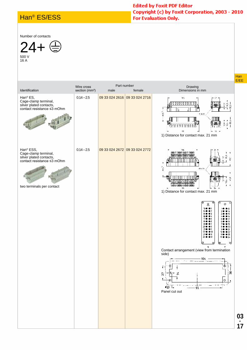
03·
17
IdentificationWire cross section (mm²)
Part number Drawing Dimensions in mmmale female
Han® ES, Cage-clamp terminal, silver plated contacts, contact resistance ≤3 mOhm
0.14 – 2.5 09 33 024 2616 09 33 024 2716
1) Distance for contact max. 21 mm
Han® ESS, Cage-clamp terminal, silver plated contacts, contact resistance ≤3 mOhm
two terminals per contact
0.14 – 2.5 09 33 024 2672 09 33 024 2772
1) Distance for contact max. 21 mm
Contact arrangement (view from termination side)
Panel cut out
HanE/EE
Han® ES/ESS Size 24 B
Number of contacts
24+ 500 V16 A

03·
18
IdentificationWire cross section (mm²)
Part number Drawing Dimensions in mmmale female
Han® ES, Cage-clamp terminal, 1 - 16, silver plated contacts, contact resistance ≤3 mOhm
Please order two inserts for a complete assembly!
0.14 – 2.5 09 33 016 2616 09 33 016 2716
1) Distance for contact max. 21 mm
Han® ES, Cage-clamp terminal, 17 - 32, silver plated contacts, contact resistance ≤3 mOhm
Please order two inserts for a complete assembly!
0.14 – 2.5 09 33 016 2626 09 33 016 2726
Contact arrangement (view from termination side)
Panel cut out
HanE/EE
Han® ES/ESS Size 32 B
Number of contacts
32+ 500 V16 A

03·
19
IdentificationWire cross section (mm²)
Part number Drawing Dimensions in mmmale female
Han® ESS, Cage-clamp terminal, silver plated contacts, contact resistance ≤3 mOhm
Please order two inserts for a complete assembly!
0.14 – 2.5 09 33 016 2672 09 33 016 2772
1) Distance for contact max. 21 mm
Contact arrangement (view from termination side)
Panel cut out
HanE/EE
Han® ES/ESS Size 32 B

03·
20
IdentificationWire cross section (mm²)
Part number Drawing Dimensions in mmmale female
Han® ES, Cage-clamp terminal, 1 - 24, silver plated contacts, contact resistance ≤3 mOhm
Please order two inserts for a complete assembly!
0.14 – 2.5 09 33 024 2616 09 33 024 2716
1) Distance for contact max. 21 mm
Han® ES, Cage-clamp terminal, 25 - 48, silver plated contacts, contact resistance ≤3 mOhm
Please order two inserts for a complete assembly!
0.14 – 2.5 09 33 024 2626 09 33 024 2726
Contact arrangement (view from termination side)
Panel cut out
HanE/EE
Han® ES/ESS Size 48 B
Number of contacts
48+ 500 V16 A

03·
21
IdentificationWire cross section (mm²)
Part number Drawing Dimensions in mmmale female
Han® ESS, Cage-clamp terminal, silver plated contacts, contact resistance ≤3 mOhm
Please order two inserts for a complete assembly!
0.14 – 2.5 09 33 024 2672 09 33 024 2772
1) Distance for contact max. 21 mm
Contact arrangement (view from termination side)
Panel cut out
HanE/EE
Han® ES/ESS Size 48 B

03·
22
Features• Higher density of crimping contacts• Coded insert• Gold and silver contacts available
DeratingCurrent carrying capacityThe current carrying capacity of the connectors is limited by the thermal load capability of the contact element material including the connections and the insulating parts. The derating curve is therefore valid for currents which flow constantly (non-inter-mittent) through each contact element of the connector evenly, without exceeding the allowed maximum temperature.Measuring and testing techniques acc. to IEC 60512-5-2
Ope
ratin
g cu
rrent
(A)
Ambient temperature (C°)① Han® 10 EE ② Han® 18 EE ③ Han® 32 EE Han® 64 EE ④ Han® 46 EE Han® 92 EE
Ope
ratin
g cu
rrent
(A)
Ambient temperature (C°)① Han® 10 EE ② Han® 18 EE ③ Han® 32 EE Han® 64 EE ④ Han® 46 EE Han® 92 EE
Technical characteristicsContacts 10, 18, 32, 46, 64, 92Electrical data acc. to IEC 61984
16 A 500 V 6 kV 3
Rated current 16 ARated voltage 500 VRated impulse voltage 6 kVPollution degree 3Rated voltage acc. to UL 600 VRated voltage acc. to CSA 600 VInsulation resistance ≥1010 OhmLimiting temperatures -40 °C ... 125 °CFlammability (insert) acc. to UL 94
V 0
Mating cycles ≥500Material (insert) polycarbonateColour (insert) RAL 7032 (light grey)
Specifications and approvalsIEC 60664-1IEC 61984
, ,
DetailsInternal use in the switch cabinet in conjunction with Han-Snap® (see chapter 11)
Suitable for hoods/housings of series Han® B, Han® M, Han® EMV, Han® HPR, Han® Easy Hood (see chapter 31)
HanE/EE
Han® EE

03·
23
IdentificationPart number Drawing
Dimensions in mmmale female
Han® EE, Crimp terminal
Please order crimp contacts separately.
09 32 010 3001 09 32 010 3101
1) Distance for contact max. 21 mm
Contact arrangement (view from termination side)
Panel cut out
HanE/EE
Han® EE Size 6 B
Number of contacts
10+ 500 V16 A

03·
24
IdentificationPart number Drawing
Dimensions in mmmale female
Han® EE, Crimp terminal
Please order crimp contacts separately.
09 32 018 3001 09 32 018 3101
1) Distance for contact max. 21 mm
Contact arrangement (view from termination side)
Panel cut out
HanE/EE
Han® EE Size 10 B
Number of contacts
18+ 500 V16 A

03·
25
IdentificationPart number Drawing
Dimensions in mmmale female
Han® EE, Crimp terminal
Please order crimp contacts separately.
09 32 032 3001 09 32 032 3101
1) Distance for contact max. 21 mm
Contact arrangement (view from termination side)
Panel cut out
HanE/EE
Han® EE Size 16 B
Number of contacts
32+ 500 V16 A

03·
26
IdentificationPart number Drawing
Dimensions in mmmale female
Han® EE, Crimp terminal
Please order crimp contacts separately.
09 32 046 3001 09 32 046 3101
1) Distance for contact max. 21 mm
Contact arrangement (view from termination side)
Panel cut out
HanE/EE
Han® EE Size 24 B
Number of contacts
46+ 500 V16 A

03·
27
IdentificationPart number Drawing
Dimensions in mmmale female
Han® EE, Crimp terminal, 1 - 32
Please order crimp contacts separately.Please order two inserts for a complete assem-bly!
09 32 032 3001 09 32 032 3101
1) Distance for contact max. 21 mm
Han® EE, Crimp terminal, 33 - 64
Please order crimp contacts separately.Please order two inserts for a complete assem-bly!
09 32 032 3011 09 32 032 3111
Contact arrangement (view from termination side)
Panel cut out
HanE/EE
Han® EE Size 32 B
Number of contacts
64+ 500 V16 A

03·
28
IdentificationPart number Drawing
Dimensions in mmmale female
Han® EE, Crimp terminal, 1 - 46
Please order crimp contacts separately.Please order two inserts for a complete assem-bly!
09 32 046 3001 09 32 046 3101
1) Distance for contact max. 21 mm
Han® EE, Crimp terminal, 47 - 92
Please order crimp contacts separately.Please order two inserts for a complete assem-bly!
09 32 046 3011 09 32 046 3111
Contact arrangement (view from termination side)
Panel cut out
HanE/EE
Han® EE Size 48 B
Number of contacts
92+ 500 V16 A

03·
29
Features• Highest density of crimping contacts• Coded insert• Gold and silver contacts available
DeratingCurrent carrying capacityThe current carrying capacity of the connectors is limited by the thermal load capability of the contact element material including the connections and the insulating parts. The derating curve is therefore valid for currents which flow constantly (non-inter-mittent) through each contact element of the connector evenly, without exceeding the allowed maximum temperature.Measuring and testing techniques acc. to IEC 60512-5-2
Ope
ratin
g cu
rrent
(A)
Ambient temperature (C°)① Han® 64 EEE / 1.5 mm² ② Han® 64 EEE / 2.5 mm² ③ Han® 64 EEE / 4 mm² ④ Han® 40 EEE / 1.5 mm² ⑤ Han® 40 EEE / 2.5 mm²
Technical characteristicsContacts 40, 64Electrical data acc. to IEC 61984
16 A 500 V 6 kV 3
Rated current 16 ARated voltage 500 VRated impulse voltage 6 kVPollution degree 3Insulation resistance ≥1010 OhmLimiting temperatures -40 °C ... 125 °CFlammability (insert) acc. to UL 94
V 0
Mating cycles ≥500Material (insert) polycarbonateColour (insert) RAL 7032 (light grey)
Specifications and approvalsIEC 60664-1IEC 61984
DetailsInternal use in the switch cabinet in conjunction with Han-Snap® (see chapter 11)
Suitable for hoods/housings of series Han® B, Han® M, Han® EMV, Han® HPR, Han® Easy Hood (see chapter 31)
HanE/EE
Han® EEE

03·
30
IdentificationPart number Drawing
Dimensions in mmmale female
Han® EEE, Crimp terminal
Please order crimp contacts separately.
09 32 040 3001 09 32 040 3101
1) Distance for contact max. 21 mm
Contact arrangement (view from termination side)
Panel cut out
HanE/EE
Han® EEE Size 16 B
Number of contacts
40+ 500 V16 A

03·
31
IdentificationPart number Drawing
Dimensions in mmmale female
Han® EEE, Crimp terminal
Please order crimp contacts separately.
09 32 064 3001 09 32 064 3101
1) Distance for contact max. 21 mm
Contact arrangement (view from termination side)
Panel cut out
HanE/EE
Han® EEE Size 24 B
Number of contacts
64+ 500 V16 A

03·
32
IdentificationWire cross section (mm²)
Part number Drawing Dimensions in mmmale female
Han E®, Crimp contact, gold plated contacts, contact resistance ≤1 mOhm
0.14 – 0.370.50.7511.52.54
09 33 000 611709 33 000 612209 33 000 611509 33 000 611809 33 000 611609 33 000 612309 33 000 6119
09 33 000 621709 33 000 622209 33 000 621509 33 000 621809 33 000 621609 33 000 622309 33 000 6221
Han E®, Crimp contact, silver plated contacts, contact resistance ≤1 mOhm
0.14 – 0.370.50.7511.52.534
09 33 000 612709 33 000 612109 33 000 611409 33 000 610509 33 000 610409 33 000 610209 33 000 610609 33 000 6107
09 33 000 622709 33 000 622009 33 000 621409 33 000 620509 33 000 620409 33 000 620209 33 000 620609 33 000 6207
HanE/EE
Contacts
Technical characteristicsMaterial (contact) copper alloy
Specifications and approvalsIEC 60664-1IEC 61984
DetailsCrimping tools see chapter 90
Remarks on the crimp techniqueThe wire gauges mentioned in the catalogue refer to geometric wire gauges of cables.
Coding pinUse of the coding pin prevents incorrect mating to other connec-tors of the same type. The male pin should be omitted from the opposing cavity in the male insert.