Harmonic Distortion Impact On Electro-Mechanical And ... Distortion Impact On Electro-Mechanical And...
6
Harmonic Distortion Impact On Electro-Mechanical And Digital Protection Relays A. Medina, F. Martínez-Cárdenas Facultad de Ingeniería Eléctrica, División de Estudios de Posgrado Universidad Michoacana de San Nicolás de Hidalgo Edificio de la División del Posgrado de Ingeniería Eléctrica, Ciudad Universitaria, 58030 Morelia, Michoacán, MEXICO http://faraday.fie.umich.mx Abstract: - Established knowledge on specialized literature has shown that harmonic distortion present on voltage and current waveforms adversely affects the behaviour of electric devices including protection systems, resulting in their miss-operation or wrong operation. However, literature related to these topics normally presents studies conducted on electro-mechanical relays and less frequently on static relays; there is not much information available on the digital protection systems behavior under distorted waveforms conditions. This contribution details the results of harmonic tests conducted to three different relay generations and shows that harmonic distortion does not adversely affect the behaviour of modern digital relays in contrast with stablished knowledge found on specialized literature. Key-Words: - Digital relays, electro-mechanical relays, harmonic distortion, protection relays, static relays. 1 Introduction Widespread experience and knowledge indicate that electrical power systems require protection due to the different operation conditions appearing on each network component. These conditions can exceed normal limits of devices and may cause discontinuity on the service, damage to the electric equipment or injuries to people. That is the reason behind the evolution and development of protection devices; a complete theory around protection systems area has been developed [1-2]. The first protection relays were designed based on electromagnetic theory, resulting on the electro- mechanical relays which constituted the first generation of protective devices. These protection devices worked mainly using the magnitude of voltages or currents or both to generate a mechanical movement to operate a switch, which in turn, gives an actuating signal to the main breaker with the purpose of disconnecting the power system element exposed to abnormal conditions. This first generation of protective devices were thought to work under purely sinusoidal conditions. As expected, under these operation conditions correctly operated, but with the proliferation of nonlinear loads a new problem appeared on scene: harmonic distortion. When a nonlinear load is connected to the power system, harmonic distortion appears mainly in current waveforms. However, it is also present, at a lesser extent, in voltage waveforms. It is well documented that harmonic distortion generates different adverse effects on power system components, e.g. heating, saturation, vibration, etc [3]. In general an abnormal operation condition can be tolerated in some cases with the appropriate selection of the device ratings and in some others with the use of corrective measures, such as elimination or attenuation of harmonics. Since the inherent design of electro-mechanical relays assume a purely sinusoidal wave for their proper operation, the presence of harmonic distortion on voltage or current waveforms results on wrong or miss-operation of this type of protection systems, as documented in the open literature, even though detailed studies are seldomly available [4-6]. There is no documented information on the impact of harmonic distortion of voltage and current waveforms on static relays neither on modern digital protection relays. This contribution describes the results of a set of different tests carried-out on three different relays; each of them representing one of the three generations of protection devices; electro-mechanical, static and modern digital relays, respectively. The results and conclusions presented in this contribution establish a general panorama about the impact of harmonic distortion on different generations of protection relays. Proceedings of the 5th WSEAS Int. Conf. on Instrumentation, Measurement, Circuits and Systems, Hangzhou, China, April 16-18, 2006 (pp322-327)
Transcript of Harmonic Distortion Impact On Electro-Mechanical And ... Distortion Impact On Electro-Mechanical And...
Harmonic Distortion Impact On Electro-Mechanical And Digital Protection Relays
A. Medina, F. Martínez-Cárdenas
Facultad de Ingeniería Eléctrica, División de Estudios de Posgrado
Universidad Michoacana de San Nicolás de Hidalgo Edificio de la División del Posgrado de Ingeniería Eléctrica, Ciudad Universitaria, 58030
Morelia, Michoacán, MEXICO
http://faraday.fie.umich.mx
Abstract: - Established knowledge on specialized literature has shown that harmonic distortion present on voltage and current waveforms adversely affects the behaviour of electric devices including protection systems, resulting in their miss-operation or wrong operation. However, literature related to these topics normally presents studies conducted on electro-mechanical relays and less frequently on static relays; there is not much information available on the digital protection systems behavior under distorted waveforms conditions. This contribution details the results of harmonic tests conducted to three different relay generations and shows that harmonic distortion does not adversely affect the behaviour of modern digital relays in contrast with stablished knowledge found on specialized literature. Key-Words: - Digital relays, electro-mechanical relays, harmonic distortion, protection relays, static relays. 1 Introduction Widespread experience and knowledge indicate that electrical power systems require protection due to the different operation conditions appearing on each network component. These conditions can exceed normal limits of devices and may cause discontinuity on the service, damage to the electric equipment or injuries to people. That is the reason behind the evolution and development of protection devices; a complete theory around protection systems area has been developed [1-2].
The first protection relays were designed based on electromagnetic theory, resulting on the electro-mechanical relays which constituted the first generation of protective devices. These protection devices worked mainly using the magnitude of voltages or currents or both to generate a mechanical movement to operate a switch, which in turn, gives an actuating signal to the main breaker with the purpose of disconnecting the power system element exposed to abnormal conditions. This first generation of protective devices were thought to work under purely sinusoidal conditions. As expected, under these operation conditions correctly operated, but with the proliferation of nonlinear loads a new problem appeared on scene: harmonic distortion.
When a nonlinear load is connected to the power system, harmonic distortion appears mainly in current waveforms. However, it is also present, at a lesser extent, in voltage waveforms. It is well documented
that harmonic distortion generates different adverse effects on power system components, e.g. heating, saturation, vibration, etc [3]. In general an abnormal operation condition can be tolerated in some cases with the appropriate selection of the device ratings and in some others with the use of corrective measures, such as elimination or attenuation of harmonics.
Since the inherent design of electro-mechanical relays assume a purely sinusoidal wave for their proper operation, the presence of harmonic distortion on voltage or current waveforms results on wrong or miss-operation of this type of protection systems, as documented in the open literature, even though detailed studies are seldomly available [4-6]. There is no documented information on the impact of harmonic distortion of voltage and current waveforms on static relays neither on modern digital protection relays.
This contribution describes the results of a set of different tests carried-out on three different relays; each of them representing one of the three generations of protection devices; electro-mechanical, static and modern digital relays, respectively. The results and conclusions presented in this contribution establish a general panorama about the impact of harmonic distortion on different generations of protection relays.
Proceedings of the 5th WSEAS Int. Conf. on Instrumentation, Measurement, Circuits and Systems, Hangzhou, China, April 16-18, 2006 (pp322-327)
2 Protection relay generations Since the first use of protection devices until the present time, protection systems can be classified in three main generations: 1) Electro-mechanical or electromagnetic relays, 2) Static Relays and 3) Digital relays.
Electro-mechanical or electromagnetic relays are those whose physical construction document most of protection systems theory books [1-2] and are based on an actuating coil that receive an induced magnitude of voltage or current, to generate a mechanical movement for the instantaneous or delayed contact operation. These type of protection relays were not designed with a processing signal unit and the inducing magnitude actuates directly, without any previous conditioning. Although these relays were not designed with a signal conditioning unit included, results presented on section IV shows that their inductive nature generate a natural low-pass filter which attenuates high order harmonics. However, low-order harmonics and the dc component affect the relay operation, as documented in the open literature [4-6]. In these relays, the operation curves or operating principles are the result of their physical construction.
With the incorporation of electronics on protection relays, it was possible to implement signal processing stages to attenuate or reject undesired frequency components and make the relay operate with only fundamental frequency components. On static relays the filtering stages were designed based on analog electronics and the operation principles were implemented with available electronic technologies such as analog, digital discrete, or simple programmable digital systems. The use of digital electronics on static relays was mainly oriented to display measurements or operation states, to generate operation curves or to execute part of the operation logic. At this stage, the signal processing was completely analog and therefore with the disadvantages of slowness, low precision, and noise sensitivity associated to analog filtering.
Once programmable digital systems became suitable enough for digital signal processing applications, full digital relays became available. These type of relays just make use of an analog pre-filtering stage, commonly constituted by a low-pass filter to eliminate the dc and high frequency components, avoiding aliasing effect during digitalization of voltage or current signals. Subsequent signal processing was fully digital and was carried-out with fast, high precision, noise immune, advanced algorithms to extract the system frequency component and to generate the operation principles by means of mathematical or logical
expressions. These type of relays can incorporate different protection functions on a single unit, several measurement, control or registering functions, in addition to having multiple analog input channels and multiple programmable digital inputs and outputs. Early electro-mechanical relays and static relays are still in use and in many situations work together with digital relays. At present, however, it is more common the use of modern digital protection relays due to the operation advantages described previously. In spite of the apparent superiority of digital protection relays, the current open literature on protection relays [1-2] is based principally on electro-mechanical relays and documents miss-operation of protection systems in the presence of harmonic distortion [4-6]. However, the open literature does not establish if the arguments are still valid for modern digital protection relays. With the purpose of extending the current knowledge on the harmonic distortion impact to modern digital protection relays, different set of tests are reported in this contribution with three different protection relays representing, each of them, a relay generation (electro-mechanical, static and digital, respectively). The set of tests conducted are detailed in Section III and the results presented in Section IV. 3 Tests procedure A set of tests were designed with the purpose of testing the three generations of relays (electro-mechanical, static and modern digital) under the presence of harmonic distortion on measured signals. Since there are many types of protection relays and protection functions and some of them use voltage, current or both as input signals, and taking into account that each generation of relays applies the same processing technique to all the input signals, independently of the protection function, thus it is enough to take a representative protection function to be used to evaluate the protection system behavior under the presence of harmonic distortion. The protection function selected to carry-out the harmonic tests is the time-overcurrent or inverse time overcurrent function (function number 51, according to the standard C37.2 [7]). This function was selected because is one of the most commonly used to protect different power system elements.
To conduct the necessary tests to evaluate the relays behavior under the presence of harmonic distortion, an electro-magnetic transient simulator PSCAD/EMTDC [8] was used to simulate and generate the necessary signals to be applied to the relay. This simulator has the option of generating an output file with the results of the simulation in the
Proceedings of the 5th WSEAS Int. Conf. on Instrumentation, Measurement, Circuits and Systems, Hangzhou, China, April 16-18, 2006 (pp322-327)
COMTRADE standard format [9]. The file with the results of the simulation is imported with the software of a relay test equipment [10], and sent to each relay under test [11-13]. The relay test equipment can measure the operation time for each conducted test. 3.1 Tests without harmonic distortion To evaluate the relay behavior under the presence of harmonic distortion, a reference study consisting on the relay behavior without harmonic distortion was selected. To test the relay behavior without harmonic distortion on the current waveforms it was necessary to create a set of test signals with different levels of fundamental frequency current waveforms, such as the waveform shown on Fig. 1.
It can be seen from Fig. 1 that a sinusoidal three phase current waveform is created with two sections having different amplitudes. The first section has a fixed amplitude of 0.5 A rms (below the pickup setting of the time-overcurrent relay, in this case 1 A rms) and the second section will take different values of amplitude from 1.5 to 10 A rms on each test. These values must be above the pickup setting of time-overcurrent relay in order to trip the relay. The relay operation time is measured for each amplitude value of the second section. The operation time is measured from the point where the waveform changes from section 1 to section 2 (when the pickup is reached for the first time), to the time when the relay tripping occurs.
0 0.02 0.04 0.06 0.08 0.1 0.12 0.14 0.16 0.18 0.2-5
0
5
ia (A
mps
) Section 1 Section 2
0 0.02 0.04 0.06 0.08 0.1 0.12 0.14 0.16 0.18 0.2-5
0
5
ib (A
mps
)
0 0.02 0.04 0.06 0.08 0.1 0.12 0.14 0.16 0.18 0.2-5
0
5
ic (A
mps
)
0 0.02 0.04 0.06 0.08 0.1 0.12 0.14 0.16 0.18 0.2-5
0
5
iabc
(Am
ps)
time (seg) Fig. 1. Current waveforms without harmonic distortion.
The results obtained with the tests described
above are used to build a relay operation curve. If these tests are repeated with different values of the time dial setting, it is possible to build a complete family of inverse time curves. These tests without harmonic distortion serve as a reference to compare the results obtained adding harmonic distortion to the current waveforms.
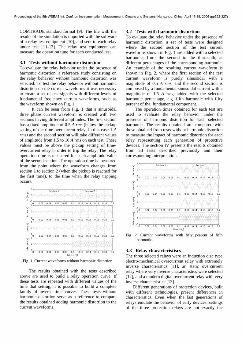
3.2 Tests with harmonic distortion To evaluate the relay behavior under the presence of harmonic distortion, a set of tests were designed where the second section of the test current waveforms shown in Fig. 1 are added with a selected harmonic, from the second to the thirteenth, at different percentages of the corresponding harmonic. An example of the resulting current waveform is shown in Fig. 2, where the first section of the test current waveform is purely sinusoidal with a magnitude of 0.5 A rms, and the second section is composed by a fundamental sinusoidal current with a magnitude of 1.5 A rms, added with the selected harmonic percentage, e.g. fifth harmonic with fifty percent of the fundamental component.
The operation times obtained for each test are used to evaluate the relay behavior under the presence of harmonic distortion for each selected harmonic. The results obtained are compared with those obtained from tests without harmonic distortion to measure the impact of harmonic distortion for each relay representing each generation of protective devices. The section IV presents the results obtained from all tests described previously and their corresponding interpretation.
0 0.02 0.04 0.06 0.08 0.1 0.12 0.14 0.16 0.18 0.2-5
0
5
ia (A
mps
) Section 1 Section 2
0 0.02 0.04 0.06 0.08 0.1 0.12 0.14 0.16 0.18 0.2-5
0
5
ib (A
mps
)
0 0.02 0.04 0.06 0.08 0.1 0.12 0.14 0.16 0.18 0.2-5
0
5
ic (A
mps
)
0 0.02 0.04 0.06 0.08 0.1 0.12 0.14 0.16 0.18 0.2-5
0
5
iabc
(Am
ps)
time (seg) Fig. 2. Current waveforms with fifty percent of fifth
harmonic. 3.3 Relay characteristiscs The three selected relays were an induction disc type electro-mechanical overcurrrent relay with extremely inverse characteristics [11], an static overcurrent relay where very inverse characteristics were selected [12], and a modern digital overcurrent relay with very inverse characteristics [13].
Different generations of protection devices, built with different technologies, present differences in characteristics. Even when the last generations of relays emulate the behavior of early devices, settings of the three protection relays are not exactly the
Proceedings of the 5th WSEAS Int. Conf. on Instrumentation, Measurement, Circuits and Systems, Hangzhou, China, April 16-18, 2006 (pp322-327)
same, as shown in Section IV. This does not represent a problem since the evaluation of harmonic distortion impact on each relay is made by comparing the reference relay behavior without harmonic distortion with the results generated on itself when harmonic distortion is added to the voltage or current signals. 4 Effect on relay operation In this section the results from the tests conducted on each relay are presented and analyzed separately to finally compare the results among the three protection relays and establish the conclusions. 4.1 Electro-mechanical relay The electro-mechanical relay selected to represent the first generation of protection devices is an overcurrent relay with protection functions 50 (instantaneous) and 51 (inverse time) and with extremely inverse characteristics in the case of function 51.
The tests were conducted using function 51, so function 50 was disabled. The selected relay adjustments were a time delay of 0.5s and a tap of 1 A rms (which corresponds to a 1 A rms pickup setting according to the relay’s manufacturer literature).
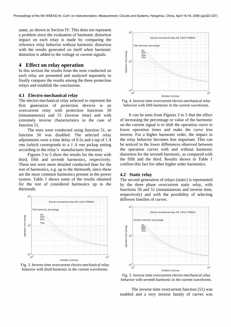
Figures 3 to 5 show the results for the tests with third, fifth and seventh harmonics, respectively. These test were more detailed conducted than for the rest of harmonics, e.g. up to the thirteenth, since these are the most common harmonics present in the power system. Table 1 shows some of the results obtained for the rest of considered harmonics up to the thirteenth.
100 101102
103
104
Multiple of pickup
Ope
ratio
n tim
e (m
seg)
Third harmonic percentage
0%25%50%75%
Electro-mechanical relay GE 12IAC77B805A
Fig. 3. Inverse time overcurrent electro-mechanical relay behavior with third harmonic in the current waveforms.
100 101102
103
104
Multiple of pickup
Ope
ratio
n tim
e (m
seg)
Fifth harmonic percentage
0%25%50%75%
Electro-mechanical relay GE 12IAC77B805A
Fig. 4. Inverse time overcurrent electro-mechanical relay behavior with fifth harmonic in the current waveforms.
It can be seen from Figures 3 to 5 that the effect
of increasing the percentage or value of the harmonic on the current signal is to shift the operation curve to lower operation times and make the curve less inverse. For a higher harmonic order, the impact in the relay behavior becomes less important. This can be noticed in the lower differences observed between the operation curves with and without harmonic distortion for the seventh harmonic, as compared with the fifth and the third. Results shown in Table 1 confirm this fact for other higher order harmonics. 4.2 Static relay The second generation of relays (static) is represented by the three phase overcurrent static relay, with functions 50 and 51 (instantaneous and inverse time, respectively) and with the possibility of selecting different families of curves.
100 101102
103
104
Multiple of pickup
Ope
ratio
n tim
e (m
seg)
Seventh harmonic percentage
0%25%50%75%
Electro-mechanical relay GE 12IAC77B805A
Fig. 5. Inverse time overcurrent electro-mechanical relay
behavior with seventh harmonic in the current waveforms.
The inverse time overcurrent function (51) was enabled and a very inverse family of curves was
Proceedings of the 5th WSEAS Int. Conf. on Instrumentation, Measurement, Circuits and Systems, Hangzhou, China, April 16-18, 2006 (pp322-327)
selected. A time delay of 0.5 s and a current pickup of 1 A rms were chosen.
As it can be seen on Figs. 1 and 2, the three phase current signals are symmetrical in amplitude (equal amplitudes for phase a, b and c) and in phase (phase shift of 120 degrees between phases a, b and c), which means that no unbalanced conditions on three phase current signals are present. Further studies will include unbalanced conditions.
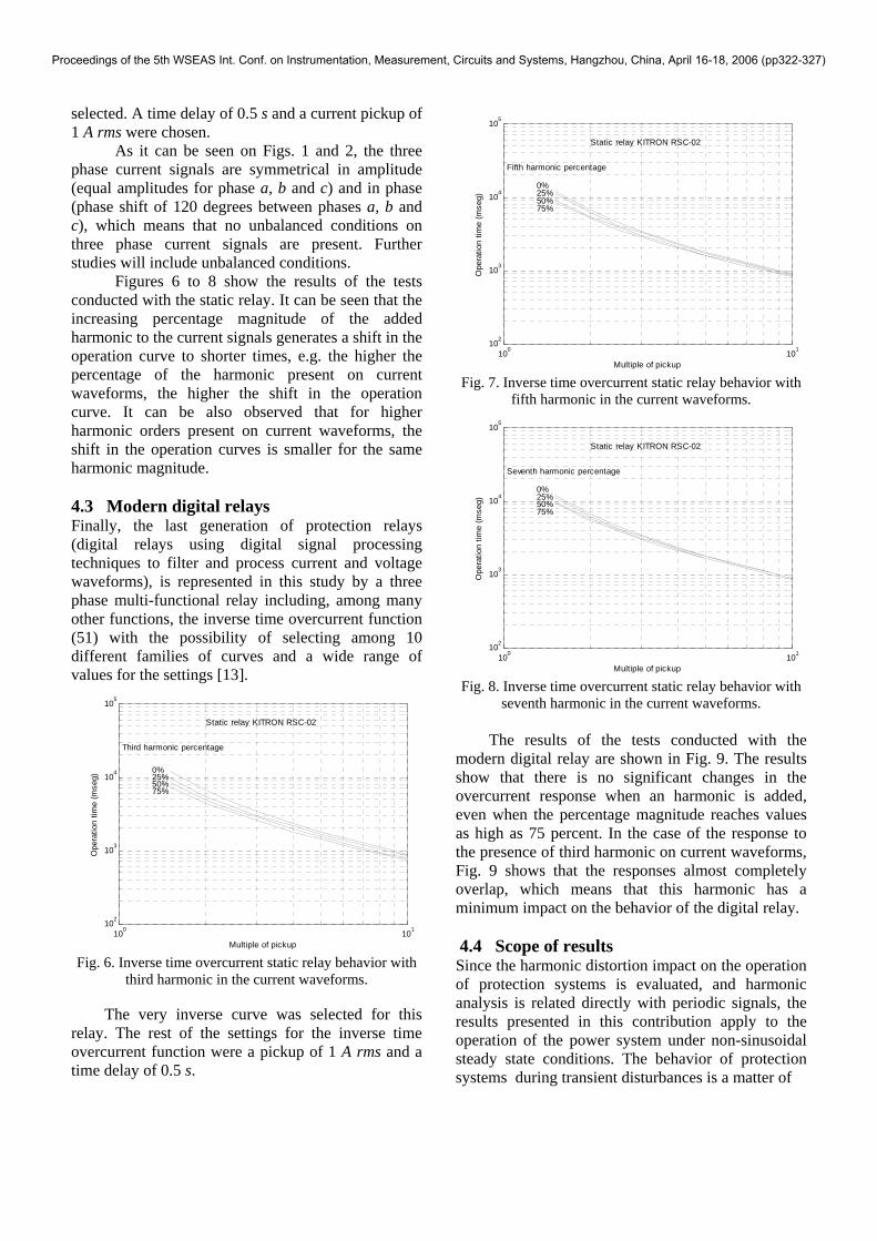
Figures 6 to 8 show the results of the tests conducted with the static relay. It can be seen that the increasing percentage magnitude of the added harmonic to the current signals generates a shift in the operation curve to shorter times, e.g. the higher the percentage of the harmonic present on current waveforms, the higher the shift in the operation curve. It can be also observed that for higher harmonic orders present on current waveforms, the shift in the operation curves is smaller for the same harmonic magnitude. 4.3 Modern digital relays Finally, the last generation of protection relays (digital relays using digital signal processing techniques to filter and process current and voltage waveforms), is represented in this study by a three phase multi-functional relay including, among many other functions, the inverse time overcurrent function (51) with the possibility of selecting among 10 different families of curves and a wide range of values for the settings [13].
100 101102
103
104
105
Multiple of pickup
Ope
ratio
n tim
e (m
seg)
Third harmonic percentage
0%25%50%75%
Static relay KITRON RSC-02
Fig. 6. Inverse time overcurrent static relay behavior with
third harmonic in the current waveforms.
The very inverse curve was selected for this relay. The rest of the settings for the inverse time overcurrent function were a pickup of 1 A rms and a time delay of 0.5 s.
100 101102
103
104
105
Multiple of pickup
Ope
ratio
n tim
e (m
seg)
Fifth harmonic percentage
0%25%50%75%
Static relay KITRON RSC-02
Fig. 7. Inverse time overcurrent static relay behavior with
fifth harmonic in the current waveforms.
100 101102
103
104
105
Multiple of pickup
Ope
ratio
n tim
e (m
seg)
Seventh harmonic percentage
0%25%50%75%
Static relay KITRON RSC-02
Fig. 8. Inverse time overcurrent static relay behavior with
seventh harmonic in the current waveforms.
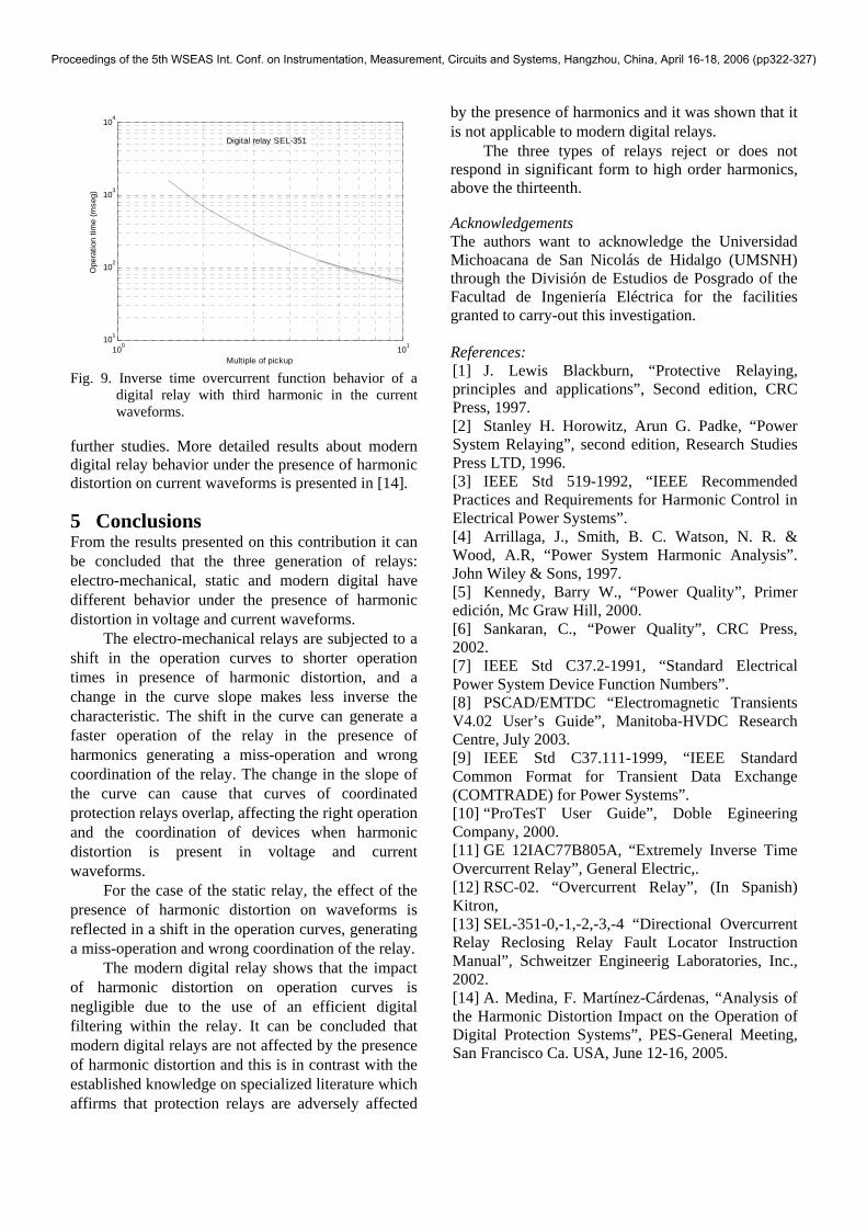
The results of the tests conducted with the modern digital relay are shown in Fig. 9. The results show that there is no significant changes in the overcurrent response when an harmonic is added, even when the percentage magnitude reaches values as high as 75 percent. In the case of the response to the presence of third harmonic on current waveforms, Fig. 9 shows that the responses almost completely overlap, which means that this harmonic has a minimum impact on the behavior of the digital relay. 4.4 Scope of results Since the harmonic distortion impact on the operation of protection systems is evaluated, and harmonic analysis is related directly with periodic signals, the results presented in this contribution apply to the operation of the power system under non-sinusoidal steady state conditions. The behavior of protection systems during transient disturbances is a matter of
Proceedings of the 5th WSEAS Int. Conf. on Instrumentation, Measurement, Circuits and Systems, Hangzhou, China, April 16-18, 2006 (pp322-327)
100 101101
102
103
104
Multiple of pickup
Ope
ratio
n tim
e (m
seg)
Digital relay SEL-351
Fig. 9. Inverse time overcurrent function behavior of a
digital relay with third harmonic in the current waveforms.
further studies. More detailed results about modern digital relay behavior under the presence of harmonic distortion on current waveforms is presented in [14]. 5 Conclusions From the results presented on this contribution it can be concluded that the three generation of relays: electro-mechanical, static and modern digital have different behavior under the presence of harmonic distortion in voltage and current waveforms.
The electro-mechanical relays are subjected to a shift in the operation curves to shorter operation times in presence of harmonic distortion, and a change in the curve slope makes less inverse the characteristic. The shift in the curve can generate a faster operation of the relay in the presence of harmonics generating a miss-operation and wrong coordination of the relay. The change in the slope of the curve can cause that curves of coordinated protection relays overlap, affecting the right operation and the coordination of devices when harmonic distortion is present in voltage and current waveforms.
For the case of the static relay, the effect of the presence of harmonic distortion on waveforms is reflected in a shift in the operation curves, generating a miss-operation and wrong coordination of the relay.
The modern digital relay shows that the impact of harmonic distortion on operation curves is negligible due to the use of an efficient digital filtering within the relay. It can be concluded that modern digital relays are not affected by the presence of harmonic distortion and this is in contrast with the established knowledge on specialized literature which affirms that protection relays are adversely affected
by the presence of harmonics and it was shown that it is not applicable to modern digital relays.
The three types of relays reject or does not respond in significant form to high order harmonics, above the thirteenth. Acknowledgements The authors want to acknowledge the Universidad Michoacana de San Nicolás de Hidalgo (UMSNH) through the División de Estudios de Posgrado of the Facultad de Ingeniería Eléctrica for the facilities granted to carry-out this investigation. References: [1] J. Lewis Blackburn, “Protective Relaying, principles and applications”, Second edition, CRC Press, 1997. [2] Stanley H. Horowitz, Arun G. Padke, “Power System Relaying”, second edition, Research Studies Press LTD, 1996. [3] IEEE Std 519-1992, “IEEE Recommended Practices and Requirements for Harmonic Control in Electrical Power Systems”. [4] Arrillaga, J., Smith, B. C. Watson, N. R. & Wood, A.R, “Power System Harmonic Analysis”. John Wiley & Sons, 1997. [5] Kennedy, Barry W., “Power Quality”, Primer edición, Mc Graw Hill, 2000. [6] Sankaran, C., “Power Quality”, CRC Press, 2002. [7] IEEE Std C37.2-1991, “Standard Electrical Power System Device Function Numbers”. [8] PSCAD/EMTDC “Electromagnetic Transients V4.02 User’s Guide”, Manitoba-HVDC Research Centre, July 2003. [9] IEEE Std C37.111-1999, “IEEE Standard Common Format for Transient Data Exchange (COMTRADE) for Power Systems”. [10] “ProTesT User Guide”, Doble Egineering Company, 2000. [11] GE 12IAC77B805A, “Extremely Inverse Time Overcurrent Relay”, General Electric,. [12] RSC-02. “Overcurrent Relay”, (In Spanish) Kitron, [13] SEL-351-0,-1,-2,-3,-4 “Directional Overcurrent Relay Reclosing Relay Fault Locator Instruction Manual”, Schweitzer Engineerig Laboratories, Inc., 2002. [14] A. Medina, F. Martínez-Cárdenas, “Analysis of the Harmonic Distortion Impact on the Operation of Digital Protection Systems”, PES-General Meeting, San Francisco Ca. USA, June 12-16, 2005.
Proceedings of the 5th WSEAS Int. Conf. on Instrumentation, Measurement, Circuits and Systems, Hangzhou, China, April 16-18, 2006 (pp322-327)