Harmonic Analysis Workshop 10. Workshop Supplement Harmonic Analysis March 29, 2005 Inventory...
26
Harmonic Analysis Workshop 10
-
Upload
mae-chambers -
Category
Documents
-
view
217 -
download
0
Transcript of Harmonic Analysis Workshop 10. Workshop Supplement Harmonic Analysis March 29, 2005 Inventory...

Harmonic Analysis
Workshop 10

March 29, 2005Inventory
#002216WS10-2
AN
SY
S W
ork
ben
ch
- Sim
ula
tion
AN
SY
S W
ork
ben
ch
- Sim
ula
tion
AN
SY
S W
ork
ben
ch
- Sim
ula
tion
AN
SY
S W
ork
ben
ch
- Sim
ula
tion
Workshop Supplement
Harmonic Analysis
Workshop 10 – Goals
• Goal: – In this workshop our goal is to explore the harmonic response of the
machine frame (Frame.x_t) shown here. The frequency response as well as stress and deformation at a specific frequency will be determined.

March 29, 2005Inventory
#002216WS10-3
AN
SY
S W
ork
ben
ch
- Sim
ula
tion
AN
SY
S W
ork
ben
ch
- Sim
ula
tion
AN
SY
S W
ork
ben
ch
- Sim
ula
tion
AN
SY
S W
ork
ben
ch
- Sim
ula
tion
Workshop Supplement
Harmonic Analysis
. . . Workshop 10 – Assumptions
• We will assume the frame is constructed of structural steel.
• The frame is assumed to be a weldment and is modeled as a continuum (no contact).
• We assume the frame is designed to support a device which imparts a 400 N force in the Y direction operating at a frequency of 200 Hz. The device is attached at 2 different locations which act 60 degrees out of phase with one another.
• The damping ratio for the steel structure is assumed to be a constant 0.02.

March 29, 2005Inventory
#002216WS10-4
AN
SY
S W
ork
ben
ch
- Sim
ula
tion
AN
SY
S W
ork
ben
ch
- Sim
ula
tion
AN
SY
S W
ork
ben
ch
- Sim
ula
tion
AN
SY
S W
ork
ben
ch
- Sim
ula
tion
Workshop Supplement
Harmonic Analysis
. . . Workshop 10 - Start Page
• From the launcher start Simulation.
• Choose “Geometry > From File . . . “ and browse to the file “Frame.x_t”.
• When DS starts, close the Template menu by clicking the ‘X’ in the corner of the window.

March 29, 2005Inventory
#002216WS10-5
AN
SY
S W
ork
ben
ch
- Sim
ula
tion
AN
SY
S W
ork
ben
ch
- Sim
ula
tion
AN
SY
S W
ork
ben
ch
- Sim
ula
tion
AN
SY
S W
ork
ben
ch
- Sim
ula
tion
Workshop Supplement
Harmonic Analysis
• Change the working unit system to metric meters.
1. “Units > Metric (m, kg, MPa, C, s)”.
• Before proceeding with a harmonic analysis we’ll first perform a modal analysis on the structure. While not required before a harmonic solution, it is good practice to gain understanding of the structure’s natural frequencies. This can be an aid in choosing harmonic results which are expected to be of greater importance.
. . . Workshop 10 – Preprocessing
1.

March 29, 2005Inventory
#002216WS10-6
AN
SY
S W
ork
ben
ch
- Sim
ula
tion
AN
SY
S W
ork
ben
ch
- Sim
ula
tion
AN
SY
S W
ork
ben
ch
- Sim
ula
tion
AN
SY
S W
ork
ben
ch
- Sim
ula
tion
Workshop Supplement
Harmonic Analysis
. . . Workshop 10 – Modal Environment
2. Highlight the Environment Branch.
3. Select the 8 cylindrical surfaces of the holes in the frame tube sections.
4. “RMB > Insert > Cylindrical Supports”.
4.
3. (8 faces)
2.

March 29, 2005Inventory
#002216WS10-7
AN
SY
S W
ork
ben
ch
- Sim
ula
tion
AN
SY
S W
ork
ben
ch
- Sim
ula
tion
AN
SY
S W
ork
ben
ch
- Sim
ula
tion
AN
SY
S W
ork
ben
ch
- Sim
ula
tion
Workshop Supplement
Harmonic Analysis
5. In the detail window change the definition of the cylindrical support to Fixed/Fixed/Free.
6. Highlight the solution branch.
7. “RMB > Insert > Frequency Finder”.
• Solve.
. . . Workshop 10 – Modal Environment
5. 6.
7.

March 29, 2005Inventory
#002216WS10-8
AN
SY
S W
ork
ben
ch
- Sim
ula
tion
AN
SY
S W
ork
ben
ch
- Sim
ula
tion
AN
SY
S W
ork
ben
ch
- Sim
ula
tion
AN
SY
S W
ork
ben
ch
- Sim
ula
tion
Workshop Supplement
Harmonic Analysis
. . . Workshop 10 – Modal Solution
• The results of the modal indicate the first natural frequency is approximately 150 Hz and dominated by motion in the Y direction.

March 29, 2005Inventory
#002216WS10-9
AN
SY
S W
ork
ben
ch
- Sim
ula
tion
AN
SY
S W
ork
ben
ch
- Sim
ula
tion
AN
SY
S W
ork
ben
ch
- Sim
ula
tion
AN
SY
S W
ork
ben
ch
- Sim
ula
tion
Workshop Supplement
Harmonic Analysis
. . . Workshop 10 – Environment
8. Highlight the Environment branch.
9. “RMB > Duplicate”.
10. Highlight the Environment2 branch and change the time type to “Harmonic”.
8.
9.
10.

March 29, 2005Inventory
#002216WS10-10
AN
SY
S W
ork
ben
ch
- Sim
ula
tion
AN
SY
S W
ork
ben
ch
- Sim
ula
tion
AN
SY
S W
ork
ben
ch
- Sim
ula
tion
AN
SY
S W
ork
ben
ch
- Sim
ula
tion
Workshop Supplement
Harmonic Analysis
. . . Workshop 10 – Environment
11. Select the 2 cylindrical faces of the left mounting holes in the angle section shown below.
11. (2 faces)

March 29, 2005Inventory
#002216WS10-11
AN
SY
S W
ork
ben
ch
- Sim
ula
tion
AN
SY
S W
ork
ben
ch
- Sim
ula
tion
AN
SY
S W
ork
ben
ch
- Sim
ula
tion
AN
SY
S W
ork
ben
ch
- Sim
ula
tion
Workshop Supplement
Harmonic Analysis
. . . Workshop 10 – Environment
• With Environment2 branch highlighted:
12. “RMB > Insert > Force”.
From the force detail specify:
13. Time Type: Harmonic.
14. Define by: Components.
15. Y Component: 400 N
12.
13.14.
15.

March 29, 2005Inventory
#002216WS10-12
AN
SY
S W
ork
ben
ch
- Sim
ula
tion
AN
SY
S W
ork
ben
ch
- Sim
ula
tion
AN
SY
S W
ork
ben
ch
- Sim
ula
tion
AN
SY
S W
ork
ben
ch
- Sim
ula
tion
Workshop Supplement
Harmonic Analysis
. . . Workshop 10 – Environment
16.Select the 2 cylindrical faces of the right mounting holes in the angle section shown below.
16. (2 faces)
March 29, 2005Inventory
#002216WS10-13
AN
SY
S W
ork
ben
ch
- Sim
ula
tion
AN
SY
S W
ork
ben
ch
- Sim
ula
tion
AN
SY
S W
ork
ben
ch
- Sim
ula
tion
AN
SY
S W
ork
ben
ch
- Sim
ula
tion
Workshop Supplement
Harmonic Analysis
. . . Workshop 10 – Environment
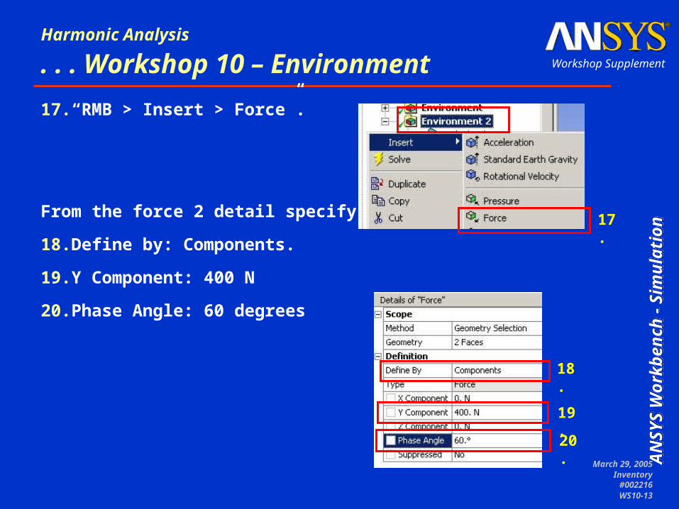
17.“RMB > Insert > Force”.
From the force 2 detail specify:
18.Define by: Components.
19.Y Component: 400 N
20.Phase Angle: 60 degrees
18.
19.
20.
17.

March 29, 2005Inventory
#002216WS10-14
AN
SY
S W
ork
ben
ch
- Sim
ula
tion
AN
SY
S W
ork
ben
ch
- Sim
ula
tion
AN
SY
S W
ork
ben
ch
- Sim
ula
tion
AN
SY
S W
ork
ben
ch
- Sim
ula
tion
Workshop Supplement
Harmonic Analysis
. . . Workshop 10 – Solution
21. Highlight the “Frequency Finder” in the solution branch in Environment 2 and RMB > Delete.
22. “RMB > Insert > Harmonics > Harmonic Tool”.
22.
21.

March 29, 2005Inventory
#002216WS10-15
AN
SY
S W
ork
ben
ch
- Sim
ula
tion
AN
SY
S W
ork
ben
ch
- Sim
ula
tion
AN
SY
S W
ork
ben
ch
- Sim
ula
tion
AN
SY
S W
ork
ben
ch
- Sim
ula
tion
Workshop Supplement
Harmonic Analysis
. . . Workshop 10 – Solution
23. Highlight the Harmonic Tool.
From the Harmonic Tool detail specify:
24. Range Maximum: 300 Hz.
25. Solution Intervals: 40.
26. Constant Damping Ratio: 0.02.24.
25.
26.
23.

March 29, 2005Inventory
#002216WS10-16
AN
SY
S W
ork
ben
ch
- Sim
ula
tion
AN
SY
S W
ork
ben
ch
- Sim
ula
tion
AN
SY
S W
ork
ben
ch
- Sim
ula
tion
AN
SY
S W
ork
ben
ch
- Sim
ula
tion
Workshop Supplement
Harmonic Analysis
. . . Workshop 10 – Solution
27. Switch the selection filter to “Edge” select.
28. Select the top edge (1) of the mounting hole shown below.
27.
28.

March 29, 2005Inventory
#002216WS10-17
AN
SY
S W
ork
ben
ch
- Sim
ula
tion
AN
SY
S W
ork
ben
ch
- Sim
ula
tion
AN
SY
S W
ork
ben
ch
- Sim
ula
tion
AN
SY
S W
ork
ben
ch
- Sim
ula
tion
Workshop Supplement
Harmonic Analysis
. . . Workshop 10 – Solution
29. “RMB > Insert > Frequency Response > Deformation”.
31. From the detail change the orientation to “Y Axis”.
29.
30.

March 29, 2005Inventory
#002216WS10-18
AN
SY
S W
ork
ben
ch
- Sim
ula
tion
AN
SY
S W
ork
ben
ch
- Sim
ula
tion
AN
SY
S W
ork
ben
ch
- Sim
ula
tion
AN
SY
S W
ork
ben
ch
- Sim
ula
tion
Workshop Supplement
Harmonic Analysis
. . . Workshop 10 – Solution
• Select the same edge as in step 29.
31. “RMB > Insert > Phase Response > Deformation”.
32. From the detail change the orientation to “Y Axis”.
33. Enter 200 in the Frequency field.
32.
33.
31.

March 29, 2005Inventory
#002216WS10-19
AN
SY
S W
ork
ben
ch
- Sim
ula
tion
AN
SY
S W
ork
ben
ch
- Sim
ula
tion
AN
SY
S W
ork
ben
ch
- Sim
ula
tion
AN
SY
S W
ork
ben
ch
- Sim
ula
tion
Workshop Supplement
Harmonic Analysis
. . . Workshop 10 – Solution
34. Select the top edge (1) of the mounting hole shown below.
• Repeat steps 30 through 34 to include results for this location.
34.

March 29, 2005Inventory
#002216WS10-20
AN
SY
S W
ork
ben
ch
- Sim
ula
tion
AN
SY
S W
ork
ben
ch
- Sim
ula
tion
AN
SY
S W
ork
ben
ch
- Sim
ula
tion
AN
SY
S W
ork
ben
ch
- Sim
ula
tion
Workshop Supplement
Harmonic Analysis
. . . Workshop 10 – Solution
35. Highlight the Harmonic Tool.
36. “RMB > Insert > Stress > Normal”.
• In the detail change the definition to:
37. Orientation: Y Axis
38. Frequency: 200 Hz 37.
38.
35.36.

March 29, 2005Inventory
#002216WS10-21
AN
SY
S W
ork
ben
ch
- Sim
ula
tion
AN
SY
S W
ork
ben
ch
- Sim
ula
tion
AN
SY
S W
ork
ben
ch
- Sim
ula
tion
AN
SY
S W
ork
ben
ch
- Sim
ula
tion
Workshop Supplement
Harmonic Analysis
. . . Workshop 10 – Solution
39. “RMB > Insert > Deformation > Directional”.
• In the detail change the definition to:
40. Orientation: Y Axis
41. Frequency: 200 Hz
• Solve
40.
41.
39.

March 29, 2005Inventory
#002216WS10-22
AN
SY
S W
ork
ben
ch
- Sim
ula
tion
AN
SY
S W
ork
ben
ch
- Sim
ula
tion
AN
SY
S W
ork
ben
ch
- Sim
ula
tion
AN
SY
S W
ork
ben
ch
- Sim
ula
tion
Workshop Supplement
Harmonic Analysis
. . . Workshop 10 – Results
• Highlight the Frequency response object. The default format is a Bode plot (see right) showing amplitude and phase angle in the same window.
• By changing the detail for the result other information can be viewed.

March 29, 2005Inventory
#002216WS10-23
AN
SY
S W
ork
ben
ch
- Sim
ula
tion
AN
SY
S W
ork
ben
ch
- Sim
ula
tion
AN
SY
S W
ork
ben
ch
- Sim
ula
tion
AN
SY
S W
ork
ben
ch
- Sim
ula
tion
Workshop Supplement
Harmonic Analysis
. . . Workshop 10 – Results
• The amplitude vs frequency plots can be used to inspect the deformation at the selected points.
• Recall our frequency of interest is 200 Hz.
200 Hz
Left Mount
Right Mount

March 29, 2005Inventory
#002216WS10-24
AN
SY
S W
ork
ben
ch
- Sim
ula
tion
AN
SY
S W
ork
ben
ch
- Sim
ula
tion
AN
SY
S W
ork
ben
ch
- Sim
ula
tion
AN
SY
S W
ork
ben
ch
- Sim
ula
tion
Workshop Supplement
Harmonic Analysis
. . . Workshop 10 – Results
• The phase response allows a comparison of the output (at the selected location) to the input forces. Recall (as this plot shows) we included a phase angle of 60 degrees when defining the second force load.

March 29, 2005Inventory
#002216WS10-25
AN
SY
S W
ork
ben
ch
- Sim
ula
tion
AN
SY
S W
ork
ben
ch
- Sim
ula
tion
AN
SY
S W
ork
ben
ch
- Sim
ula
tion
AN
SY
S W
ork
ben
ch
- Sim
ula
tion
Workshop Supplement
Harmonic Analysis
. . . Workshop 10 – Results
• Plotting contour results gives a picture of the overall structure with respect to a specific orientation, frequency and phase angle.

March 29, 2005Inventory
#002216WS10-26
AN
SY
S W
ork
ben
ch
- Sim
ula
tion
AN
SY
S W
ork
ben
ch
- Sim
ula
tion
AN
SY
S W
ork
ben
ch
- Sim
ula
tion
AN
SY
S W
ork
ben
ch
- Sim
ula
tion
Workshop Supplement
Harmonic Analysis
. . . Workshop 10 – Results
• Highlighting the Harmonic Tool and changing to the worksheet view brings up a summary of all harmonic results.