Harmonic Analysis Example
39
Harmonic Analysis Example The purpose of the following example system is to demonstrate the procedure required to perform a harmonic analysis for a system subjected to harmonic loads. Harmonic loads are periodic loads generated by reciprocating equipment or by flow generated vortices near closed tee branches or partially open valves. The periodic loads could have any shape. They have to be decomposed into a set of harmonics for analysis purposes. For example when a reciprocating compressor is operating it generates non-sinusoidal periodic pressure pulses for every revolution of the crank. These pulses generate unbalanced forces on the piping system. The unbalanced forces are more significant at locations where there is a change in pipe direction and the pressure at one end is out of phase with the pressure at the other end. The periodic forces can be decomposed into a set of harmonics or frequencies, each with different amplitude and phase. These harmonic loads can then be entered into AutoPIPE to perform harmonic load analysis. Choose from the following list of topics: Problem Definition Definition of the Harmonic Analysis Example in AutoPIPE AutoPIPE Harmonic Analysis Report
-
Upload
wendi-junaedi -
Category
Documents
-
view
277 -
download
2
description
harmonic analysis example
Transcript of Harmonic Analysis Example
Harmonic Analysis Example
The purpose of the following example system is to demonstrate the procedure required to perform a harmonic analysis for a system subjected to harmonic loads.
Harmonic loads are periodic loads generated by reciprocating equipment or by flow generated vortices near closed tee branches or partially open valves. The periodic loads could have any shape. They have to be decomposed into a set of harmonics for analysis purposes. For example when a reciprocating compressor is operating it generates non-sinusoidal periodic pressure pulses for every revolution of the crank. These pulses generate unbalanced forces on the piping system. The unbalanced forces are more significant at locations where there is a change in pipe direction and the pressure at one end is out of phase with the pressure at the other end. The periodic forces can be decomposed into a set of harmonics or frequencies, each with different amplitude and phase. These harmonic loads can then be entered into AutoPIPE to perform harmonic load analysis.
Choose from the following list of topics:
Problem Definition
Definition of the Harmonic Analysis Example in AutoPIPE
AutoPIPE Harmonic Analysis Report
Problem Definition: Harmonic Analysis
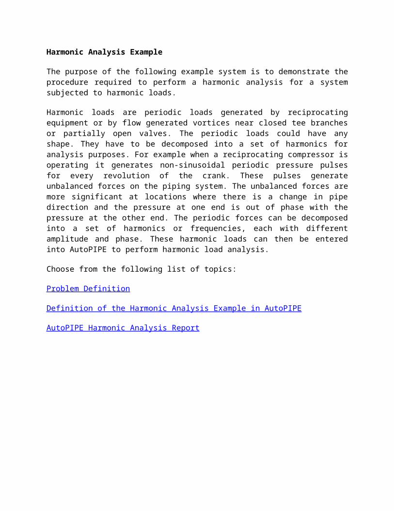
The suction side of a natural gas supply system with a reciprocating compressor is shown below. Two 6" suction lines are connected to the reciprocating compressor assembly. The reciprocating compressor assembly consists of 22" suction and discharge bottles, 8 " suction and discharge nozzles and 16" compressor cylinder assembly. The pressure at the suction bottle is 400 psi which is increased to 650 psi at the discharge bottle. Acoustic shaking forces which are periodic in nature are produced by the operation of the compressor. If the frequency, phase and magnitude of these shaking forces are known , the harmonic analysis utility of AutoPIPE can be used to perform the harmonic analysis. Up to 10 harmonic load cases H1, H2, H3 ... H10 can be created.
The acoustic shaking forces can be calculated using any acoustic simulation program or can be obtained from some industry guidelines (e.g. compressor’s manufacturers guidelines). The program PULS, another product of Bentley, can generate these forces in the form that can be used directly in AutoPIPE.
For this example, the acoustic shaking forces are computed using PULS. There were two critical speeds, 276 rpm and 280 rpm of the compressor that generated high shaking forces. To simplify this example only the 2 most critical harmonics associated with each speed are used in the harmonic load analysis. Since the compressor operates at a single speed, two harmonic load cases are considered in the analysis, one for each critical speed. A further simplification is to consider only two shaking forces.
1. Shaking force applied at point A5 due to unbalanced pressure at the suction bottle (A5-A6).
2. Shaking force applied at point A81 due to unbalanced pressure in the 6" suction line between elbows A8 &A9. (A81 is the mid point of segment between A8 & A9).
Reciprocating Compressor Example
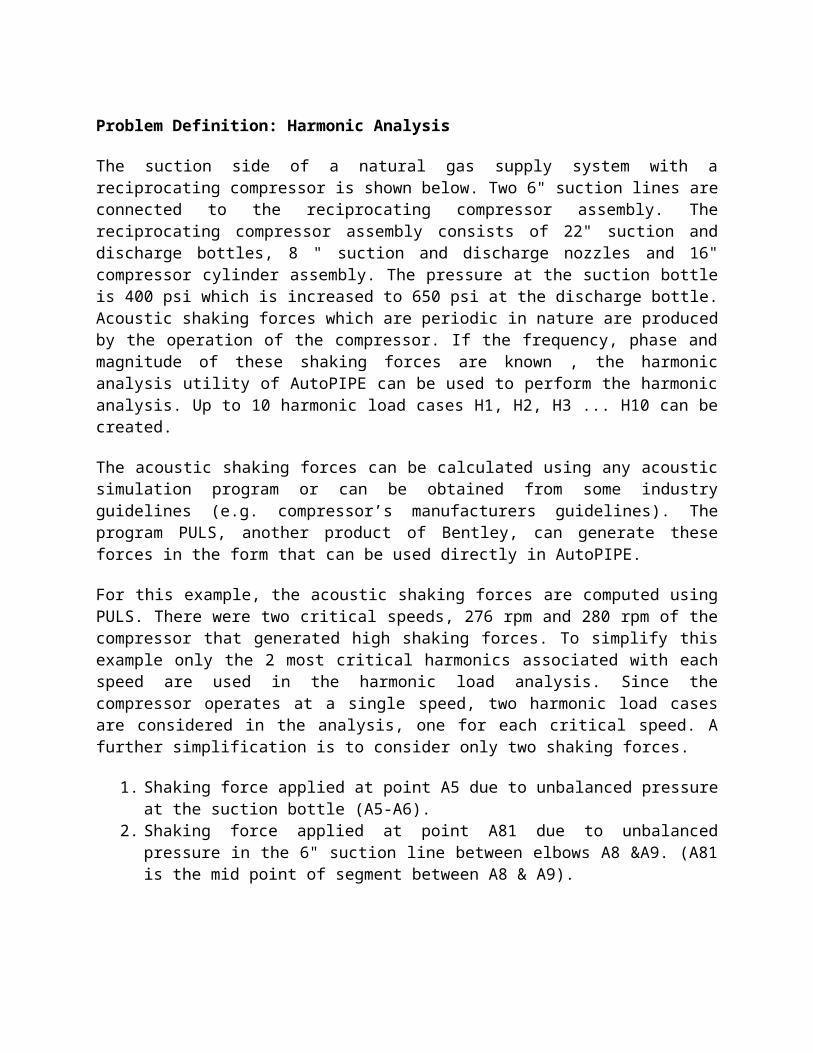
Note: For this example the flexibility of the nozzles has been ignored. The Figure below shows a suggested modeling approach for considering the flexibility of nozzles in the analysis. At the end of 8" nozzle pipe define a Nozzle element. AutoPIPE will automatically calculate the nozzle flexibility by taking into account the suction or discharge bottle dimensions. But these flexibility values are at the Bottle-Nozzle interface. To transfer the effect to the center of bottle a rigid pipe element can be attached between the nozzle and the center of the bottle.
Suggested Model of Nozzle/Bottle Interface

Definition of the Harmonic Analysis Example
This section illustrates the steps required to define and perform a Harmonic force analysis in AutoPIPE. Follow the text and enter data into the dialog fields exactly as shown and described in each of the following steps. The steps shown are configured for AutoPIPE for Windows.
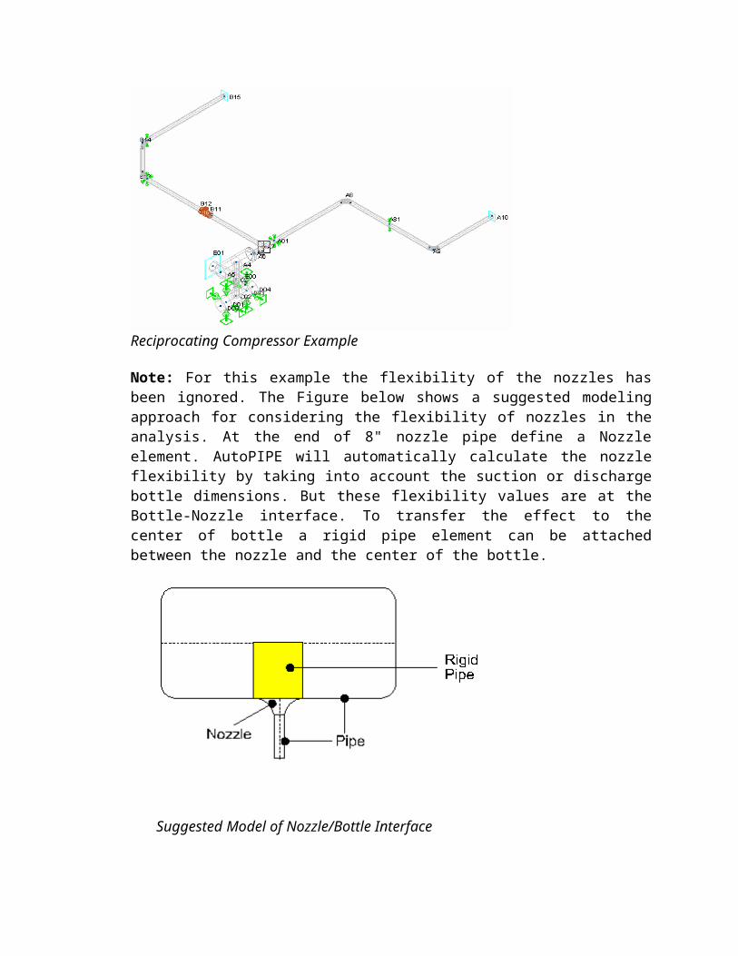
1. Open AutoPIPE then select File/Open and load the harmonic analysis file HRMEXP. A working model of a typical system with a reciprocating compressor is shown below.
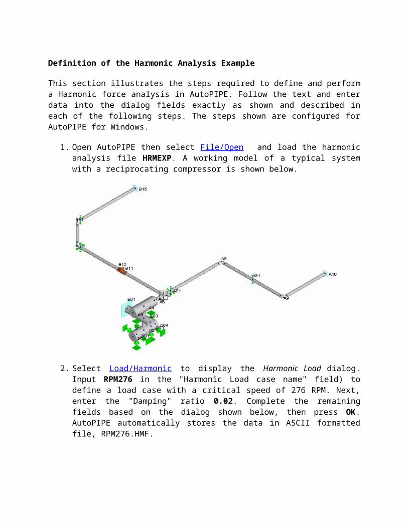
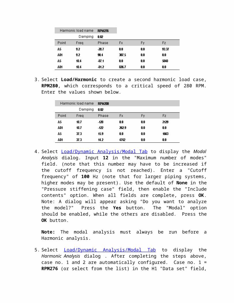
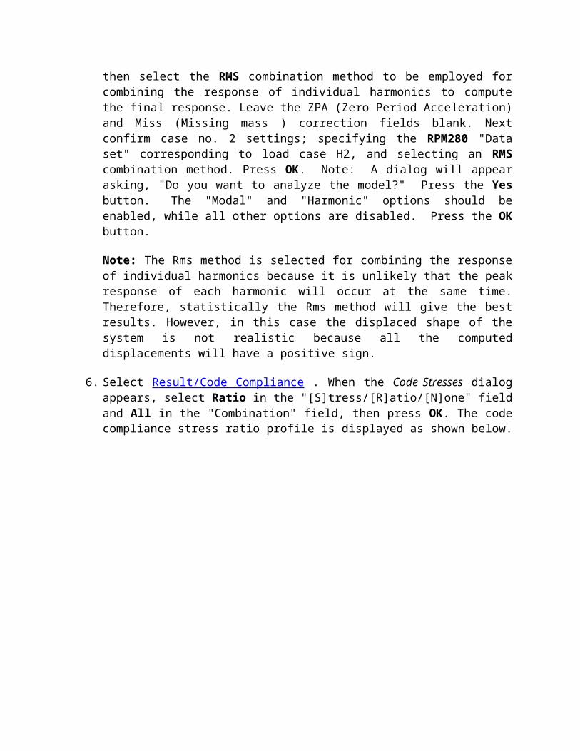
2. Select Load/Harmonic to display the Harmonic Load dialog. Input RPM276 in the "Harmonic Load case name" field) to define a load case with a critical speed of 276 RPM. Next, enter the "Damping" ratio 0.02. Complete the remaining fields based on the dialog shown below, then press OK. AutoPIPE automatically stores the data in ASCII formatted file, RPM276.HMF.
3. Select Load/Harmonic to create a second harmonic load case, RPM280, which corresponds to a critical speed of 280 RPM. Enter the values shown below.
4. Select Load/Dynamic Analysis/Modal Tab to display the Modal Analysis dialog. Input 12 in the "Maximum number of modes" field. (note that this number may have to be increased if the cutoff frequency is not reached). Enter a "Cutoff frequency" of 100 Hz (note that for larger piping systems, higher modes may be present). Use the default of None in the "Pressure stiffening case" field, then enable the "Include contents" option. When all fields are complete, press OK. Note: A dialog will appear asking "Do you want to analyze the model?" Press the Yes button. The "Modal" option should be enabled, while the others are disabled. Press the OK button.
Note: The modal analysis must always be run before a Harmonic analysis.
5. Select Load/Dynamic Analysis/Modal Tab to display the Harmonic Analysis dialog . After completing the steps above, case no. 1 and 2 are automatically configured. Case no. 1 = RPM276 (or select from the list) in the H1 "Data set" field, then select the RMS combination method to be employed for combining the response of individual harmonics to compute the final response. Leave the ZPA (Zero Period Acceleration) and Miss (Missing mass ) correction fields blank. Next confirm case no. 2 settings; specifying the RPM280 "Data set" corresponding to load case H2, and selecting an RMS combination method. Press OK. Note: A dialog will appear asking, "Do you want to analyze the model?" Press the Yes button. The "Modal" and "Harmonic" options should be enabled, while all other options are disabled. Press the OK button.
Note: The Rms method is selected for combining the response of individual harmonics because it is unlikely that the peak response of each harmonic will occur at the same time. Therefore, statistically the Rms method will give the best results. However, in this case the displaced shape of the system is not realistic because all the computed displacements will have a positive sign.
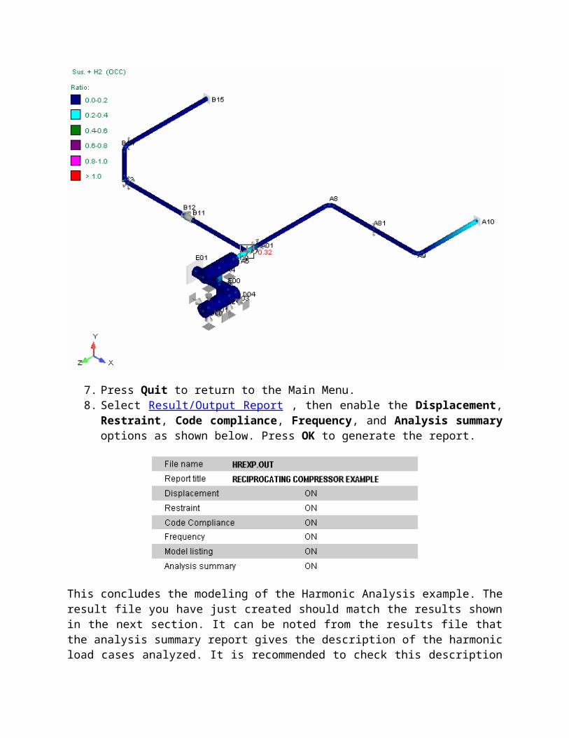
6. Select Result/Code Compliance . When the Code Stresses dialog appears, select Ratio in the "[S]tress/[R]atio/[N]one" field and All in the "Combination" field, then press OK. The code compliance stress ratio profile is displayed as shown below.
7. Press Quit to return to the Main Menu.8. Select Result/Output Report , then enable the Displacement, Restraint, Code compliance,
Frequency, and Analysis summary options as shown below. Press OK to generate the report.
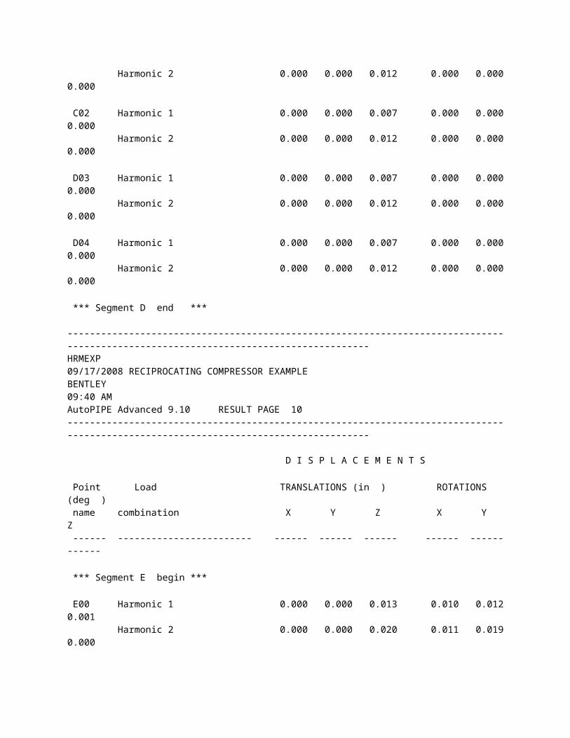
This concludes the modeling of the Harmonic Analysis example. The result file you have just created should match the results shown in the next section. It can be noted from the results file that the analysis summary report gives the description of the harmonic load cases analyzed. It is recommended to check this description to make sure that the data has been read by AutoPIPE correctly. The displacement report indicates that the maximum displacement and rotation occurs in the suction line at elbows A8 and A9. From the code compliance report it can be noted that the maximum stressed point is A7.
Press here to view the AutoPIPE Harmonic Analysis Report.
------------------------------------------------------------------------------------------------------------------------------------HRMEXP 09/17/2008 RECIPROCATING COMPRESSOR EXAMPLE BENTLEY 09:40 AM AutoPIPE Advanced 9.10 MODEL PAGE 1------------------------------------------------------------------------------------------------------------------------------------
* ******* ** ******* ******* *** ** ** ** ** ** ** ** ** ** ****** ** ** ** ** ** ** ** ** ** ** ** ***** ******* ** ******* ***** ********* ** ** ** ** ** ** ** ** ** ** ** ** ** ** ** ** ** ** ** ** ** ** ***** ** ***** ** ** ** ******* Pipe Stress Analysis and Design Program Version: 09.01.00.25 Edition: Advanced Developed and Maintained by BENTLEY SYSTEMS, INCORPORATED 1600 Riviera Ave., Suite 300 Walnut Creek, CA 94596
------------------------------------------------------------------------------------------------------------------------------------HRMEXP 09/17/2008 RECIPROCATING COMPRESSOR EXAMPLE BENTLEY 09:40 AM AutoPIPE Advanced 9.10 MODEL PAGE 2------------------------------------------------------------------------------------------------------------------------------------
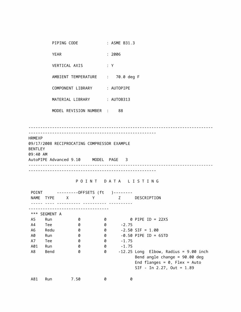
************************************************************ ** ** ** AUTOPIPE SYSTEM INFORMATION ** ** ** ************************************************************ SYSTEM NAME : HRMEXP PROJECT ID : RECIPROCATING COMPRESSOR EXAMPLE PREPARED BY : ______________________________ NZ CHECKED BY : ______________________________ KR 1ST APPROVER : ______________________________ 2ND APPROVER : ______________________________ PIPING CODE : ASME B31.3 YEAR : 2006 VERTICAL AXIS : Y AMBIENT TEMPERATURE : 70.0 deg F COMPONENT LIBRARY : AUTOPIPE MATERIAL LIBRARY : AUTOB313 MODEL REVISION NUMBER : 88
------------------------------------------------------------------------------------------------------------------------------------HRMEXP 09/17/2008 RECIPROCATING COMPRESSOR EXAMPLE BENTLEY 09:40 AM AutoPIPE Advanced 9.10 MODEL PAGE 3------------------------------------------------------------------------------------------------------------------------------------
P O I N T D A T A L I S T I N G
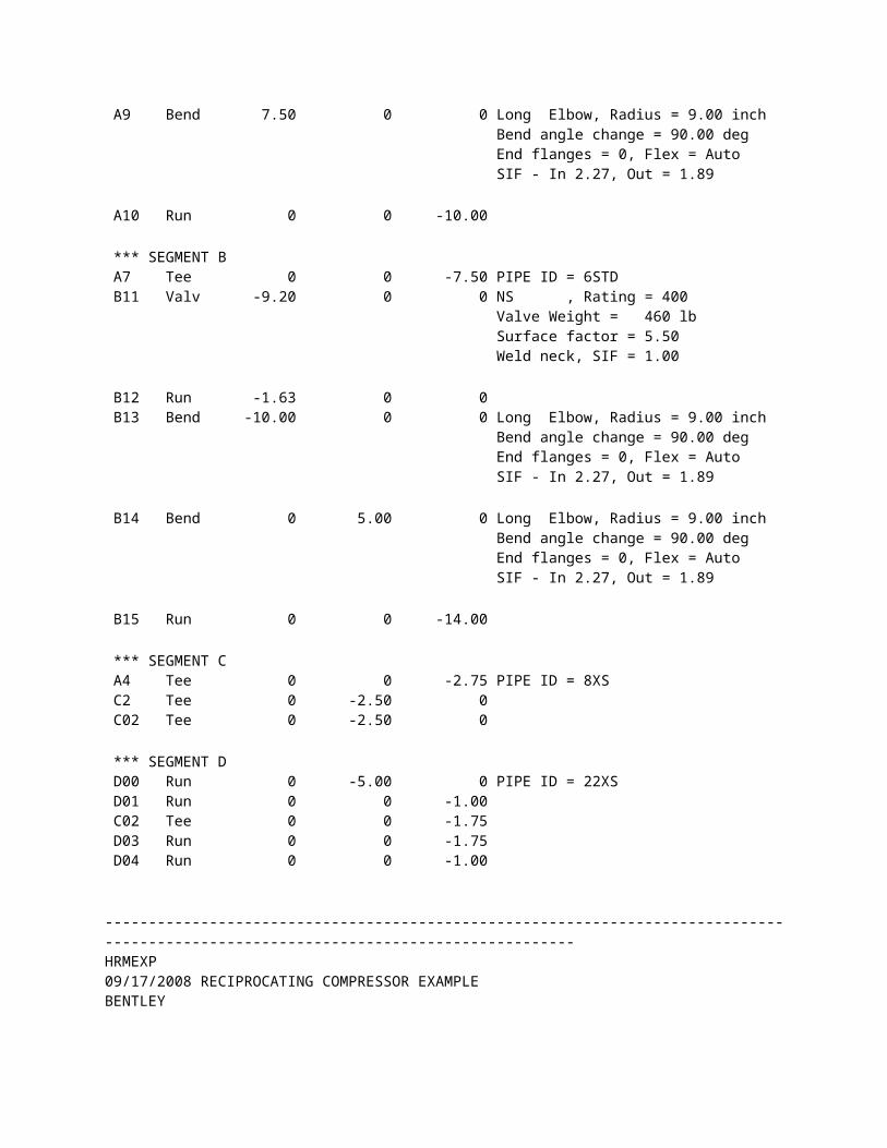
POINT ---------OFFSETS (ft )-------- NAME TYPE X Y Z DESCRIPTION ----- ---- ---------- ---------- ---------- ---------------------------------- *** SEGMENT A A5 Run 0 0 0 PIPE ID = 22XS A4 Tee 0 0 -2.75 A6 Redu 0 0 -2.50 SIF = 1.00 A0 Run 0 0 -0.50 PIPE ID = 6STD A7 Tee 0 0 -1.75 A01 Run 0 0 -1.75 A8 Bend 0 0 -12.25 Long Elbow, Radius = 9.00 inch Bend angle change = 90.00 deg End flanges = 0, Flex = Auto SIF - In 2.27, Out = 1.89 A81 Run 7.50 0 0 A9 Bend 7.50 0 0 Long Elbow, Radius = 9.00 inch Bend angle change = 90.00 deg End flanges = 0, Flex = Auto SIF - In 2.27, Out = 1.89 A10 Run 0 0 -10.00 *** SEGMENT B A7 Tee 0 0 -7.50 PIPE ID = 6STD B11 Valv -9.20 0 0 NS , Rating = 400 Valve Weight = 460 lb Surface factor = 5.50 Weld neck, SIF = 1.00 B12 Run -1.63 0 0 B13 Bend -10.00 0 0 Long Elbow, Radius = 9.00 inch Bend angle change = 90.00 deg End flanges = 0, Flex = Auto SIF - In 2.27, Out = 1.89 B14 Bend 0 5.00 0 Long Elbow, Radius = 9.00 inch Bend angle change = 90.00 deg End flanges = 0, Flex = Auto SIF - In 2.27, Out = 1.89 B15 Run 0 0 -14.00 *** SEGMENT C A4 Tee 0 0 -2.75 PIPE ID = 8XS C2 Tee 0 -2.50 0 C02 Tee 0 -2.50 0 *** SEGMENT D D00 Run 0 -5.00 0 PIPE ID = 22XS D01 Run 0 0 -1.00 C02 Tee 0 0 -1.75 D03 Run 0 0 -1.75 D04 Run 0 0 -1.00
------------------------------------------------------------------------------------------------------------------------------------HRMEXP 09/17/2008 RECIPROCATING COMPRESSOR EXAMPLE BENTLEY 09:40 AM AutoPIPE Advanced 9.10 MODEL PAGE 4------------------------------------------------------------------------------------------------------------------------------------
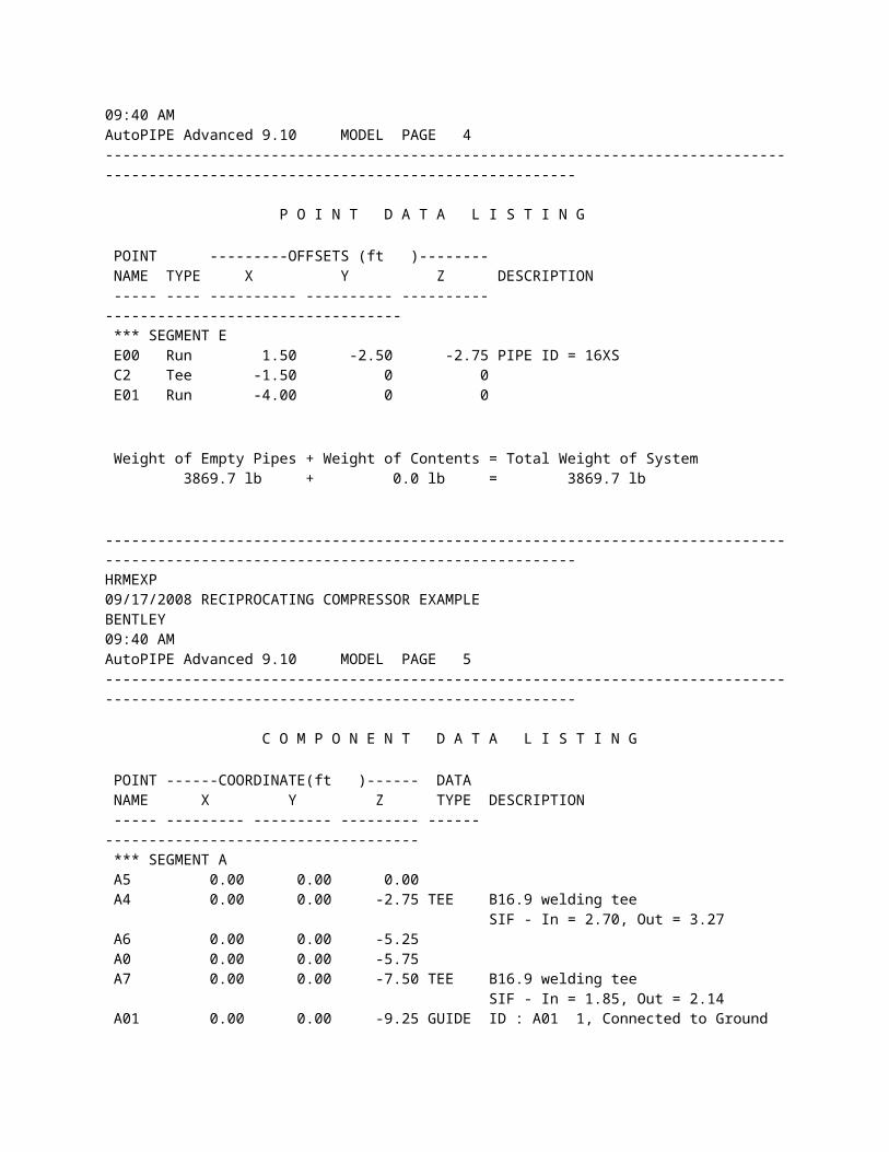
P O I N T D A T A L I S T I N G POINT ---------OFFSETS (ft )-------- NAME TYPE X Y Z DESCRIPTION ----- ---- ---------- ---------- ---------- ---------------------------------- *** SEGMENT E E00 Run 1.50 -2.50 -2.75 PIPE ID = 16XS C2 Tee -1.50 0 0 E01 Run -4.00 0 0 Weight of Empty Pipes + Weight of Contents = Total Weight of System 3869.7 lb + 0.0 lb = 3869.7 lb
------------------------------------------------------------------------------------------------------------------------------------HRMEXP 09/17/2008 RECIPROCATING COMPRESSOR EXAMPLE BENTLEY 09:40 AM AutoPIPE Advanced 9.10 MODEL PAGE 5------------------------------------------------------------------------------------------------------------------------------------
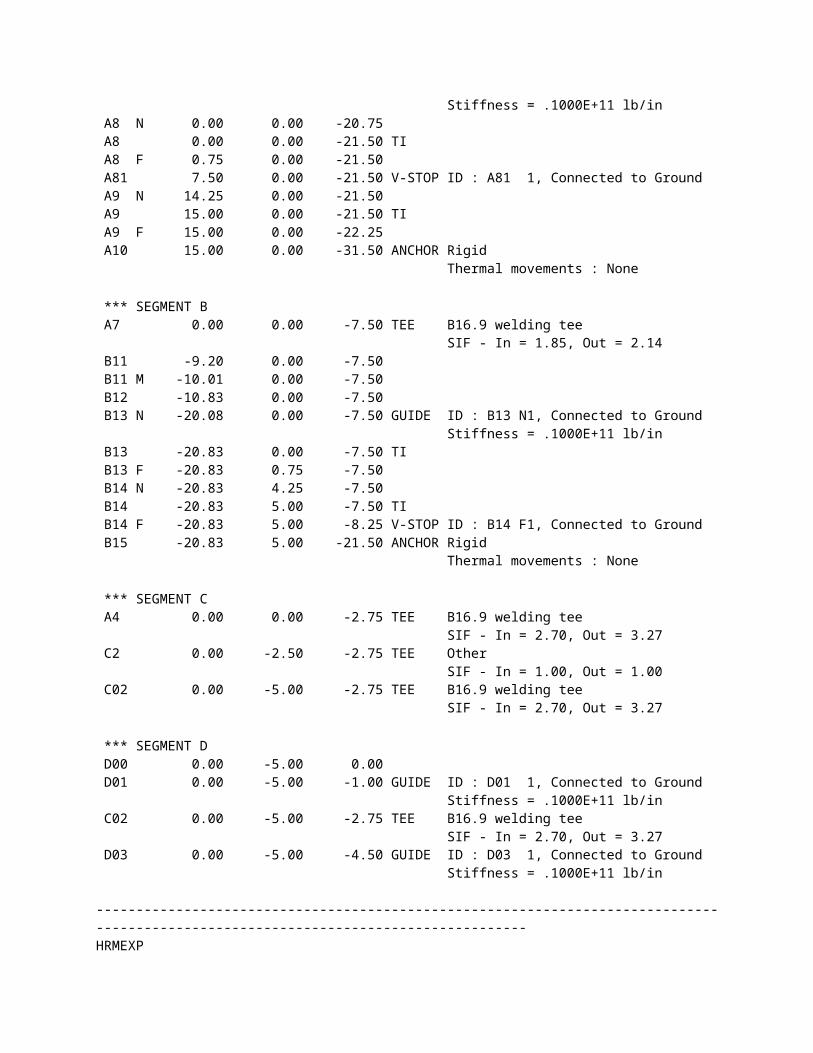
C O M P O N E N T D A T A L I S T I N G POINT ------COORDINATE(ft )------ DATA NAME X Y Z TYPE DESCRIPTION ----- --------- --------- --------- ------ ------------------------------------ *** SEGMENT A A5 0.00 0.00 0.00 A4 0.00 0.00 -2.75 TEE B16.9 welding tee SIF - In = 2.70, Out = 3.27 A6 0.00 0.00 -5.25 A0 0.00 0.00 -5.75 A7 0.00 0.00 -7.50 TEE B16.9 welding tee SIF - In = 1.85, Out = 2.14 A01 0.00 0.00 -9.25 GUIDE ID : A01 1, Connected to Ground Stiffness = .1000E+11 lb/in A8 N 0.00 0.00 -20.75 A8 0.00 0.00 -21.50 TI
A8 F 0.75 0.00 -21.50 A81 7.50 0.00 -21.50 V-STOP ID : A81 1, Connected to Ground A9 N 14.25 0.00 -21.50 A9 15.00 0.00 -21.50 TI A9 F 15.00 0.00 -22.25 A10 15.00 0.00 -31.50 ANCHOR Rigid Thermal movements : None *** SEGMENT B A7 0.00 0.00 -7.50 TEE B16.9 welding tee SIF - In = 1.85, Out = 2.14 B11 -9.20 0.00 -7.50 B11 M -10.01 0.00 -7.50 B12 -10.83 0.00 -7.50 B13 N -20.08 0.00 -7.50 GUIDE ID : B13 N1, Connected to Ground Stiffness = .1000E+11 lb/in B13 -20.83 0.00 -7.50 TI B13 F -20.83 0.75 -7.50 B14 N -20.83 4.25 -7.50 B14 -20.83 5.00 -7.50 TI B14 F -20.83 5.00 -8.25 V-STOP ID : B14 F1, Connected to Ground B15 -20.83 5.00 -21.50 ANCHOR Rigid Thermal movements : None *** SEGMENT C A4 0.00 0.00 -2.75 TEE B16.9 welding tee SIF - In = 2.70, Out = 3.27 C2 0.00 -2.50 -2.75 TEE Other SIF - In = 1.00, Out = 1.00 C02 0.00 -5.00 -2.75 TEE B16.9 welding tee SIF - In = 2.70, Out = 3.27 *** SEGMENT D D00 0.00 -5.00 0.00 D01 0.00 -5.00 -1.00 GUIDE ID : D01 1, Connected to Ground Stiffness = .1000E+11 lb/in C02 0.00 -5.00 -2.75 TEE B16.9 welding tee SIF - In = 2.70, Out = 3.27 D03 0.00 -5.00 -4.50 GUIDE ID : D03 1, Connected to Ground Stiffness = .1000E+11 lb/in
------------------------------------------------------------------------------------------------------------------------------------HRMEXP 09/17/2008 RECIPROCATING COMPRESSOR EXAMPLE BENTLEY 09:40 AM AutoPIPE Advanced 9.10 MODEL PAGE 6------------------------------------------------------------------------------------------------------------------------------------
C O M P O N E N T D A T A L I S T I N G POINT ------COORDINATE(ft )------ DATA NAME X Y Z TYPE DESCRIPTION
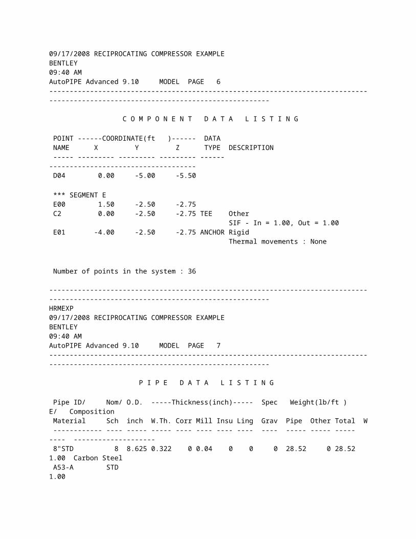
----- --------- --------- --------- ------ ------------------------------------ D04 0.00 -5.00 -5.50 *** SEGMENT E E00 1.50 -2.50 -2.75 C2 0.00 -2.50 -2.75 TEE Other SIF - In = 1.00, Out = 1.00 E01 -4.00 -2.50 -2.75 ANCHOR Rigid Thermal movements : None Number of points in the system : 36
------------------------------------------------------------------------------------------------------------------------------------HRMEXP 09/17/2008 RECIPROCATING COMPRESSOR EXAMPLE BENTLEY 09:40 AM AutoPIPE Advanced 9.10 MODEL PAGE 7------------------------------------------------------------------------------------------------------------------------------------
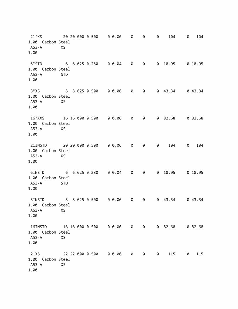
P I P E D A T A L I S T I N G Pipe ID/ Nom/ O.D. -----Thickness(inch)----- Spec Weight(lb/ft ) E/ Composition Material Sch inch W.Th. Corr Mill Insu Ling Grav Pipe Other Total W ------------ ---- ----- ----- ---- ---- ---- ---- ---- ----- ----- ----- ---- -------------------- 8"STD 8 8.625 0.322 0 0.04 0 0 0 28.52 0 28.52 1.00 Carbon Steel A53-A STD 1.00 21"XS 20 20.000 0.500 0 0.06 0 0 0 104 0 104 1.00 Carbon Steel A53-A XS 1.00 6"STD 6 6.625 0.280 0 0.04 0 0 0 18.95 0 18.95 1.00 Carbon Steel A53-A STD 1.00 8"XS 8 8.625 0.500 0 0.06 0 0 0 43.34 0 43.34 1.00 Carbon Steel A53-A XS 1.00 16"XXS 16 16.000 0.500 0 0.06 0 0 0 82.68 0 82.68 1.00 Carbon Steel A53-A XS 1.00
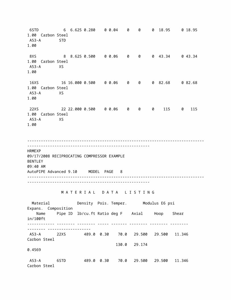
21INSTD 20 20.000 0.500 0 0.06 0 0 0 104 0 104 1.00 Carbon Steel A53-A XS 1.00 6INSTD 6 6.625 0.280 0 0.04 0 0 0 18.95 0 18.95 1.00 Carbon Steel A53-A STD 1.00 8INSTD 8 8.625 0.500 0 0.06 0 0 0 43.34 0 43.34 1.00 Carbon Steel A53-A XS 1.00 16INSTD 16 16.000 0.500 0 0.06 0 0 0 82.68 0 82.68 1.00 Carbon Steel A53-A XS 1.00 21XS 22 22.000 0.500 0 0.06 0 0 0 115 0 115 1.00 Carbon Steel A53-A XS 1.00 6STD 6 6.625 0.280 0 0.04 0 0 0 18.95 0 18.95 1.00 Carbon Steel A53-A STD 1.00 8XS 8 8.625 0.500 0 0.06 0 0 0 43.34 0 43.34 1.00 Carbon Steel A53-A XS 1.00 16XS 16 16.000 0.500 0 0.06 0 0 0 82.68 0 82.68 1.00 Carbon Steel A53-A XS 1.00 22XS 22 22.000 0.500 0 0.06 0 0 0 115 0 115 1.00 Carbon Steel A53-A XS 1.00
------------------------------------------------------------------------------------------------------------------------------------HRMEXP 09/17/2008 RECIPROCATING COMPRESSOR EXAMPLE BENTLEY 09:40 AM AutoPIPE Advanced 9.10 MODEL PAGE 8------------------------------------------------------------------------------------------------------------------------------------
M A T E R I A L D A T A L I S T I N G
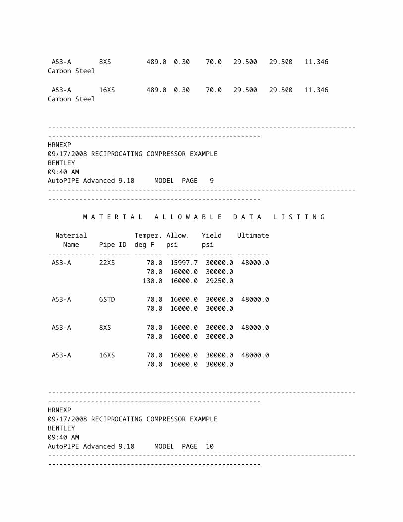
Material Density Pois. Temper. Modulus E6 psi Expans. Composition Name Pipe ID lb/cu.ft Ratio deg F Axial Hoop Shear in/100ft ------------ -------- -------- ----- ------- -------- -------- -------- -------- ------------------- A53-A 22XS 489.0 0.30 70.0 29.500 29.500 11.346 Carbon Steel 130.0 29.174 0.4569 A53-A 6STD 489.0 0.30 70.0 29.500 29.500 11.346 Carbon Steel A53-A 8XS 489.0 0.30 70.0 29.500 29.500 11.346 Carbon Steel A53-A 16XS 489.0 0.30 70.0 29.500 29.500 11.346 Carbon Steel
------------------------------------------------------------------------------------------------------------------------------------HRMEXP 09/17/2008 RECIPROCATING COMPRESSOR EXAMPLE BENTLEY 09:40 AM AutoPIPE Advanced 9.10 MODEL PAGE 9------------------------------------------------------------------------------------------------------------------------------------
M A T E R I A L A L L O W A B L E D A T A L I S T I N G Material Temper. Allow. Yield Ultimate Name Pipe ID deg F psi psi ------------ -------- ------- -------- -------- -------- A53-A 22XS 70.0 15997.7 30000.0 48000.0 70.0 16000.0 30000.0 130.0 16000.0 29250.0 A53-A 6STD 70.0 16000.0 30000.0 48000.0 70.0 16000.0 30000.0 A53-A 8XS 70.0 16000.0 30000.0 48000.0 70.0 16000.0 30000.0 A53-A 16XS 70.0 16000.0 30000.0 48000.0 70.0 16000.0 30000.0
------------------------------------------------------------------------------------------------------------------------------------HRMEXP 09/17/2008 RECIPROCATING COMPRESSOR EXAMPLE BENTLEY
09:40 AM AutoPIPE Advanced 9.10 MODEL PAGE 10------------------------------------------------------------------------------------------------------------------------------------
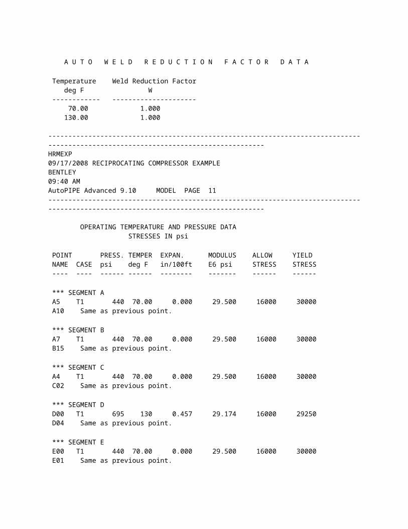
A U T O W E L D R E D U C T I O N F A C T O R D A T A Temperature Weld Reduction Factor deg F W ------------ --------------------- 70.00 1.000 130.00 1.000
------------------------------------------------------------------------------------------------------------------------------------HRMEXP 09/17/2008 RECIPROCATING COMPRESSOR EXAMPLE BENTLEY 09:40 AM AutoPIPE Advanced 9.10 MODEL PAGE 11------------------------------------------------------------------------------------------------------------------------------------
OPERATING TEMPERATURE AND PRESSURE DATA STRESSES IN psi POINT PRESS. TEMPER EXPAN. MODULUS ALLOW YIELD NAME CASE psi deg F in/100ft E6 psi STRESS STRESS ---- ---- ------ ------ -------- ------- ------ ------ *** SEGMENT A A5 T1 440 70.00 0.000 29.500 16000 30000 A10 Same as previous point. *** SEGMENT B A7 T1 440 70.00 0.000 29.500 16000 30000 B15 Same as previous point. *** SEGMENT C A4 T1 440 70.00 0.000 29.500 16000 30000 C02 Same as previous point. *** SEGMENT D D00 T1 695 130 0.457 29.174 16000 29250 D04 Same as previous point. *** SEGMENT E E00 T1 440 70.00 0.000 29.500 16000 30000 E01 Same as previous point. u User-defined value * Non-code material for allowable stress; Non-standard material for expansion and modulus
------------------------------------------------------------------------------------------------------------------------------------HRMEXP 09/17/2008 RECIPROCATING COMPRESSOR EXAMPLE BENTLEY 09:40 AM AutoPIPE Advanced 9.10 RESULT PAGE 1------------------------------------------------------------------------------------------------------------------------------------
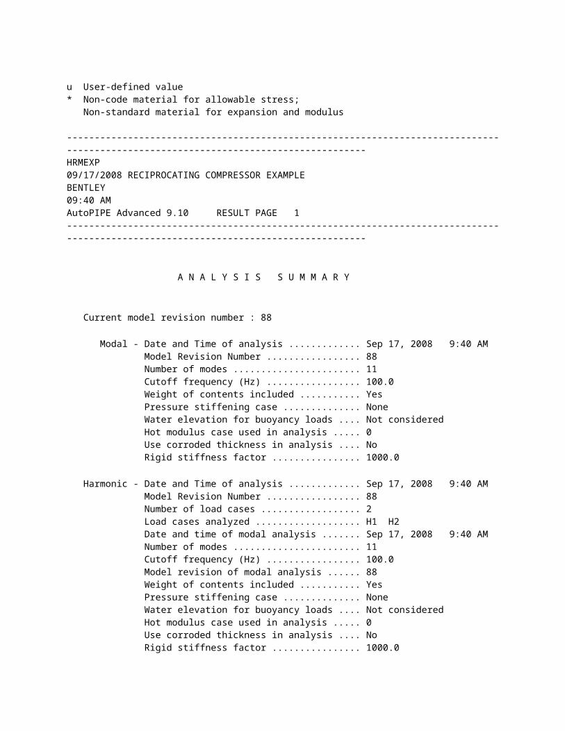
A N A L Y S I S S U M M A R Y Current model revision number : 88 Modal - Date and Time of analysis ............. Sep 17, 2008 9:40 AM Model Revision Number ................. 88 Number of modes ....................... 11 Cutoff frequency (Hz) ................. 100.0 Weight of contents included ........... Yes Pressure stiffening case .............. None Water elevation for buoyancy loads .... Not considered Hot modulus case used in analysis ..... 0 Use corroded thickness in analysis .... No Rigid stiffness factor ................ 1000.0 Harmonic - Date and Time of analysis ............. Sep 17, 2008 9:40 AM Model Revision Number ................. 88 Number of load cases .................. 2 Load cases analyzed ................... H1 H2 Date and time of modal analysis ....... Sep 17, 2008 9:40 AM Number of modes ....................... 11 Cutoff frequency (Hz) ................. 100.0 Model revision of modal analysis ...... 88 Weight of contents included ........... Yes Pressure stiffening case .............. None Water elevation for buoyancy loads .... Not considered Hot modulus case used in analysis ..... 0 Use corroded thickness in analysis .... No Rigid stiffness factor ................ 1000.0
------------------------------------------------------------------------------------------------------------------------------------HRMEXP 09/17/2008 RECIPROCATING COMPRESSOR EXAMPLE BENTLEY 09:40 AM AutoPIPE Advanced 9.10 RESULT PAGE 2------------------------------------------------------------------------------------------------------------------------------------
CODE COMPLIANCE COMBINATIONS <Description> Allowable
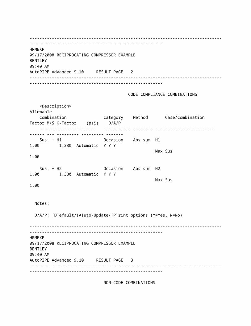
Combination Category Method Case/Combination Factor M/S K-Factor (psi) D/A/P ----------------------- ----------- -------- ------------------------ ------ --- --------- --------- ------- Sus. + H1 Occasion Abs sum H1 1.00 1.330 Automatic Y Y Y Max Sus 1.00 Sus. + H2 Occasion Abs sum H2 1.00 1.330 Automatic Y Y Y Max Sus 1.00 Notes: D/A/P: [D]efault/[A]uto-Update/[P]rint options (Y=Yes, N=No)
------------------------------------------------------------------------------------------------------------------------------------HRMEXP 09/17/2008 RECIPROCATING COMPRESSOR EXAMPLE BENTLEY 09:40 AM AutoPIPE Advanced 9.10 RESULT PAGE 3------------------------------------------------------------------------------------------------------------------------------------
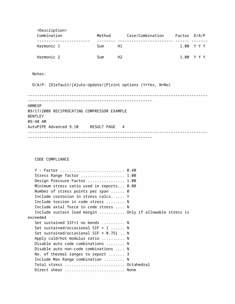
NON-CODE COMBINATIONS <Description> Combination Method Case/Combination Factor D/A/P ----------------------- -------- ------------------------ ------ ------- Harmonic 1 Sum H1 1.00 Y Y Y Harmonic 2 Sum H2 1.00 Y Y Y Notes: D/A/P: [D]efault/[A]uto-Update/[P]rint options (Y=Yes, N=No)
------------------------------------------------------------------------------------------------------------------------------------HRMEXP 09/17/2008 RECIPROCATING COMPRESSOR EXAMPLE BENTLEY 09:40 AM AutoPIPE Advanced 9.10 RESULT PAGE 4------------------------------------------------------------------------------------------------------------------------------------
CODE COMPLIANCE
Y - Factor ............................ 0.40 Stress Range factor ................... 1.00 Design Pressure Factor ................ 1.00 Minimum stress ratio used in reports... 0.00 Number of stress points per span ...... 0 Include corrosion in stress calcs. .... Y Include torsion in code stress ........ N Include axial force in code stress .... N Include sustain load margin ........... Only if allowable stress is exceeded Set sustained SIF=1 no bends .......... N Set sustained/occasional SIF = 1 ...... N Set sustained/occasional SIF = 0.75i .. N Apply cold/hot modulus ratio .......... N Disable auto code combinations ........ N Disable auto non-code combinations .... N No. of thermal ranges to report ....... 3 Include Max Range combination ......... N Total stress .......................... Octahedral Direct shear .......................... None Longitudinal pressure calculation ..... PD/4t Use code case 178 ..................... N Inc. Axial Str and Pcase in Sustained.. N Use alternate occasional allowable .... N Apply circumferential weld W factor ... N
------------------------------------------------------------------------------------------------------------------------------------HRMEXP 09/17/2008 RECIPROCATING COMPRESSOR EXAMPLE BENTLEY 09:40 AM AutoPIPE Advanced 9.10 RESULT PAGE 5------------------------------------------------------------------------------------------------------------------------------------
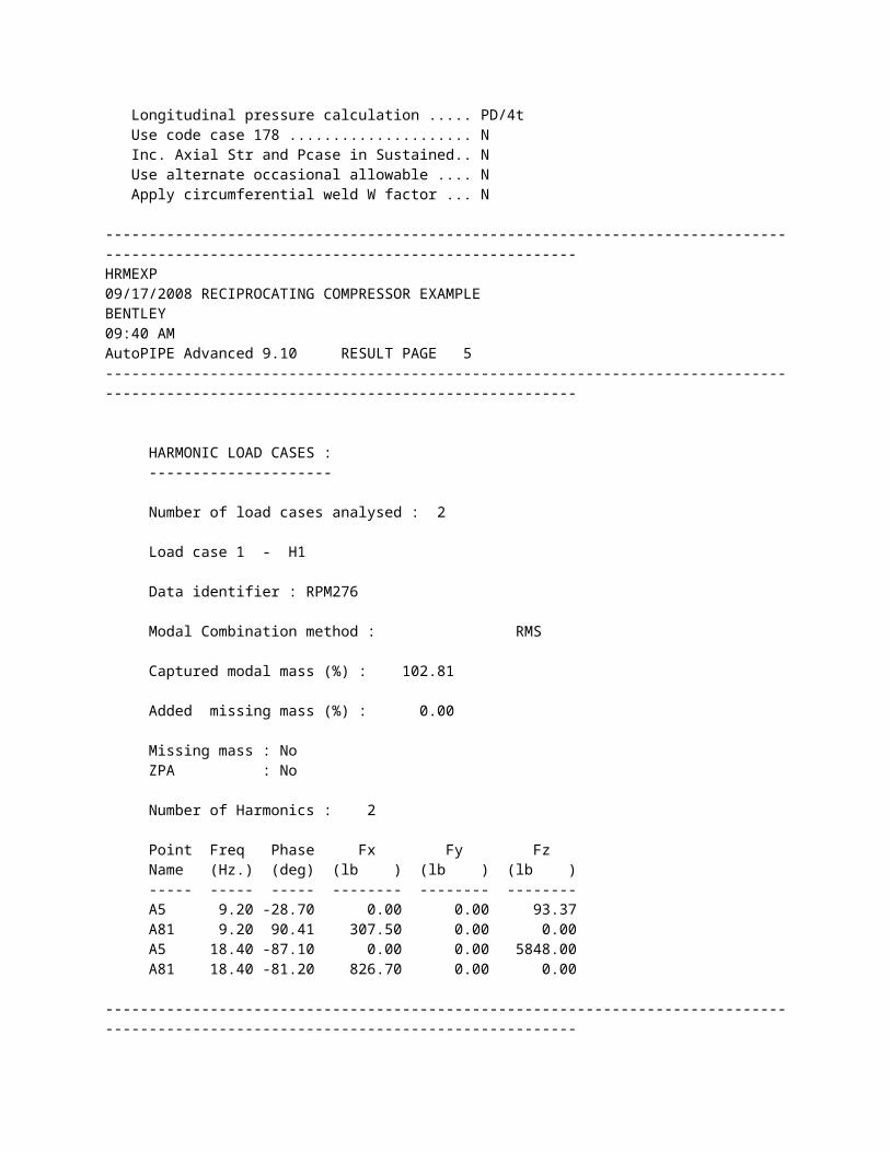
HARMONIC LOAD CASES : ---------------------
Number of load cases analysed : 2
Load case 1 - H1
Data identifier : RPM276
Modal Combination method : RMS
Captured modal mass (%) : 102.81
Added missing mass (%) : 0.00
Missing mass : No ZPA : No
Number of Harmonics : 2
Point Freq Phase Fx Fy Fz Name (Hz.) (deg) (lb ) (lb ) (lb ) ----- ----- ----- -------- -------- -------- A5 9.20 -28.70 0.00 0.00 93.37 A81 9.20 90.41 307.50 0.00 0.00 A5 18.40 -87.10 0.00 0.00 5848.00 A81 18.40 -81.20 826.70 0.00 0.00
------------------------------------------------------------------------------------------------------------------------------------HRMEXP 09/17/2008 RECIPROCATING COMPRESSOR EXAMPLE BENTLEY 09:40 AM AutoPIPE Advanced 9.10 RESULT PAGE 6------------------------------------------------------------------------------------------------------------------------------------
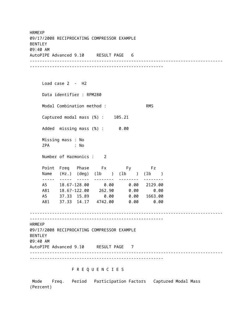
Load case 2 - H2
Data identifier : RPM280
Modal Combination method : RMS
Captured modal mass (%) : 105.21
Added missing mass (%) : 0.00
Missing mass : No ZPA : No
Number of Harmonics : 2
Point Freq Phase Fx Fy Fz Name (Hz.) (deg) (lb ) (lb ) (lb ) ----- ----- ----- -------- -------- -------- A5 18.67-128.00 0.00 0.00 2129.00 A81 18.67-122.00 262.90 0.00 0.00 A5 37.33 15.89 0.00 0.00 1663.00 A81 37.33 14.17 4742.00 0.00 0.00
------------------------------------------------------------------------------------------------------------------------------------HRMEXP 09/17/2008 RECIPROCATING COMPRESSOR EXAMPLE BENTLEY 09:40 AM AutoPIPE Advanced 9.10 RESULT PAGE 7------------------------------------------------------------------------------------------------------------------------------------
F R E Q U E N C I E S
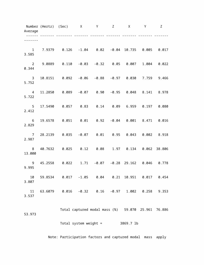
Mode Freq. Period Participation Factors Captured Modal Mass (Percent) Number (Hertz) (Sec) X Y Z X Y Z Average ------ ------- -------- ------- ------- ------- ------- ------- ------- ------- 1 7.9379 0.126 -1.04 0.02 -0.04 10.735 0.005 0.017 3.585 2 9.0889 0.110 -0.03 -0.32 0.05 0.007 1.004 0.022 0.344 3 10.8151 0.092 -0.06 -0.88 -0.97 0.030 7.759 9.466 5.752 4 11.2850 0.089 -0.07 0.90 -0.95 0.048 8.141 8.978 5.722 5 17.5490 0.057 0.83 0.14 0.09 6.959 0.197 0.080 2.412 6 19.6578 0.051 0.01 0.92 -0.04 0.001 8.471 0.016 2.829 7 28.2139 0.035 -0.07 0.01 0.95 0.043 0.002 8.918 2.987 8 40.7632 0.025 0.12 0.08 1.97 0.134 0.062 38.806 13.000 9 45.2558 0.022 1.71 -0.07 -0.28 29.162 0.046 0.778 9.995 10 59.8534 0.017 -1.05 0.04 0.21 10.951 0.017 0.454 3.807 11 63.6079 0.016 -0.32 0.16 -0.97 1.002 0.258 9.353 3.537
Total captured modal mass (%) 59.070 25.961 76.886 53.973
Total system weight = 3869.7 lb
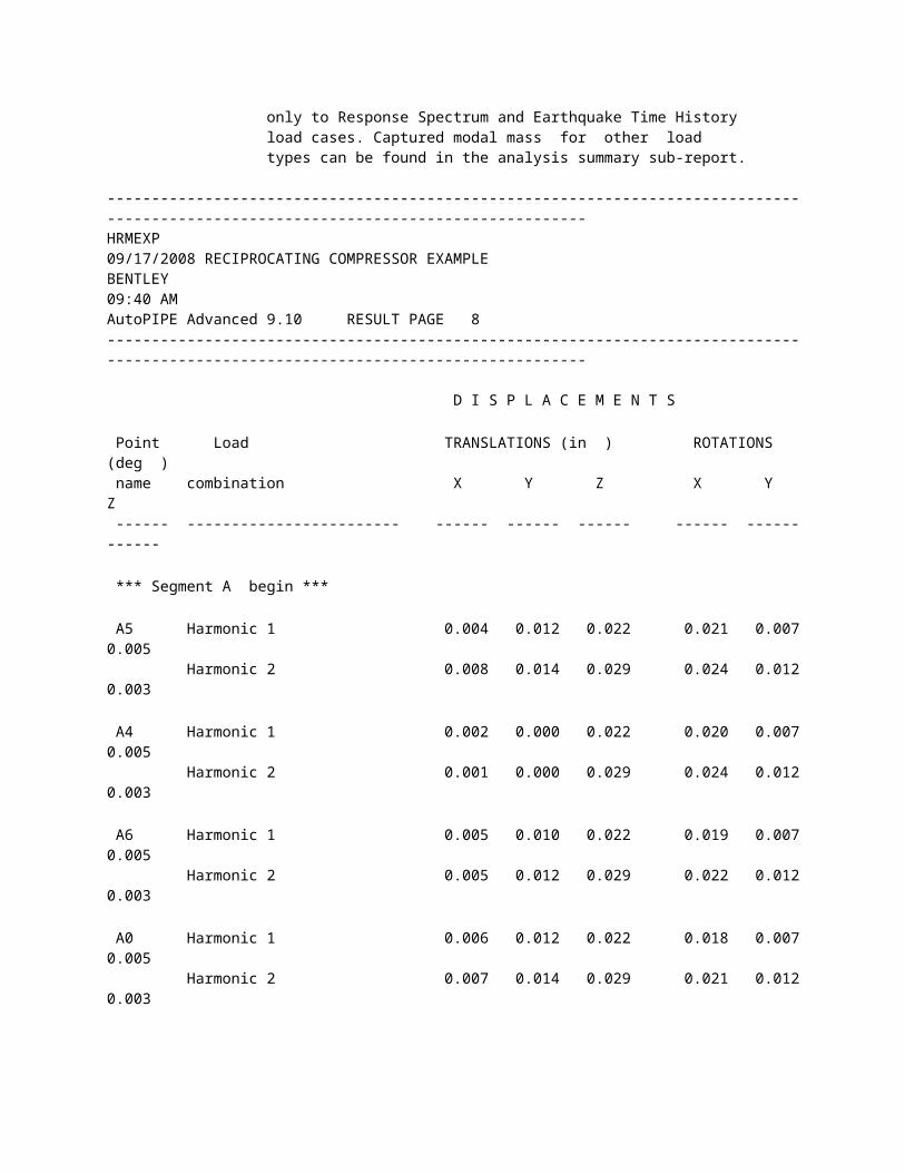
Note: Participation factors and captured modal mass apply only to Response Spectrum and Earthquake Time History load cases. Captured modal mass for other load types can be found in the analysis summary sub-report.
------------------------------------------------------------------------------------------------------------------------------------HRMEXP 09/17/2008 RECIPROCATING COMPRESSOR EXAMPLE BENTLEY
09:40 AM AutoPIPE Advanced 9.10 RESULT PAGE 8------------------------------------------------------------------------------------------------------------------------------------
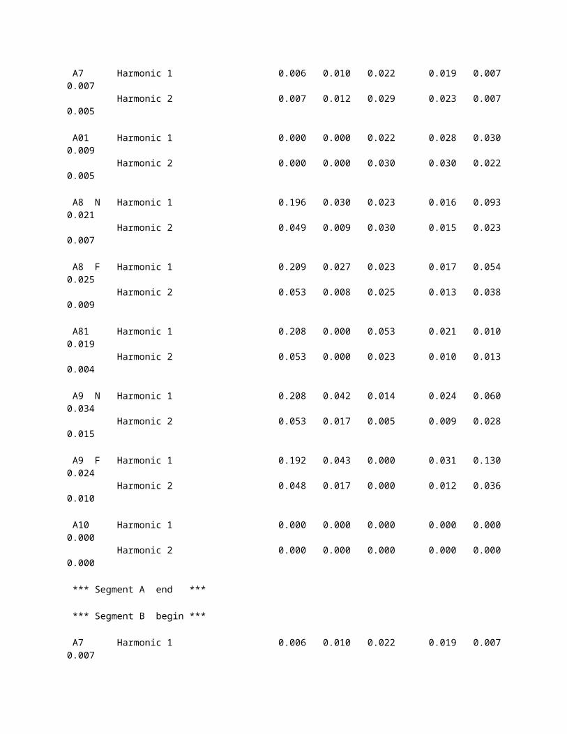
D I S P L A C E M E N T S Point Load TRANSLATIONS (in ) ROTATIONS (deg ) name combination X Y Z X Y Z ------ ------------------------ ------ ------ ------ ------ ------ ------ *** Segment A begin *** A5 Harmonic 1 0.004 0.012 0.022 0.021 0.007 0.005 Harmonic 2 0.008 0.014 0.029 0.024 0.012 0.003 A4 Harmonic 1 0.002 0.000 0.022 0.020 0.007 0.005 Harmonic 2 0.001 0.000 0.029 0.024 0.012 0.003 A6 Harmonic 1 0.005 0.010 0.022 0.019 0.007 0.005 Harmonic 2 0.005 0.012 0.029 0.022 0.012 0.003 A0 Harmonic 1 0.006 0.012 0.022 0.018 0.007 0.005 Harmonic 2 0.007 0.014 0.029 0.021 0.012 0.003 A7 Harmonic 1 0.006 0.010 0.022 0.019 0.007 0.007 Harmonic 2 0.007 0.012 0.029 0.023 0.007 0.005 A01 Harmonic 1 0.000 0.000 0.022 0.028 0.030 0.009 Harmonic 2 0.000 0.000 0.030 0.030 0.022 0.005 A8 N Harmonic 1 0.196 0.030 0.023 0.016 0.093 0.021 Harmonic 2 0.049 0.009 0.030 0.015 0.023 0.007 A8 F Harmonic 1 0.209 0.027 0.023 0.017 0.054 0.025 Harmonic 2 0.053 0.008 0.025 0.013 0.038 0.009
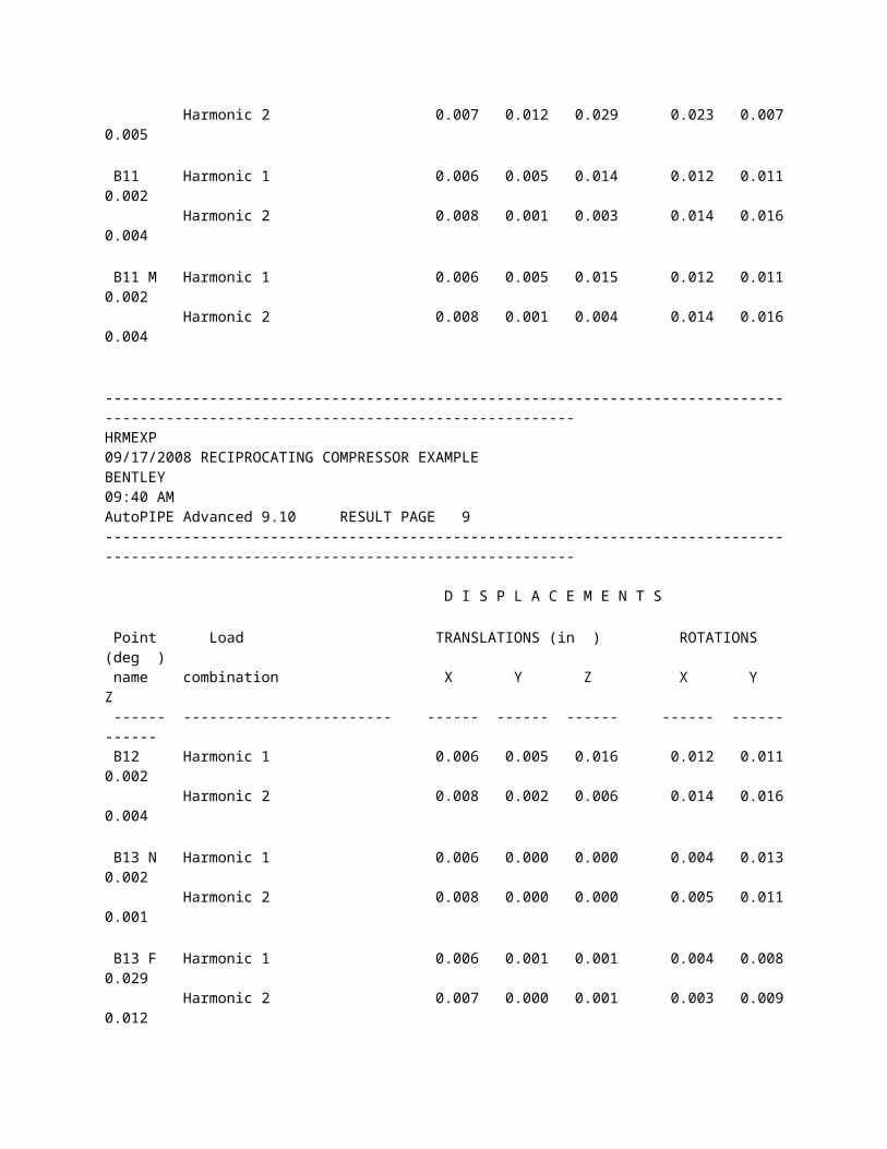
A81 Harmonic 1 0.208 0.000 0.053 0.021 0.010 0.019 Harmonic 2 0.053 0.000 0.023 0.010 0.013 0.004 A9 N Harmonic 1 0.208 0.042 0.014 0.024 0.060 0.034 Harmonic 2 0.053 0.017 0.005 0.009 0.028 0.015 A9 F Harmonic 1 0.192 0.043 0.000 0.031 0.130 0.024 Harmonic 2 0.048 0.017 0.000 0.012 0.036 0.010 A10 Harmonic 1 0.000 0.000 0.000 0.000 0.000 0.000 Harmonic 2 0.000 0.000 0.000 0.000 0.000 0.000 *** Segment A end *** *** Segment B begin *** A7 Harmonic 1 0.006 0.010 0.022 0.019 0.007 0.007 Harmonic 2 0.007 0.012 0.029 0.023 0.007 0.005 B11 Harmonic 1 0.006 0.005 0.014 0.012 0.011 0.002 Harmonic 2 0.008 0.001 0.003 0.014 0.016 0.004 B11 M Harmonic 1 0.006 0.005 0.015 0.012 0.011 0.002 Harmonic 2 0.008 0.001 0.004 0.014 0.016 0.004
------------------------------------------------------------------------------------------------------------------------------------HRMEXP 09/17/2008 RECIPROCATING COMPRESSOR EXAMPLE BENTLEY 09:40 AM AutoPIPE Advanced 9.10 RESULT PAGE 9------------------------------------------------------------------------------------------------------------------------------------
D I S P L A C E M E N T S Point Load TRANSLATIONS (in ) ROTATIONS (deg ) name combination X Y Z X Y Z
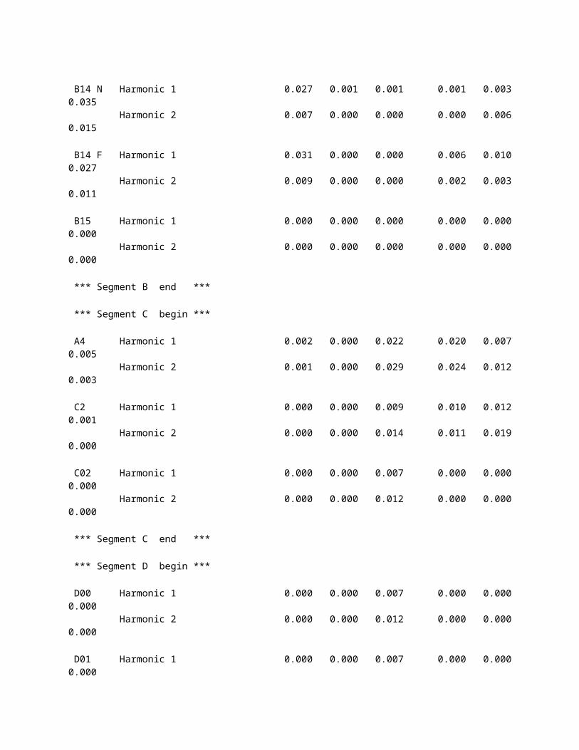
------ ------------------------ ------ ------ ------ ------ ------ ------ B12 Harmonic 1 0.006 0.005 0.016 0.012 0.011 0.002 Harmonic 2 0.008 0.002 0.006 0.014 0.016 0.004 B13 N Harmonic 1 0.006 0.000 0.000 0.004 0.013 0.002 Harmonic 2 0.008 0.000 0.000 0.005 0.011 0.001 B13 F Harmonic 1 0.006 0.001 0.001 0.004 0.008 0.029 Harmonic 2 0.007 0.000 0.001 0.003 0.009 0.012 B14 N Harmonic 1 0.027 0.001 0.001 0.001 0.003 0.035 Harmonic 2 0.007 0.000 0.000 0.000 0.006 0.015 B14 F Harmonic 1 0.031 0.000 0.000 0.006 0.010 0.027 Harmonic 2 0.009 0.000 0.000 0.002 0.003 0.011 B15 Harmonic 1 0.000 0.000 0.000 0.000 0.000 0.000 Harmonic 2 0.000 0.000 0.000 0.000 0.000 0.000 *** Segment B end *** *** Segment C begin *** A4 Harmonic 1 0.002 0.000 0.022 0.020 0.007 0.005 Harmonic 2 0.001 0.000 0.029 0.024 0.012 0.003 C2 Harmonic 1 0.000 0.000 0.009 0.010 0.012 0.001 Harmonic 2 0.000 0.000 0.014 0.011 0.019 0.000 C02 Harmonic 1 0.000 0.000 0.007 0.000 0.000 0.000 Harmonic 2 0.000 0.000 0.012 0.000 0.000 0.000 *** Segment C end *** *** Segment D begin *** D00 Harmonic 1 0.000 0.000 0.007 0.000 0.000 0.000
Harmonic 2 0.000 0.000 0.012 0.000 0.000 0.000 D01 Harmonic 1 0.000 0.000 0.007 0.000 0.000 0.000 Harmonic 2 0.000 0.000 0.012 0.000 0.000 0.000 C02 Harmonic 1 0.000 0.000 0.007 0.000 0.000 0.000 Harmonic 2 0.000 0.000 0.012 0.000 0.000 0.000 D03 Harmonic 1 0.000 0.000 0.007 0.000 0.000 0.000 Harmonic 2 0.000 0.000 0.012 0.000 0.000 0.000 D04 Harmonic 1 0.000 0.000 0.007 0.000 0.000 0.000 Harmonic 2 0.000 0.000 0.012 0.000 0.000 0.000 *** Segment D end ***
------------------------------------------------------------------------------------------------------------------------------------HRMEXP 09/17/2008 RECIPROCATING COMPRESSOR EXAMPLE BENTLEY 09:40 AM AutoPIPE Advanced 9.10 RESULT PAGE 10------------------------------------------------------------------------------------------------------------------------------------
D I S P L A C E M E N T S Point Load TRANSLATIONS (in ) ROTATIONS (deg ) name combination X Y Z X Y Z ------ ------------------------ ------ ------ ------ ------ ------ ------ *** Segment E begin *** E00 Harmonic 1 0.000 0.000 0.013 0.010 0.012 0.001 Harmonic 2 0.000 0.000 0.020 0.011 0.019 0.000 C2 Harmonic 1 0.000 0.000 0.009 0.010 0.012 0.001 Harmonic 2 0.000 0.000 0.014 0.011 0.019 0.000
E01 Harmonic 1 0.000 0.000 0.000 0.000 0.000 0.000 Harmonic 2 0.000 0.000 0.000 0.000 0.000 0.000 *** Segment E end ***
------------------------------------------------------------------------------------------------------------------------------------HRMEXP 09/17/2008 RECIPROCATING COMPRESSOR EXAMPLE BENTLEY 09:40 AM AutoPIPE Advanced 9.10 RESULT PAGE 11------------------------------------------------------------------------------------------------------------------------------------
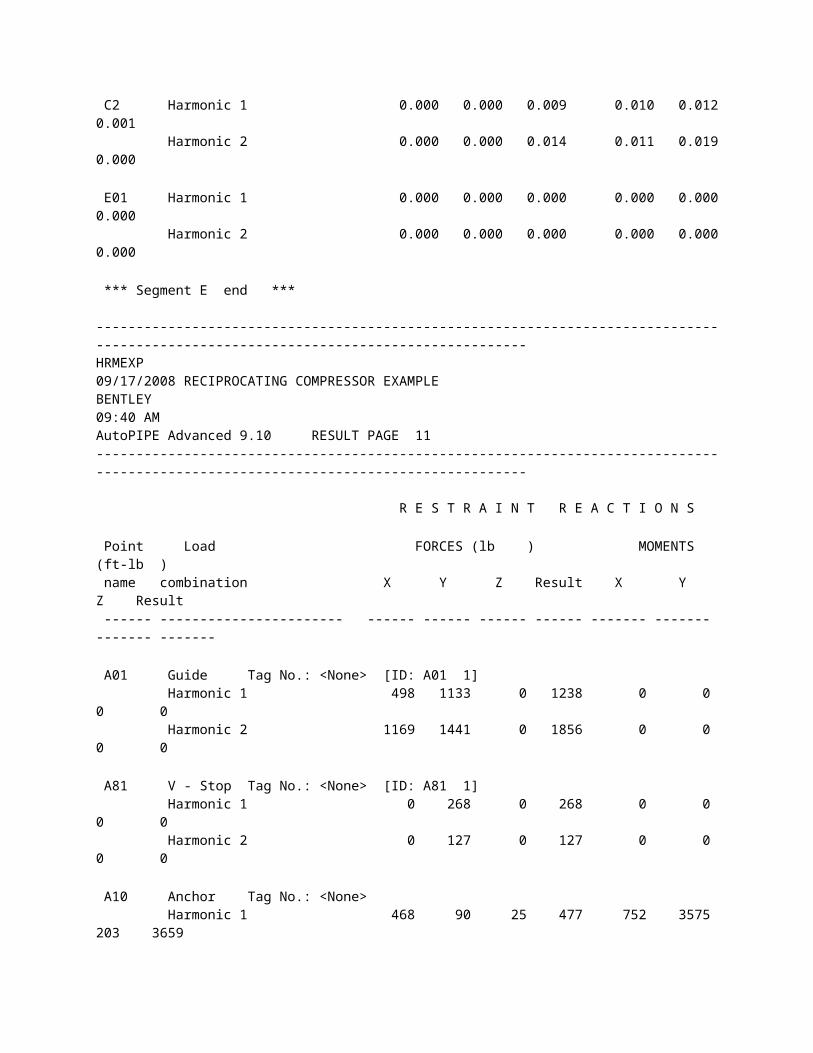
R E S T R A I N T R E A C T I O N S Point Load FORCES (lb ) MOMENTS (ft-lb ) name combination X Y Z Result X Y Z Result ------ ----------------------- ------ ------ ------ ------ ------- ------- ------- ------- A01 Guide Tag No.: <None> [ID: A01 1] Harmonic 1 498 1133 0 1238 0 0 0 0 Harmonic 2 1169 1441 0 1856 0 0 0 0 A81 V - Stop Tag No.: <None> [ID: A81 1] Harmonic 1 0 268 0 268 0 0 0 0 Harmonic 2 0 127 0 127 0 0 0 0 A10 Anchor Tag No.: <None> Harmonic 1 468 90 25 477 752 3575 203 3659 Harmonic 2 94 40 159 189 312 820 86 882 B13 N Guide Tag No.: <None> [ID: B13 N1] Harmonic 1 0 464 110 477 0 0 0 0 Harmonic 2 0 151 72 167 0 0 0 0 B14 F V - Stop Tag No.: <None> [ID: B14 F1] Harmonic 1 0 525 0 525 0 0 0 0 Harmonic 2 0 186 0 186 0 0 0 0
B15 Anchor Tag No.: <None> Harmonic 1 43 19 31 56 85 359 158 402 Harmonic 2 18 7 8 20 29 121 64 140 D01 Guide Tag No.: <None> [ID: D01 1] Harmonic 1 384 577 0 693 0 0 0 0 Harmonic 2 612 481 0 778 0 0 0 0 D03 Guide Tag No.: <None> [ID: D03 1] Harmonic 1 416 113 0 431 0 0 0 0 Harmonic 2 630 425 0 760 0 0 0 0 E01 Anchor Tag No.: <None> Harmonic 1 532 349 5078 5118 4835 18094 393 18733 Harmonic 2 262 267 7519 7529 5500 27421 432 27970
------------------------------------------------------------------------------------------------------------------------------------HRMEXP 09/17/2008 RECIPROCATING COMPRESSOR EXAMPLE BENTLEY 09:40 AM AutoPIPE Advanced 9.10 RESULT PAGE 12------------------------------------------------------------------------------------------------------------------------------------
ASME B31.3 (2006) CODE COMPLIANCE (Moments in ft-lb ) (Stress in psi ) Point Load In-Pl. Out-Pl. Torsion S.I.F Eq. Load Code Code name combination Moment Moment Moment In Out no. type Stress Allow. ------ ---------------------- ------- ------- ------- ---- ---- ---- ---- ------ ------ *** Segment A begin *** A5 Sus. + H1 0 0 1.00 1.00 (18) OCC 0 21277 Sus. + H2 0 0 1.00 1.00 (18) OCC 0 21277 A4 - Sus. + H1 1040 54 2.70 3.27 (18) OCC 191 21277 Sus. + H2 1133 516 2.70 3.27 (18) OCC 236 21277 A4 + Sus. + H1 4552 1235 2.70 3.27 (18) OCC 876 21277
Sus. + H2 5821 1286 2.70 3.27 (18) OCC 1102 21277 A6 Sus. + H1 3326 519 1.00 1.00 (18) OCC 228 21277 Sus. + H2 4051 1274 1.00 1.00 (18) OCC 287 21277 A0 Sus. + H1 2922 551 1.00 1.00 (18) OCC 4200 21280 Sus. + H2 3525 1210 1.00 1.00 (18) OCC 5264 21280 A7 - Sus. + H1 1080 1376 1.85 2.14 (18) OCC 5020 21280 Sus. + H2 942 1535 1.85 2.14 (18) OCC 5244 21280 A7 + Sus. + H1 1169 1439 1.85 2.14 (18) OCC 5309 21280 Sus. + H2 1861 1611 1.85 2.14 (18) OCC 6877 21280 A01 Sus. + H1 529 1590 1.00 1.00 (18) OCC 2366 21280 Sus. + H2 795 202 1.00 1.00 (18) OCC 1159 21280 A8 N- Sus. + H1 133 490 1.00 1.00 (18) OCC 717 21280 Sus. + H2 68 171 1.00 1.00 (18) OCC 259 21280 A8 N+ Sus. + H1 490 133 2.27 1.89 (18) OCC 1607 21280 Sus. + H2 171 68 2.27 1.89 (18) OCC 575 21280 A8 F- Sus. + H1 538 74 2.27 1.89 (18) OCC 1732 21280 Sus. + H2 282 51 2.27 1.89 (18) OCC 911 21280 A8 F+ Sus. + H1 74 538 1.00 1.00 (18) OCC 767 21280 Sus. + H2 51 282 1.00 1.00 (18) OCC 404 21280 A81 Sus. + H1 835 932 1.00 1.00 (18) OCC 1767 21280 Sus. + H2 391 1033 1.00 1.00 (18) OCC 1560 21280 A9 N- Sus. + H1 175 1011 1.00 1.00 (18) OCC 1449 21280 Sus. + H2 70 219 1.00 1.00 (18) OCC 325 21280
A9 N+ Sus. + H1 1011 175 2.27 1.89 (18) OCC 3268 21280 Sus. + H2 219 70 2.27 1.89 (18) OCC 726 21280 A9 F- Sus. + H1 756 90 2.27 1.89 (18) OCC 2432 21280 Sus. + H2 106 72 2.27 1.89 (18) OCC 388 21280
------------------------------------------------------------------------------------------------------------------------------------HRMEXP 09/17/2008 RECIPROCATING COMPRESSOR EXAMPLE BENTLEY 09:40 AM AutoPIPE Advanced 9.10 RESULT PAGE 13------------------------------------------------------------------------------------------------------------------------------------
ASME B31.3 (2006) CODE COMPLIANCE (Moments in ft-lb ) (Stress in psi ) Point Load In-Pl. Out-Pl. Torsion S.I.F Eq. Load Code Code name combination Moment Moment Moment In Out no. type Stress Allow. ------ ---------------------- ------- ------- ------- ---- ---- ---- ---- ------ ------ A9 F+ Sus. + H1 90 756 1.00 1.00 (18) OCC 1076 21280 Sus. + H2 72 106 1.00 1.00 (18) OCC 180 21280 A10 Sus. + H1 752 3575 1.00 1.00 (18) OCC 5160 21280 Sus. + H2 312 820 1.00 1.00 (18) OCC 1239 21280 *** Segment A end *** *** Segment B begin *** A7 Sus. + H1 701 92 1.85 2.14 (18) OCC 1855 21280 Sus. + H2 942 114 1.85 2.14 (18) OCC 2488 21280 B11 Sus. + H1 201 530 1.00 1.00 (18) OCC 801 21280 Sus. + H2 142 444 1.00 1.00 (18) OCC 658 21280 B12 Sus. + H1 228 656 1.00 1.00 (18) OCC 981 21280
Sus. + H2 182 653 1.00 1.00 (18) OCC 958 21280 B13 N- Sus. + H1 178 153 1.00 1.00 (18) OCC 331 21280 Sus. + H2 86 71 1.00 1.00 (18) OCC 158 21280 B13 N+ Sus. + H1 178 153 2.27 1.89 (18) OCC 700 21280 Sus. + H2 86 71 2.27 1.89 (18) OCC 334 21280 B13 F- Sus. + H1 436 79 2.27 1.89 (18) OCC 1410 21280 Sus. + H2 198 71 2.27 1.89 (18) OCC 660 21280 B13 F+ Sus. + H1 79 436 1.00 1.00 (18) OCC 625 21280 Sus. + H2 71 198 1.00 1.00 (18) OCC 296 21280 B14 N- Sus. + H1 184 78 1.00 1.00 (18) OCC 283 21280 Sus. + H2 75 25 1.00 1.00 (18) OCC 112 21280 B14 N+ Sus. + H1 184 78 2.27 1.89 (18) OCC 625 21280 Sus. + H2 75 25 2.27 1.89 (18) OCC 249 21280 B14 F- Sus. + H1 173 209 2.27 1.89 (18) OCC 785 21280 Sus. + H2 58 115 2.27 1.89 (18) OCC 358 21280 B14 F+ Sus. + H1 173 209 1.00 1.00 (18) OCC 383 21280 Sus. + H2 58 115 1.00 1.00 (18) OCC 181 21280 B15 Sus. + H1 85 359 1.00 1.00 (18) OCC 522 21280 Sus. + H2 29 121 1.00 1.00 (18) OCC 176 21280 *** Segment B end *** *** Segment C begin ***
------------------------------------------------------------------------------------------------------------------------------------HRMEXP
09/17/2008 RECIPROCATING COMPRESSOR EXAMPLE BENTLEY 09:40 AM AutoPIPE Advanced 9.10 RESULT PAGE 14------------------------------------------------------------------------------------------------------------------------------------
ASME B31.3 (2006) CODE COMPLIANCE (Moments in ft-lb ) (Stress in psi ) Point Load In-Pl. Out-Pl. Torsion S.I.F Eq. Load Code Code name combination Moment Moment Moment In Out no. type Stress Allow. ------ ---------------------- ------- ------- ------- ---- ---- ---- ---- ------ ------ A4 Sus. + H1 3513 155 2.70 3.27 (18) OCC 4405 21280 Sus. + H2 4691 98 2.70 3.27 (18) OCC 5875 21280 C2 - Sus. + H1 1214 6800 1.00 1.00 (18) OCC 3381 21280 Sus. + H2 694 8686 1.00 1.00 (18) OCC 4266 21280 C2 + Sus. + H1 183 1965 1.00 1.00 (18) OCC 966 21280 Sus. + H2 54 3197 1.00 1.00 (18) OCC 1565 21280 C02 Sus. + H1 907 0 2.70 3.27 (18) OCC 1135 21280 Sus. + H2 345 0 2.70 3.27 (18) OCC 432 21280 *** Segment C end *** *** Segment D begin *** D00 Sus. + H1 0 0 1.00 1.00 (18) OCC 0 21277 Sus. + H2 0 0 1.00 1.00 (18) OCC 0 21277 D01 Sus. + H1 0 0 1.00 1.00 (18) OCC 0 21277 Sus. + H2 0 0 1.00 1.00 (18) OCC 0 21277 C02 - Sus. + H1 1010 672 2.70 3.27 (18) OCC 237 21277 Sus. + H2 842 1070 2.70 3.27 (18) OCC 282 21277 C02 + Sus. + H1 198 727 2.70 3.27 (18) OCC 165 21277
Sus. + H2 744 1101 2.70 3.27 (18) OCC 279 21277 D03 Sus. + H1 1 0 1.00 1.00 (18) OCC 0 21277 Sus. + H2 0 0 1.00 1.00 (18) OCC 0 21277 D04 Sus. + H1 0 0 1.00 1.00 (18) OCC 0 21277 Sus. + H2 0 0 1.00 1.00 (18) OCC 0 21277 *** Segment D end *** *** Segment E begin *** E00 Sus. + H1 0 0 1.00 1.00 (18) OCC 0 21280 Sus. + H2 0 0 1.00 1.00 (18) OCC 0 21280 C2 - Sus. + H1 3 165 1.00 1.00 (18) OCC 22 21280 Sus. + H2 3 293 1.00 1.00 (18) OCC 38 21280 C2 + Sus. + H1 1035 2295 1.00 1.00 (18) OCC 330 21280 Sus. + H2 641 2662 1.00 1.00 (18) OCC 359 21280 E01 Sus. + H1 393 18094 1.00 1.00 (18) OCC 2374 21280 Sus. + H2 432 27421 1.00 1.00 (18) OCC 3597 21280 *** Segment E end ***