
FORTY-EIGHT - West Coast Harley-Davidson: Harley-Davidson ...

Harley Davidson Tech. 1
1) Intro Dates.a) 883: started in early 1986 to presentb) 1100: started in late 1986 to late 1987c) 1200: started in early 1988 to present
(Case breather sportsters from 1986-1990, Iron sportsters from 1957-1985)
2) Compression Ratioa) 9:1 on ALL models
3) Rocker coversa) Big Twins (B/T) and Sportsters(XL) can be interchanged as a set
i) Top end breather covers must be used on top end breather motorsii) Print-o-seal gasket and inner cork or rubber (chimney) are the same for B/T and XLiii) All rubber gaskets from late 1989 till currentiv) XL rocker arms and shafts are the same as the B/T
4) Rocker arm play is 0.003” to 0.013” between rocker arm and rocker box (endplay!)
5) Bolts are hardened and CANNOT be replaced or mixed with unhardened bolts
6) Rocker shaft to Rocker box clearance for all XL’s is 0.0007” to 0.0022” (ID to OD clearance)
7) 9/16ths 18 tap is used to push out rocker arm bushings (from the opposite side) – then press in newbushings
8) Pushrod tubesa) 1986-1990
i) multipiece tubeii) both top and bottom seal against an o-ring
9) Cylinder Heada) Early 883 – egg shaped chamber and sand castb) Late 883 – round/hemispherical shaped chamber, die castc) 1986 to early 1987 1100 – egg shaped chamber, sand castd) Late 1987 1100 and all 1200 – round/hemispherical shaped chamber, die caste) Late 1100 heads were milled 0.040”
i) That milling did not continue on the 1200
Torque pattern ààà Front cylinder _________ 1 | 3 |1/8th turn at a time | | 2 | 4 | --------------
Torque to 7ft/lb, then 14ft/lb Rear cylinderThen turn ¼ turn (90degrees) _________ 2 | 4 | | | 1 | 3 | --------------

10) Early head bolts have large spacers, later ones have a flange built onto the stud (changed 90/91)a) Lightly oil bolt after cleaning – used as anti-seize
11) Rocker arm bolts – longer bolt is on the pushrod side
12) Valvesa) 883 has the smallestb) 1100 from 1986 to early 1987 were the same as the B/T (1340) valvesc) 1100 in late 1987, decreased diameter of valves
i) Late 87 1100 and all 1200 valves are the same sizeii) The change resulted in better mid-range
d) XL’s have longer valve stems than B/Te) There are no service values available
13) Cylindersa) Different castings between the 3 different motors
i) 883, 1100 and 1200 stamped into bottom right corner of cylinderii) cylinders are all the same length and use the same sleeveiii) sleeve is just bored out more for the larger displacement
(1) stock bore(a) 883 – 3.00”(b) 1100 – 3.35”(c) 1200 – 3.50”(d) 883 can be bored out to 1200
14) pistonsa) Karl Schmidt (German)b) 1986 to early 1989 – no offset on piston for 883 and 1100 – install either directionc) late 1989 to present – 883 and 1200 pistons have offset with the arrow on piston crown facing
forwardd) As of October, 1994 – 883 pistons are coated with Teflon for break-in
15) Piston pina) 883 is shorter than 1100 or 1200 (diameter is the same)b) 1200 same 1340, but are NOT interchangeablec) 1200 have either ‘12’ or a ‘V’ grove stamped on the edge
16) Tappetsa) XL same as B/Tb) No restrictor on Early 1986c) Ristrictor added Late 1986-1990
i) Reduces oil to the top endii) Helps keep lifter filled at highway speeds (hydraulic lifters as opposed to solid)
d) Tappet working ranges
17) Tappet block – 4 speeda) To remove from case, turn tappet block and lift from caseb) Tappet to block fit
i) 0.0008” to 0.0023”ii) 0.003” service weariii) there are no stock oversizes available
c) new o-rings are made from silicone rubber and will swell when exposed to oild) oil leaks
i) tappet block to case – oil will be ‘grungy’ii) small o-ring to case – oil will be dirt-free; possible that the counterbore is to deep in the case
(should be 0.050” – 0.060”)
iii) shim up with a small washeriv) use Hylomar to seal
e) Torque to 15-18 ft/lbs
18) Gearcase covera) Bolt torque patterns given in Tech Tips 25b) 2 dowel pins are for centering coverc) computerized sizes for gear fitment
i) quadrex – room temp of 68 degreesii) measures center to center of bushings down to 0.00000 (hundred thousandths)iii) prints sheet telling what cams to useiv) production covers have no markings, but information is on file at HDv) P&A covers are color coded for correct cam selection
(1) PN – 25488-86 – cover with cams and pinion gear (‘T’ cams)(2) Cover only retrofits all alternator covers - 84 ½
d) Service of gearcase areai) Replace cover? – order cover and cams as a setii) Replace bushings?
(1) Must line ream
19) Camsa) 1986-1987 – ‘T’ cams
i) same cam in 883 and 1100ii) dogbone installed with the chamfer facing cam (out)
b) 1988-1990 – ‘C’ camsi) same cam used in 883 and 1200ii) reduced emissionsiii) dogbone installed with chamfer facing cam (out)
20) flywheelsa) 3 piece flywheels
i) 1 piece flywheel halvesii) no retrofit except left side wheel from pre-comonized to comonized – must rebalance
b) oil restrictor in the pinion shaftc) no rear cylinder advance markd) balance factors (used to balance at speed – higher % = balance at higher RPM, lower % = lower
RPM balance)i) 1340 – 60%ii) 1100 – 69% (blue)iii) 883 – 62% (yellow)iv) 1200 – 62% (white)v) after 1989, all 883 flywheels are colored green and all 1200’s are red
e) 1991 and later, there’s a timing mark on right side flywheel

21) Connecting rodsa) Dog legged (1982 and later – ALL Evos)b) Wrist pin clearance is 2 times that of a B/T, helps prevent seizurec) Bearings
i) Early 1986 were loose rollers with flat thrust washersii) Late 1986 through current use F.A.G. bearings (started on day 095)
d) For the first 2 months, no thrust washers were used; added late Mayi) Stepped for clearance; wider cage
e) Service just like the B/T bearingsi) 1 bearing size, 3 sizes of crank-pin
22) Sprocket Shafta) 5-speed shaft is 0.750” longer than 4-speed
i) Rotor and stator moved to sprocket shaft from clutch shellii) Rotor pressed and screwed to socket
23) Pinion shaft and racea) 1986 only – unitized (caged) bearing pressed into case
i) Race pressed onto shaft 1.185”-1.195” from flywheel raceii) Grind to size: 1.2485”-1.249”, 16rms finish
b) 1987-current uses F.A.G. bearingi) 3 pieces
(1) outer race pressed into case(2) inner race pressed onto shaft(3) separate bearings
ii) 4 sizes of bearingiii) races press to different depths, see service manual
c) 1988 to current – pinion shafti) Pinion shaft is straight, no splinesii) Pinion gear is light press fit and keyed to shaft
(1) Reduces gear runout = better cam fitiii) New pinion geariv) Nut has NO locktab so use locktite and torque to specs
24) Breather system – 4-speeda) Same as alternator iron XL engine
i) Plastic baffleii) Umbrella valve
b) Small hole under the valve to relieve oil buildup at breatheri) Hole must be open or air-cleaner will get oil
25) Oil pump – 4-speeda) Operation is the same as –77 pumpb) Feed gear height: 0.001’-0.011” above pump coverc) Feed gears were enlarged to supply lifters
i) Return gears are still larger than feedd) Gear clearance – inner and outer gear
i) Wear limit = 0.004”ii) Use shaft to center gears in body
e) Seal lip (numbers side) toward feed sidef) Oil pressure
i) Measure at the top plug in the case or the sending unit on the filter housing(1) Factory specs: 1-7psi at idle and 5-30psi at 2500 rpm(2) If taken at the sending unit, readings will be double
g) Oil flowi) Flows from oil tank to the pump cover

ii) Feed gear pressurizes oil through small hose to housing(1) Special hoses – 2 different fitting sizes, no sealant needed
iii) Oil filter adapter housing(1) Pressurized oil to adapter housing(2) Enters adapter through drilled holes and fills cavity(3) Builds 2-4psi, activates sending unit and oil light turns off(4) Cold oil pressure = high oil pressure(5) Pressure regulator bleeds off excess oil to gearcase; opens at 16-18psi(6) Regulator left out or stuck open = lifter collapse and oil pressure drop(7) Oil through filter to center of filter(8) Oil through check valve
(a) Opens at 4-6psi(b) Check valve creates backpressure, activates sending unit faster(c) Arrow on valve indicates direction of flow(d) Should point towards adapter with o-ring to the outside – counter bore(e) If installed backwards, it will damage the o-ring and create unfiltered path for oil
flow(f) Late 1987 has a new valve – rubber ball, spring and new fitting
(i) Ball to change in material and size; m-9501. Some sticking shut2. Also redesign of adapter
(g) 1992 production change; ball was changed again; has a tail; PN 33116-86Aiv) oil back to pump through large hosev) through pump and into engine case and gearcase covervi) first to lower end
(1) restrictor on pinion shaft reduces oil flow to rods(2) increases oil flow to top end
vii) path through gearcase cover and case sends oil to tappet blocks, lifters, pushrods and rockerarms
viii) all other areas are splash and drip
!! Iron heads – 80% oil to bottom end, 20% to top end !!!! Evo engines – 20% oil to bottom end, 80% to top end !!
ix) oil returns though cylinder drain holes and pushrod tubes(1) oil collects in mini-sump(2) oil collects in gearcase cover and drains into mini-sump
x) 3 things control oil return(1) spinning of flywheel and case scraper(2) downward action of the piston creating pressure in the case(3) suction of oil pump return gears
Harley Davidson Tech. 1
26) Intro Dates.a) 883: started in early 1986 to presentb) 1100: started in late 1986 to late 1987c) 1200: started in early 1988 to present
(Case breather sportsters from 1986-1990, Iron sportsters from 1957-1985)
27) Compression Ratioa) 9:1 on ALL models
28) Rocker coversa) Big Twins (B/T) and Sportsters(XL) can be interchanged as a set

i) Top end breather covers must be used on top end breather motorsii) Print-o-seal gasket and inner cork or rubber (chimney) are the same for B/T and XLiii) All rubber gaskets from late 1989 till currentiv) XL rocker arms and shafts are the same as the B/T
29) Rocker arm play is 0.003” to 0.013” between rocker arm and rocker box (endplay!)
30) Bolts are hardened and CANNOT be replaced or mixed with unhardened bolts
31) Rocker shaft to Rocker box clearance for all XL’s is 0.0007” to 0.0022” (ID to OD clearance)
32) 9/16ths 18 tap is used to push out rocker arm bushings (from the opposite side) – then press in newbushings
33) Pushrod tubesa) 1986-1990
i) multipiece tubeii) both top and bottom seal against an o-ring
34) Cylinder Heada) Early 883 – egg shaped chamber and sand castb) Late 883 – round/hemispherical shaped chamber, die castc) 1986 to early 1987 1100 – egg shaped chamber, sand castd) Late 1987 1100 and all 1200 – round/hemispherical shaped chamber, die caste) Late 1100 heads were milled 0.040”
i) That milling did not continue on the 1200
Torque pattern ààà Front cylinder _________ 1 | 3 |1/8th turn at a time | | 2 | 4 | --------------
Torque to 7ft/lb, then 14ft/lb Rear cylinderThen turn ¼ turn (90degrees) _________ 2 | 4 | | | 1 | 3 | --------------
35) Early head bolts have large spacers, later ones have a flange built onto the stud (changed 90/91)a) Lightly oil bolt after cleaning – used as anti-seize
36) Rocker arm bolts – longer bolt is on the pushrod side
37) Valvesa) 883 has the smallestb) 1100 from 1986 to early 1987 were the same as the B/T (1340) valvesc) 1100 in late 1987, decreased diameter of valves
i) Late 87 1100 and all 1200 valves are the same sizeii) The change resulted in better mid-range
d) XL’s have longer valve stems than B/Te) There are no service values available
38) Cylinders

a) Different castings between the 3 different motorsi) 883, 1100 and 1200 stamped into bottom right corner of cylinderii) cylinders are all the same length and use the same sleeveiii) sleeve is just bored out more for the larger displacement
(1) stock bore(a) 883 – 3.00”(b) 1100 – 3.35”(c) 1200 – 3.50”(d) 883 can be bored out to 1200
39) pistonsa) Karl Schmidt (German)b) 1986 to early 1989 – no offset on piston for 883 and 1100 – install either directionc) late 1989 to present – 883 and 1200 pistons have offset with the arrow on piston crown facing
forwardd) As of October, 1994 – 883 pistons are coated with Teflon for break-in
40) Piston pina) 883 is shorter than 1100 or 1200 (diameter is the same)b) 1200 same 1340, but are NOT interchangeablec) 1200 have either ‘12’ or a ‘V’ grove stamped on the edge
41) Tappetsa) XL same as B/Tb) No restrictor on Early 1986c) Ristrictor added Late 1986-1990
i) Reduces oil to the top endii) Helps keep lifter filled at highway speeds (hydraulic lifters as opposed to solid)
d) Tappet working ranges
42) Tappet block – 4 speeda) To remove from case, turn tappet block and lift from caseb) Tappet to block fit
i) 0.0008” to 0.0023”ii) 0.003” service weariii) there are no stock oversizes available
c) new o-rings are made from silicone rubber and will swell when exposed to oild) oil leaks
i) tappet block to case – oil will be ‘grungy’ii) small o-ring to case – oil will be dirt-free; possible that the counterbore is to deep in the case
(should be 0.050” – 0.060”)iii) shim up with a small washeriv) use Hylomar to seal
e) Torque to 15-18 ft/lbs
43) Gearcase covera) Bolt torque patterns given in Tech Tips 25b) 2 dowel pins are for centering coverc) computerized sizes for gear fitment
i) quadrex – room temp of 68 degreesii) measures center to center of bushings down to 0.00000 (hundred thousandths)iii) prints sheet telling what cams to useiv) production covers have no markings, but information is on file at HDv) P&A covers are color coded for correct cam selection
(1) PN – 25488-86 – cover with cams and pinion gear (‘T’ cams)(2) Cover only retrofits all alternator covers - 84 ½

d) Service of gearcase areai) Replace cover? – order cover and cams as a setii) Replace bushings?
(1) Must line ream
44) Camsa) 1986-1987 – ‘T’ cams
i) same cam in 883 and 1100ii) dogbone installed with the chamfer facing cam (out)
b) 1988-1990 – ‘C’ camsi) same cam used in 883 and 1200ii) reduced emissionsiii) dogbone installed with chamfer facing cam (out)
45) flywheelsa) 3 piece flywheels
i) 1 piece flywheel halvesii) no retrofit except left side wheel from pre-comonized to comonized – must rebalance
b) oil restrictor in the pinion shaftc) no rear cylinder advance markd) balance factors (used to balance at speed – higher % = balance at higher RPM, lower % = lower
RPM balance)i) 1340 – 60%ii) 1100 – 69% (blue)iii) 883 – 62% (yellow)iv) 1200 – 62% (white)v) after 1989, all 883 flywheels are colored green and all 1200’s are red
e) 1991 and later, there’s a timing mark on right side flywheel
46) Connecting rodsa) Dog legged (1982 and later – ALL Evos)b) Wrist pin clearance is 2 times that of a B/T, helps prevent seizurec) Bearings
i) Early 1986 were loose rollers with flat thrust washersii) Late 1986 through current use F.A.G. bearings (started on day 095)
d) For the first 2 months, no thrust washers were used; added late Mayi) Stepped for clearance; wider cage
e) Service just like the B/T bearingsi) 1 bearing size, 3 sizes of crank-pin
47) Sprocket Shafta) 5-speed shaft is 0.750” longer than 4-speed
i) Rotor and stator moved to sprocket shaft from clutch shellii) Rotor pressed and screwed to socket

48) Pinion shaft and racea) 1986 only – unitized (caged) bearing pressed into case
i) Race pressed onto shaft 1.185”-1.195” from flywheel raceii) Grind to size: 1.2485”-1.249”, 16rms finish
b) 1987-current uses F.A.G. bearingi) 3 pieces
(1) outer race pressed into case(2) inner race pressed onto shaft(3) separate bearings
ii) 4 sizes of bearingiii) races press to different depths, see service manual
c) 1988 to current – pinion shafti) Pinion shaft is straight, no splinesii) Pinion gear is light press fit and keyed to shaft
(1) Reduces gear runout = better cam fitiii) New pinion geariv) Nut has NO locktab so use locktite and torque to specs
49) Breather system – 4-speeda) Same as alternator iron XL engine
i) Plastic baffleii) Umbrella valve
b) Small hole under the valve to relieve oil buildup at breatheri) Hole must be open or air-cleaner will get oil
50) Oil pump – 4-speeda) Operation is the same as –77 pumpb) Feed gear height: 0.001’-0.011” above pump coverc) Feed gears were enlarged to supply lifters
i) Return gears are still larger than feedd) Gear clearance – inner and outer gear
i) Wear limit = 0.004”ii) Use shaft to center gears in body
e) Seal lip (numbers side) toward feed sidef) Oil pressure
i) Measure at the top plug in the case or the sending unit on the filter housing(1) Factory specs: 1-7psi at idle and 5-30psi at 2500 rpm(2) If taken at the sending unit, readings will be double
g) Oil flowi) Flows from oil tank to the pump coverii) Feed gear pressurizes oil through small hose to housing
(1) Special hoses – 2 different fitting sizes, no sealant needediii) Oil filter adapter housing
(1) Pressurized oil to adapter housing(2) Enters adapter through drilled holes and fills cavity(3) Builds 2-4psi, activates sending unit and oil light turns off(4) Cold oil pressure = high oil pressure(5) Pressure regulator bleeds off excess oil to gearcase; opens at 16-18psi(6) Regulator left out or stuck open = lifter collapse and oil pressure drop(7) Oil through filter to center of filter(8) Oil through check valve
(a) Opens at 4-6psi(b) Check valve creates backpressure, activates sending unit faster(c) Arrow on valve indicates direction of flow(d) Should point towards adapter with o-ring to the outside – counter bore

(e) If installed backwards, it will damage the o-ring and create unfiltered path for oilflow
(f) Late 1987 has a new valve – rubber ball, spring and new fitting(i) Ball to change in material and size; m-950
1. Some sticking shut2. Also redesign of adapter
(g) 1992 production change; ball was changed again; has a tail; PN 33116-86Aiv) oil back to pump through large hosev) through pump and into engine case and gearcase covervi) first to lower end
(1) restrictor on pinion shaft reduces oil flow to rods(2) increases oil flow to top end
vii) path through gearcase cover and case sends oil to tappet blocks, lifters, pushrods and rockerarms
viii) all other areas are splash and drip
!! Iron heads – 80% oil to bottom end, 20% to top end !!!! Evo engines – 20% oil to bottom end, 80% to top end !!
ix) oil returns though cylinder drain holes and pushrod tubes(1) oil collects in mini-sump(2) oil collects in gearcase cover and drains into mini-sump
x) 3 things control oil return(1) spinning of flywheel and case scraper(2) downward action of the piston creating pressure in the case(3) suction of oil pump return gears
PRIMARY DRIVE AND COVER
1. Clutch cable
A. sits below oil levelB. Hylomar on threadsC. copper washer under nutD. don’t damage o-ring (part of cable.no seperate part numberE. some cables leak at crimped area; replaceF. 88 clutch cable
1). o-ring at end2). adjustable in middle of cable3). 88 primary cover changed for o-ring4). cable will retro fit to 86
2. Clutch adjustment
A. disconnect batteryB. slacken clutch cable all the wayC. remove clutch screw lock and springD. turn counterclockwise until firmE. turn clockwise 1/4 to 1/2 turnF. replace screw lock and spring

G. adjust cable for1/16” cable freeplay
3. Primary chain adjustment
A. disconnect negative battery terminalB. take out slack in primary chainC. rotate wheel to find tight spotD. adjust to 3/8 to 1/2” slack
4. Oil level and type
A. H-D sport transmission fluid1). designed for higher loads2). retrofits all wet clutches
B. 4 speed1). 24 oz. measured2). fluid should just dribble out of level plug with motorcycle upright
C. 5 speed1). 32 oz. measured or just up to diaphragm spring on clutch
5. Cover removal
A. disconnect batteryB. release chain adjusterC. remove clutch screw nutsD. remove fasteners
6. Clutch release
A. powdered metalB. M-923 late model parts
1). angle of ramp and coupler changed, helps prevent breakage caused by misalignmentC. retro fits as set to 84 1/2
7. Motor sprocket and chain same since ‘57
A. torque to 150-160 ft-lbs. use Loctite 242B. use lock link tool to hold sprocket
8. Motor sprocket nut
A. it was first a grade 2 hex nutB. than a grade 5 hex nutC. now a grade 8 nut with a flange

D. torque to 150-165ft-lbs. Use Loctite 262
9. Source of oil leaks at primary
A. gasket surfaceB. shift shaft seal to coverC. foot peg shaftD. starter motorE. clutch cableF. screw adjuster
CLUTCH XL 4 SPEED
1. General
A. snap ring assemblyB. can be removed piece by piece or as a complete assemblyC. use a clutch spring compressor for disassembly
2. Clutch spring
A. diaphragm- same strength as old double coilB. special washers; round edge to spring
3. Clutch
A. fiber (friction)-drive1). .010” max warpage2). .130” minimum thickness3). when installing new, soak in oil for at least 5 minutes
B. steel-driven1). .010” max warpage2). .060” minimum thickness3). stamped steel, smooth rounded edge faces out
4. Spring plate
A. check for loose rivetsB. measure for variance; max. of .020”
5. Rotor
A. part of clutch shell assembly, magnets are fragile

6. Clutch hub bearing
A. beefed up L86, reduces looseness
ACCESS DOOR, XL 4 SPEED
1. Stator mount2. Torx screws
A. 30-40 in-lbs.B. loctite encapsulated on threads
3. Before removal, measure transmission shaft end play4. To remove access cover, shock dowel pins or heat around dowel pins
TRANSMISSION XL 4-SPEED
General
A. 4 SpeedB. Direct driveC. 1 to 1 ratio in 4th gearD. Sliding gearE. Sprocket: 21T, Right hand threads; 65-90 ft lbs
Check end play of main shaft and counter shaft before removing access door
Gear spacing can be accomplished by changing shift forks and/or spacer washers
A. Forks come in standard, +.005, + ,010, or + ,020 sizes. This changes spacing ofindividual sliding gears.
B. Different thickness washers used to adjust spacing of gears on countershaft.C. Use go/no go, method of spacing (in hand out)
Cam follower detent problems; M-949
A. L84 - E87 Steel zincB. M87 - L87 aluminumC. L87 - 90 aluminum w/counter bore
Mainshaft

A. 1st gear largest dia. gear1) M-934 recall 061
a) 87:28T gear, some break, switched back to -52A gear, 27T2) Radius on all 1st gears to case for lubrication.
a). press off/on with the bearing racesB. mainshaft 2nd and 3rd gears
1). same ratio since ‘572). 3rd gear end play reduced by thicker washer- running change 1986
a). will retro fit to 19573). M-906 late gears, smaller diameter
a). must be used on all 1100’sb). early or late model ok on 883c). prevents root contact caused by 1100 shaft flexingd). OK to mix early or late style on all xl models except 1100 or 1200
C. mainshaft 4th gear (clutch gear)1). needle bearing2). running 1986 thrust washer it has a loose fit
a). oil slots to the outside, don’t use3). 1987 ratio change
a). E-17Tb). L-18T, ID by groove in teethc). taller 1st through 3rd
D. Mainshaft1). .003” max bend2). check with freewheeling gears and V-blocks
6. Countershaft
A. 1st gear, smallest diameter gear1). needle bearings
B. Countershaft 2nd and 3rd gears1). same ratio since 19572). M-906, gear diameter reduced, running 1986
a). must be used on 1100b). early or late style ok on 883
C. Countershaft 4th gear1). step towards door-thrust washer2). 1987 ratio change
a). E-27Tb). L-26T, grove on face of gear
3). flip KM transmission plate overa). measure from end of splines to sliderb). use chart in manual to determine washer size
D. End play1). mainshaft = .006”-.020”, no preload

2). countershaft = .004”-.015”, use spoke to pull on shaft3). proceedure
a). install without washersb). measure end play and write it downc). use charts in manual to determine washer sized). reassemble and double check door bolt torque, 14 ft-lbs.
GENERAL
1. 66-69, generator bottom end. 70-84, AC generator (cone motor) (magnet spins around windings)
2. Installation of engine (right side)
A). rock motor corner to corner to check fit.B). torque down rear motor mountC). check front mount and frame for clearance (shim any clearance), than torque front
mountD). inspect clearance between top mount and frame. shim for “0” clearance, than torque.
3. Engine and tranny proceedure
A). install engineB). loosely bolt primary to engineC). with tranny and plate loose, bolt primary to trannyD). shim primary than torque engine and primary. than torque tranny and primaryE). torque tranny and plate
4. Rocker box installation torque pattern
5. Head bolt installation torque pattern
6. Rocker box
A. Cut out provides clearance between cover and frame when engine is hot1). engine expands approxamately .040” (measured from cylinder deck to top of rocker box).
B. Rocker shaft location, 1 degree negative angle places rocker arm lower on valve

side. spins valve to prevent lead build up, quieter, supposed to keep arm thrusted to one sideC. Gasket- torque to 12-15 ft-lbs. 300 percent increase when engine reaches operating temperature. assemble dry or with lithium grease (H-D says dry).D. Max warpage- .006”E. 78 1/2 late style rocker box. Boss under front for “ham can” mounting and
shortened boss on back left side using shorter stud.F. Rocker arms (2 types)
1). front exhaust/ rear intake and front intake/ rear exhaust2). case hardened, max wear or pitting, more than .005”, replace (pad or socket area)3). 66’-70’ rocker arms were copper plated (-66 arms)
71’-up, iron arm with more even wear (-66A arms, will retro fit)82’-up, had a ground out 1 degree to offset for negative angle in the cover(pad area)4). rocker arm end play
a). specs. .004”-.025” . Good is .004”-.010”b). alter end play
(1). best method, cut a shoulder on the shaft(2). good method, chamfer rocker arm spacer (5/8-3/4 countersink, 90 degree angle(3).bad method, shim the rocker arm (do not do this)
5). rocker shafta). -66A part number if o-ring seat is square. -66B part number if o-ring seat is
beveledb). specs. shaft to arm, .003” max clearance
shaft, .0015” max wearshaft to box, .002” max clearance
(1). excessive clearance in these areas will cause flooding of the valve pocket area.
c). see hand out page 3-1 for additional information
G. Pushrod1). all 4 identical2). inspect for:
a). damaged endsb). damaged locknutsc). max bend .010”
H. Pushrod Tubes1). 79’ and earlier, cork gasket, flat edge tube2). L79’-84 1/2’, o-ring gasket, lip edge tube. (for more compression, use cork in place of middle o-ring).
7. CYLINDER HEADS

A. Specs.1). head gasket surface, max warpage of .006”2). head gasket types, Teflon = blue, Graphite = black, Metal fiber = gray (James gasket with metal fire ring and silicon bead). Install all gaskets dry3). torque- 55-75 ft-lbs. staged, 30,45,55. (always start next to oil hole).
DO NOT GO OVER 65 FT-LBS. TOTAL, ALUMINUM.4). fire ring height causes leaking or blown head gasket when excessive .010” clearance between head and cylinder5). head bolt should be assembled with lube or “never seize”6). additional information on page 3-2 of hand out
B. Cylinder prep for re-assembly1). clean in soapy water2). clean and lube with a paper towel and motor oil (light weight)3). clean drain hole with a brush
C. 1980 heads1). cast iron guides, longer with shoulder2). head has machined surface for new style lower valve spring collar. collar now rests on head surface instead of valve guide shoulder3). L81
a). cst iron guides, longer with shoulderb). ream or hone for proper clearance, intake = .0015”, exhaust = .0025”c). valve guide seals- umbrella type seals
NOTE- do not use loctite on a valve guide seal
D. Valves1). hard valves- Eaton, hard chrome, US made.
Nittan, black nitride coating, Japan made.2). stem diameter- 80’ valve diameter same as earlier models. 81’ valve is
approximately .003” larger stem OD3). 80 and 81 valves are recommended for use with all cast iron guides4). medium hard valves, -57A and -66 valves are compatible with cast iron guides
but not recommended due to short service life5). soft valves, -57,-60 valves, never use soft valves with cast iron guides. (causes valve sticking).
E. Springs and hardware1). spring ID- silver = 82’ and earlier, red/orange = L82-84 (prevents coil bind with “S” cam)2). top retainer- mid 81 and earlier, thicker. L81 and up, .050” thinner for seal clearance3). bottom collar- 79 and earlier, 9/16 ID. sits on guide shoulder
L81 and up, 3/4 ID. fits over seal, sits on head surface

F. Cylinders. cast iron all years. 1200cc = 3 7/16 bore. 1340cc = 3 1/2” bore.1). 66’ -78’,1200cc, 10 fins with a thin base. (available untill 80’ as an option).2). 78 1/2 and up, 1340cc, 9 fins with a thick base. (1200cc option)
a). base is cut out for triangle washers, round side faces down.3).when boring or honing, use torque plates and gaskets.4). cylinder inspection:a). base surface, .003” max warpage.b). wear limits, max clearance, .006” cylinder to piston (.0015”-.003” good)
max taper, .002” max out of round, .001”
c). finish #240 plateau ( when sizing cylinder, use torque plates and gaskets)
G. Pistons1). 60’-83’, Bohnalite, USA made, H-D machined, cast in steel strut (controls expansion), tin coated for break in, symetric, no wrist pin offset, wrist pin clips 72’-77’, spirolox and 77’ and up use Tru arc (pistons will be marked with -78 part number or “77” cast into piston). can use a spirolox in a Tru arc piston, but not the reverse.2). compression ratio:
a). 1200cc, high compression 8:1, FLH, (round dimple in crown)b). 1200cc, low compression 7.4:1, FL, (no dimple)c). 1340cc, high compression 8:1, FLH, (rough crown)d). 1340cc, low compression 7.4:1, FL, (smooth crown)
3). wrist pin (see service bulletin- hand out page 3-15)a).-74 pistons have lowered wrist pin locations for use with .030” shorter connecting rodsb). -53 and -55 pistons have higher wrist pin location for use with longer rods.
(-36 and -41A)4). piston clearance: .001”-.002” with a max of .006”5). Mahle pistons-L83’-84’
a). German madeb). very hard (12% silicone content)c). approximately 100 grams lighter than Bohnalited). wire type pin clip (use special Kent-Moore tool to install) gap at 12:00e). wrist pin offset closer to rear of piston
(1). arrow faces forward(2). lug (under skirt to left)(3). pin closer to rear
6). Mahle piston shapea). diamond turned process (barrel faced)b). can retro fit to all 1340cc shovel head enginesc). things in common with the EVO; rings, pins,clips. nly difference is shovel pistons are domed, Evo are flat top
7). ringsa). 3 piece oil control, 1340cc, Dec. 78 and later, 1200cc, Jan. 79 and later

b). 3 piece oil control set features:(1). top ring: barrel face(2). 2nd ring: reverse twist taper face, scrapes on the way down, twists and
hydroplanes on the way up(3). bottom ring: 3 piece, rails top and bottom, expander in the middle. less cylinder wall tension than 1 piece ring, faster break in)
(i). L78’ and earlier engines use 1 piece cast iron oil control ring and 2 chrome plated compression rings.
(4). 3 piece set will retro to earlier pistons
H. Tappet guides1). 4 variations
a).66’-76 1/2, 1 small drain hole, countersunk screw holesb). 76 1/2’-E81’, small drain hole, straight screw holesc). L81’-E82”, no drain holes, had spigot for evacuatord). L82’ and up, 2 transfer holes, no spigot
2). inspectiona). check for cracks (base of roller guides)b). check for wear (max .002” between tappet and guide)
3). mounting screwsa). 66’-77’, 1/4 X 24b). 74’-84’, 1/4 X 20
4). updatinga).drill both drain holes through to the bottom with a 3/32” bit (or use 1/8”)
I. Tappets (same all gears)(not including hydraulic units)1). install with flat sides facing each other.
a). failure to install properly will prevent the exhaust from pumping up2). inspection: .001” max tappet wear, and .0015” max roller bearing clearance
a). inspect tappet screen every time you change oil (open end down, spring over screen)
J. Hydraulic lifter1). lifter test
a). dissassemble lifter unit, bleed and clean with contact cleanerb). with unit dry, manually compress and hold for 6 seconds, when released, plunger should pop up
2). lifter problem causesa). oil pressure, need a minimum of 12 PSI at 2000 RPMb). oil path restriction, tappet screen blockedc). tappet installed backwardsd). gasket misaligned at tappet guide
3). install tappet guide with installation tool in back (use every time to align tappets with cam)4). similar noises often mistaken for lifter problems
a). excessive rocker arm end play

b). loose cam gear fitc). exhaust leakd). sticking valvee). bent pushrodf). worn tappet roller bearing
K. Cam, Breather, and Pinion Gear1).cam endplay must be measured before cover is removed2). breather gear endplay: using a new gasket , feeler gauge, and a straight edge. measure between straightedge and breather gear with the gasket in place. than subtract .006” for gasket crush. ideal endplay is .005”-.010”3). cam fitment (see hand out page 2-15)
a). ideal, straight, no lashb). loose fitment, = noise, clatterc). tight fitment = whined). gear tooth changes (cam, pinion, breather)
(1). E77’ and earlier, straight tooth profile(2). L77’ and later, curved tooth profile (machined ring on side of gear)
(i). 7 gear sizes identified by color codes(3). never mix old and new style cam, breather, or pinion parts
4). Cam typesa).”H” cam, E83’ and earlier. “S” cam, L83’ and 84’b). “S” cam, all parts and accessories, less duration than “H” cam, more mid range, quiter valve train (softer)
5). Gear inspectiona). lobes, discoloration and pitsb). bearing surfaces (change from INA to Torrington)c). teethd). dog ear washer (installed eats down, slant towards rear)
G. 58’-72’ One shot oiling system72’ and up, flat side bushing that lines up oil holes in the bushing with oil passage(constant oiling)
L. Solid lifter usage1). can ruin hydraulic type cam, it has no expansion ramp2). solid ype lifter cams need expansion (clearance) ramps to reduce shock on cam
lobes, tappet rollers, and valve stems3). solid lifters provide more cam lift than hydraulic lifters
M. Breather gear1). 66’-E77’, steel, straight tooth (small nipple end)2). L77’-E81’, steel, curved tooth (large nipple end)3). L81’ and up, Zytel plastic, curved tooth (uses 6 slot window)
N. Pinion and oil pump gear

1). pinion, 58’-E77’, full tooth gear with straight profile L77’-84’, half tooth gear with curved profile. color coded availability
2). inspection, space rcollar should have end playa). check oil pump drive gear installation, install so iinner chamfer faces flywheels
3). oil pump drive gear, 66’-72’, 5 tooth, 73’-84’, 6 tooth4). oil pump driven gear, 66’-72’, 25 tooth (5:1 ratio), 73’-84’, 24 tooth (4:1 ratio,
better), can retro fit as a set
O. Gear case cover1). 66’-69’, peanut style2). 70’-72’, cone style, one shot oil flow3). 73’-84’, cone style, full flow oil flow
P. Torque pattern for cam cover installation
Q. Cam timing
8. LOWER END
A. commonized and pre-communized parts (hand out page 2-16)commonized parts L81’ and later: service bulletin M829A1). reason for change, more economical to manufacture and better fit at taper
commonized pre-commonizedpinion shaft 90 degree to keyway 135 degreesright side flywheelcrankpin rear cyl. advance = lazy 8 no lazy 8
B. Changes to crankpin after commonized1). L81’-L82’, .140” center oil hole2). L82’-84, .090” center oil hole3). 84’ and up, large offset oil hole

C. Connecting rods1). 41’-73’, long rods, no longer available, if old style pistons are retained for use with new style short rods
a). piston to flywheel clearance must be checked at BDC (should be 1/8” min)b). compression ratio will be reduced from 8:1, to 7.6:1
2). 74’-82’, short rods with slot, .030” shorter, center to center3). 82’-E83’, short rods with hole4). L83’-84’, short rods offset with hole (dog leg rods), 10 times the fatigue resistance (reduces bend and twist), wider web on female rod. requires new flywheels with relief
9. Oil pump
A. oil type1). 40 degrees and lower 10/40 multigrade2). 40-80 degrees 20/50 multigrade3). 80 degrees and up 60 weight, extra heavy4). 80-95 degrees SAE 605). 95 degrees and up SAE 70
B. oil pressure1). measure at operating temperature, 180-220 degrees2). spec.: idle, 3-5 PSI, 2000 RPM, 12-35 PSI
C. Feed system1). gravity feed to “F” fitting on pump2). check valve: a 2-3 lb spring and ball seals pump and prevents drain down
when engine is not running (a leaking check valve causes tank drain down andblows oil out of breather on start up)
a). to repair, lap seat with bead blasted Evo pushrod end (it’s the same size as the check ball)
3). after engine is running, check valve opens and oil flows to tappet screen,lifters, and top end
4). lower end passasge opens at 5-10 PSI (regulating piston moves upward to open passage), oil flows through crank case and gear case cover to pinion
bushinga). oil flows through pinion shaft, right side flywheel and crank pinb). the oil lubricates the rod bearingsc). splash from rods lubes the pistons, pin bushings, and lower end bearings
5). relief passage opens at 12-18 PSI (L73’-81, oil directed to return side. L81’ and up, directed to feed side relief)6). hydrolocked oil (oil trapped above relief piston)L73’-80’, down tower to
return (ID, large cap), 81’-E82’,to gear case (ID, small cap), 80’ and earlier, had short piston and a rod to limit travel. L82’ has long piston to block relief hole when not running to prevent drain down. rod deleted, long piston is its own travel limiter. also, make a groove so oil can get to hydrolock passsage when retro fitting

D. Breather system1). pressures: positive, piston moving downward
negative, piston moving upwards2). function, oil movement
a). pistons move downward,breather valve window is open and flywheel area blows oil into the gearcase
(1). gearcase area, normally positive(2). cylinder area, normally positive (transfers through tappet guide holes)
b). when pistons move upwards, breather window closes and a negative pressure is created
(1). flywheel area, normally negativec). there is a push/pull effect which helps drain oil from the top endd). oil seperator (hole at bottom of breather trap, feeds to hole in breather valve bore at the 5 o’clock position, connects with breather trap area. holes align on negative pressure to draw oil from bottom of the trap)e). hole in breather valve at 9 o’clock position is for primary oil return and should create a minimum of 25” water vacuum in the primary at 1500 RPM with vent line pinched (dry clutch model)
3). crankcase vent fitting, located above oil pump, connects to oil tank to prevent excessive pressure or vacuum4). crankcase breather fitting, lowest fitting on back of case, connected to air cleaner to reroute vapors through the engine5). evacuator system, used on E81”-E82’ models, hose connected pushrod tube area to cylinders. system did not work- causing oil consumption, carbon
deposits, and pushrod tube leaks6). typical breather and return system problems cause oil carryover
a). return restrictionb). over filled oil tankc). leaking check valved). damaged breather valve or casee). seperator hole pluggedf). breather trap gasket leaking
E. Return system1). oil drains to bottom of gearcase2). thick gears (return) pick up oil3). oil returns to tank through fitting next to “F” fitting at top of pump4). oil may also flow through filter and cooler before returning to tank
F. Updates1). L82’ engine oil changes- reduce top end fitting to .090” ( do this to all shovels)2). drill the 2 holes through in the tappet guide3). oil pump return (hand out page 3-9)4). lip side of seal towards feed gears

10. Dry clutchA. 36’-84 1/2, dry multiplate with chain drive primary (oil feed/ oil retrieved by engine vacuum)
1). primary is oil fed, oil is retrieved by engine vacuum (25” water vacuum at1500 RPM, vent pinched)
B. friction plates, .020” max warpage, can be scuffed upC steel plates, .010” max warpage, scars 1/32” or more, replace. grove wear .020” maxD installation, friction plate first and last; crankcase seal installs lip in to keep
engine oil out of dry primary
11. Clutch adjustment dataA. flat plate shifter wet or dry clutch 13/16” measurementB. ratchet top shifter wet or dry clutch 1/2” measurementC. 5 speed wet clutch 3/4 turn out
12. AP wet clutchA. 84 1/2’-89’, with 4 and 5 speed transmissionB. lubricant- level bottom of clutch with motorcycle upright and level. Derby cover removed, fluid to bottom edge of diaphragm springC. type- H-D primary chain case lubricant, 1 1/2 quart, change every 5,000 milesD. primary housing- extra fasteners added for rubber mountin 85’ and 86’ for rigid mount engines
1). printo seal gasket2). primary vent through mainshaft and transmission vent, vent plugged = oil leak3). crankshaft seal installs lip lip side out to keep primary chain case lubricant
from going into the engineE. clutch adjustment
1). service, set up, check at 500 miles than every 5,000 miles2). proceedure:
a). disconnect batteryb). apply max slack to clutch cablec). loosen clutch screw and locknutd). inspect and adjust spring tension
(1). spring attitude = flat + .010”(2). spring tension adjustment:
(i). back out adjuster plate bolts 1/2 to 1 turn at a time(ii). note position of bolts (A,B, or C)(iii). change position as necessary(iv). replace bolts 1/2 to 1 turn, loctite 222 on bolts, and torque to 6.5-8 ft-lbs.
e). adjust clutch screw (5speed)(1). turn in until it touches(2). back out 3/4 turn and tighten locknut

f). adjust clutch screw (4speed)(1). turn to position clutch arm 13/16” from transmission top(2). tighten locknut
g). adjust cable to provide 1/8” to 3/16’ cable freeplay between cable end and lever bracket
F. diaphragm spring- installs convex outG. adjuster plate- provides three positions for spring attitude adjustmentH. pressure plate- release plate is held in with a tapered snap ring (installs with taper out)I. updates:
1). mid92’ parts and accesories change, adjuster plate no longer provides 3 positions for spring adjustment. suggest to use shims if necessary to space
outward
13. Clutch platesA. 6 driven plates
1). friction materialsa). STD: 84 1/2 to 8/4/86, no asbestos, heavy use could ruinb). screaming eagle type: 8/5/86 to 5/12/88, paper construction, much better frictionc). sintered bronze type: 5/13/88 to 89’ production, almost indestructable, some slippage with heavy use
2). service, minimum thickness .078”, max warpage .011”3). never wipe with rags or dip in solvent4). always oil new plates before installation
B. 7 driven plates (steels)1). -84A plates may not fit over -84 hub2). service: minimum thickness .044”, max warpage .011”. install with rounded side out (all plates should slide freely over the hub)
14. Clutch shellA. ring gear and sprocket are shrink fit (same slippage of ring gear noted on early productions)B. do not pry on shell fingers = breakage
15. Clutch hubA. pressed into hub bearing which is pressed into shell with clips for retentionB. installing and removing hub ruins bearingC. hub nut must be torqued (over tightening cracks taper area), torque to 50-60 ft-lbs. use loctite 242D. check key height, .119” maxE. clean taper with contact cleaner
F. updates:1). -84A hub, some problems noted in 91’ and 92’
a). runs eccentric to shaftb). not fully machinedc). splines to large for -84A steel plates
2). clutch problemsa). misadjustmentb). wrong lubricantc). low level lubricant
d). customers driving habits
16. Transmission (transmission top is removable in frame, must move oil tank)A. 4 speed , constant mesh, sliding gear, direct drive, 1 to 1 ratio in 4th gearB. history:
1). ‘36, 1st year of manufacture, ‘52-E79, drum type shifter (ratchet top), L’79-85,flat plate shifter
C. lubricant: H-D Transmission Lube(not sport transmission lube), semi-synthetic gear lube
1). good alternative: 84/140 hypoid gear oil2). quantity: 24 ounces,(3/4 quart)3). level indicator: motorcycle must be upright and level
a). allen plug on coverb).bottom of filler plug threads
D. venting: flat plate shifter, two holes in top cover1). oil leaks at clutch tower usually indicates overfill or vent plugged
17. Shifter mechanismA. shifter cam moves forksB. pawl arms move camC. pawl carrier holds armsD. pawl carrier springs recenter carrier after shiftE. shift shaft moves pawl carrier
18. InspectionsA. shifter plate inspections:
1). bent or worn more than .010”, replace2). check for smooth fimger movement3). do not re-use snap ring
B. pawl arm inspection:1). hook area wear2). pawl spring wear
C. pawl carrier inspection1). broken or out of place(causes limp shifter)

D. cam follower inspection:1). bad spring; ID, cad plated(too stiff), coil binds2). good spring; ID, black, P/N 34068-52
E. shifter shaft inspection1). popping out of groove, use washers to shim
19. SprocketsA. left hand threads
1). mainshaft- clutch hub nut and sprocket nutB. lock brake or lock in 2 gears to remove sprocket nutC. tab washer lock; ‘83 and earlier
1). early style lock, bend tab only once2). torque nut to 80-90 ft-lbs., and use locktite 262
D. allen lock; ‘83 and later1). torque nut to 80-90 ft-lbs,(120 max)2). allen screw location must prevent nut from loosening3). retro’s to all ‘80 models
E. sprocket types: dished, ‘36-’79, installs with dish towards transmission, ‘80-’85, flatF. sizes: 22-24T, Ok for clearance to tranny: 25-26T, may require machining the
case for clearance
20. Kicker coverA. spring and shaft, align tab at 5 o’clock positionB. kicker gear dowel, align at 7 o’clock position
1). when together in the case, the dowel and the tab are aligned
21. Starter clutch and outer gear has rectangular keywayA. starter clutch (gear), 2 ratios
1). early, 14T: discontinued2). late, 16T: more leverage
22. Shifter forksA. shaft; e clip, always replaceB. steel, all gears, -36 p/n, counter and main are differentC. fork blocks
1). ‘36-E’76, rounded, 1 notch2). L’76-E’79, square, 1 notch3). L’79-’85, square, 2 notches
D. nuts face towards each other,torque to 12 ft-lbs.E. nut locks, bend only once

F. shims adjust forks,= gear spacing (shims go between fork and block only!)G. shift finger rollers (top hats)
1).long- drum roller2). short- plate shifter, and the XL3). always replace
23. Countershaft (hand out page 3-14)A. ‘36-’77,threaded, 1 grove. ‘77-’79, threaded, 2 grooves. ‘80-’83, notchedB. max bend, .003”(runout), max wear, .001”C. 1st gera, free-wheeler, largest OD, half speed bushing, max clearance, .004” total.
1). thrust washer next on shaftD. 1st and 2nd gear shifter clutch, “new”, mounts in either direction, max backlash, .010”E. 2nd gear, free-wheeler, second largest OD, half speed bushing, max clearance, .004” totalF. countershaft cluster, 3rd and 4th gear, most expensive, speedo drive in between 3rd and 4th gearG. case race, heat case to press in
1). threaded, 1 groove shaft,shouldered race on kicker side, no shoulder on other race, use loose roller bearings2). threaded, 2 groove shaft is .005” smaller in OD, need different bushings, used with caged bearings3). notched shaft, same as 2 groove
24. MainshaftA. different lenght shafts, pushrods also
1). ‘36-’64, short, kickstart2). ‘65-’69, long, electric start3). ‘70-E’80, longer, AC generator4). L’80-E’84, same length, different diameter5). L’84-’85, longest, wet clutch
B. max bend, .003”, max wear, ..001”C. 1st and 2nd gear, fixed, pressed on (FL, early FX, and late FX)D. 3rd gear, free-wheeler, bearing offset (causes a little whine), steel on steel, always
replace clipE. 3rd amd 4th gear clutch, marked “high” on one side for correct installation, dog ramps should angle to point towards rear. max backlash, .010”F. 4th (main drive gear), free-wheeler, bushing clearance .004” (good .001”-.002”)
1). installation of bushing requires a special tool and the direction is important. spiral or closed groove end installs toward the seal. leave enough room for the seal (1/4”-5/16”). hone or ream to size2). endplay, L’77-’81, .0025”-.0135”; M’77 and earlier, and ‘82-’85, .010”-.025”

25. Drive gear area leaksA. to locate use solvent or kerosene in transmissionB. areas:
1). seal to case2). seal to spacer, polish spacer and check for grooving, install new seals, pre-lube
lip3). spline leaks
C. ‘82-’85, use p/n 11166 o-ring to seal splines, new spacer p/n (for use with o-ring),chain, 35079-84, belt, 35070-84
D. ‘81 and earlier, clean all parts with contact cleaner before assembly
26. Bearing changesA. ‘36-E’77, 44 loose roller bearings around main drive gear
1). available in STD. .0004” and .0008” over sizeB. M’77-’85, caged bearingsC. to change early countershaft free bearings to caged, you need:
1). late cluster gear2). late countershaft (threaded, 2 groove or notched)3). late case races
D. throw out bearing1). ‘36-M’75, automobile style bearing (best style)
2). M’75-’85, wafer style bearing, takes the same load as auto style bearing (won’t live with a constant load)(clutch adjustment is critical).
has a sheet metal oil slinger
Batteries
1. Penned in date on top (should not sit on shelf for over one year). see service bulletin M1020A. Number = yearB. Letter = monthC. Example: 8L = Dec. ‘88
2. Late model chart for battery coding (see hand out)3. Putting battery into service
A. Take off vent plugB. Remove cap farthest from vent, set on holeC. Install vent tube, blow in tube, it should move the capD. Check strength of the electrolyte, it should be 1.265-1.270E. Fill each cell with electrolyte to lowest level. set aside for 30 minutesF. Rock battery to release trapped air and fill to upper levelG. Charge battery at 1/10 amp hour rating until fully charged. full charge is 1.270-1.280 specific gravity
4. Battery typeA. 19 amp. black with yellow caps

B. 22 amp. white with green capsC. 32 amp. black with green caps
5. Battery dataA. Conventional, charge a minimum of 6 hours, max temperature of 113 degrees F.B. Low maintenance, charge a minimum of 12 hoursC. Check specific gravity of a battery after it has charged (let sit for a couple of
hours before checking)6. Battery charger type
A. Taper rate charger, 2,4,6,8 ratings. use 2 amp charge, after first hour it should indicate 1-2 amp chargeB. Christie fixed rate charger, good for bringing a dead battery back to life
7. Servicing a used batteryA. Visual inspection- case and terminalsB. Inspect battery carrierC. Check for sulphation and sediment flakingD. Connect battery, tight, clean connections, 2 finger method, use dialectric grease or
petroleum jelly on terminals1). loose connections cause voltage spikes that damage electrical components
8. Battery testingA. Check specific gravity with a hygrometer, full charge is1.270-1.280 at 80 degrees
1). for every 10 degrees hotter, add .004 points2). for every 10 degrees cooler, subtract .004 points3). max cell variance is .050 points
B. Load testing (wear safety glasses)1). formula: 1/2 the cold cranking amps2). minimum voltage at end of testing is 9.6 volts3). don’t test with a specific gravity of less than 1.2404). check for bleeding with a multimeter
a). VDC scaleb). negative lead to negative lead of batteryc). positive lead to each battery cap, bad is more than 2.2 VDC
5). voltage output (can be done with battery in bike)a). turn ignition, lights, and accesories onb). VDC scale, minimum of 11 volts at terminals
AIR FILTER SERVICING
1. Paper, tap lightly, blow it off with air (not more than 30 PSI)A. If filter is oily, it can be cleaned with soap and water
2. Foam, wash with a strong detergent than rinse. when dry, apply 1 tablespoon of oil toelement , squeeze in and use paper towels to soak up excess
3. Gauze (K&N), wash in a strong detergent than rinse, shake off and air dry (not air pressure). spray with light coat of K&N oil on outside until gauze is pink
4. Ham can order of assembly

A. Manifold to headB. Carburator to manifoldC. Air cleaner backing plate to carburatorD. Align and tighten support bracket “last” (prevents pulling manifold from heads which causes air leaks)
THROTTLE CABLE ADJUSTMENT
1. Lubricate cable with a light viscosity lubricant2. Insure proper routing of cables (not pinched or crimped)3. Pull open cable, with front end straight, open throttle wide open
A. Adjust pull open cable until crank on carb. just touches carb. stop, snug locknut4. Return cable, turn front end all the way to the right lock
A. Adjust pull closed cable to eliminate freeplay between outer cable and cablespring
B. Check throttle snap back in left, right and straight position (throttle must turn freely in any front end position)C. Carburator overflow hose must be routed away from exhaustD. Inspect fuel system for leaks or damage: hoses, fuel valve (lubricate)
VEHICLE INSPECTION
1. Around the vehicle inspection similar to PDI (Pre-Delivery Inspection). seeinspection hand out
A. Right rearB. Right sideC. Right frontD. Left frontE. Left sideF. Left rear
OIL CHANGE PROCEEDURE
1. School vehiclesA. Drain oil into a clean pan and refill tank with original oilB. R&R oil filter, reuse old filter
1). when tightening, turn oil filter1/3-1/2 turn after gasket contacts housingC. R&R tappet screens on big twins and clean (use modified snap-on drag link socket)
2. Real worldA. Drain oil from tank

1). drain hoses where used as early as ‘83 on XL’s2). all H_D’s have a drain plug or drain hose3). fill to proper level with clean oil
B. Oil filter, always lubricate rubber gasket before installationC. Do not install return side oil filter until system has been flushedD. ‘84 and later Xl engine is on the fuel side, install before starting with filter 1/2 full
of oil3. Refilling system
A. First, refill oil tank with recommended oilB. Start engine and run until clean oil exits oil filter housing (this flushes old oil out
of the lines and crankcase)C. Always replace drain plug gasket
CARBURATION
1. It is illegal to altercarb (remove tamper plug)A. It is legal to:
1). adjust slow idle RPM2). adjust fast idle RPM3). adjust float level4). adjust accelerator pump spring tension or pin setting5). adjust choke spring6). adjust idle mixture if screw is exposed
2. Idle mixture adjustmentA. Should be performed after ignition timing is set, valve train adjustment, air filter service, and spark plug inspectionB. Motorcycle must be at operating temperatureC. Proceedure: check manual for initial settings:
Bendix, ‘72-’73 XL and FL/FX 1 1/2 turns outKeihin, 2 turns out
1). set idle speed to 900 to 1100 RPM (left side carb)2). slowly turn mixture screw clockwise to lean out3). when rear cylinder firing faulters, stop turning screw4). turn screw counter clockwise 1/8-1/4 turn until rear cylinder fires approxamately 75-90% of the time5). adjust idle speed as necessary
IDLE MIXTURE SCREW(stock set up)
2 turns 1 1/2 turns 1 turnmore than this normal less than thisjet is too small initial setting jet is too big
3.Fast idle, Keihin, (adjust only with engine cold)A. Adjust idle for 1500 RPM when choke is in #2 position (right side of carb)

B. Misadjustment1). too little; no “fast” idle2). too much; overrides slow idle adjustment, engine “races”
4. Choke, cable adjustment provides full open/full closed settingsA. Keihin carbs provide spring tension adjustment, if spring is weak, choke plate will
open when cranking engine to start, will cause a lean mixture5. Air leak problems
A. Symptoms:1). erratic idle2). spit back through carb3). hesitation, surging4). poor performance,detonation5). slow return to idle
6. Air leak diagnosisA. Using contact cleaner, spary around manifold area, throttle shaftB. Air leaks produce a change in idle speed when contact cleaner is sucked in
DO NOT SMELL EXHAUST, IT WILL RESULT IN DEATHC. Commercial tools for air leak detection are: snap-on propane leak detector,
electronic air leak detector
PRIMARY DRIVE always have battery disconnected before opening primary drive
1. InspectionA. tight spots, check chain slack all the way around, more than 3/8” differance between tightest and loosest spot, replace chainB. corrosion, link damage, or heat damage, replace chainC. inspect adjusters for excessive wear, fastener tightness and bracket conditionD. oil levels: XL(on sheet), FL ‘65-’84 1/2, none
2. adjustmentA. XL, 3/8”-5/8” (chain link height)(use inspection cover)B. Big twin, 5/8”-7/8”
FINAL DRIVE
1. InspectionA. Replace any chain that shows:
1). any rust between rollers and side plates2). has battery acid corrosion3). has more than 1/2” differance between tight and loose spots4). has roller or side plate damage
5). measures longer than 12 7/8” for 20 links6). has kinks
B. Replace any sprocket that shows wear1). teeth should almost have square teeth, no hooks or fins
2. AdjustmentA. Always adjust at the tightest spotB. Measure chain alignmentC. With axle alignment tool, measure swing arm pivot to axle distanceD. With alignment tool attached to chain at rear sprocket, check alignment of chain
to gaugeE. By sighting chain for alignment between sprockets, chain deflection is checked at bottom strandF. Fasteners
1). torque axle nut and replace cotter pin2). snug axle adjuster screw and locknut3). readjust brake on mechanical brake models
3. Rear chain R&RA. Loosen rear axle nut and chain adjusterB. Bump wheel assembly towards the frontC. Remove the old master linkD. Attach the new chain with old master linkE. Pull old chain to feed new chain on to sprocketsF. Insure new chain is correct length
1). correct new length should put axle almost all the way forward2). chain can be shortened 2 links at a time with a chain breaker
a). grind staked ends of pins off appropriate links with a grinderb). use chain breaker to push pins out
G. Install new masterlink, squeeze side plates over pins, using vice grips and a small nut, install safety clip so closed end points toward direction of travel
BRAKE SYSTEM
1. InspectionsA. Master cylinder and linkage, damage or leakage, failure to return fully when released, or sponginess when applying pressureB. Perform a stationary test: squeeze lever or depress pedal as hard as possible to make sure the system will not leak or fail. make sure system releases and wheel turns freelyC. Check fluid for contamination and level: any problem with master cylinder
requires rebuilding or replacement. fluid change level should be 1/8” from top(withreservoir level)
D. Linkage inspection, damage, wear, non-stock partsE. Adjustment inspection, freeplay must exist in most brake systems
1). ‘81 and earlier front master cylinders should have some freeplay. ‘82 and later do not

2). ‘85 and earlier rear brake systems must freeplayF. Front master cylinder
1). ‘72-E’81, Lester, has built in freeplay2). L’83 and up, Kelsey Hayes, has no freeplay, internals are held in place by a
seal ring. 5 bore sizesa). ‘82 only had 3/4” boreb). ‘83-’95, had 5/8” bore on a single disc and 11/16” on a dual discsc). ‘96 and up had 9/16” on singles and 13/16” on duals
G. Rear master cylinders1). ‘58-E’79, Wagner Lockheed (cast iron)
a). ‘58-E’72, hydraulic drumb). ‘72-’79, disc brakes
2). ‘79-E’87, Kelsey Hayes, (aluminum), requires a minimum of1/32” freeplay,do not over torque
3). ‘80 and up, FLT, FXR, FXST, used remote reservoir, freeplay 1/32”4). cartridge type, very rarely have to rebuild5). L’87 and up, built in freeplay, replaceable cartridge
H. Hoses and lines1). damage, leaks and weather cracking2). check for bulging or swelling when system is pressurized3). replace any parts not in excellent condition
I. Calipers1). damage, leaks, worn pivot points, non-stock parts2). calipers must be free floating, fasteners tight3). pad condition, correct parts, damage, wear, uneven or less than 1/16” thickness
requires replacementa). 1/2” pad thickness is better
4). half shim goes between piston and pad, rotor must turn into cut in pad. fullshin goes between back side of caliper and pad
a). purpose of half shim is to clean rotor and padJ. Discs
1). damage: max warp, .008”, max runout, .008”, (dial indicator mounted to front fork leg and spin disc), thickness: minimum thickness is stamped on the rotor (check in at least four places, with no more than .002” variance)2). rotor is the only part with the part number stamped on it**hand-out pages 5-17 to 5-21, bulletins on brakes and pads**
K. Disc and pad setsDISC PAD
-73, mild steel organic-78, hard stainless semi iron, black (color)-79, very hard stainless semi iron , copper-84, very hard stainless, 11/12” rotor,semi iron, copper-84A, 30 hole, anti symmetrical semi iron, copper-94, softer stainless semi iron, gray

BRAKE FLUID
1. DescriptionDot 3, glycol based (clear), hygroscopic, eats paint and plastic, 5K miles, have no
markings, has 3/4 mark
Sep. ‘76, service internal components, cup inside master cylinder
Dot 5, silicone based (purple), aerates, won’t harm paint or plastic, 15K miles, 2 yellow and 1 white dots, has 750 mark
**note: when you have metal to rubber; use Dow Corning-44: for metal to metal, use anti-seize**
BANANA BRAKE
1. ‘72-E’80, caliper body is the same for front and rear, differance is in the piston2. 3 pistons = 3 retraction rates (color painted on pucks)
A. Plain- frontB. Red- front or rearC. Gold- rear (most retraction)
3. ChangesA. ‘77-’80, wave washer was added to aid in retractionB. ‘73-E’81, boomerang bracket was usedC. L’81-’84, “Y” bracket replaced boomerangD. L’80-’84, cut groove and put square ring in body (no longer in the piston, 1 retraction rate)
1). undercut determines rate of retraction
COMPRESSION TESTING
1. ProceedureA. Remove spark plugs and join wires together with 1 plug to prevent arcing and possible fireB. Open throttle to wide open positionC. Turn engine over until compression tester shows less than 5 psi increase per compression strokeD. Both cylinders should read within 10% of each otherE. Most H-D engines will produce 100 psi or more
2. Differance of more than 10% between cylinders or compression below 100 psi,should be diagnosed
A. Put 1 tablespoon of motor oil in cylinder and test again1). psi higher now?, rings are not sealing2). psi same ?, suspect valve or gasket sealing problem

PUSHROD AND TAPPET ADJUSTMENT
1. see tech 1 notes, check pushrod adjustment, than run engine and change oil
FRONT AND REAR SUSPENSION
1. Check for any loose fasteners, check for any damage2. Check for any noticable dampening3. Check for any fluid or air leaks
FORK STEM BEARING INSPECTION
1. Check for any looseness in bearings2. Check that front end pivots smoothly
A. cables should not be binding movement3. Check adjustment
A. FLT/FLHT, swing method1). disconnect clutch cable from handlebar2). support vehicle evenly off of the ground3). pull front end to left lock and let go, front end should swing past center twice and stop somewhere near center
B. All other models (except springer), use 1”-2” fall away method1). disconnect clutch cable and any other restrictive cables2). support vehicle evenly off of the ground3). put front end in balanced position4). set pointer for reference and move front wheel to the left and than to the right
a). note where the front end “falls away” in each direction5). left and right fall away marks should be 1”-2” apart
REAR SUSPENSION
1. There should be no noticeable side play in rear fork2. There are several types of rear fork bearing designs:
A. Tapered bearings require grease and adjustmentsB. Solid stainless plug and Teflon bushing requires no serviceC. Silicone rubber “clevblock” design requires no service
3. Always check torque specs’ on any fasteners4. 4-speed swing arm bearing adjustment proceedure
A. Remove everything from swing arm and let it hang freeB. Connect fish scale to axleC. Lift swing arm with fish scale, check weight (12-15 lbs.)

D. Torque pivot bolt to increase weight by 2 pounds
AIR ASSISTED SUSPENSION
1. FLT,FLHT,FXRT moselshave front and rear sysstemsA. Always check manual during service with no loss air gauge, see manual for specs’B. Check for leaks in 2 ways
1). loss of pressure as read on gauge2). using soap and water
2. Anti-dive checkA. Hold front brake, ignition off and bounce front endB. Hold front brake, ignition on, and bounce front end same amount. there should be
noticeable increase in spring tension
WHEEL AND TIRE INSPECTION AND SERVICE
1. Tires: wear, replace tire if wear pattern is uneven, wear bars are exposed, or vehicle handles poorlyA. Damage inspection, replace tire if sidewall shows damage such as cracks or puncture. replace tire if tread area puncture is sideways to carcas or puncture size is greater than1/4”. also inspect for correct mounting, bead seated evenly and tire rotation
2. Service, tire pressure should be set to factory specs’and should not exceed maximum listed on side wall
3. Wheels, spin wheel to inspect for any damage or out of trueA. Feel for bearing end play (.002”-.006”)B. Cast wheels, if out of true or cracked,replace
1). max runout radial = 1/32”, lateral, 3/64”C. Spoke wheels, check spoke tightness, each spoke should emit a high pitched ring when tapped, all spokes should sound the same
1). max runout radial and latera, 1/32”
MISC. LUBRICATION
1.Wheel bearing grease (can), p/n 99855-89, (cartridge), p/n 99856-92A. Except ‘80-’81 FLTB. Any taper bearingC. Any part with a grease fitting
2. H-D high temperature grease, p/n 99862-72A. Points cam
3. Anti seize, some brake caliper pins, axles, front brake lever pins, throttle sleaves4. Triflo/Lubit 8/Tufoil, teflon lubricant, p/n 94968-85TB, cables, bracket and leverpivot points, shift linkage, clutch lever, locks and hinges and fuel valves
IGNITION SYSTEMS
1. Battery point ignition (BPI)A. Spark plug condition
1). broken porcelain, detonation2). shiny black coating, oil burning3). dry black coating, rich condition4). yellow deposits, deposits burned to insulator
B. Coil wires1). plug wire
a). visual inspection of insulation for crackingb). terminal for looseness or corrosionc). trouble shoot for bad wire using water mist (wire will arc to ground)
2). primary wirea). terminals loose at coilb). bad connection of wire to terminal
3). Ignition coila). inspect for cracks at mounting areab). plug wire terminals and primary wire posts
C. Points/Condenser1). inspect contact points, replace if pitted across more than 1/3 of surface, replace
if any damage is noted or if rubbing block is worn2). always replace condenser when replacing points3). advancer mechanism, typical high wear areas, springs, pins, shafts, and
weights. typical damage area, small locating pin at cam pin2. Maintenance
A. Spark plug gaping1). bend side electrode to adjust2). do not use automotive style adjuster, use wire gauge3). adjust gap to, .028”-.032”
B. Advancer lubricant1). light adequate lubrication of all moving parts with anti-seize
C. Points cam lubrication1). light coating of H-D hi temp grease, p/n 99862-72
3.A. Rear cylinder fires firstB. Point cam, wide lobe = rear cylinder, narrow lobe = front cylinder
4. Ignition timingA. Point gap, set gap on wide lobe, .018”, check gap on narrow lobe, should be .018”, + .002”, if not, recheck advancer for wear or misalignment on cam
5. Static timingA. Set point gap on wide lobe, than check point gap on narrow lobeB. Time off of front cylinder advance, back engine 1/2” of piston travel to find front cylinder advance mark
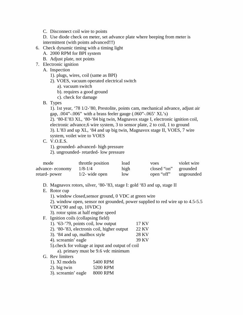
C. Disconnect coil wire to pointsD. Use diode check on meter, set advance plate where beeping from meter is intermittent (with points advanced!!!)
6. Check dynamic timing with a timing lightA. 2000 RPM for BPI systemB. Adjust plate, not points
7. Electronic ignitionA. Inspection
1). plugs, wires, coil (same as BPI)2). VOES, vacuum operated electrical switch
a). vacuum switchb). requires a good groundc). check for damage
B. Types1). 1st year, ‘78 1/2-’80, Prestolite, points cam, mechanical advance, adjust air gap, .004”-.006” with a brass feeler gauge (.060”-.065’ XL’s)2). ‘80-E’83 XL, ‘80-’84 big twin, Magnavox stage I, electronic ignition coil, electronic advance,6 wire system, 3 to sensor plate, 2 to coil, 1 to ground3). L’83 and up XL, ‘84 and up big twin, Magnavox stage II, VOES, 7 wire system, voilet wire to VOES
C. V.O.E.S.1). grounded- advanced- high pressure2). ungrounded- retarded- low pressure
mode throttle position load voes violet wireadvance- economy 1/8-1/4 high closed “on” groundedretard- power 1/2- wide open low open “off” ungrounded
D. Magnavox rotors, silver, ‘80-’83, stage I: gold ‘83 and up, stage IIE. Rotor cup
1). window closed,sensor ground, 0 VDC at green wire2). window open, sensor not grounded, power supplied to red wire up to 4.5-5.5 VDC(‘90 and up, 10VDC)3). rotor spins at half engine speed
F. Ignition coils (collapsing field)1). ‘63-’79, points coil, low output 17 KV2). ‘80-’83, electronis coil, higher output 22 KV3). ‘84 and up, mailbox style 28 KV4). screamin’ eagle 39 KV5).check for voltage at input and output of coil
a). primary must be 9.6 vdc minimumG. Rev limiters
1). Xl models 5400 RPM2). big twin 5200 RPM3). screamin’ eagle 8000 RPM

CHARGING SYSTEM
1. ComponentsA. BatteryB. StatorC. RotorD. Regulator
2. Quick test of charging systemA. Use meter across batteryon bike not running (check VDC)B. Recheck with bike running, voltage should increase 13.5-15 vdc (this is not conclusive)
3. Stator (coil of wire)A. To check stator, disconnect regulator, set meter to ohms, and check lead to leadB. Should have resistance, check manual for specs’C. Check for grounds, lead on stator to ground, should read OL (check both leads)D. Ac voltage output checks (checks the rotor)
1). set meter to vac, and place leads pin to pin2). run bike at idle and read meter3). run bike at 2000 RPM and read meter, reading should be double4). run bike at 3000 RPM and read meter, reading should be tripleidle =20 vac, 2000 rpm = 40 vac, 3000 rpm = 60 vac
E. Current draw1). set meter with red lead in 10 amp position2). turn on ignition, high beam, passing lamp, etc. (except brake light), read meter,
if under 7 amps, turn on brake light3). check total loads against total amps in charging system4). must have a minimum of 305 amps returning after loads to maintain battery
F. Regulator1). ground, from shiny edge of fin to to ground, should read OL2). system draw, “key off”, 10A scale, should read zero3). disconnect regulator lead at circuit breaker, so system drain test again
(minimal amount of drain ok)4). regulator bleed, check each pin, should be zero
WHEEL R&R
1. Key pointsA. Do not disconnect chainB. Remove chain or belt guardC. Don’t remove caliper assembly, compress piston by hand and tie up out of the
wayD. Don’t loosen chain or belt adjustersE. Remove axle, slide wheel forward,and remove air from tireF. Remove chain or belt from rear sprocket and remove rear wheel

G. On reinstallation, be sure brake pads are aligned properly before inserting brake discH. Recheck adjusters and adjust if necesary, chain or belt, alignment or tensionI. Pump brakes until firm, check for smooth release
2. ‘80-’84 FLT/FXRT (rear wheel removal)A. Raise rear wheelB. Remove both saddle bags and mulfflersC. Remove plug in tower chain housing, use long sheilded 3/8” allen socket, remove all 5 sprocket boltsD. Connect a ratchet strap to upper shock mount and swing arm, remove lower shock
bolts, lower swing arm enough to remove brake caliper anchor boltsE. Pull axle 3/4 of the way outF. Lift out caliper and hanger and secure out of the wayG. Deflate tire, seperate wheel from sprocket, tilt wheel, carefully removecaution- be careful of inner spacer falling out of wheel
3. InstallationA. Reverse order of removalB. Don’t forget the inner spacerC. Clean and lubricate boltsD. Torque sprocket bolts to 65-75 ft-lbs. cross patternE. Torque axle to 60 ft-lbs.F. Readjust caliper anchor boltsG. Mount mufflers forward on bracketH. Inflate tireI. Pump brakes