Hardware/Software Co-design and Verification Methodology from System Level … · 2008-04-16 ·...
30
Hardware/Software Co-design and Verification Methodology from System Level Based on System Dependence Graph Shunsuke Sasaki 1 , Tasuku Nishihara, Daisuke Ando, Masahiro Fujita (University of Tokyo, Japan {shun, tasuku, ando}@cad.t.u-tokyo.ac.jp, [email protected]) Abstract: System Dependence Graph (SDG) is a graph representation which shows dependencies among statements / expressions in a design. In this paper, we propose a new HW/SW co-design methodology based on SDG. In our method, any combination of C / C++ / SpecC descriptions is acceptable as input designs so that design functions can be specified flexibly. First, the input descriptions are analyzed and verified with static but partially dynamic program checking methods by traversing SDG. With those methods, large descriptions can be processed. Next, those designs are divided into HW and SW parts. In this step, SDGs are fully utilized to insert parallelism into the designs, and it enables flexible HW/SW partitioning. The HW parts are further optimized and then converted into RTL descriptions by existing behavioral synthesis tools. Finally, the generated RTL descriptions together with the SW parts are compared to the original descriptions in order to make sure that they are logically equivalent. Also, designer- specified properties may be model checked with these final design descriptions. Such formal verifications can be realized by translating those descriptions into Finite State Machine (FSM) type representations and existing formal verifiers. We show two case studies with practical examples to demonstrate the usefulness of our approach. Key Words: program slicing, hardware software co-design, hardware software co- verification Category: B.7.2, D.2.2, D.2.4 1 Introduction Due to the advances in VLSI and System-on-a-Chip (SoC) technology, the com- plexity of the fabricated chips is growing rapidly. The design and verification of SoC, however, do not catch up with such the quick growth. This makes the efficiency gap between the production and design / verification much wider, which is one of the key problems in today’s SoC design market. Now, new design methodologies which make the design and verification processes much more pro- ductive, are highly required. One of the most effective ways to improve design productivity is to start design from more abstracted levels. Recently, several system-level design languages which support IP reuse, such as SpecC [SpecC] or SystemC [SystemC], have been proposed. In system-level design, not only hardware (HW) development but also software (SW) development is taken care of. 1 Now at Toshiba Corporation Journal of Universal Computer Science, vol. 13, no. 13 (2007), 1972-2001 submitted: 30/9/06, accepted: 15/11/07, appeared: 28/12/07 © J.UCS
Transcript of Hardware/Software Co-design and Verification Methodology from System Level … · 2008-04-16 ·...

Hardware/Software Co-design and Verification
Methodology from System Level Based on System
Dependence Graph
Shunsuke Sasaki 1, Tasuku Nishihara,Daisuke Ando, Masahiro Fujita
(University of Tokyo, Japan{shun, tasuku, ando}@cad.t.u-tokyo.ac.jp, [email protected])
Abstract: System Dependence Graph (SDG) is a graph representation which showsdependencies among statements / expressions in a design. In this paper, we propose anew HW/SW co-design methodology based on SDG. In our method, any combinationof C / C++ / SpecC descriptions is acceptable as input designs so that design functionscan be specified flexibly. First, the input descriptions are analyzed and verified withstatic but partially dynamic program checking methods by traversing SDG. With thosemethods, large descriptions can be processed. Next, those designs are divided into HWand SW parts. In this step, SDGs are fully utilized to insert parallelism into the designs,and it enables flexible HW/SW partitioning. The HW parts are further optimized andthen converted into RTL descriptions by existing behavioral synthesis tools. Finally, thegenerated RTL descriptions together with the SW parts are compared to the originaldescriptions in order to make sure that they are logically equivalent. Also, designer-specified properties may be model checked with these final design descriptions. Suchformal verifications can be realized by translating those descriptions into Finite StateMachine (FSM) type representations and existing formal verifiers. We show two casestudies with practical examples to demonstrate the usefulness of our approach.
Key Words: program slicing, hardware software co-design, hardware software co-verification
Category: B.7.2, D.2.2, D.2.4
1 Introduction
Due to the advances in VLSI and System-on-a-Chip (SoC) technology, the com-plexity of the fabricated chips is growing rapidly. The design and verificationof SoC, however, do not catch up with such the quick growth. This makes theefficiency gap between the production and design / verification much wider,which is one of the key problems in today’s SoC design market. Now, new designmethodologies which make the design and verification processes much more pro-ductive, are highly required. One of the most effective ways to improve designproductivity is to start design from more abstracted levels. Recently, severalsystem-level design languages which support IP reuse, such as SpecC [SpecC]or SystemC [SystemC], have been proposed. In system-level design, not onlyhardware (HW) development but also software (SW) development is taken careof.1 Now at Toshiba Corporation
Journal of Universal Computer Science, vol. 13, no. 13 (2007), 1972-2001submitted: 30/9/06, accepted: 15/11/07, appeared: 28/12/07 © J.UCS

Program slicing is a technique which extracts portions related to a specifiedportion in a design [Weiser 1984]. It is originally developed in SW field, but alsoextended for HW field [Tanabe et al. 2004, Clarke et al. 1999]. This techniqueis known to be very useful in various ways for SW and HW development, e.g.program analysis, maintenance, debugging, test, and reuse. System DependenceGraph (SDG) is an intermediate graph representation for program slicing, andrepresents dependencies among statements / expressions in a design.
In this paper, we propose a HW/SW co-design methodology based on SDG.We use the SDG proposed in [Tanabe et al. 2004], and it can be created from anycombination of C / C++ / SpecC descriptions. In the proposed methodology,information of dependencies represented by the SDG is fully utilized for static(partially dynamic) code checking, parallelism extraction for HW/SW partition-ing, and formal verification.
This paper is the extended version of [Sasaki et al. 2006], and the followingpoints were refined from it.
– Deadlock and race condition detection methods were appended.
– The detail of the HW/SW partitioning method was described.
– Sufficient experimental results were appended.
The remainder of this paper is organized as follows. Section 2 introducesbackground knowledge on existing techniques used in our method and relatedworks. In Section 3, we give a proposed co-design methodology based on SDG.In Section 4, we show case studies of the proposed method by applying it toHW/SW co-designs of MPEG2 decoder and JPEG2000 encoder and demonstratethe usefulness of our approach. Finally, we conclude this work in Section 5.
2 Background
2.1 SpecC
SpecC [SpecC] is a system-level design description language, which is an ex-tension of ANSI-C language to describe HW parts of designs. In this section,we introduce the three main extensions in SpecC such as structural hierarchy,concurrency, and synchronization.
2.1.1 Structural Hierarchy
In order to describe structural hierarchies of target systems as classes in C++,behavior, channel, and interface are introduced in SpecC. A behavior has ports,component instantiations, private member variables and functions, and a publicmain member function. It can communicate with each other behaviors through
1973Sasaki S., Nishihara T., Ando D., Fujita M.: Hardware/Software Co-design ...

channels. An interface connects behaviors and a channel, and declarations ofcommunication methods, which will be defined in channels, are described. Oneadvantage of using SpecC is that designers can describe computation and com-munication separately.
2.1.2 Concurrency
Generally, statements in SpecC are executed sequentially from the top downas C / C++. Additionally, concurrent executions can be described in SpecCwith par statements. Statements directly under a par statement are executed asconcurrent processes.
2.1.3 Synchronization
Synchronizations among concurrent processes under a par statement can be rep-resented by wait / notify statements and event variables. For any event variablee, an execution of wait(e) suspends the execution of the process until notify(e)is executed in the other concurrent processes.
2.2 System Dependence Graph (SDG)
An SDG of a program is a graph where each node represents a statement andeach edge represents dependence between two statements. Dependence edges aremainly classified into data-dependence edges and control-dependence edges. Adata dependence edge is drawn from an assignment node N1 to another node N2
if an assigned variable at N1 can be used at N2 . On the other hand, a controldependence edge is drawn from a control point node N1 to another node N2 if theexecution of N2 is controlled by N1 (e.g. conditional branch). In addition, datadependence edges are labeled with the related variable, and control dependenceedges are labeled with ”true” or ”false”.
In [Tanabe et al. 2004], Tanabe et al. defined an SDG for SpecC descriptions.In the rest of this section, we introduce the detailed graph structures of theSpecC SDG. How concurrency and synchronization are represented in SDGs isalso introduced.
2.2.1 Nodes and Edges
Table 1 shows the nodes and edges in the SpecC SDG. They are defined basedon the SDG for C++ used in CodeSurfer[Grammatech] from Grammatech Inc.The nodes written in italic in the table were newly defined for SpecC.
1974 Sasaki S., Nishihara T., Ando D., Fujita M.: Hardware/Software Co-design ...

Table 1: Nodes and Edges of SpecC SDG.Elements(Additional element)
Nodes Entry Function / Behavior / Channel / Interface EntryAssignment Assignment, NotifyControl Point if, while, for, switch, case, par, wait, fsmCall Site Function Call, Instance CallActual Parameter Actual In, Actual Out, Global Actual In, Global Actual OutFormal Parameter Formal In, Formal Out, Global Formal in, Global Formal OutReturn ReturnDeclaration Declaration
Edges Control Control, CallData Data, Parameter In, Parameter OutDeclaration Declaration
par{b1.main();b2.main();
}
Statementpar
CallB1.main()
CallB2.main()
Formal Inp1
B1 B2
Formal Outp1
Control Dependence EdgeData Dependence Edge
Formal Outp1
Formal Inp1
Figure 1: Dependence graph of par.
behavior B1(event e){void main(){
notify(e);}
};
behavior B2(event e){void main(){
wait(e);}
};
Statementpar
CallB1.main()
CallB2.main()
Formal Ine
B1 B2
Formal Oute
Control Dependence EdgeData Dependence Edge
Statementnotify(e)
Statementwait(e)
Figure 2: Dependence graphs of wait and notify.
1975Sasaki S., Nishihara T., Ando D., Fujita M.: Hardware/Software Co-design ...

2.2.2 Concurrency
Figure 1 gives an example of an SDG including concurrency. A par statement isrepresented as a Control Point node, which is similar to if or while statement.Control dependence edges are drawn from the par node to child nodes. Allcontrol dependence edges from the par node are marked as true.
2.2.3 Synchronization
Figure 2 gives an example of an SDG including synchronization. A wait state-ment is represented as a Control Point node, and control dependence edgesare drawn from the wait node to all nodes before the next Control Pointnode. Also data dependence edges of event variables, which are the argumentsof notify nodes, are drawn to the wait node from a Formal In node. On theother hand, a notify statement is represented as an assignment node, and a datadependence edge of the event variable, which is the argument of the notify node,is drawn to a Formal Out node which corresponds to the output value of theevent variable from the behavior in which the notify node is. If synchronizationis properly taken with wait/notify, a data dependence edge of an event vari-able used in a notify node always reaches to the corresponding wait node viaFormal In / Out.
2.2.4 Program Slicing
Program slicing is a technique which extracts portions related to a specifiedportion in program codes. It is performed with SDG, and mainly there are threetypes of slicing techniques.
Backward slicing is a technique which extracts portions which affect a spec-ified portion in program codes. It is performed by gathering nodes passed whiletraversing dependence edges backwardly from the specified nodes.
Forward slicing is a technique which extracts portions affected by a speci-fied portion in program codes. It is performed by gathering nodes passed whiletraversing dependence edges forwardly from the specified nodes.
Chopping is a technique which extracts portions on the dependencies be-tween two specified portions in program codes. It is performed by extracting theintersection of forward slicing from one portion and backward slicing from theother portion.
2.3 Static Checking with Program Checker
For SW programs written in C/C++ , many program checkers have been devel-oped. To find bugs, data-flow analysis (DFA) is widely implemented in manytools like FlexeLint [FlexeLint], Coverity [Coverity], Fortify [Fortify], Orion
1976 Sasaki S., Nishihara T., Ando D., Fujita M.: Hardware/Software Co-design ...
[Orion] and UNO [Holzmann 2002]. These tools show suspicious portions in asource code to programmers as warnings. However, since DFA is static and doesnot consider functionalities, many false-negative warnings are reported. Thismakes it difficult for programmers to identify real bugs from a large number ofwarnings. To reduce false-negative warnings, some tools check feasibilities thatdetermine whether paths can actually be executed.
Compared with these checkers, our method can cover SpecC language, oneof the system-level description languages, as well as ANSI-C.
2.4 Hardware/Software Partitioning
Partitioning a system into HW and SW is one of the important steps in therefinement process from system level. This step has been researched as methodsto map tasks into HW and SW, and the complete optimization is known to bean NP complete problem. Recently, many researches for HW/SW optimizationare done by heuristics [Knerr et al. 2004, Wiangtong et al. 2002].
However, in commercial use, designers usually decide where to be as-signed to HW based on the results of performance estimation by simulation[Ueda et al. 2005]. One of the reasons why even though there are a lot of au-tomatic HW/SW partitioning method, they are not widely used in commercialuse, is that usually descriptions before HW/SW partitioning are not divided intomultiple processes.
Therefore, we propose a method to divide a sequential process into multipleconcurrent processes. Though our method does not change or optimize designbehaviors, after applying our method, existing partitioning methods can be usedmore effectively. The detail of this method is described in Section 3.2.
After applying the proposed method, we can apply existing HW/SW parti-tioning methods to find the best result to assign the concurrent processes intoHW and SW.
2.5 Formal Verification
Formal verification is the act of proving or disproving the correctness of a systemwith respect to a certain formal specification or property, using formal methodswhich are mathematically based techniques. Formal verification techniques canbe classified into model checking (property checking) and equivalence checking.
Model checking [Clarke et al. 1986, McMillan 1993, Brand 1993] is a tech-nique to algorithmically verify the model, often derived from a HW or SWdesign formally. This is achieved by checking if the model satisfies a logicalspecification (property). The property is often written as temporal logic for-mulae. Equivalence Checking [Brand 1993, Kuehlmann et al. 2002] verifies thefunctional equivalence of two designs that are at the same or different abstractionlevels.
1977Sasaki S., Nishihara T., Ando D., Fujita M.: Hardware/Software Co-design ...

Formal verification methods for high-level HW descriptions or sys-tem level descriptions are now in study phase. [Sakunkonchak et al. 2005,Moy et al. 2005, Grobe et al. 2003, Grobe et al. 2004] present model checkingmethods that verify SpecC or SystemC descriptions. [Sakunkonchak et al. 2005,Moy et al. 2005] are targeting on synchronization properties such as dead-lock. [Grobe et al. 2003, Grobe et al. 2004] check general properties written intemporal logic. Also, [Semeria et al. 2002, Clarke et al. 2003, Karfa et al. 2006,Saito et al. 2002, Matsumoto et al. 2006] show equivalence checking methods.
[Semeria et al. 2002, Clarke et al. 2003] check equivalences between behav-ioral level descriptions (ex. C descriptions) and Register Transfer Level (RTL)descriptions. In [Semeria et al. 2002], two descriptions are checked by a commer-cial RTL equivalence checker [Formality] after translating a behavioral descrip-tion into an RTL description. [Clarke et al. 2003] checks equivalence by usinga model checker as a verification engine. [Karfa et al. 2006, Saito et al. 2002,Matsumoto et al. 2006] check equivalence between two system level descriptionsby symbolic simulation. Symbolic simulation is a common technique in HW ver-ification and treats variables in descriptions as symbols rather than bit vectors.
Formal verification methods for RTL descriptions are matured technologiessupported by commercial SW tools [SLEC, Solidify, Formality].
3 Our Method
Figure 3 shows an overview of our method.Inputs of this method are any combinations of C/C++/SpecC descriptions,
so that designers can specify functions of the HW/SW systems more flexiblely.As the first step, the input descriptions can be analyzed and verified with
an SDG generated from the input descriptions. We give the details on this stepin Section 3.1. Also, the model checking methods [Sakunkonchak et al. 2005,Moy et al. 2005, Grobe et al. 2003, Grobe et al. 2004] introduced in Section 2.5can be applied as well in this step.
After the first step, we divide the systems into HW and SW parts afterintroducing parallelism. HW parts are synthesized into RTL descriptions. Thedetails are given in Section 3.2.
As the last step, the divided and synthesized HW parts and the SW parts arecompared to the original descriptions to check functional equivalence. Designerspecified properties can also be checked by model checkers at this step. Thedetails are given in Section 3.3.
3.1 Static Program Checking
First of all, we generate SDGs from the input design descriptions to analyze andverify them. In this section, we show several static program checking methods.
1978 Sasaki S., Nishihara T., Ando D., Fujita M.: Hardware/Software Co-design ...

Figure 3: Overview of Our Method.
Although some checking methods have been proposed for other dependencegraphs[Ferrante et al. 1987], those methods need to be re-discussed in this papersince our methods use SpecC SDG and can be used for system level designs whichcontain both HW and SW.
3.1.1 Detection of Unused Variables or Statements
Usually, each statement in design descriptions should have some influences onsome outputs. Statements which have no effects on outputs include bugs withhigh probability. In order to detect such statements, backward slicing can beused.
The algorithm is as follows:
1. Backward slicing from each output statement is performed.
2. The intersection of the results is computed.
1979Sasaki S., Nishihara T., Ando D., Fujita M.: Hardware/Software Co-design ...

behavior Main(in int x,in int y,out int z ){void main(void){
int sx, syint sxy; // Unusedsx = x * x;sy = y * y;sxy = x * y; // Unusedz = sx + sy;
}}
Statementsx = x*x
Statementsy = y*y
Statementsxy = x*y
Statementz = sx+sy
Forma Inint x
Formal Inint y
Variableint sx
Variableint sy
Variableint sxy
Formal Outint z
DeclarationDependence Edge
Data DependenceEdgeCriterion for
backward slicing
Figure 4: An example for detecting unused variables.
3. All nodes NOT included in the intersection have no effects on outputs, hencethese nodes indicate unused variables or statements.
Figure 4 gives an example source code and its SDG with an unused variable“sxy” and an unused statement “sxy = x * y”. Control dependence edges areabbreviated for simplicity. This example has an output port “z”. In SpecC lan-guage, inputs and outputs are clearly indicated as ports. The gray colored nodesin Figure 4 are included in the result of backward slicing from the output node“int z”. The node “int sxy” and the node “sxy = x * y” are not included in theresult of backward slicing, so we can detect them as unused variables/statements.
3.1.2 Detection of Uses of Uninitialized Variables
When the value of a variable is used in statements, the variable must be initial-ized before the executions of those statements. Uses of uninitialized variables areclassified into three types as given in Figure 5. In each case, a variable “a” isused at a statement “b = a + 5”. However, in (a), there are no nodes initializing“a”. In (b), though “a = 0” initializes “a”, it may not be executed since it isunder a conditional branch “if(cond)”. In (c), the execution order of “a = 0” and“b = a + 5” is not decidable when the behavior “B31” and “B32” are runningconcurrently. Therefore, “a” can be used before initializations in each case.
Uses of uninitialized variables can be detected by the following procedure.
1. For each variable used in a node, nodes where the variable is initialized arecollected by traversing data dependence edges backwardly.
2. Whether at least one of the initializing nodes is always executed before theusing node, is checked.
For example, a node “b = a + 5” in Figure 5 (b) is checked as follows.
1. A variable “a” is used in the node.
1980 Sasaki S., Nishihara T., Ando D., Fujita M.: Hardware/Software Co-design ...

Behavior B1(){void main(){
int a, b;b = a + 5;
}};
Behavior B2(){void main(){
int a, b;bool cond;if(cond) a = 0;b = a + 5;
}};
Behavior B31(int a){ Behavior B32(int a){void main(){ void main(){
a = 0; int b;} b = a + 5;
}; }};
Statementpar
CallB31.main()
CallB32.main()
Statementb = a+5
B31 B32
Control Dependence EdgeData Dependence Edge
Statementa = 0
B1.main()
B1
Statementb = a+5
B2.main()
B2
Statementb = a+5
Statementa = 0
Statementif(cond)
(a) (b) (c)
Figure 5: Classification of uses of uninitialized variables
2. Whether “a” is always initialized is checked.
(a) Data dependence edges about “a”are traversed backwardly from “b = a+ 5”, and “a = 0” which initializes “a” is found.
(b) Whether “a = 0” is always executed is checked.
i. Control dependence edges are traversed backwardly from “b = a +5” and “a = 0” to find the lowest common control node.
ii. Entry node “B2.main()” is found.
iii. “b = a + 5” is reachable from “B2.main()” along control dependenceedges.
iv. “a = 0” is NOT reachable from “B2.main()” without passing thecontrol node “if(cond)”.
v. Therefore, it is not guaranteed that “a = 0” is always executed.
(c) It is decided that “a” may be uninitialized.
Figure 6 gives the algorithm of this process with SDG.However, since the method described above does not interpret conditional
expressions in each node and decide that all paths are executable, some falsewarnings (which are actually not bugs) could be reported. Figure 7 gives ex-amples of false warnings. In (a), “b = a + 5” can be detected as an use ofuninitialized variables since “a = 0” is under a control node “if(1)”, although“a = 0” is always executed. On the other hand, in (b), ‘b = a + 5” also can be
1981Sasaki S., Nishihara T., Ando D., Fujita M.: Hardware/Software Co-design ...

N1, N2, N : nodes in SDGV : a variable in SDGforeach N1 in assignment nodes {
foreach V in variables used in N1 {foreach N2 in assignment nodes such that (
(N2 is reachable from N1 only with data dependence edge) and(V is defined at N2) ){
if exist N such that ((N is not ‘‘par’’ nor ‘‘if’’) and(N1 is reachable from N only with control dependence edge) and(N2 is reachable from N only with control dependence edge withoutpassing control node) ){
// variable V at N1 is initialized at N2next V
}}display warning message
}}
Figure 6: Pseudo-code of uninitialized variable checking algorithm.
detected as an use of uninitialized variables since “a = 0” and “a = 1” are undera control node “if(cond)”, although always either “a = 0” or “a = 1” is executed.Such false warning problems are solved by interpreting conditional expressions incontrol nodes and checking reachablities of initializing nodes formally by validitycheckers.
Figure 8 gives an algorithm to get a conditional expression to judge whetherthe target node is reachable (which means really executed). This method worksas follows :
1. Control / call edges are traversed backwardly until reaching a call-site of“main” function.
2. All conditional expressions of control nodes passed through are gathered,and their product is computed. (A control node “IF / ELSE” is consideredas “IF” when it reaches the node via control edge of “True”, in the othercase that reaches via “False”, it is considered as “ELSE”).
3. The satisfiability of the product is checked with a validity checker such asCVC[Stump et al. 2002].
The validity checker statically decides whether the condition is feasible bydecision procedure. If the condition is feasible, the node is judged to be reach-able, and it means that there are some input patterns with which a statementcorresponding to the node is executed. If the condition is not feasible, it is provedthat there are no input patterns with which the statement is executed. The re-sult is the same as that of trying all input patterns by simulation. Though themethod consumes more time than one simulation run, completeness of the resultis a big advantage.
1982 Sasaki S., Nishihara T., Ando D., Fujita M.: Hardware/Software Co-design ...

Behavior B1(){void main(){int a, b;if(1) a = 0;b = a + 5;
}};
Behavior B2(){void main(){
int a, b;bool cond;if(cond) a = 0;else a = 1;b = a + 5;
}};
Control Dependence Edge (true)
Data Dependence Edge
B1.main()
B1
Statementb = a+5
Statementa = 0
Statementif(1)
(a)
B2.main()
B2
Statementb = a+5
Statementa = 0
Statementif(cond)
(b)
Statementa = 1
Control Dependence Edge (false)
Figure 7: Examples of false warnings
With this method, the algorithm to detect uninitialized variables will beimproved. Figure 9 gives the pseudo-code of the algorithm. In this pseudo-code,a function “eval()” means “evaluates the argument predicate, and returns trueif the predicate is always satisfied”. In our implementation, we used a validitychecker CVC[Stump et al. 2002] to perform the function.
3.1.3 Detection of Null Pointer Dereferences
Null pointer dereferences happen when a pointer variable pointing nothing isdereferenced. Normally, pointer variables are used after initializations which as-sign addresses of something. Null pointer dereferences are classified into threetypes as given in Figure 10. In each case, a pointer variable “p” is used at “b= *p + 5”. However, in (a), there are no nodes initializing “p” except for “p =NULL”. In (b), though “p = &a” initializes “p”, it may not be executed sinceit is under a conditional branch “if(cond)”. In (c), the execution order of “p =&a” and “b = *p + 5” is not decidable when behaviors “B31” and “B32” arerunning concurrently. Therefore, “p” can be dereferenced as null pointer in eachcase.
Null pointer dereferences can be detected by the following procedure.
1. For each pointer variable used in nodes, nodes which initialize the pointerare collected by traversing data dependence edges backwardly.
2. Whether there are no nodes initializing to null is checked.
1983Sasaki S., Nishihara T., Ando D., Fujita M.: Hardware/Software Co-design ...

expression GetReachableCondition_Local(node V){expression result = "true";bool reach_end = false;
while(!reach_end){/* Traverse Control Dependence Edge Backwards */switch(getNodeType(V = ParentViaControlEdge(V))){
case ENTRY: // If it reaches to ENTRY node, finish.reach_end = true; break;
case IF:case WHILE:case FOR:/* Add the expression of the node to the result */result = (result && getExpr(V)); break;
case ELSE:/* Add negation of the expression of the node to the result */result = (result && !getExpr(V)); break;
case PAR:/* do nothing */result = result; break;
}}return result;
}
expression GetReachableCondition(node V){expression result = "true";bool reach_end = false;
while(!reach_end){/* Traverse Control Edge or Call Edge Backwards */switch(getNodeType(V)){
case MAIN_CALL_SITE: /* finish if call-site node of main() */reach_end = true; break;
default:result = (result && LocalReachability(V)); break;
}V = GetCaller(GetEntry(V)); /* Find caller of current function */
}return result;
}
Figure 8: Pseudo-code of an algorithm to get a conditional ex-pression.
For example, a node “b = *p + 5” in Figure 10 (b) is checked as follows.
1. A pointer variable “p” is used in the node.
2. Whether “p” can be null at the node is checked.
(a) Dependence edges about “p” are traversed backwardly from “b = *p +5”, and “p = NULL” and “p = &a” are found as nodes initializing “p”
(b) Since there is a node where “p” is defined to null, “p” is found to havea possibility to be null.
Figure 11 gives an algorithm of this procedure with SDG.In the null pointer dereferencing detection, the false warning problem men-
tioned in Section 3.1.2 may happen. Then, the reachability analysis techniqueproposed in Section 3.1.2 also can be applied to solve the problem.
1984 Sasaki S., Nishihara T., Ando D., Fujita M.: Hardware/Software Co-design ...
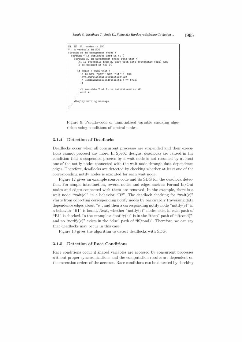
N1, N2, N : nodes in SDGV : a variable in SDGforeach N1 in assignment nodes {
foreach V in variables used in N1 {foreach N2 in assignment nodes such that (
(N1 is reachable from N2 only with data dependence edge) and(V is defined at N2) ){
if exist N such that ((N is not ‘‘par’’ nor ‘‘if’’) and(eval(GetReachableCondition(N2)-> GetReachableCondition(N1)) == true)){
// variable V at N1 is initialized at N2next V
}}display warning message
}}
Figure 9: Pseudo-code of uninitialized variable checking algo-rithm using conditions of control nodes.
3.1.4 Detection of Deadlocks
Deadlocks occur when all concurrent processes are suspended and their execu-tions cannot proceed any more. In SpecC designs, deadlocks are caused in thecondition that a suspended process by a wait node is not resumed by at leastone of the notify nodes connected with the wait node through data dependenceedges. Therefore, deadlocks are detected by checking whether at least one of thecorresponding notify nodes is executed for each wait node.
Figure 12 gives an example source code and its SDG for the deadlock detec-tion. For simple introduction, several nodes and edges such as Formal In/Outnodes and edges connected with them are removed. In the example, there is await node “wait(e)” in a behavior “B2”. The deadlock checking for “wait(e)”starts from collecting corresponding notify nodes by backwardly traversing datadependence edges about “e”, and then a corresponding notify node “notify(e)” ina behavior “B1” is found. Next, whether “notify(e)” nodes exist in each path of“B1” is checked. In the example a “notify(e)” is in the “then” path of “if(cond)”,and no “notify(e)” exists in the “else” path of “if(cond)”. Therefore, we can saythat deadlocks may occur in this case.
Figure 13 gives the algorithm to detect deadlocks with SDG.
3.1.5 Detection of Race Conditions
Race conditions occur if shared variables are accessed by concurrent processeswithout proper synchronizations and the computation results are dependent onthe execution orders of the accesses. Race conditions can be detected by checking
1985Sasaki S., Nishihara T., Ando D., Fujita M.: Hardware/Software Co-design ...

Behavior B1(){void main(){
int b;int* p = NULL;b = *p + 5;
}};
Behavior B2(){void main(){int a, b;int* p = NULL;bool cond;a = 0;if(cond) p = &a;b = *p + 5;
}};
Behavior B31(int* p){ Behavior B32(int* p){void main(){ void main(){
int a; int b;p = NULL; b = *p + 5;a = 0; }p = &a };
}};
Statementpar
CallB31.main()
CallB32.main()
Statementb = *p+5
B31 B32
Control Dependence EdgeData Dependence Edge
Statementp = NULL
B1.main()
B1
Statementb = *p+5
B2.main()
B2Statementb = *p+5
Statementp = &a
Statementif(cond)
(a) (b) (c)
Statementp = NULL
Statementa = 0
Statementp = &a
Statementp = NULL
Statementa = 0
Figure 10: Classification of null-pointer dereferences
N1, N2 : nodes in SDGp : a pointer variable in SDGforeach N1 in assignment nodes using pointer variables {
foreach p in pointer variables dereferenced in N1 {foreach N2 in assignment nodes such that (
(N1 is reachable from N2 only with data dependence edge of p)and(p is defined at N2)
){if ( p is defined NULL at N2 ){// pointer variable p at N1 has the possibility to be NULLdisplay warning message
}}
}}
Figure 11: Pseudo-code of null pointer dereference checking al-gorithm.
1986 Sasaki S., Nishihara T., Ando D., Fujita M.: Hardware/Software Co-design ...

Behavior B1(int x, event e){void main(){wait(e);x = 2 * x;
}};
Behavior B2(int x, event e){bool cond;void main(){x = 0;if(cond) notify(e);
}};
Statementpar
CallB1.main()
CallB2.main()
Statementwait(e)
B1 B2
Control Dependence Edge
Data Dependence EdgeControl Flow Edge (false)
Statementif(cond)
Statementx = 0
Statementnotify(e)
Control Flow Edge (true)
Statementx = 2 * x
EndEnd
Variableint x
Declaration Dependence Edge
Figure 12: An example for deadlock detection
whether each execution order of two nodes connected by data dependence edgesbetween concurrent processes is decidable or not.
In the race condition detection, we have to decide whether the executionorder of two nodes in concurrent processes is decidable or not. Here, we canassume that deadlocks do not occur, since we can find them by the deadlockdetection method proposed in Section 3.1.4. The conditions that a node “a” ina process “B1” must be executed before a node “b” in a process “B2” are asfollows (See Figure 14):
– There are notify nodes “n”s after “a” for all paths in “B1”.
– There are wait nodes “w” s before “b” for all paths in “B2”.
– All pairs of an “n” and a “w” are connected through data dependence edges.
– There are no notify nodes except for those “n”s connected to those “w”s bydata dependence edges. It guarantees that “B2” suspended by the “w”s isresumed only by the “n”s.
Figure 15 gives an example source code and its SDG for the race conditiondetection. In this case, there is a data dependence edge from “x = 0” in “B1”to “x = 2 * x” in “B2”. The race condition checking for the two nodes is carriedout as follows. First, with assuming that “x = 0” is always executed before “x= 2 * x”, whether at least one notify node exists in all paths of “B1” is checked.However, this assumption is found false since notify nodes do not exist in thepath after “x = 0”. Similarly, the assumption that “x = 2 * x” is always executedbefore “x = 0” is found false. Therefore, since the execution order of the twonodes is not decidable, we can say they are in race condition.
1987Sasaki S., Nishihara T., Ando D., Fujita M.: Hardware/Software Co-design ...

N1, N2, N3, N4, N5 : nodes in SDGe : a event variable in SDGforeach N1 in ‘‘wait’’ nodes {
foreach e in event variables used in N1 {foreach N2 such that(
(N2 is ‘‘notify’’ node) and(N1 is reachable from N2 only with data dependence edge of e)
){if (N2 does not exist){display warning messageNext e
}if((exist N3 such that
(N3 is ‘‘par’’ node) and(N1 is reachable from N3 only with control dependence edge) and(N2 is reachable from N3 only with control dependence edge) andnot (exist N4 such that
(N1 is reachable from N4 only with control dependence edge) and(N2 is reachable from N4 only with control dependence edge) and(N4 is reachable from N3 only with control dependence edge)
))and(exist N5 such that
(N5 is ‘‘if’’, ‘‘while’’ or ‘‘for’’ node) and(N5 is reachable from N3 only with control dependence edge) and(N2 is reachable from N5 only with control dependence edge)
)){display warning messageNext e
}}
}}
Figure 13: Pseudo-code of deadlock checking algorithm.
n
par
a
B1
b
w
B2
n
w Control Flow Edge
Data Dependence Edge
w
n
Wait Node
Notify Node
Figure 14: An example SDG for race condition detection
1988 Sasaki S., Nishihara T., Ando D., Fujita M.: Hardware/Software Co-design ...

Behavior B1(int x, event e){void main(){
wait(e);x = 2 * x;
}};
Behavior B2(int x, event e){bool cond;void main(){
notify(e);x = 0;
}};
Statementpar
CallB1.main()
CallB2.main()
Statementwait(e)
B1 B2
Control Dependence Edge
Data Dependence Edge
Control Flow Edge (false)
Statementx = 0
Statementnotify(e)
Control Flow Edge (true)
Statementx = 2 * x
EndEnd
Variableint x
Declaration Dependence Edge
Figure 15: An example for race condition detection
Figure 16 gives the algorithm to detect race conditions with SDG.
3.2 Hardware / Software Partitioning
After applying static checking methods to input descriptions, HW/SW parti-tioning is performed. As we mentioned in Section 2.4, though there are a lotof existing partitioning methods using heuristics, those methods can be appliedonly when designs have been divided into tasks(multiple procedures). Thosetasks can be considered as behaviors in SpecC descriptions. To apply such par-titioning methods flexibly, it is important to divide the designs into multiplebehaviors executed concurrently.
In this section, we propose a method to divide a behavior into multiple con-current behaviors by dependence analysis with SDG. In this method, parallelismis extracted via SDGs in a way such that two nodes can be executed in parallelwherever they don’t depend on each other. Also, even if two nodes depend oneach other, they can be assigned to separate concurrent behaviors by adding syn-chronization statements. This method can be applied to any sequential executionin a design.
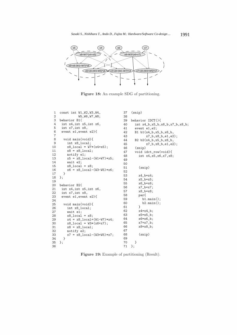
Figure 17, 18 and 19 give an example. In this example, lines 9 to 14 in Figure17 are the target to be divided. Figure 18 gives the SDG of this code (controledges are abbreviated).
We divide this code into two behaviors. Suppose “x8 = W7*(x4+x5);”, “x5= x8 - (W1+W7)*x5;”,and “x6 = x8 - (W3-W5)*x6;” are assigned to one be-havior, and others are assigned to another (This partitioning is very inefficient,
1989Sasaki S., Nishihara T., Ando D., Fujita M.: Hardware/Software Co-design ...

N1, N2, N3, N4, N5, N6, N7: nodes in SDGV : a variable in SDGforeach N1 in declaration nodes of shared variables {
foreach V in variables declared in N1 {foreach N2 and N3 in assignment nodes{
if ((N2 and N3 are not the same node) and(N2 and N3 has a data dependence about V) and(exist N4 such that
(N4 is ‘‘par’’ node) and(N2 is reachable from N4 only with control dependence edge) and(N3 is reachable from N4 only with control dependence edge) andnot (exist N5 such that
(N2 is reachable from N5 only with control dependence edge) and(N2 is reachable from N5 only with control dependence edge) and(N5 is reachable from N4 only with control dependence edge)
))and not(
((exist N6 such that(N6 is ‘‘wait’’ node) and(N2 is reachable from N6 only with control dependence edge)
)and(exist N7 such that
(N7 is ‘‘notify’’ node) and(Argument in N7 is the same as that in N6) and(N7 is reachable form N3 only with control flow edge)
))or((exist N6 such that
(N6 is ‘‘wait’’ node) and(N3 is reachable from N6 only with control dependence edge)
)and(exist N7 such that
(N7 is ‘‘notify’’ node) and(Argument in N7 is the same as that in N6) and(N7 is reachable form N2 only with control flow edge)
)))
){display warning messageNext pair of N2 and N3
}}
}}
Figure 16: Pseudo-code of race condition checking algorithm.
1 const int W1,W2,W3,W4,2 W5,W6,W7,W8;3 (snip)4 behavior IDCT(){5 (snip)6 void idct_row(void){7 int x4,x5,x6,x7,x8;8 (snip)9 x8 = W7*(x4+x5);
10 x4 = x8 + (W1-W7)*x4;
11 x5 = x8 - (W1+W7)*x5;
12 x8 = W3*(x6+x7);
13 x6 = x8 - (W3-W5)*x6;
14 x7 = x8 - (W3+W5)*x7;
15 (snip)
16 }
17 };
Figure 17: Example of partitioning.
1990 Sasaki S., Nishihara T., Ando D., Fujita M.: Hardware/Software Co-design ...
x8=W7*(x4+x5)
x4=x8+(W1-W7)*x4
x5=x8-(W1+W7)*x5
x4x5
x8=W3*(x6+x7)
x6=x8-(W3-W5)*x6 x7=x8-(W3+W5)*x7
x7x6
Figure 18: An example SDG of partitioning.
1 const int W1,W2,W3,W4,2 W5,W6,W7,W8;3 behavior B1(4 int x4,int x5,int x6,5 int x7,int x8,6 event e1,event e2){78 void main(void){9 int x8_local;10 x8_local = W7*(x4+x5);11 x8 = x8_local;12 notify e1;13 x5 = x8_local-(W1+W7)*x5;14 wait e2;15 x8_local = x8;16 x6 = x8_local-(W3-W5)*x6;17 }18 };1920 behavior B2(21 int x4,int x5,int x6,22 int x7,int x8,23 event e1,event e2){2425 void main(void){26 int x8_local;27 wait e1;28 x8_local = x8;29 x4 = x8_local+(W1-W7)*x4;30 x8_local = W3*(x6+x7);31 x8 = x8_local;32 notify e2;33 x7 = x8_local-(W3+W5)*x7;34 }35 };36
37 (snip)3839 behavior IDCT(){40 int x4_b,x5_b,x6_b,x7_b,x8_b;41 event e1,e2;42 B1 b1(x4_b,x5_b,x6_b,43 x7_b,x8_b,e1,e2);44 B2 b2(x4_b,x5_b,x6_b,45 x7_b,x8_b,e1,e2);46 (snip)47 void idct_row(void){48 int x4,x5,x6,x7,x8;495051 (snip)5253 x4_b=x4;54 x5_b=x5;55 x6_b=x6;56 x7_b=x7;57 x8_b=x8;58 par{59 b1.main();60 b2.main();61 }62 x4=x4_b;63 x5=x5_b;64 x6=x6_b;65 x7=x7_b;66 x8=x8_b;6768 (snip)6970 }71 };
Figure 19: Example of partitioning (Result).
1991Sasaki S., Nishihara T., Ando D., Fujita M.: Hardware/Software Co-design ...

but just an example). Since “x6=x8-(W3-W5)*x6” in Behavior1 depends on“x8=W3*(x6+x7)” in Behavior2, and “x4=x8+(W1-W7)*x4” in Behavior2 de-pends on “x8=W7*(x4+x5)”in Behavior1, synchronization statements should beinserted. Also, variable “x8” is used in both behaviors, so this variable shouldbe copied in each behavior (This problem will easily resolved with static singleassignment representation and is just a minor problem). As a result, we get acode shown in figure 19. This code is generated automatically with the followingalgorithm.
1. New behaviors B1, B2, ..., Bn are created (n is a preset maximum numberof concurrent processes)
2. The selected statements are distributed to each behavior.
– Some of the selected statements are added to the function main of B1.
– Some of the other selected statements are added to the function main ofB2.
...
– The other selected statements are added to the function main of Bn.
3. Behaviors to which no statements are added are removed.
4. For each combination of i and j (1 ≤ i ≤ n − r, 1 ≤ j ≤ n − r, i < j, wherer is the number of removed behaviors), the following procedure is applied.
– For each data dependence edge from a node N1 in Bi to a node N2 inBj , the following procedure is applied.
• A variable V defined at node N1 is renamed to V _local in Bi andBj . A declaration of V _local is added to B1 and B2.
• A declaration of a new event variable e_k is added to the originalbehavior for the synchronization about V .
• Statements “V = V _local;” and “notify(e_k);” are added before N1.
• “wait(e_k);” and “V _local = V ;” are added before N2.
– For each data dependence edge from N2 to N1 the same procedure isapplied.
– For each variable V used in Bi or Bj , a declaration of a variable V _b isadded to the original behavior.
– Instantiations of Bi and Bj is added to the original behavior. Theirarguments are the event variables (e_n) and behavior variables (V _b).
5. In the original behavior, the selected statements are replaced with:
1992 Sasaki S., Nishihara T., Ando D., Fujita M.: Hardware/Software Co-design ...

– Assignments such as “V _b = V ;” for each V _b
– Function calls of new behaviors’ main functions under a par statementsuch as “par{b1.main(); b2.main()}”.
– Assignments such as “V = V _b;” for each V _b
We apply this process to each assignment candidate exhaustively. Let l bethe number of statements in the target description, and n be the maximumnumber of concurrent behaviors to be generated. Then the number of generateddescriptions become ln− l (−l are the case when no statement is assigned to oneof the behaviors). In the example given in Figure 17, since the target include 6statements and each statement is assigned to one of the two behaviors, 26−2 = 62descriptions are generated.
When the target code has a lot of statements or the maximum number ofconcurrent behaviors is set to a large number, the number of generated descrip-tions becomes huge. However, those descriptions include meaningless cases. Forexample, the case that a large numbers of data transitions and synchronizationsare added. In such a case, the performance must be bad. We can exclude themby restricting the numbers of data transitions and synchronizations.
The generated descriptions can be partitioned into HW and SW, and evalu-ated with existing methods [Ueda et al. 2005] or tools such as SCE [SCE]. Ourcode generation and those evaluations can be performed automatically. There-fore designers can try many patterns of partitioning and can choose the properone.
After the partitioning we may have to merge the behaviors assigned to SWor HW. For example, in the case when we do not execute SW on a multi taskOS, we have to merge concurrent behaviors assigned to SW into a single behav-ior. This process can be performed with a sequentialization method proposed in[Sakunkonchak et al. 2007]. In the method, after applying synchronization veri-fication, concurrent behaviors are converted into one sequential behavior.
The parts assigned to HW can be optimized more, and then synthesized intoRTL by existing behavioral synthesis tools.
3.3 Formal Checking with FSM
Further to HW behavioral synthesis, we must ensure logical equivalences betweenoriginal descriptions and descriptions after HW synthesis. Also, designers maywant to statically verify the latter descriptions. However, the latter descriptionsare different from the original ones in two points. One is that HW parts and SWparts in the latter descriptions are described in the different levels (behaviorallevel and RTL). The other is that they communicate through Memory-mappedI/O or by Interrupt-driven I/O. These points make verification difficult. Usu-ally, such co-designs are verified by HW/SW co-simulation [Seamless], but it isimpossible to test all input patterns.
1993Sasaki S., Nishihara T., Ando D., Fujita M.: Hardware/Software Co-design ...

System(C/C++/SpecC)
SW(C)
HW(RTL)
SW(FSM)
HW(FSM)
A part of HW(FSM)
HW+SW(FSM)
System(Sequential
FSM)System(FSM)
System(Sequential
FSM)
・
・
・
HW+SW(Sequential
FSM)
HW+SW(Sequential
FSM)
・
・
・
Verification
ModelChecking
EquivalenceChecking
System LevelDescription
Descriptions afterHW/SW partitioning and
behavioral synthesis
Figure 20: Formal checking with FSM
We therefore propose a method to verify the descriptions after HW synthesisby formal verification. Currently, formal methods introduced in Section 2.5 can-not be directly applied to the descriptions, since the descriptions have the twofeatures mentioned above. Then, we resolve this problem by converting HW/SWdescriptions into communication abstracted FSMs. In the FSMs, HW parts andSW parts in each design are combined into a single FSM and verified together.We apply model checking, and also equivalence checking between the originaldescriptions to them.
There are two reasons to translate those descriptions into FSMs. Firstly, for-mal verification for FSMs (and RTL descriptions) is a matured technique, andthere are many stable model checkers and equivalence checkers for them. Sec-ondly, HW descriptions are normally written in RTL which is the same abstrac-tion level as FSM. By identifying registers with state variables, RTL descriptionscan be easily translated into FSMs.
Here we restrict the verification target to designs whose HW parts and SWparts communicate through Memory-mapped I/O. Interfaces generated by ourmethods have corresponding variables in the HW parts and the SW parts. InMemory-mapped I/O, HW registers are assigned to particular addresses in a SWaddress space, and the correspondences between HW registers and SW addressesare already known. Pointer accesses are used to send and receive data in the SW.
Figure 20 gives the main steps of our formal checking process.First, SW descriptions in the designs after HW synthesis are translated into
FSMs as shown in the left-hand side in Figure 21. This example is the SW partof Figure 19 when the behavior B1 is assigned to SW. The SW descriptionsare converted into descriptions only composed of assignments, ”if”, and ”while”statements. Namely, replacements of local pointers with variables, ”for” state-ments with ”while” statements, ”case” statements with ”if” statements, decom-positions of structures, and so on, have been performed. Then, the descriptions
1994 Sasaki S., Nishihara T., Ando D., Fujita M.: Hardware/Software Co-design ...

s0 :x8_local = w7*(x4+x5);
s2 :e1 = 1;
s1 :x8 = x8_local;
s3 :x5 = x8_local-(w1+w7)*x5;
s4
s5 :x8_local = x8;
s6 :x6 = x8_local-(w3-w5)*x6;
e2==0
e2 == 0
x8_local = w7*(x4+x5);x8 = x8_local;e1 = 1;x5 = x8_local-(w1*w7)*x5;while(e2==0);x8_local = x8;x6 = x8_local-(w3 - w5)*x6;
:X4 = X8+(W1-W7)*X4;
:X8 = W3*(X6+X');:e2 = 1;
E1 == 0sa
sb
sc
sd :X7 = X8-(W3+W5)*X7;
(b) SW FSM
(a) C Description
(d) HW FSM
s0 :x8_local = w7*(x4+x5);
s2 :E1 = 1;
s1 :X8 = x8_local;
s3 :x5 = x8_local-(w1+w7)*x5;
s4
s5 :x8_local = X8;
s6 :x6 = x8_local-(w3-w5)*x6;
E2==0
E2 == 0
(c) SW FSM whose pointersare replaced with HW resourcesE2e2
E1e1
X8x8
HW registerSW pointer
E2e2
E1e1
X8x8
HW registerSW pointer
Figure 21: Translation from C to FSM
are translated into FSMs as one assignment is mapped to one state. Conditionalexpressions in ”if” and ”while” statements become conditions of state transitionbranches. Additionally, pointers to addresses to where HW registers are assignedare replaced with corresponding HW registers.
Next, HW descriptions in the designs after HW synthesis are translated intoFSMs. As previously mentioned, RTL descriptions can be easily translated intoFSMs by identifying registers with state variables. Also, a part of HW where datafrom the bus is assigned to the registers corresponding to the SW addresses, areseparated from the entire HW parts. The separated part can be independentlyverified because it is not directly associated with the original design. This verifi-cation is easy, since the part is usually small and simple. If it has been verified inadvance, then The correctness of the communications through Memory-mappedI/O is guaranteed. An example of HW FSMs is shown at the right-hand side inFigure 21. This example is the HW part of Figure 19 when the behavior B2 isassigned to HW.
As a result, the HW/SW descriptions are translated into pairs of concurrentFSMs communicating through HW registers as shared variables.
Then, we convert them into sets of sequential FSMs. As there can be two ormore execution orders in the concurrent FSMs, for each execution order, statesin a pair of concurrent FSMs are sorted out, and combined to a single sequentialFSM. We must do this procedure for all possible execution orders to make theverification exhaustive. However, we do not have to consider all execution ordersof states where
– there are no data transitions between HW and SW.
– their execution orders can be statically determined by synchronizations.
For example, in Figure 21 (c) and (d), we do not have to consider the executionorder of states s6 and sd, since the results are the same. Also, s1 must be exe-cuted before sb, since there is synchronization with a variable E1. Therefore, wecan convert concurrent FSMs to a practical number of sequential FSMs. Suchdata transitions or synchronization between HW and SW can be found as data
1995Sasaki S., Nishihara T., Ando D., Fujita M.: Hardware/Software Co-design ...

sl :x8 = W7*(x4+x5);
sn
sm
:x4 = x8+(W1-W7)*x4;:x5 = x8-(W1+W7)*x5;:x8 = W3*(x6+x7);
:x6 = x8-(W3-W5)*x6;:x7 = x8-(W3+W5)*x7;
FSM generated fromthe original description
s0 :x8_local = w7*(x4+x5);
s1 :X8 = x8_local;
s3b:x5 = x8_local-(w1+w7)*x5;:X4 = X8+(W1-W7)*X4;
s6d:x6 = x8_local-(w3-w5)*x6;:X7 = X8-(W3+W5)*X7;
Sequential FSM of HW+SW translatedfrom the concurrent FSMs
Figure 22: FSMs at the final step
dependence edges or control dependence edges, respectively among concurrentprocesses in the SDGs of the original descriptions.
Besides, we can merge assignment statements among which there are nodata dependencies, and eliminate states for synchronizations since sequentialexecutions do not have to synchronize any more. The data dependencies canalso be found as data dependence edges in the SDGs of original descriptions.The generated FSMs are not much complicated because these are essentiallysequential. Also, the numbers of states in them are relatively not large aftermerging states. These can formally be verified with existing model checkers afterdescribing it in the model checkers’ input language. An example is given in Figure22. The right FSM is generated from the FSMs (c) and (d) in Figure 21. Whenmore than one FSM is generated, all of them should be model checked, and onlyif all of them passed the checks, the correctness of the design is guaranteed.
Additional translations are required to equivalence check with the originaldescriptions and the descriptions after HW synthesis. The original descriptionsare translated into FSMs in the same way as the previously mentioned C-to-FSMtranslation methods. The left FSM in Figure 22 is the example from the lines 39-14 in Figure 17. Then, the problems have been reduced to equivalence checking oftwo different designs described in the same representation. Equivalence checkingmust be performed with all pairs of two designs’ FSMs.
4 Case Study and Experimental Result
In this section, we show how to apply the proposed methodology to HW/SWco-designs of an MPEG2 decoder and a JPEG2000 encoder to demonstrate theusefulness of our approach. Experimental results of each step are also reportedto show the performances of them. These experiments have been executed on aworkstation with two 3.2Hz processors and 4GB memory.
4.1 Examples
We used an MPEG2 decoder(MPEG2)[mssg], and a JPEG2000 encoder[j2000]as examples. Both examples are written in C and their numbers of lines areshown in the second column of Table 2.
1996 Sasaki S., Nishihara T., Ando D., Fujita M.: Hardware/Software Co-design ...

Table 2: Information of the original C codesExample # of lines in C SDG generation time by [Grammatech]MPEG2 7600 11.541 sec
JPEG2000 4300 5.827 sec
Table 3: Information of SpecC test-case codes.Example # of lines in SpecC # of nodes in SDG SDG gen. time # of nodes in HWIDCT 135 389 1.685 sec 312DWT 202 1474 3.312 sec 1451
4.2 Code Extraction
First, we tried to extract codes as candidates of HW/SW co-designs. We foundthat heavy calculations are processed at Inverse Discrete Cosine Transform(IDCT) in MPEG2 and Discrete Wavelet Transform (DWT) in JPEG2000. Wetherefore extracted the codes which process those calculations from the entirecodes. This process was done by chopping, and we successfully extracted codesrelated to the IDCT functions and DWT functions with a commercial programslicer CodeSurfer[Grammatech]. We applied chopping as follows.
– First, backward slicing from the output of the function Fast IDCT(), andforward slicing from the input of the same function is applied. Next, theproduct of those results is extracted.
– First, backward slicing from the output of the function dwt encode(), andforward slicing from the input of the same function is applied. Next, theproduct of those results is extracted.
The SDG generation times are shown in the third column of Table 2. In bothcases, chopping finished within 1 second.
Next, we translated the IDCT and DWT codes into SpecC descriptions. Inthis process, parallelism was introduced to the IDCT code. We created SDGs ofthose SpecC descriptions by the method proposed in [Tanabe et al. 2004]. Thesizes of the descriptions and SDGs are shown in Table 3. These descriptions aretreated as original descriptions in the subsequent steps.
4.3 Static Program Checking
As the flow given in Figure 3, we first applied the static program checking meth-ods proposed in Section 3.1. Each checking method was performed by a tool wehad developed. The results are shown in Table 4. Whether the detected warn-ings are real ones was confirmed by the authors. These results show, (1) nodeinterpretation makes false-warnings less, and, (2) The number of CVC callingaffects directly on processing time.
We modified the detected errors for the further steps.
1997Sasaki S., Nishihara T., Ando D., Fujita M.: Hardware/Software Co-design ...

Table 4: Experimental results of program checkingType of Check Use validity Test-case Warnings Real False Miss Time # of CVC
checker errors warnings (sec) callingsUnused No IDCT 4 4 0 0 0.068 -
DWT 11 1 10 0 0.176 -Uninitialized No IDCT 48 2 46 0 0.082 -
DWT 28 1 27 0 0.228 -Yes IDCT 3 2 1 0 1.341 77
DWT 11 1 10 0 1.119 56Null Pointer No IDCT 3 2 1 0 0.067 -
DWT 2 1 1 0 0.169 -Yes IDCT 2 2 0 0 0.103 2
DWT 1 1 0 0 0.207 2Deadlock No IDCT 9 9 0 0 0.168 -
Race Condition No IDCT 144 144 0 0 0.279 -
4.4 HW/SW Partitioning
As the second step, we applied the HW/SW partitioning methods proposed inSection 3.2.
First, we tried to extract parallelism for each example. For this purpose,we developed a parallelism extraction tool. It can automatically generate par-allelized codes exhaustively under preset conditions. Currently, we can set thenumber of parallel processes and the maximum number of output descriptions.The code generations were performed in quite a short time. For example, 256codes were generated from IDCT in a second. We selected the codes whoseamount of data transitions are minimum.
Next, we partitioned each parallel process (behavior) to HW or SW. In IDCT,16 processes were assigned to HW, and 1 was assigned to SW. In DWT, 1 processwas assigned to HW, and 1 process was assigned to SW. These partitionings weredone by hand. The numbers of nodes in the SDGs assigned to HW are shown inthe fifth column in Table 3. The other nodes were assigned to SW.
After the partitioning, the HW parts were synthesized into RTL Verilog de-scriptions. Though this could be done with existing behavioral synthesis tools,we did it by hand.
4.5 Formal Verification
As the last step, we applied the formal verification method proposed in Section3.3.
First, we converted those examples into FSMs as given in Figure 20 and triedto verify by a model checker NuSMV [Cimatti et al. 2002] directly. However, theexamples are so large that we could not even estimate the number of states.
Therefore, we abstracted the FSMs by changing the bit-width of each dataregister to 1. The sizes of the abstracted FSMs are shown in Table 5. The secondcolumn shows the numbers of states in the abstracted FSMs. It does not show thenumber of states in Kripke structure, since multi-bit variables (registers) havenot been decomposed. The numbers of states variables (flip-flops) and statesin Kripke structure are shown in the third and fourth columns, respectively.
1998 Sasaki S., Nishihara T., Ando D., Fujita M.: Hardware/Software Co-design ...

Table 5: Verification results of formal verificationExample # of # of state variables # of states in verification verification
states in Kripke structure Kripke structure bound time
IDCT 17 579 1.98 × 10174 30 cycles 72 secDWT 15 812 2.73 × 10244 100 cycles 369 sec
The numbers showing states in Kripke structure are just estimations, since theabstracted FSMs are still too large to analyze reachable states exhaustively.
Finally, we applied Bounded Model Checking(BMC)[Biere et al. 1999] to theabstracted FSMs with a property “The calculation eventually finishes” byNuSMV . Each abstracted FSM has a state variable which shows the currentstate. Let s be the state variable and n be the value of the final state, then theproperty can be written as “F (s = n)” in Linear Temporal Logic (LTL). Theresults of this property are not different in the FSMs and the abstracted FSMs,since it is only related to the control-flow and not to the data-flow. We appliedBMC instead of normal symbolic model checking[McMillan 1993], since it canhandle larger designs.
The bounds of BMC and verification times are shown in the fifth and sixthcolumn, respectively in Table 5. The results show that the method proposed inSection 3.3 can verify practical designs within practical times.
5 Conclusion
In this paper, we proposed a HW/SW co-design methodology based on SDG.In the method, input C / C++ / SpecC descriptions are checked by program
checking, partitioned into HW and SW, and formally verified after HW synthesis.In the program checking, five types of typical design errors are detected by
traversing dependence edges in SpecC SDGs. In the HW/SW partitioning, par-allelism extraction is performed in statement granularity by analyzing data de-pendencies with the SDGs. This means that each statement may independentlybe partitioned into HW or SW, and more flexible than existing methods. Also,in the formal verification, HW and SW parts are translated and integrated tosequential FSMs to verify them with existing formal verifiers. Number of statesand sequential FSMs are reduced by analyzing data and control dependencieswith the SDGs.
In the case studies of an MPEG2 encoder and a JPEG2000 encoder, eachstep was processed in a short time. It shows the usefulness of the proposedmethodology.
The proposed methodology places an emphasis on verification and parallelismextraction in a fine granularity. These points have been received low prioritiesin existing design methodologies or tools such as SCE[SCE], and the proposedmethodology can supplement the weaknesses. Therefore, we can archive moresecure and flexible SoC design systems by integrating the proposed methodologywith the existing design methodologies.
1999Sasaki S., Nishihara T., Ando D., Fujita M.: Hardware/Software Co-design ...

Acknowledgements
Authors thank the anonymous referees for their valuable comments.
References[Biere et al. 1999] Biere, A., A.Cimatti, Clarke, E. M., and Y.Zhu (1999). Symbolic
model checking without bdds. In Proc. of the International Conference on Tools andAlgorithms for the Construction and Analysis of Systems, pages 193–207.
[Brand 1993] Brand, D. (1993). Verification of large synthesized designs. In Proc. ofthe International Conference on Computer Aided Design, pages 534–537.
[Cimatti et al. 2002] Cimatti, A., Clarke, E. M., Giunchiglia, E., Giunchiglia, F., Pis-tore, M., Roveri, M., Sebastiani, R., , and Tacchella, A. (2002). Nusmv 2: An open-source tool for symbolic model checking. In Proc. of the International Conference onComputer Aided Verification, pages 359–364.
[Clarke et al. 2003] Clarke, E., Kroening, D., and Yorav, K. (2003). Behavioral con-sistency of c and verilog programs using bounded model checking. In Proc. of theDesign Automation Conference, pages 368–371.
[Clarke et al. 1986] Clarke, E. M., Emerson, E. A., and Sistla, A. P. (1986). Auto-matic verification of finite-state concurrent systems using temporal logic specifica-tions. ACM Trans. on Programming Languages and Systems, 8(2):244–263.
[Clarke et al. 1999] Clarke, E. M., Fujita, M., Rajan, S. P., Reps, T. W., Shankar, S.,and Teitelbaum, T. (1999). Program slicing of hardware description languages. InConference on Correct Hardware Design and Verification Methods, pages 298–312.
[Coverity] Coverity. http://www.coverity.com/.[Ferrante et al. 1987] Ferrante, J., Ottenstein, K. J., and Warren, J. D. (1987). The
program dependence graph and its use in optimization. ACM Trans. Program. Lang.Syst., 9(3):319–349.
[FlexeLint] FlexeLint. http://www.gimpel.com/.[Formality] Formality. http://www.synopsys.com/products/verification/verification.html.
[Fortify] Fortify. http://www.fortifysoftware.com/products/sca.jsp.[Grammatech] Codesurfer. http://www.grammatech.com/products/codesurfer/.[Grobe et al. 2003] Grobe, D. and Drechsler, R. (2003). Formal verification of ltl for-
mulas for systemc designs. In Proc. of the International Symposium on Circuits andSystems, pages 245–248.
[Grobe et al. 2004] Grobe, D. and Drechsler, R. (2004). Checkers for systemc designs.In Proc. of the International Conference on Formal Methods and Models for Codesign,pages 171–178.
[Holzmann 2002] Holzmann, G. J. (2002). Uno: Static source code checking for user-defined properties. In Proc. of World Conference on Integrated Design and ProcessTechnology, pages 26–30.
[j2000] j2000.org. http://j2000.org/.[Karfa et al. 2006] Karfa, C., Mandal, M., Sarkar, D., Pentakota, S. R., and Reade, C.
(2006). A formal verification method of scheduling in high-level synthesis. In Proc.of the International Symposium on Quality Electronic Design, pages 110–115.
[Knerr et al. 2004] Knerr, B., Holzer, M., and M.Rupp (2004). Hw/sw partitioningusing high level metrics. In Proc. of International Conference on Computing, Com-munications and Control Technologies, pages 33–39.
[Kuehlmann et al. 2002] Kuehlmann, A. and van Eijk, C. A. J. (2002). Logic Synthesisand Verification, chapter 13, pages 343–372. Kluwer Academic Publishers.
[Matsumoto et al. 2006] Matsumoto, T., Saito, H., and Fujita, M. (2006). Equivalencechecking of c programs by locally performing symbolic simulation on dependencegraphs. In Proc. of the International Symposium on Quality of Electronic Design,pages 370–375.
2000 Sasaki S., Nishihara T., Ando D., Fujita M.: Hardware/Software Co-design ...

[McMillan 1993] McMillan, K. L. (1993). Symbolic model checking - an approach tothe state explosion problem. Kluwer Academic Publishers.
[Moy et al. 2005] Moy, M., Maraninchi, F., and Contoz, L. M. (2005). Lussy: A tool-box for the analysis of systems-on-a-chip at the transactional level. In Proc. of theInternational Conference on Application of Concurrency to System Design, pages26–35.
[mssg] Mpeg software simulation group. http://www.mpeg.org/MPEG/MSSG/.[Orion] Orion. http://cm.bell-labs.com/cm/cs/what/orion/.[Saito et al. 2002] Saito, H., Ogawa, T., Sakunkonchak, T., Fujita, M., and Nanya, T.
(2002). An equivalence checking methodology for hardware oriented c-based speci-fication. In Proc. of International Workshop on High Level Design Varidation andTest, pages 139–144.
[Sakunkonchak et al. 2005] Sakunkonchak, T., Komatsu, S., and Fujita, M. (2005).Synchronization verification in system-level design with ilp solvers. In Proc. of theFormal Methods and Models for Co-Design, pages 121–130.
[Sakunkonchak et al. 2007] Sakunkonchak, T., Matsumoto, T., Saito, H., Komatsu, S.,and Fujita, M. (2007). Equivalence checking in c-based system-level design by se-quentializing concurrent behaviors. In Proc. of International Conference on Advancesin Computer Science and Technology, pages 36–42.
[Sasaki et al. 2006] Sasaki, S., Nishihara, T., and Fujita, M. (2006). Slicing basedhardware/software co-design methodology from functional specifications. ElectricNotes in Theoretical Computer Science, 159:265–280.
[SCE] System-on-chip design environment (sce). http://www.cecs.uci.edu/∼cad/projects.html.
[Seamless] Seamless. http://www.mentor.com/products/fv/hwsw\ coverification/seamless/.
[Semeria et al. 2002] Semeria, L., Seawright, A., Mehra, R., Ng, D., Ekanayake, A.,and Pangrle, B. (2002). C-based RTL methodology for designing and verifying amulti-thread processor. In Proc. of the Design Automation Conference, pages 123–128.
[SLEC] SLEC RTL. http://www.calypto.com/products/SLEC\ RTL.html.[Solidify] Solidify. http://www.averant.com/products.htm.[SpecC] SpecC. http://www.cecs.uci.edu/∼specc/.[Stump et al. 2002] Stump, A., Barret, C., and Dill, D. (2002). Cvc: a cooperating
validity checker. In Proc. of 14th International Conference on Computer-Aided Ver-ification.
[SystemC] SystemC. http://www.systemc.org/.[Tanabe et al. 2004] Tanabe, K., Sasaki, S., and Fujita, M. (2004). Program slicing for
system level designs in specc. In Proc. of the IASTED, International Conference onAdvances in Computer Science and Technology, pages 252–258.
[Ueda et al. 2005] Ueda, K., Sakanushi, K., Takeuchi, Y., and M.Imai (2005).Architecture-level performance estimation method based on system-level profiling.IEE Proceedings Computers and Digital Techniques, 152(1):12–19.
[Weiser 1984] Weiser, M. (1984). Program slicing. IEEE Transactions on SoftwareEngineering, 10(4):352–357.
[Wiangtong et al. 2002] Wiangtong, T., Cheung, P., and Luk, W. (2002). Compar-ing three heuristic search methods for functional partitioning in hardware-softwarecodesign. Design Automation for Embedded Systems, 6:425–429.
2001Sasaki S., Nishihara T., Ando D., Fujita M.: Hardware/Software Co-design ...