
Hardware of a CAD/CAE/CAM Systemgwa5/index_files/25.353/indexf_files/6hardware... · Hardware of a...
40
1 Hardware of a CAD/CAE/CAM System 25.353 Lecture Series Prof. Gary Wang Dept. of Mech. and Manufg. Engr. University of Manitoba
-
Upload
trinhtuong -
Category
Documents
-
view
241 -
download
0
Transcript of Hardware of a CAD/CAE/CAM Systemgwa5/index_files/25.353/indexf_files/6hardware... · Hardware of a...

1
Hardware of a CAD/CAE/CAM System
25.353 Lecture Series
Prof. Gary WangDept. of Mech. and Manufg. Engr.
University of Manitoba

2
History of Computer Systems� Mainframe Computer and Graphics Terminals
� “In these early years, it was common practice to wait in line to use a dedicated CAD terminal that sat in a cold, dark climate-controlled room.”
� 1980s and early 1990s open hardware architecture and standard operating system; general-purpose hardware suppliers
� Workstations & High-End Personal Computers� Solve the memory, speed and storage problems� Supporting network � Graphics capability� Low costs

3(Nanua Singh, 1996)
Basic Architecture of a CAD SystemBasic Architecture of a CAD System
�Mainframe-based systemsMinicomputer-based systems
�Workstation-based systemsMicrocomputer-based systems

4
MainframeMainframe--//MinicomputerMinicomputer--based systemsbased systems
�Powerful
�InconvenientHigh costSpecialized devices
and softwareUnpredictable
response time
(Nanua Singh, 1996)

5
WorkstationWorkstation--/Microcomputer/Microcomputer--based based SystemsSystems
Graphical Input
Alpha-NumericInput
Graphical Output
Alpha-NumericOutput
Computer
(CAD Workstation,Computer Terminals)
CPU
RAM
HD
Raster Display Processor
Display
Local Net Work
�� Low costs;Low costs; �� Present and TrendPresent and Trend�� Ease of use Ease of use �� Easy maintenanceEasy maintenance��No response delay No response delay ��Standardized hard/SoftwareStandardized hard/Software

6
Output/Input DevicesOutput/Input Devices
� TextText--Input DeviceInput DeviceKeyboard
� Locating DevicesLocating DevicesMouseTrackballTabletLight PenTouch ScreenData glove
� Valuator DevicesValuator DevicesValuator
� ImageImage--Input DeviceInput DeviceScanner/Digitizer
� SoftSoft--type Outputtype OutputMonitor (CRT, LCD)
� HardHard--type Outputtype OutputPrinter
Input DevicesInput DevicesOutput DevicesOutput Devices

7
Basic Graphics Concepts
� Dot Size, spot size, the diameter of a single dot created on the device.
� Addressability, the number of individual dots per inch that can be created� differ in the horizontal and vertical directions. � The reciprocal of addressability is called Interdot
Distance.� Resolution, the number of distinguishable lines
per inch that a device can create.

8
� Vector Graphics/DisplayVector Graphics/Display (before the early 1980s)Image created by a sequence of straight line
segments, which are defined by the coordinates x and y of their end points.
� Raster Graphics/DisplayRaster Graphics/Display (dominant)Screen is divided into a matrix of discrete cells
called pixels, each of which can be made bright. Lines can be approximated by a series of pixels
close to the path of the line.
Vector vs. Raster DisplayVector vs. Raster Display

9
Vector vs. Raster Display Vector vs. Raster Display (cont(cont’’d)d)
Vector or Stroke DeviceVector or Stroke Device(example – pen plotter)
Raster Scan DeviceRaster Scan Device(example - dot matrix printer, laserprinter)
1
2
3
4
5
Instructions:
Pen up X4, Y4
X1, Y1 X5, Y5
Pen down X1, Y1
X2, Y2 Pen upX3, Y3
Use an array A (I,J)where each element is "0" or "1"
0 – blank1 – dot
(Kunwoo Lee, 1999)

10
Cathode Ray Tube (CRT)Cathode Ray Tube (CRT)
HorizontalDeflectionPlate
PhosphorCoating
HeatingFilament
ControlGrid
AcceleratingSystem
VerticalDeflectionPlate
Electron Beam
FocusingSystem
Cathode
Screen
The first commercially practical CRT perfected on January 29 1901 by Allen B DuMont.

11
Monitors (1)
Display Controller
V V VH V c
- 2 - 3 0
- 6 - 5 1
- 8 - 3 1
from computer
D/A Converter Electron
Gun
Illuminated spot
Phosphor screen
VV
Vc
HV
VH – Horizontal Voltage Vc = 0 Beam offVV – Vertical Voltage Vc = 1 Beam on
A Vector Device

12
Raster Display Raster Display (cont(cont’’d)d)
2N DAC
CRT RasterFrame Buffer
N
Register
0 1 0N
2
2N LevelsN = 3
13(David F. Rogers, 1998)
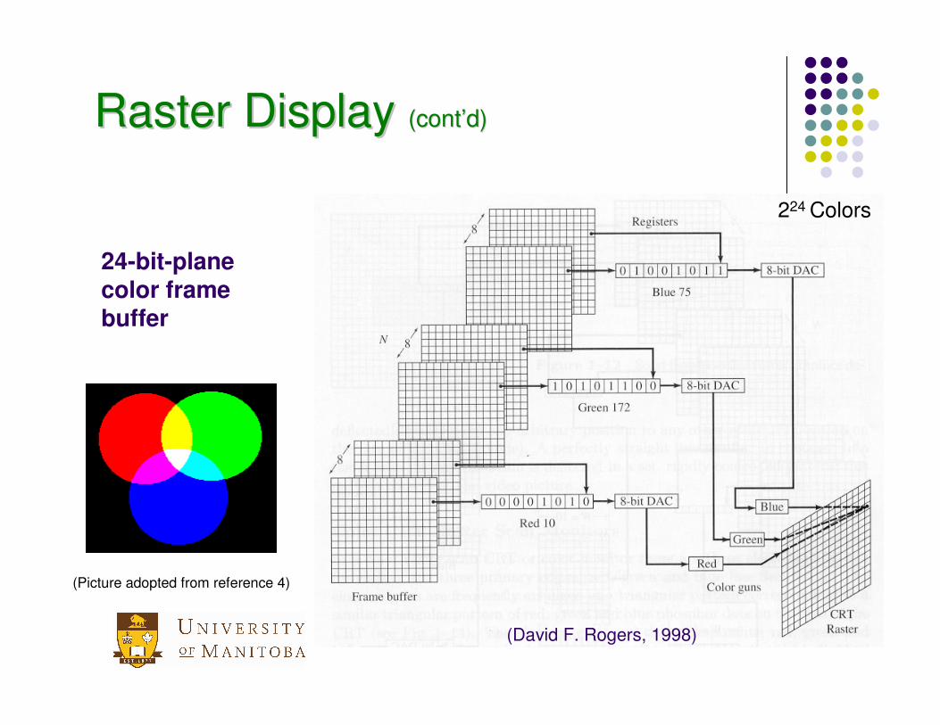
24-bit-plane color frame buffer
Raster Display Raster Display (cont(cont’’d)d)
(Picture adopted from reference 4)
224 Colors

14
Size of Frame BufferSize of Frame BufferGiven: A 24-bit-plane color frame buffer has a 1280 x 1024 vertical dot matrix. Find the least RAM size of the bitmap (refresh buffer). If the resolution is 78 pixels per inch, what is the active display area of the screen?
Solve required frame buffer1. size of frame buffer = 24 x 1280 x 1024 / 8 bits/byte = 3932160 byte
or 3.9 MB2. The active display area = 1280/78 * 1024/78 = 16.4’’ * 13.1”.

15
Comparison of Vector and Raster Devices (pros)
Vector
• Good resolution
- Straight lines
- Smooth curves
• Require limited memory and few instructionsRaster
• Fixed frame buffer size and scanning independent of picture complexity
• Can do halftones shading

16
Comparison of Vector and Raster Devices (cons)
� Vector� Slow for complex images -- flicker on CRT� Two-level color intensity thus shading difficult and
slow
� Raster� Limited resolution (Staircase (or called ‘zigzags’))
� Requiring large memory for array storage

17
Other Types of DisplayOther Types of Display� Flat CRTFlat CRT� Liquid Crystal Display (LCD)Liquid Crystal Display (LCD)� PlasmaPlasma--Panel /Panel /ElectroElectro--Luminescent Display (ELD)Luminescent Display (ELD)

18
Liquid Crystal Display (LCD)

19
Gas-Plasma/Electro-Luminescent Display (ELD)
� Light emission from gas-discharge elements arranged in a matrix.
� Works much like a fluorescent or neon light in which light at certain wavelengths is emitted by ionizing gases entrapped between cathodes and anodes with the passage of a current at high voltage.
� AC-driven panels for color TV display and DC-driven panel for computer display
� Currently electro-luminescent display technology is more widely used.

20
Comparison of CRT, LCD and ELD

21
PrinterPrinter
� DotDot--matrix printermatrix printer
� InkInk--jet printerjet printer
� Laser printerLaser printer
� Thermal transfer printerThermal transfer printer

22
Graphical Input Devices
� Keyboard� Tablet and Puck � Light Pen� Valuator� Mouse� Touch Screen� 3-D Scanning devices

23
Key Parameters for Input DevicesKey Parameters for Input Devices
ResolutionResolution: the smallest distance the device requires to recognize two adjacent points as spatially separate or addressable.
AccuracyAccuracy: the error in the measurement of actual data by the input data.
RepeatabilityRepeatability measures the device ability to return to a given position.
LinearityLinearity measures the response of a device to the user hand movements.

24
KeyboardKeyboard
� Alphanumeric characters
� ASCII (American Standard Code for Information Interchange)
A --- 1000001
a --- 1100001

25
Tablet and Puck
Tablet
Tablet Coordinates
Screen Command Bufferx1 x2
y2y1

26
TabletTablet
(Ibrahim Zied, 1991)

27
Valuators/Control DialsValuators/Control Dials
Valuators provide scalar values that are based on potentiometers. Generally this value is a real number between zero and some real maximum.
Used for activating rotation, translation, scaling or zoom function.
(adapted from reference 10)

28
Light Pen� The photomultiplier records the passage of the
electron beam. Time lapse from the start of Raster determines the pen location.
Electron Beam and Raster Scanning
Lens Computer
Photomultiplier

29
MouseMouse
measures its relative movement from its last position
The rotation of the wheel is encoded into digital values via potentiometers

30
TrackballTrackball
A trackball allows a precise fingertip control. The ball rotates freely within its mount. It was used historically in radar and flight control systems to navigate the screen display cursor.

31
Mouse and Joystick
Vx
Vy
potentiometer
roller
ball
x y
A/D Computer
Joystick

32
Touch Screen� Arrays of infrared light sources and array of
detectors are used to generate invisible light grids. A finger interrupts two light beams and provides x and y coordinates.
Light Lens
33
Scanning Devices (3-D)
� Digitizer� Scanner� Machine vision
34
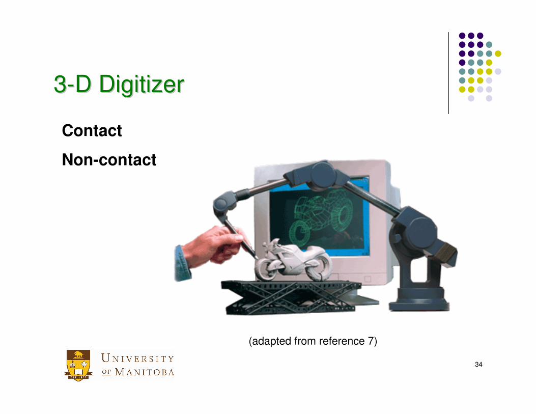
33--D DigitizerD Digitizer
(adapted from reference 7)
Contact
Non-contact

35
Data GloveData GloveThe data glove records 3D hand and finger positions as well as motions. Many pressure sensors are embedded in the glove finger joints. The sensor converts the small pressure generated by blending the finger into an electrical signal.

36
Scanner

37
Triangulation-based Scanning

38
ReferencesReferences1. http://physinfo.ulb.ac.be/cit_courseware/hs200/m4e.htm2. http://www.sceptre.com/Products/Monitors/definitions/definitions.htm#CRT3. http://www.tpub.com/content/fc/14102/css/14102_15.htm4. http://funsan.biomed.mcgill.ca/~funnell/InforMed/Bacon/Graph/graph001.html5. http://www.lexmark.com/Canada/products/index.html6. http://www.5dt.com/hardware.html#glove7. http://www.immersion.com/digitizer/8. http://www.kensington.com/html/1436.html9. http://www.wacom-europe.com/10. http://tclab.kaist.ac.kr/~syshin

39
Quick Questions� Raster devices are good for shaded images� Vector devices have poor resolution for smooth curves� LCD involves the light emission from gas-discharge elements� Touch sensors work by detecting blocked light beams by
finger, pen, etc.� An eight-plane raster display (8bits/pixel) has a 640*800 dot
matrix, what is the minimum refresh buffer size?� If one sees 10 black lines per inch on a white screen, the
resolution of the device is then 10 lines/inch along the direction.
� Today’s hardware of a CAD system needs only common and inexpensive devices.
� 3D scanners are widely used in reverse engineering.

40
Summary
� Evolution of hardware configuration for CAD systems
� Output devices � Vector devices versus raster devices � Printers� CRT, LCD, ELD
� Input devices� Scanning devices


![[CAD CAM CAE] Ansys - Userguide](https://static.fdocuments.net/doc/165x107/543e0826b1af9f1f2b8b45c7/cad-cam-cae-ansys-userguide.jpg)