Hardware Installation Manual - Bircomftp.bircom.com/AudioCodes/Mediant_800/Docs/LTRT... · 5.7...
42
Hardware Installation Manual Version 6.8 October 2014 Document # LTRT-10257 Mediant™ 800B Gateway and E-SBC SIP Protocol
Transcript of Hardware Installation Manual - Bircomftp.bircom.com/AudioCodes/Mediant_800/Docs/LTRT... · 5.7...

Hardware Installation Manual
Version 6.8 October 2014
Document # LTRT-10257
Mediant™ 800B
Gateway and E-SBC
SIP Protocol


Version 6.8 3 Mediant 800B Gateway & E-SBC
Hardware Installation Manual Contents
Table of Contents 1 Introduction ......................................................................................................... 9
2 Unpacking the Device ...................................................................................... 11
3 Physical Description ........................................................................................ 13
3.1 Physical Dimensions and Operating Environment ................................................. 13 3.2 Front Panel Description .......................................................................................... 14
3.2.1 Ports and Buttons.................................................................................................... 14 3.2.2 LEDs Description .................................................................................................... 16
3.2.2.1 LAN Interface LEDs ................................................................................. 16 3.2.2.2 FXS LEDs ................................................................................................ 16 3.2.2.3 FXO LEDs ................................................................................................ 17 3.2.2.4 BRI LEDs ................................................................................................. 17 3.2.2.5 E1/T1 LEDs ............................................................................................. 18 3.2.2.6 Operational Status LEDs ......................................................................... 18 3.2.2.7 Power LEDs ............................................................................................. 18
3.3 Rear Panel Description .......................................................................................... 19
4 Mounting the Device ........................................................................................ 21
4.1 Desktop Mounting .................................................................................................. 21 4.2 19-Inch Rack Mounting .......................................................................................... 22
4.2.1 Using a Pre-installed Rack Shelf ............................................................................ 22 4.2.2 Using Mounting Brackets ........................................................................................ 23
5 Cabling the Device ........................................................................................... 25
5.1 Grounding the Device ............................................................................................. 25 5.2 Connecting to LAN ................................................................................................. 26 5.3 Analog Devices ...................................................................................................... 28
5.3.1 Connecting the FXS Interfaces ............................................................................... 28 5.3.2 Connecting the FXO Interfaces ............................................................................... 29 5.3.3 Connecting the FXS Analog Lifeline ....................................................................... 30
5.4 ISDN BRI Interfaces ............................................................................................... 31 5.4.1 Connecting to BRI Lines ......................................................................................... 31 5.4.2 Connecting the PSTN Fallback for BRI Lines ......................................................... 32
5.5 Connecting to ISDN PRI (E1/T1) Trunks ................................................................ 33 5.6 Connecting to a Computer for Serial Communication ............................................ 34 5.7 Connecting the OSN Server ................................................................................... 36 5.8 Powering up the Device ......................................................................................... 38
6 Maintenance – Replacing the Power Fuse ..................................................... 39
A Installing CentOS Ver. 4.7 on OSN Server ...................................................... 41

Hardware Installation Manual 4 Document #: LTRT-10257
Mediant 800B Gateway & E-SBC
List of Figures Figure 3-1: Mediant 800B Front Panel................................................................................................... 14 Figure 3-2: Mediant 800 Front Panel ..................................................................................................... 14 Figure 3-3: Rear Panel .......................................................................................................................... 19 Figure 4-1: Rubber Foot Attached to Underside of Device.................................................................... 21 Figure 4-2: Mounting Bracket (Right) ..................................................................................................... 23 Figure 4-3: Attaching the Mounting Brackets ........................................................................................ 23 Figure 5-1: Grounding the Device .......................................................................................................... 25 Figure 5-2: LAN Port-Pair Groups and Web Interface String Names .................................................... 26 Figure 5-3: Connecting the LAN Ports ................................................................................................... 27 Figure 5-4: RJ-11 Connector Pinouts for FXS Interface ........................................................................ 28 Figure 5-5: Connecting FXS Interfaces ................................................................................................. 28 Figure 5-6: RJ-11 Connector Pinouts for FXO Interface ....................................................................... 29 Figure 5-7: Connecting FXO Interfaces ................................................................................................. 29 Figure 5-8: RJ-11 Connector Pinouts for FXS Lifeline .......................................................................... 30 Figure 5-9: Cabling FXS Lifeline ............................................................................................................ 30 Figure 5-10: RJ-45 Connector Pinouts for BRI Ports ............................................................................ 31 Figure 5-11: Cabling BRI Ports .............................................................................................................. 31 Figure 5-12: Cabling (Ports 1 and 2) PSTN Fallback ............................................................................ 32 Figure 5-13: RJ-48c Connector Pinouts for E1/T1 ................................................................................ 33 Figure 5-14: Cabling E1/T1 Ports .......................................................................................................... 33 Figure 5-15: Orderable RS-232 Cable Adapter ..................................................................................... 34 Figure 5-16: Cabling Serial Interface (RJ-45) on Mediant 800B ........................................................... 35 Figure 5-17: Cabling OSN Server Ports ................................................................................................ 37 Figure 5-18: Connecting to the Power Supply ....................................................................................... 38 Figure 6-1: Opening the Fuse Cavity ..................................................................................................... 39 Figure 6-2: Removed Power Fuse ......................................................................................................... 39

Version 6.8 5 Mediant 800B Gateway & E-SBC
Hardware Installation Manual Contents
List of Tables Table 3-1: Physical Dimensions and Operating Environment ............................................................... 13 Table 3-2: Front Panel Description ........................................................................................................ 14 Table 3-3: LAN LEDs Description .......................................................................................................... 16 Table 3-4: FXS LEDs Description .......................................................................................................... 16 Table 3-5: FXO LEDs Description ......................................................................................................... 17 Table 3-6: BRI LEDs Description ........................................................................................................... 17 Table 3-7: E1/T1 LEDs Description ....................................................................................................... 18 Table 3-8: STATUS LEDs Description................................................................................................... 18 Table 3-9: POWER LEDs Description ................................................................................................... 18 Table 3-10: Rear Panel Description ....................................................................................................... 19 Table 5-1: RJ-45 Connector Pinouts for GbE/FE .................................................................................. 26 Table 5-2: OSN Server Platforms .......................................................................................................... 36 Table 5-3: Power Specifications ............................................................................................................ 38 Table 6-1: Allowed Fuses for the Device ............................................................................................... 39

Hardware Installation Manual 6 Document #: LTRT-10257
Mediant 800B Gateway & E-SBC
This page is intentionally left blank.

Version 6.8 7 Mediant 800B Gateway & E-SBC
Hardware Installation Manual Notices
Notice This document describes the hardware installation for AudioCodes Mediant 800B Gateway and E-SBC. Information contained in this document is believed to be accurate and reliable at the time of printing. However, due to ongoing product improvements and revisions, AudioCodes cannot guarantee accuracy of printed material after the Date Published nor can it accept responsibility for errors or omissions. Before consulting this document, check the corresponding Release Notes regarding feature preconditions and/or specific support in this release. In cases where there are discrepancies between this document and the Release Notes, the information in the Release Notes supersedes that in this document. Updates to this document and other documents as well as software files can be downloaded by registered customers at http://www.audiocodes.com/downloads.
© Copyright 2014 AudioCodes Ltd. All rights reserved.
This document is subject to change without notice.
Date Published: October-29-2014
Trademarks AudioCodes, AC, AudioCoded, Ardito, CTI2, CTI², CTI Squared, HD VoIP, HD VoIP Sounds Better, InTouch, IPmedia, Mediant, MediaPack, NetCoder, Netrake, Nuera, Open Solutions Network, OSN, Stretto, TrunkPack, VMAS, VoicePacketizer, VoIPerfect, VoIPerfectHD, What’s Inside Matters, Your Gateway To VoIP and 3GX are trademarks or registered trademarks of AudioCodes Limited. All other products or trademarks are property of their respective owners.
WEEE EU Directive Pursuant to the WEEE EU Directive, electronic and electrical waste must not be disposed of with unsorted waste. Please contact your local recycling authority for disposal of this product.
Customer Support Customer technical support and services are provided by AudioCodes or by an authorized AudioCodes Service Partner. For more information on how to buy technical support for AudioCodes products and for contact information, please visit our Web site at www.audiocodes.com/support.
Abbreviations and Terminology Each abbreviation, unless widely used, is spelled out in full when first used. Throughout this manual, unless otherwise specified, the term device refers to Mediant 800B Gateway and E-SBC.

Hardware Installation Manual 8 Document #: LTRT-10257
Mediant 800B Gateway & E-SBC
Related Documentation
Document Name
SIP Release Notes
Mediant 800B Gateway and E-SBC User's Manual
CLI Reference Guide
Notes and Warnings
Warning: The device is an INDOOR unit and therefore, must be installed only indoors. In addition, FXS and Ethernet port interface cabling must be routed only indoors and must not exit the building.
Note: Open source software may have been added and/or amended for this product. For further information, please visit our website at http://audiocodes.com/support or contact your AudioCodes sales representative.
Caution Electrical Shock Do not open or disassemble this device. The device carries high voltage and contact with internal components may expose you to electrical shock and bodily harm.
Warning: The device must be installed and serviced only by qualified service personnel.
Warning: For deployment in Finland, Sweden and Norway, the device must be installed ONLY in restricted access locations that are compliant with ETS 300 253 guidelines where equipotential bonding has been implemented.
Warning: Disconnect the device from the mains and Telephone Network Voltage (TNV) before servicing.
Documentation Feedback AudioCodes continually strives to produce high quality documentation. If you have any comments (suggestions or errors) regarding this document, please fill out the Documentation Feedback form on our Web site at http://www.audiocodes.com/downloads. Your valuable feedback is highly appreciated.

Version 6.8 9 Mediant 800B Gateway & E-SBC
Hardware Installation Manual 1. Introduction
1 Introduction This document provides a hardware description of the Mediant 800B Gateway and E-SBC (hereafter referred to as device) and step-by-step procedures for mounting and cabling the device. The device supports the following interfaces (customer ordered): Up to 2 E1/T1 port interfaces (over single copper wire pair). Up to 8 BRI ports (supporting up to 16 voice channels). Up to 12 FXS port interfaces. Up to 12 FXO port interfaces. 12 LAN Ethernet interfaces - up to 4 Gigabit Ethernet ports and up to 8 Fast Ethernet
ports. These ports operate in port-pair redundancy, providing up to 6 port-pair groups. Open Solutions Network (OSN) server platform for hosting third-party applications
such as an IP PBX.
Notes:
• Hardware configurations may change without notice. Currently available hardware configurations are listed in AudioCodes Price Book. For available hardware configurations, contact your AudioCodes sales representative.
• For configuring the different interfaces, refer to the User's Manual.

Hardware Installation Manual 10 Document #: LTRT-10257
Mediant 800B Gateway & E-SBC
This page is intentionally left blank.

Version 6.8 11 Mediant 800B Gateway & E-SBC
Hardware Installation Manual 2. Unpacking the Device
2 Unpacking the Device Follow the procedure below for unpacking the carton in which the device is shipped.
To unpack the device: 1. Open the carton and remove packing materials. 2. Remove the chassis from the carton. 3. Check that there is no equipment damage. 4. Ensure that in addition to the chassis, the package contains the following items:
• Four anti-slide bumpers for desktop installation • Two mounting brackets for 19-inch rack mounting • One FXS Lifeline cable adapter (only for models with FXS interfaces) • One AC power cable
5. Check, retain and process any documents. If there are any damaged or missing items, notify your AudioCodes sales representative.

Hardware Installation Manual 12 Document #: LTRT-10257
Mediant 800B Gateway & E-SBC
This page is intentionally left blank.

Version 6.8 13 Mediant 800B Gateway & E-SBC
Hardware Installation Manual 3. Physical Description
3 Physical Description This section provides a physical description of the device.
Note: The Mediant 800 chassis platform has been upgraded. This revised chassis is referred to as Mediant 800B. The shipped chassis version depends on your ordered hardware configuration. For more information, contact your AudioCodes sales representative. In addition, throughout this manual, the Mediant 800B is used in illustrations, unless specific instructions are necessary for the Mediant 800 chassis. In such a case, both chassis versions are shown.
3.1 Physical Dimensions and Operating Environment The device's physical dimensions and operating environment are listed in the table below:
Table 3-1: Physical Dimensions and Operating Environment
Physical Specification Description
Dimensions (H x W x D) 1U x 32 x 34.5 cm (12.6 x 13.6 inches)
Weight 2.5 kg (5.5 lbs.)
Environmental Operational: 5 to 40°C (41 to 104°F) Storage: -25 to 85°C (-13 to 185°F) Humidity: 10 to 90% non-condensing

Hardware Installation Manual 14 Document #: LTRT-10257
Mediant 800B Gateway & E-SBC
3.2 Front Panel Description The front panel provides the telephony port interfaces, various networking ports, reset pinhole button, and LEDs.
3.2.1 Ports and Buttons The device's front panel is shown in the figure below and described in the subsequent table.
Figure 3-1: Mediant 800B Front Panel
Figure 3-2: Mediant 800 Front Panel
Note: The figures above are used only as an example. The number and type of port interfaces depends on the ordered model.
Table 3-2: Front Panel Description
Item # Label Description
1 USB/WWAN USB port, used for various functionalities such as saving debug captures to a USB storage device. The number of ports depends on chassis version: • Mediant 800B: 2 USB ports • Mediant 800: 1 USB port

Version 6.8 15 Mediant 800B Gateway & E-SBC
Hardware Installation Manual 3. Physical Description
Item # Label Description
2 RS-232 RS-232 port for serial communication. The type of port connector depends on chassis version: • Mediant 800B: RJ-45 • Mediant 800: 12-pin female LX40-12P Hirose connector
3 POWER / STATUS
LEDs indicating the status of the power and reboot/initialization. For more information, see Section 3.2.2 on page 16.
4 FXS / FXO / BRI / Digital
Telephony port interfaces that can include one or a combination of the following, depending on the ordered model: • FXS port interfaces (RJ-11) • FXO port interfaces (RJ-11) • ISDN BRI port interfaces (RJ-45) • E1/T1 port interfaces (RJ-48) Notes: • The FXS/FXO interfaces support loop-start signalling (indoor only). • For supported hardware configuration options, refer to the Release
Notes. 5 - Reset pinhole button for resetting the device and optionally, for restoring
the device factory defaults. To restore the device to factory defaults, do the following: With a paper clip or any other similar pointed object, press and hold
down the Reset pinhole button for at least 12 seconds, but no more than 25 seconds.
6 GE Up to four 10/100/1000Base-T (Gigabit Ethernet) LAN ports for connecting IP phones, computers, or switches. These ports support the following features: 1+1 LAN port redundancy: These ports are grouped in pairs, where
one port is active and the other redundant. When a failure occurs in the active port, a switchover is done to the redundant port.
Half- and full-duplex modes Auto-negotiation Straight or crossover cable detection
7 FE Eight Fast Ethernet (10/100Base-TX) RJ-45 LAN ports for connecting IP phones, computers, or switches. The supported port features are the same as the GE ports (see Item #6 above).

Hardware Installation Manual 16 Document #: LTRT-10257
Mediant 800B Gateway & E-SBC
3.2.2 LEDs Description The front panel provides various LEDs depending on the device's hardware configuration (e.g., the available telephony interfaces). These LEDs are described in the subsequent subsections.
3.2.2.1 LAN Interface LEDs Each LAN port provides a LED (located on its left) for indicating LAN operating status, as described in the table below.
Table 3-3: LAN LEDs Description
LED Color
LED State
Description
Green On Ethernet link established.
Flashing Data is being received or transmitted.
- Off No Ethernet link.
3.2.2.2 FXS LEDs Each FXS port provides a LED for indicating operating status, as described in the table below.
Table 3-4: FXS LEDs Description
LED Color
LED State
Description
Green On Phone is off-hooked.
Flashing Rings the extension line.
Red On Error - malfunction in line or out of service due to Serial Peripheral Interface (SPI) failure.
Disabled port initiated by user (using the CLI command, analog-port-enable)
- Off Phone is on hook.
- Off No power received by the device.

Version 6.8 17 Mediant 800B Gateway & E-SBC
Hardware Installation Manual 3. Physical Description
3.2.2.3 FXO LEDs Each FXO port provides a LED for indicating operating status, as described in the table below.
Table 3-5: FXO LEDs Description
LED Color
LED State
Description
Green On FXO line is off-hooked toward the PBX.
Flashing Ring signal detected from the PBX.
Red On Error - malfunction in line or out of service due to Serial Peripheral Interface (SPI) failure.
Disabled port initiated by user (using the CLI command, analog-port-enable)
- Off Line is on hook.
- Off No power received by the device.
3.2.2.4 BRI LEDs Each BRI port provides a LED for indicating operating status, as described in the table below:
Table 3-6: BRI LEDs Description
Color State Description
Green On Physical layer (Layer 1) is synchronized (normal operation).
Red On Physical layer (Layer 1) is not synchronized.
- Off Trunk is not active.

Hardware Installation Manual 18 Document #: LTRT-10257
Mediant 800B Gateway & E-SBC
3.2.2.5 E1/T1 LEDs Each trunk port provides a LED for indicating operating status, as described in the table below:
Table 3-7: E1/T1 LEDs Description
Color State Description
Green On Trunk is synchronized (normal operation).
Red On Loss due to any of the following signals: LOS - Loss of Signal LOF - Loss of Frame AIS - Alarm Indication Signal (the Blue Alarm) RAI - Remote Alarm Indication (the Yellow Alarm)
- Off Failure / disruption in the AC power supply or the power is currently not being supplied to the device through the AC power supply entry.
3.2.2.6 Operational Status LEDs The STATUS LED indicates the operating status, as described in the table below.
Table 3-8: STATUS LEDs Description
LED Color LED State Description
Green On The device is operational and in Standalone mode (not in High-Availability mode).
Flashing Initial rebooting stage.
Slow Flash HA mode - LED on Active device.
Slow-Fast Flash
HA mode - LED on Redundant device.
Red On Boot failure.
Off Advanced rebooting stage.
3.2.2.7 Power LEDs The POWER LED indicates the operating status, as described in the table below.
Table 3-9: POWER LEDs Description
LED Color
LED State
Description
Green On Power is received by the device.
- Off No power received by the device.

Version 6.8 19 Mediant 800B Gateway & E-SBC
Hardware Installation Manual 3. Physical Description
3.3 Rear Panel Description The device's rear panel is shown in the figure below and described in the subsequent table.
Figure 3-3: Rear Panel
Note: The figure above is used only as an example. The Open Network Solution (OSN) server ports are a customer ordered item and depend on the ordered OSN server platform.
Table 3-10: Rear Panel Description
Item # Label Description
1 OSN USB Three USB ports (Standard-A type) for connecting computer peripherals (e.g., mouse and keyboard). These are used when implementing the OSN. Note: These ports are available only if the device is equipped with the OSN server (customer ordered).
2 OSN VGA 15-Pin DB-type female VGA port for connecting to a monitor (screen). This port is used when implementing the OSN. Note: This port is available only if the device is equipped with the OSN server (customer ordered).
3 - Reset button for resetting the OSN server.
4 GE 1 GE 2
10/100/1000Base-T Ethernet ports (RJ-45) for connecting directly to the OSN server. For example, one port can be connected to the LAN (to IP Phones) and the second port to the WAN interface (to an IP PBX). Note: the number of ports depends on ordered OSN server platform (see Section 5.7 on page 36).
5
Protective earthing screw.
6 100-240V~1.5A 50-60Hz
3-Prong AC power supply entry.

Hardware Installation Manual 20 Document #: LTRT-10257
Mediant 800B Gateway & E-SBC
This page is intentionally left blank.

Version 6.8 21 Mediant 800B Gateway & E-SBC
Hardware Installation Manual 4. Mounting the Device
4 Mounting the Device The device can be mounted in one of the following ways: Placed on a desktop – see Section 4.1 on page 21 Installed in a standard 19-inch rack – see Section 4.2 on page 22
Warning: Do not place any equipment directly on top of the device or adjacent to its sides (at least 13-cm separation). In addition, if you are mounting the device in a 19-inch rack, ensure that at least a 3U separation is maintained between the device and other mounted devices or equipment.
4.1 Desktop Mounting The device can be placed on a desktop when its four anti-slide bumpers (supplied) are attached to the underside of the device.
To attach the anti-slide rubber bumpers to the device: 1. Flip the device over so that its underside faces up. 2. Locate the four anti-slide grooves on the underside - one in each corner. 3. Peel off the adhesive, anti-slide rubber feet and stick one in each anti-slide groove.
Figure 4-1: Rubber Foot Attached to Underside of Device
4. Flip the device over again so that it rests on the rubber feet and place it in the required
position on a desktop.

Hardware Installation Manual 22 Document #: LTRT-10257
Mediant 800B Gateway & E-SBC
4.2 19-Inch Rack Mounting The device can be installed in a standard 19-inch rack by implementing one of the following mounting methods: Placing it on a pre-installed shelf in a 19-inch rack – see Section 4.2.1 on page 22 Attaching it directly to the rack’s frame using the device's mounting brackets (supplied)
that need to be attached to the chassis – see Section 4.2.2 on page 23
Rack Mount Safety Instructions
When installing the chassis in a rack, implement the following safety instructions:
• Elevated Operating Ambient Temperature: If installed in a closed or multi-unit rack assembly, the operating ambient temperature of the rack environment may be greater than room ambient temperature. Therefore, consideration should be given to installing the equipment in an environment with maximum ambient temperature (Tma) of 40°C (104°F).
• Reduced Air Flow: Installation of the equipment in a rack should be such that the amount of air flow required for safe operation on the equipment is not compromised.
• Mechanical Loading: Mounting of the equipment in the rack should be such that a hazardous condition is not achieved due to uneven mechanical loading.
• Circuit Overloading: Consideration should be given to the connection of the equipment to the supply circuit and the effect that overloading of the circuits might have on over-current protection and supply wiring. Appropriate consideration of equipment nameplate ratings should be used when addressing this concern.
• Reliable Earthing: Reliable earthing of rack-mounted equipment should be maintained. Particular attention should be given to supply connections other than direct connections to the branch circuit (e.g., use of power strips). For earthing the device, see Section 5.1 on page 25.
4.2.1 Using a Pre-installed Rack Shelf The procedure below describes how to place the device on a pre-installed shelf in a 19-inch rack.
To mount the device on a pre-installed shelf in the rack: 1. Before installing it in the rack, ensure that you have a pre-installed rack shelf on which
the device can be placed. 2. Place the device on the pre-installed shelf in the rack.

Version 6.8 23 Mediant 800B Gateway & E-SBC
Hardware Installation Manual 4. Mounting the Device
4.2.2 Using Mounting Brackets The procedure below describes how to mount the device in a 19-inch rack. Rack mounting involves placing the device on a pre-installed rack shelf and then attaching the device's mounting brackets (to the device and rack frame). The purpose of the mounting brackets is to secure the device to the rack.
Figure 4-2: Mounting Bracket (Right)
Note: 19-inch rack mounting using mounting brackets is a customer ordered feature.
To mount the device in a 19-inch rack using mounting brackets: 1. Attach the two mounting brackets (supplied) to each side of the device's chassis, using
the supplied screws, as shown in the figure below:
Figure 4-3: Attaching the Mounting Brackets
2. Place the device on a pre-installed shelf in the rack. 3. Attach the ends of the mounting brackets (that you installed in Step 1) to the vertical
track of the rack's frame, using standard 19-inch rack bolts (not supplied).

Hardware Installation Manual 24 Document #: LTRT-10257
Mediant 800B Gateway & E-SBC
This page is intentionally left blank.
Version 6.8 25 Mediant 800B Gateway & E-SBC
Hardware Installation Manual 5. Cabling the Device
5 Cabling the Device This section describes the cabling of the device, which includes the following: Connecting to earth or ground – see Section 5.1 on page 25 Connecting to the LAN – see Section 5.2 on page 26 Connecting to FXS equipment – see Section 5.3.1 on page 28 Connecting to FXO equipment – see Section 5.3.2 on page 29 Connecting the FXS Analog Lifeline – see Section 5.3.3 on page 30 Connecting the BRI lines – see Section 5.4.1 on page 31 Connecting the PSTN Fallback for BRI lines – see Section 5.4.2 on page 32 Connecting the E1/T1 trunks – see Section 5.5 on page 33 Connecting to a PC for serial communication – see Section 5.6 on page 34 Connecting the OSN server – see Section 5.7 on page 30 Connecting to the power supply – see Section 5.8 on page 38
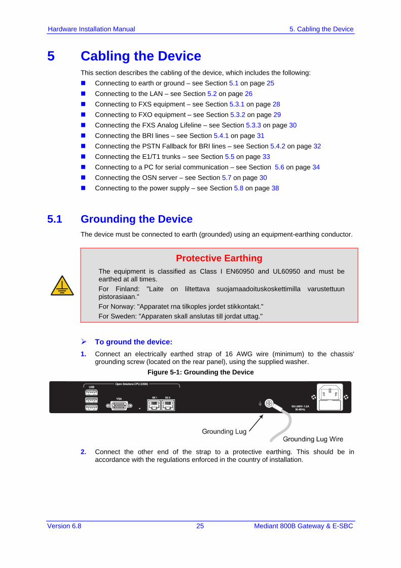
5.1 Grounding the Device The device must be connected to earth (grounded) using an equipment-earthing conductor.
Protective Earthing The equipment is classified as Class I EN60950 and UL60950 and must be earthed at all times. For Finland: "Laite on liltettava suojamaadoituskoskettimilla varustettuun pistorasiaan." For Norway: "Apparatet rna tilkoples jordet stikkontakt." For Sweden: "Apparaten skall anslutas till jordat uttag."
To ground the device: 1. Connect an electrically earthed strap of 16 AWG wire (minimum) to the chassis'
grounding screw (located on the rear panel), using the supplied washer. Figure 5-1: Grounding the Device
2. Connect the other end of the strap to a protective earthing. This should be in
accordance with the regulations enforced in the country of installation.
Hardware Installation Manual 26 Document #: LTRT-10257
Mediant 800B Gateway & E-SBC
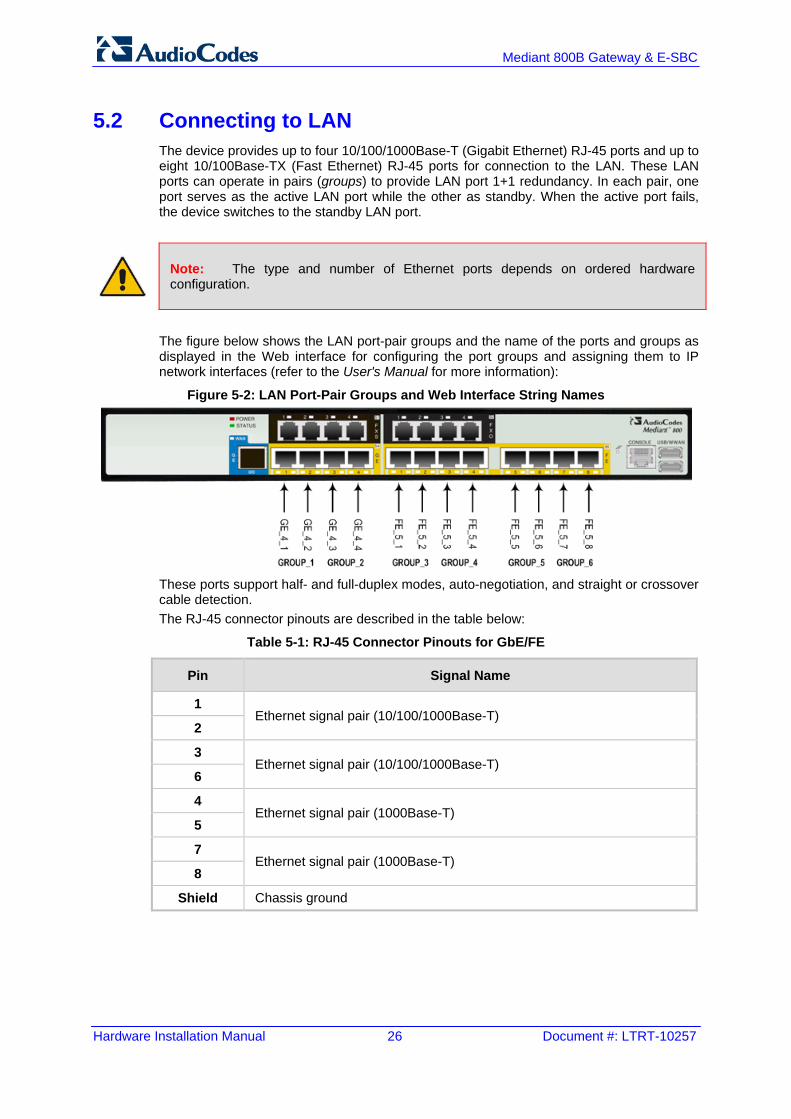
5.2 Connecting to LAN The device provides up to four 10/100/1000Base-T (Gigabit Ethernet) RJ-45 ports and up to eight 10/100Base-TX (Fast Ethernet) RJ-45 ports for connection to the LAN. These LAN ports can operate in pairs (groups) to provide LAN port 1+1 redundancy. In each pair, one port serves as the active LAN port while the other as standby. When the active port fails, the device switches to the standby LAN port.
Note: The type and number of Ethernet ports depends on ordered hardware configuration.
The figure below shows the LAN port-pair groups and the name of the ports and groups as displayed in the Web interface for configuring the port groups and assigning them to IP network interfaces (refer to the User's Manual for more information):
Figure 5-2: LAN Port-Pair Groups and Web Interface String Names
These ports support half- and full-duplex modes, auto-negotiation, and straight or crossover cable detection. The RJ-45 connector pinouts are described in the table below:
Table 5-1: RJ-45 Connector Pinouts for GbE/FE
Pin Signal Name
1 Ethernet signal pair (10/100/1000Base-T)
2
3 Ethernet signal pair (10/100/1000Base-T)
6
4 Ethernet signal pair (1000Base-T)
5
7 Ethernet signal pair (1000Base-T)
8
Shield Chassis ground

Version 6.8 27 Mediant 800B Gateway & E-SBC
Hardware Installation Manual 5. Cabling the Device
To connect the device to the LAN: 1. Connect one end of a straight-through RJ-45 Cat 5e or Cat 6 cable to the RJ-45 port
labeled GE (for Gigabit Ethernet ports) and/or FE (for Fast Ethernet ports).
Figure 5-3: Connecting the LAN Ports
2. Connect the other end of the cable to the Gigabit Ethernet network (for the GE ports)
and/or Fast Ethernet network (for the FE ports). 3. For 1+1 LAN protection, repeat steps 1 and 2 for the standby port, but connect it to
another network (in the same subnet).
Note: If you are implementing the LAN port-pair redundancy, ensure that the two ports making up a pair are each connected to a different network (in the same subnet).

Hardware Installation Manual 28 Document #: LTRT-10257
Mediant 800B Gateway & E-SBC
5.3 Analog Devices This section describes how to connect the device to analog equipment.
5.3.1 Connecting the FXS Interfaces The procedure below describes how to cable the device's FXS interfaces.
Warnings: • The device is an INDOOR unit and therefore, must be installed only indoors. • FXS port interface cabling must be routed only indoors and must not exit the building. • Make sure that the FXS ports are connected to the appropriate, external devices;
otherwise, damage to the device may occur. • FXS ports are considered TNV-2.
Notes: • FXS interfaces are a customer-ordered item. • FXS is the interface replacing the Exchange (i.e., the CO or the PBX) and connects to
analog telephones, dial-up modems, and fax machines. The FXS is designed to supply line voltage and ringing current to these telephone devices. An FXS VoIP device interfaces between the analog telephone devices and the Internet.
The RJ-11 connector pinouts used for this connection are shown in the figure below:
Figure 5-4: RJ-11 Connector Pinouts for FXS Interface
To connect the FXS interfaces: 1. Connect one end of an RJ-11 cable to the FXS port (labeled FXS).
Figure 5-5: Connecting FXS Interfaces
2. Connect the other end of the cable to the required telephone interface (e.g., fax
machine, dial-up modem, and analog POTS telephone).

Version 6.8 29 Mediant 800B Gateway & E-SBC
Hardware Installation Manual 5. Cabling the Device
5.3.2 Connecting the FXO Interfaces The procedure below describes how to cable the device's FXO interfaces.
Warnings: • To protect against electrical shock and fire, use a minimum 26-AWG wire to connect
FXO ports to the PSTN. • Ensure that the FXO ports are connected to the appropriate, external devices;
otherwise, damage to the device may occur. • FXO ports are considered TNV-3.
Notes:
• FXO interfaces are a customer-ordered item. • FXO is the interface replacing the analog telephone and connects to a Public Switched
Telephone Network (PSTN) line from the Central Office (CO) or to a Private Branch Exchange (PBX). The FXO is designed to receive line voltage and ringing current, supplied from the CO or the PBX (similar to an analog telephone). An FXO VoIP device interfaces between the CO/PBX line and the Internet.
The RJ-11 connector pinouts used for this connection are shown in the figure below:
Figure 5-6: RJ-11 Connector Pinouts for FXO Interface
To connect the FXO interfaces: 1. Connect one end of an RJ-11 cable to the FXO port (labeled FXO).
Figure 5-7: Connecting FXO Interfaces
2. Connect the other end of the cable to the required telephone interface: (e.g., telephone
exchange analog lines or PBX extensions).

Hardware Installation Manual 30 Document #: LTRT-10257
Mediant 800B Gateway & E-SBC
5.3.3 Connecting the FXS Analog Lifeline The device's analog Lifeline phone feature redirects IP calls to the PSTN upon a power outage or loss of IP network connectivity, thereby guaranteeing call continuity. The Lifeline is provided by FXS Port # 1. This port connects to the analog POTS phone and the PSTN / PBX using a splitter cable. The Lifeline splitter connects pins 1 and 4 to another source of an FXS port, and pins 2 and 3 to the POTS phone.
Notes:
• Analog Lifeline cabling is applicable only if the device is ordered with FXS interfaces. • The number of supported Lifelines depends on the device’s hardware configuration.
For the combined FXS/FXO configuration, one Lifeline is available; for the 12-FXS configuration, up to three Lifelines are available.
• The scenario upon which the Lifeline is activated is configured by the LifeLineType ini file parameter. For more information, refer to the User's Manual.
The RJ-11 connector pinouts are shown in the figure below.
Figure 5-8: RJ-11 Connector Pinouts for FXS Lifeline
To cable the FXS Lifeline: 1. Connect the Lifeline Splitter (supplied) to FXS Port 1. 2. On the Lifeline splitter cable, do the following:
a. Connect the analog telephone to Port A. b. Connect an analog PSTN line to Port B.
Figure 5-9: Cabling FXS Lifeline

Version 6.8 31 Mediant 800B Gateway & E-SBC
Hardware Installation Manual 5. Cabling the Device
5.4 ISDN BRI Interfaces This section describes how to cable the BRI interfaces.
5.4.1 Connecting to BRI Lines The device provides up to four BRI S/T ports. These ports connect to ISDN terminal equipment such as ISDN telephones. Each BRI port can be configured either as termination equipment/user side (TE) or network termination/network side (NT). Up to eight terminal equipment (TE) devices can be connected per BRI S/T port, using an ISDN S-bus that provides eight ISDN ports. When configured as NT, the BRI port drives a nominal voltage of 38 V with limited current supply of up to 100 mA.
Note: BRI interfaces are a customer-ordered item.
The connector pinouts for the BRI port when configured as TE or NT are shown below:
Figure 5-10: RJ-45 Connector Pinouts for BRI Ports
Warning: To protect against electrical shock and fire, use a 26 AWG min wire to connect the BRI ports to the PSTN.
To connect the BRI ports: 1. Connect the BRI cable to the device's BRI RJ-45 port. 2. Connect the other end of the cable to your ISDN telephone or PBX/PSTN switch.
Figure 5-11: Cabling BRI Ports

Hardware Installation Manual 32 Document #: LTRT-10257
Mediant 800B Gateway & E-SBC
5.4.2 Connecting the PSTN Fallback for BRI Lines The device supports a PSTN Fallback feature for BRI lines, whereby if a power outage or IP connectivity problem (e.g., no ping) occurs, IP calls are re-routed to the PSTN. This guarantees call continuity. PSTN Fallback is supported if the device houses one or more BRI modules, where each BRI module provides two or four spans. In the event of a PSTN fallback, the BRI module's metallic relay switch automatically connects line Port 1 (I) to Port 2 (II) of the BRI module. For example, if a PBX trunk is connected to Port 1 and the PSTN network is connected to Port 2, when PSTN Fallback is activated, calls from the PBX are routed directly to the PSTN through Port 2.
To connect the BRI line interfaces for 1+1 PSTN Fallback: 1. Connect line 1 to a PBX. 2. On the same BRI module, connect line 2 to the PSTN.
Figure 5-12: Cabling (Ports 1 and 2) PSTN Fallback
Notes:
• PSTN Fallback is supported only on BRI interfaces. • PSTN Fallback is supported only between ports on the same BRI module. • The scenarios that trigger PSTN Fallback (i.e., power outage and/or IP network loss)
are configured by the TrunkLifeLineType parameter. For more information, see the User's Manual.
• This PSTN Fallback feature has no relation to the PSTN Fallback Software Upgrade Key.
Version 6.8 33 Mediant 800B Gateway & E-SBC
Hardware Installation Manual 5. Cabling the Device
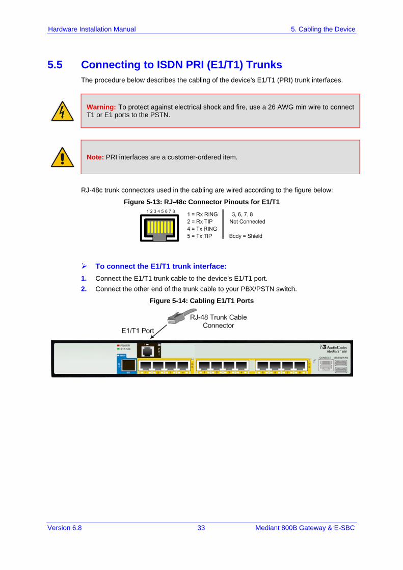
5.5 Connecting to ISDN PRI (E1/T1) Trunks The procedure below describes the cabling of the device's E1/T1 (PRI) trunk interfaces.
Warning: To protect against electrical shock and fire, use a 26 AWG min wire to connect T1 or E1 ports to the PSTN.
Note: PRI interfaces are a customer-ordered item.
RJ-48c trunk connectors used in the cabling are wired according to the figure below:
Figure 5-13: RJ-48c Connector Pinouts for E1/T1
To connect the E1/T1 trunk interface: 1. Connect the E1/T1 trunk cable to the device’s E1/T1 port. 2. Connect the other end of the trunk cable to your PBX/PSTN switch.
Figure 5-14: Cabling E1/T1 Ports

Hardware Installation Manual 34 Document #: LTRT-10257
Mediant 800B Gateway & E-SBC
5.6 Connecting to a Computer for Serial Communication The device provides an RS-232 serial interface port on its front panel for serial communication with a PC. The serial port interface connector depends on your device's hardware chassis platform: Mediant 800B:
• Port Type: RJ-45 • Cable: RJ-45 to DB-9
Mediant 800: • Port Type: 12-pin female LX40-12P Hirose connector • Cable: Can be purchased from AudioCodes - RS-232 cable adapter (9-pin DB to
flat connector). The Customer Product Number is PicoBlade-Serial. This orderable item is supplied in a kit of 10 cables. The figure below displays this cable adapter, where "P1" and "P2" are standard 9-pin DB for PC COM connectivity and "P3" is the Hirose male connector.
Figure 5-15: Orderable RS-232 Cable Adapter

Version 6.8 35 Mediant 800B Gateway & E-SBC
Hardware Installation Manual 5. Cabling the Device
To connect the device's serial interface to a computer: Mediant 800B:
a. Connect the RJ-45 cable connector to the device's serial port, labeled CONSOLE. b. Connect the other end of the cable to the COM1 or COM2 RS-232 communication
port on your PC.
Figure 5-16: Cabling Serial Interface (RJ-45) on Mediant 800B
Mediant 800 (using AudioCodes serial cable adapter - not supplied):
a. Connect one end of the crossover RS-232 cable ("P3") to the device's serial port, labeled CONSOLE.
b. Connect the red 9-pin DB connector ("P1") on the other end of the cable, to the COM1 or COM2 RS-232 communication port on your PC.

Hardware Installation Manual 36 Document #: LTRT-10257
Mediant 800B Gateway & E-SBC
5.7 Connecting the OSN Server The device may be ordered with an embedded, Open Network Solution (OSN) platform for hosting third-party services such as an IP PBX. The OSN modules are located on the device's rear panel. The available, orderable OSN server platforms are listed in the table below.
Table 5-2: OSN Server Platforms
OSN Platform
CPU Memory Storage Interfaces
OSN2 2nd Generation Intel Core Celeron 1.6 GHz
2 or 4 GB HDD 500 GB Two external Gigabit Ethernet Internal Gigabit Ethernet Three USB 2.0 via Connection
Module VGA
OSN4 3rd Generation Intel Core i7 Quad Core
16 GB ECC DDR3
HDD (500 GB) or SSD (240 GB)
Two external Gigabit Ethernet Internal Gigabit Ethernet Three USB 2.0 via Connection
Module VGA
OSN5 Intel Atom N2800 1.86 GHz Dual Core
2G HDD 500 GB External Gigabit Ethernet Internal Gigabit Ethernet Three USB 2.0 via Connection
Module VGA
Notes:
• The OSN server platform is a customer ordered feature and thus, the OSN interface ports, located on the rear panel are available only when the device is purchased with the OSN server.
• The OSN server also provides an internal interface connection to the Mediant 800B LAN switch. In other words, instead of using the Gigabit Ethernet port on the rear panel, you can use the LAN port #1 located on the front panel for connecting to the OSN server.
• If your device is shipped with an OSN server, you can download the latest OSN drivers from AudioCodes Web site at http://www.audiocodes.com/downloads.
• The table above lists the currently available OSN platforms. This list may change without notice. To check for any updated information on available OSN platforms, contact your AudioCodes sales representative.

Version 6.8 37 Mediant 800B Gateway & E-SBC
Hardware Installation Manual 5. Cabling the Device
To connect to the OSN server: 1. Perform the following cabling procedures on the OSN server, located on the rear
panel: a. Connect computer peripherals (e.g., mouse and keyboard) to the USB ports
(Standard-A type) labeled USB. b. Connect the USB storage device containing the operating system installation files
(Linux or Microsoft Windows) to one of the USB ports, labeled USB. c. Connect a monitor using a 15-Pin D-type male connector to the VGA female port,
labeled VGA. d. Connect to the network using an RJ-45 Ethernet cable connector to the Gigabit
Ethernet port/s (labeled GE 1 and GE 2).
Figure 5-17: Cabling OSN Server Ports
2. Connect the device to power. 3. Follow the operating system's installation instructions to install the operating system.
To reset the OSN server: Insert a sharp-pointed object (such as a drawing pin) into the Reset pinhole and then
extract it after a second; the OSN server performs a reset.

Hardware Installation Manual 38 Document #: LTRT-10257
Mediant 800B Gateway & E-SBC
5.8 Powering up the Device The device receives power from a standard alternating current (AC) electrical outlet. The connection is made using the supplied AC power cord.
Table 5-3: Power Specifications
Physical Specification Value
Input Voltage Single universal AC power supply 100 to 240V
AC Input Frequency 50 to 60 Hz
AC Input Current 1.5A
Warnings:
• The device must be connected to a socket-outlet providing a protective earthing connection.
• Use only the AC power cord that is supplied with the device. • For replacing the power fuse, see Section 6 on page 39.
To connect the device to the power supply: 1. Connect the line socket of the AC power cord (supplied) to the device's AC power
socket (labeled 100-240V 1.5A ~50-60 Hz), located on the rear panel.
Figure 5-18: Connecting to the Power Supply
2. Connect the plug at the other end of the AC power cord to a standard electrical outlet. Once you have cabled and powered-up the device, the POWER LED on the front panel lights up green. For a description of this LED, see Section 3.2.2.7 on page 18.

Version 6.8 39 Mediant 800B Gateway & E-SBC
Hardware Installation Manual 6. Maintenance – Replacing the Power Fuse
6 Maintenance – Replacing the Power Fuse The device contains a fuse that protects the device from excessive current. The fuse is located on the rear panel, below the power socket. To replace the fuse, use only one of the following fuses described in the table below:
Table 6-1: Allowed Fuses for the Device
Manufacturer Manufacturer Part Number
BEL 5ET2.5-R
CONQUER UDL 2.50
LITTEFUSE 021302.5MXP
Caution For continuous protection, replace only with the same fuse type and rating fuse.
To replace the fuse: 1. Unplug the power cord from the electrical outlet. 2. Using a small flathead screwdriver, gently pries open the fuse cavity as illustrated in
the figure below:
Figure 6-1: Opening the Fuse Cavity
3. Carefully remove the fuse from the fuse cavity.
Figure 6-2: Removed Power Fuse
4. Insert the new fuse securely into the fuse cavity until you hear a click sound. 5. Reconnect the power cord and verify that the Power LED is lit green.

Hardware Installation Manual 40 Document #: LTRT-10257
Mediant 800B Gateway & E-SBC
This page is intentionally left blank.

Version 6.8 41 Mediant 800B Gateway & E-SBC
Hardware Installation Manual A. Installing CentOS Ver. 4.7 on OSN Server
A Installing CentOS Ver. 4.7 on OSN Server This appendix provides important information for installing CentOS Ver. 4.7 Linux Distribution on the OSN server: When installing CentOS, ensure that you type linux irqpoll at the boot: prompt. For CentOS to identify the OSN server’s Gigabit Ethernet (GE) interfaces, do the
following: 1. Obtain the following files from AudioCodes:
♦ Binary compiled CentOS 4.7 driver for Intel e1000e Ethernet controller on Mediant 800B Gateway and SBC (e1000e.ko)
♦ Manual pages (e1000e.7.gz) 2. Copy the files to the /root directory. 3. Remove any old e1000e modules (if any) and install the new module and manual
pages: #> find /lib/modules/2.6.9-78.ELsmp –name e1000e.ko –exec rm –rf {}\; #> find /lib/modules/2.6.9-78.ELsmp –name e1000e.ko.gz –exec rm –rf {}\; #> install –D –m 644 /root/e1000e.ko /lib/modules/2.6.9-78.ELsmp/kernel/drivers/net/e1000e/e1000e.ko #> /sbin/depmod –a #> echo “alias eth1 e1000e” >> /etc/modprobe.conf #> echo “alias eth2 e1000e” >> /etc/modprobe.conf #> install –D –m 644 /root/e1000e.7.gz /usr/share/man/man7/e1000e.7.gz #> man –c –P`cat > /dev/null` e1000e #> modprobe e1000e
Note: The character #> depicts the CLI prompt and is not part of the command. 4. Restart networking, by running the following command:
#> service network restart
Note: The character #> depicts the CLI prompt (i.e., this is not part of the command). The final result should be as follows: Eth0 = r8169 (INTERNAL and not in use ) Eth1 = e1000e (GE LAN) Eth2 = e1000e (GE LAN)

Hardware Installation Manual
www.audiocodes.com