Hardware Description - FCC ID can obtain the RRU frequency band and power supply information from...
37
RRU3952(850M) Hardware Description Issue Draft A Date 2014-12-31 HUAWEI TECHNOLOGIES CO., LTD.
Transcript of Hardware Description - FCC ID can obtain the RRU frequency band and power supply information from...

RRU3952(850M)
Hardware Description
Issue Draft A
Date 2014-12-31
HUAWEI TECHNOLOGIES CO., LTD.

Copyright © Huawei Technologies Co., Ltd. 2014. All rights reserved.
No part of this document may be reproduced or transmitted in any form or by any means without prior writtenconsent of Huawei Technologies Co., Ltd. Trademarks and Permissions
and other Huawei trademarks are trademarks of Huawei Technologies Co., Ltd.All other trademarks and trade names mentioned in this document are the property of their respective holders. NoticeThe purchased products, services and features are stipulated by the contract made between Huawei and thecustomer. All or part of the products, services and features described in this document may not be within thepurchase scope or the usage scope. Unless otherwise specified in the contract, all statements, information,and recommendations in this document are provided "AS IS" without warranties, guarantees or representationsof any kind, either express or implied.
The information in this document is subject to change without notice. Every effort has been made in thepreparation of this document to ensure accuracy of the contents, but all statements, information, andrecommendations in this document do not constitute a warranty of any kind, express or implied.
Huawei Technologies Co., Ltd.Address: Huawei Industrial Base
Bantian, LonggangShenzhen 518129People's Republic of China
Website: http://www.huawei.com
Email: [email protected]
Issue Draft A (2014-12-31) Huawei Proprietary and ConfidentialCopyright © Huawei Technologies Co., Ltd.
i
About This Document
PurposeThis document provides reference for planning and deploying an RRU3952(850M) (referred toas RRU in this document). It presents the exterior and describes the ports, functions, cable types,connector specifications, and cable connections of the RRU.
Product VersionsThe following table lists the product versions related to the RRU3952(850M).
Product Name Solution Version Product Version
DBS3900 l SRAN8.0 and laterversions
l GBSS15.0 and laterversions
l RAN15.0 and laterversions
l eRAN6.0 and laterversions
V100R008C00 and laterversions
Intended AudienceThis document is intended for:
l Base station installation engineersl System engineersl Site maintenance engineers
Organization1 Changes in RRU3952(850M) Hardware Description
RRU3952(850M)Hardware Description About This Document
Issue Draft A (2014-12-31) Huawei Proprietary and ConfidentialCopyright © Huawei Technologies Co., Ltd.
ii

This section describes the changes in RRU3952(850M) Hardware Description.
2 RRU Introduction
This chapter describes the exterior and function of the RRU as well as the ports and indicatorson the RRU.
3 RRU Cables
This chapter describes RRU cables.
4 RF Cable Connections for the RRU3952(850M)
RF cable connections for the RRU vary depending on the configurations of the RRU and antenna.
5 RRU Auxiliary Devices
This chapter describes RRU auxiliary devices.
ConventionsSymbol Conventions
The symbols that may be found in this document are defined as follows.
Symbol Description
Indicates an imminently hazardous situation which, if notavoided, will result in death or serious injury.
Indicates a potentially hazardous situation which, if notavoided, could result in death or serious injury.
Indicates a potentially hazardous situation which, if notavoided, may result in minor or moderate injury.
Indicates a potentially hazardous situation which, if notavoided, could result in equipment damage, data loss,performance deterioration, or unanticipated results.NOTICE is used to address practices not related to personalinjury.
Calls attention to important information, best practices andtips.NOTE is used to address information not related to personalinjury, equipment damage, and environment deterioration.
General Conventions
The general conventions that may be found in this document are defined as follows.
RRU3952(850M)Hardware Description About This Document
Issue Draft A (2014-12-31) Huawei Proprietary and ConfidentialCopyright © Huawei Technologies Co., Ltd.
iii

Convention Description
Times New Roman Normal paragraphs are in Times New Roman.
Boldface Names of files, directories, folders, and users are inboldface. For example, log in as user root.
Italic Book titles are in italics.
Courier New Examples of information displayed on the screen are inCourier New.
Command Conventions
The command conventions that may be found in this document are defined as follows.
Convention Description
Boldface The keywords of a command line are in boldface.
Italic Command arguments are in italics.
[ ] Items (keywords or arguments) in brackets [ ] are optional.
{ x | y | ... } Optional items are grouped in braces and separated byvertical bars. One item is selected.
[ x | y | ... ] Optional items are grouped in brackets and separated byvertical bars. One item is selected or no item is selected.
{ x | y | ... }* Optional items are grouped in braces and separated byvertical bars. A minimum of one item or a maximum of allitems can be selected.
[ x | y | ... ]* Optional items are grouped in brackets and separated byvertical bars. Several items or no item can be selected.
GUI Conventions
The GUI conventions that may be found in this document are defined as follows.
Convention Description
Boldface Buttons, menus, parameters, tabs, window, and dialog titlesare in boldface. For example, click OK.
> Multi-level menus are in boldface and separated by the ">"signs. For example, choose File > Create > Folder.
Keyboard Operations
RRU3952(850M)Hardware Description About This Document
Issue Draft A (2014-12-31) Huawei Proprietary and ConfidentialCopyright © Huawei Technologies Co., Ltd.
iv

The keyboard operations that may be found in this document are defined as follows.
Format Description
Key Press the key. For example, press Enter and press Tab.
Key 1+Key 2 Press the keys concurrently. For example, pressing Ctrl+Alt+A means the three keys should be pressed concurrently.
Key 1, Key 2 Press the keys in turn. For example, pressing Alt, A meansthe two keys should be pressed in turn.
Mouse Operations
The mouse operations that may be found in this document are defined as follows.
Action Description
Click Select and release the primary mouse button without movingthe pointer.
Double-click Press the primary mouse button twice continuously andquickly without moving the pointer.
Drag Press and hold the primary mouse button and move thepointer to a certain position.
RRU3952(850M)Hardware Description About This Document
Issue Draft A (2014-12-31) Huawei Proprietary and ConfidentialCopyright © Huawei Technologies Co., Ltd.
v

Contents
About This Document.....................................................................................................................ii
1 Changes in RRU3952(850M) Hardware Description..............................................................1
2 RRU Introduction..........................................................................................................................22.1 RRU Exterior..................................................................................................................................................................32.2 RRU Functions...............................................................................................................................................................42.3 RRU Technical Specifications........................................................................................................................................52.4 RRU Ports.......................................................................................................................................................................52.5 RRU Indicators...............................................................................................................................................................72.6 Optical Modules.............................................................................................................................................................9
3 RRU Cables...................................................................................................................................113.1 RRU Cables..................................................................................................................................................................133.2 RRU PGND Cable........................................................................................................................................................143.3 RRU Power Cable........................................................................................................................................................153.4 RRU Alarm Cable........................................................................................................................................................163.5 CPRI Fiber Optic Cable................................................................................................................................................173.6 RRU RF Jumper...........................................................................................................................................................213.7 RRU AISG Multi-Wire Cable......................................................................................................................................213.8 RRU AISG Extension Cable........................................................................................................................................233.9 Inter-RRU RF Cable.....................................................................................................................................................24
4 RF Cable Connections for the RRU3952(850M).....................................................................25
5 RRU Auxiliary Devices..............................................................................................................275.1 IFS06............................................................................................................................................................................285.2 OCB..............................................................................................................................................................................29
RRU3952(850M)Hardware Description Contents
Issue Draft A (2014-12-31) Huawei Proprietary and ConfidentialCopyright © Huawei Technologies Co., Ltd.
vi

1 Changes in RRU3952(850M) HardwareDescription
This section describes the changes in RRU3952(850M) Hardware Description.
Draft A (2014-12-31)This is a draft.
RRU3952(850M)Hardware Description 1 Changes in RRU3952(850M) Hardware Description
Issue Draft A (2014-12-31) Huawei Proprietary and ConfidentialCopyright © Huawei Technologies Co., Ltd.
1

2 RRU Introduction
About This Chapter
This chapter describes the exterior and function of the RRU as well as the ports and indicatorson the RRU.
2.1 RRU ExteriorThis section describes the exterior and dimensions of an RRU.
2.2 RRU FunctionsThis section describes main functions of an RRU.
2.3 RRU Technical SpecificationsThis section describes technical specifications of an RRU, including supported modes, frequencybands, RF specifications, engineering specifications, and antenna capabilities.
2.4 RRU PortsThis section describes ports on the RRU panels. An RRU has a bottom panel, cabling cavitypanel, and indicator panel.
2.5 RRU IndicatorsThis section describes six indicators on an RRU. They indicate the running status of the RRU.
2.6 Optical ModulesAn optical module transmits optical signals between an optical port and an optical fiber.
RRU3952(850M)Hardware Description 2 RRU Introduction
Issue Draft A (2014-12-31) Huawei Proprietary and ConfidentialCopyright © Huawei Technologies Co., Ltd.
2

2.1 RRU ExteriorThis section describes the exterior and dimensions of an RRU.
Figure 2-1 shows the exterior of an RRU.
Figure 2-1 RRU exterior
Figure 2-2 shows RRU dimensions.
Figure 2-2 RRU dimensions
You can obtain the RRU frequency band and power supply information from the configurationlabel on the cover plate and obtain the RRU name from the nameplate on the side of RRU thataccommodates the conversion bracket. Figure 2-3 shows the positions of the configuration labeland nameplate on the RRU.
RRU3952(850M)Hardware Description 2 RRU Introduction
Issue Draft A (2014-12-31) Huawei Proprietary and ConfidentialCopyright © Huawei Technologies Co., Ltd.
3

NOTE
The actual label and nameplate may differ from what is shown in the figure.
Figure 2-3 Positions of the label and nameplate
(1) Configuration label (2) Nameplate (3) Frequency band
(4) Power supply module (5) Module name -
2.2 RRU FunctionsThis section describes main functions of an RRU.
The Remote Radio Unit (RRU) consists of the high-speed interface unit, signal processing unit,power amplifier, duplexer, extension ports, and power module.
Figure 2-4 shows the functional structure of the RRU.
Figure 2-4 Functional structure of an RRU
RRU3952(850M)Hardware Description 2 RRU Introduction
Issue Draft A (2014-12-31) Huawei Proprietary and ConfidentialCopyright © Huawei Technologies Co., Ltd.
4

NOTE
For details about the extension ports, see 2.4 RRU Ports.
The RRU performs the following functions:
l Receives downlink baseband data from the BBU and sends uplink baseband data to theBBU.
l Receives RF signals from the antenna system, down-converts the signals to intermediatefrequency (IF) signals, amplifies the IF signals, performs analog-to-digital conversion, andup-converts RF signals to the transmit (TX) band.
l Multiplexes receive (RX) and TX signals on the RF channel so that these signals can sharethe same antenna channel, and filters the RX and TX signals.
l Provides a built-in Bias Tee (BT). Besides receiving and transmiting RF signals, RRU RFports A and B transmit coupled RF signals and OOK signals to antennas through the built-in BT. The RF ports A, B, C, and D also supply DC power to the tower mounted amplifier(TMA).
l The RRU can be powered by the AC/DC power module. In this case, this RRU is calledAC RRU. For details about the AC/DC power module, see AC/DC Power Module UserGuide or OPM15M User Guide.
2.3 RRU Technical SpecificationsThis section describes technical specifications of an RRU, including supported modes, frequencybands, RF specifications, engineering specifications, and antenna capabilities.
For details about technical specifications of an RRU, see section Technical Specifications ofRRUs in the 3900 Series Base Station Technical Description.
2.4 RRU PortsThis section describes ports on the RRU panels. An RRU has a bottom panel, cabling cavitypanel, and indicator panel.
Figure 2-5 shows the ports on the RRU panels.
RRU3952(850M)Hardware Description 2 RRU Introduction
Issue Draft A (2014-12-31) Huawei Proprietary and ConfidentialCopyright © Huawei Technologies Co., Ltd.
5
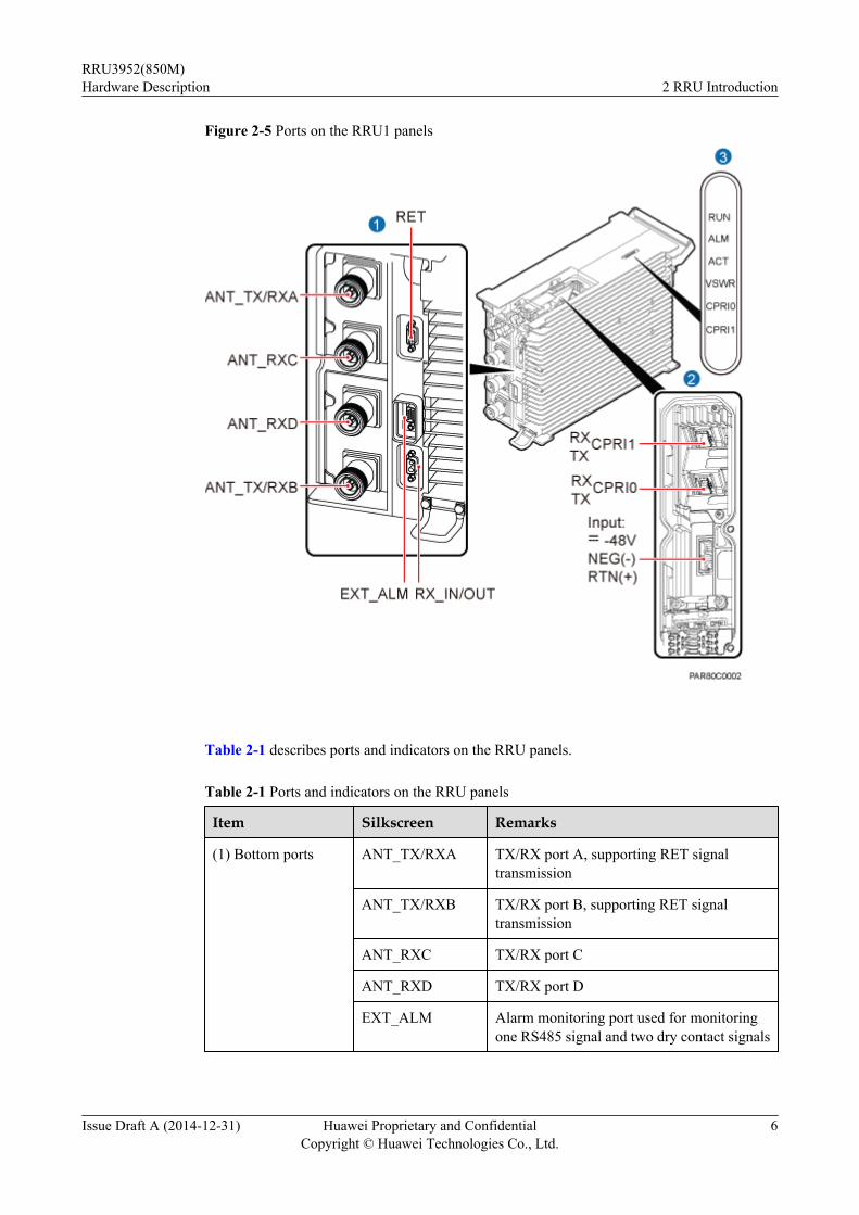
Figure 2-5 Ports on the RRU1 panels
Table 2-1 describes ports and indicators on the RRU panels.
Table 2-1 Ports and indicators on the RRU panels
Item Silkscreen Remarks
(1) Bottom ports ANT_TX/RXA TX/RX port A, supporting RET signaltransmission
ANT_TX/RXB TX/RX port B, supporting RET signaltransmission
ANT_RXC TX/RX port C
ANT_RXD TX/RX port D
EXT_ALM Alarm monitoring port used for monitoringone RS485 signal and two dry contact signals
RRU3952(850M)Hardware Description 2 RRU Introduction
Issue Draft A (2014-12-31) Huawei Proprietary and ConfidentialCopyright © Huawei Technologies Co., Ltd.
6

Item Silkscreen Remarks
RET Communication port for the RET antenna,supporting RET signal transmission
RX_IN/OUT Interconnection port
(2) Ports in the cablingcavity
RTN(+) Power supply socket, for details about RRUpower cable experience and specifications,see 3.3 RRU Power Cable.NEG(-)
CPRI0 Optical/electrical port 0, connected to theBBU
CPRI1 Optical/electrical port 1, connected to theBBU
(3) Indicator RUN For details, see 2.5 RRU Indicators.
ALM
ACT
VSWR
CPRI0
CPRI1
NOTE
l The port for transmitting RET signals is determined by the software.
l Connect the CPRI0 port to the BBU by default in the single-mode scenario.
2.5 RRU IndicatorsThis section describes six indicators on an RRU. They indicate the running status of the RRU.
For detailed positions of RRU indicators, see 2.4 RRU Ports.
Table 2-2 describes RRU indicators.
Table 2-2 RRU Indicators
Indicator Color Status Meaning
RUN Green Steady on The power input is available, but the board isfaulty.
Steady off No power input is available or the board isfaulty.
RRU3952(850M)Hardware Description 2 RRU Introduction
Issue Draft A (2014-12-31) Huawei Proprietary and ConfidentialCopyright © Huawei Technologies Co., Ltd.
7

Indicator Color Status Meaning
Blinking (on for1s and off for 1s)
The board is running properly.
Blinking (on for0.125s and off for0.125s)
The board software is being loaded or theboard is not working.
ALM Red Steady on Alarms are generated, and the module mustbe replaced.
Blinking (on for1s and off for 1s)
Alarms are generated. The alarms may becaused by faults on the related board or ports.Therefore, you need to locate the fault beforedeciding whether to replace the module.
Steady off No alarms are generated.
ACT Green Steady on The board is working properly when TXchannels are enabled or software is beingloaded to a board that is not started.
Blinking (on for1s and off for 1s)
The board is running with TX channelsdisabled.
VSWR Red Steady off No voltage standing wave ratio (VSWR)alarm is generated.
Blinking (on for1s and off for 1s)
VSWR alarms are generated on theANT_TX/RXB port.
Steady on VSWR alarms are generated on theANT_TX/RXA port.
Blinking (on for0.125s and off for0.125s)
VSWR alarms are generated on theANT_TX/RXA and ANT_TX/RXB ports.
CPRI0 Red andgreen
Steady green The CPRI link is running properly.
Steady red An optical module fails to receive or transmitsignals possibly because the optical moduleis faulty or the optical fiber is broken.
Blinking red (onfor 1s and off for1s)
The CPRI link is out of lock because of faultson the mutual lock of dual-mode clocksources or mismatched data rates on CPRIports.
Steady off The optical module cannot be detected or ispowered off.
CPRI1 Red andgreen
Steady green The CPRI link is running properly.
RRU3952(850M)Hardware Description 2 RRU Introduction
Issue Draft A (2014-12-31) Huawei Proprietary and ConfidentialCopyright © Huawei Technologies Co., Ltd.
8

Indicator Color Status Meaning
Steady red An optical module fails to receive or transmitsignals possibly because the optical moduleis faulty or the optical fiber is broken.
Blinking red (onfor 1s and off for1s)
The CPRI link is out of lock because of faultson the mutual lock of dual-mode clocksources or mismatched data rates on CPRIports.
Steady off The optical module cannot be detected or ispowered off.
2.6 Optical ModulesAn optical module transmits optical signals between an optical port and an optical fiber.
NOTE
The exterior and labels for an optical module in this document are for reference only.
ExteriorThe following figure shows the exterior of an optical module.
Figure 2-6 Exterior of an optical module
Optical Module LabelA label is available on each optical module, which provides information such as rate,wavelength, and transmission mode, as shown in the following figure.
RRU3952(850M)Hardware Description 2 RRU Introduction
Issue Draft A (2014-12-31) Huawei Proprietary and ConfidentialCopyright © Huawei Technologies Co., Ltd.
9

Figure 2-7 Optical module label
(1) Rate (2) Wavelength (3) Transmission mode
Optical Module TypeOptical modules can be classified into single-mode and multimode optical modules, which canbe distinguished as follows:
l The extraction lever of a single-mode optical module is blue and that of a multimode opticalmodule is black or gray.
l The transmission mode is displayed as "SM" on the label of a single-mode optical moduleand "MM" on the label of a multimode optical module.
RRU3952(850M)Hardware Description 2 RRU Introduction
Issue Draft A (2014-12-31) Huawei Proprietary and ConfidentialCopyright © Huawei Technologies Co., Ltd.
10
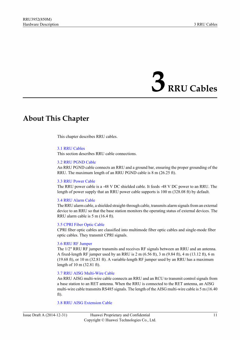
3 RRU Cables
About This Chapter
This chapter describes RRU cables.
3.1 RRU CablesThis section describes RRU cable connections.
3.2 RRU PGND CableAn RRU PGND cable connects an RRU and a ground bar, ensuring the proper grounding of theRRU. The maximum length of an RRU PGND cable is 8 m (26.25 ft).
3.3 RRU Power CableThe RRU power cable is a -48 V DC shielded cable. It feeds -48 V DC power to an RRU. Thelength of power supply that an RRU power cable supports is 100 m (328.08 ft) by default.
3.4 RRU Alarm CableThe RRU alarm cable, a shielded straight-through cable, transmits alarm signals from an externaldevice to an RRU so that the base station monitors the operating status of external devices. TheRRU alarm cable is 5 m (16.4 ft).
3.5 CPRI Fiber Optic CableCPRI fiber optic cables are classified into multimode fiber optic cables and single-mode fiberoptic cables. They transmit CPRI signals.
3.6 RRU RF JumperThe 1/2" RRU RF jumper transmits and receives RF signals between an RRU and an antenna.A fixed-length RF jumper used by an RRU is 2 m (6.56 ft), 3 m (9.84 ft), 4 m (13.12 ft), 6 m(19.68 ft), or 10 m (32.81 ft). A variable-length RF jumper used by an RRU has a maximumlength of 10 m (32.81 ft).
3.7 RRU AISG Multi-Wire CableAn RRU AISG multi-wire cable connects an RRU and an RCU to transmit control signals froma base station to an RET antenna. When the RRU is connected to the RET antenna, an AISGmulti-wire cable transmits RS485 signals. The length of the AISG multi-wire cable is 5 m (16.40ft).
3.8 RRU AISG Extension Cable
RRU3952(850M)Hardware Description 3 RRU Cables
Issue Draft A (2014-12-31) Huawei Proprietary and ConfidentialCopyright © Huawei Technologies Co., Ltd.
11

When the distance between an RRU and an RCU is longer than 5 m (16.4 ft), an AISG multi-wire cable is not long enough to connect the RRU and the RCU. In this case, an AISG extensioncable is used to extend the AISG multi-wire cable for transmitting RS485 signals. The length ofthe AISG extension cable is 15 m (49.21 ft).
3.9 Inter-RRU RF CableAn inter-RRU RF cable connects the RX_IN/OUT ports on two RRUs in the same cell andtransmits RF signals between the RRUs. The length of the inter-RRU RF cable is 2 m (6.56 ft).
RRU3952(850M)Hardware Description 3 RRU Cables
Issue Draft A (2014-12-31) Huawei Proprietary and ConfidentialCopyright © Huawei Technologies Co., Ltd.
12

3.1 RRU CablesThis section describes RRU cable connections.
Table 3-1 lists RRU cables.
Table 3-1 RRU cables
Cable One End The Other End
Connector InstallationPosition
Connector InstallationPosition
3.2 RRU PGNDCable
OT terminal(M6, 16 mm2 or0.025 in.2)
Groundterminal onthe RRU
OT terminal(M8, 16 mm2 or0.025 in.2)
Ground terminalon the groundbar
3.3 RRU PowerCable
Tool-lessfemaleconnector(pressfit type)
NEG(-) andRTN(+) portson the RRU
Depending onthe powersupplyequipment
External powerequipment
3.4 RRU AlarmCable
DB15 maleconnector
EXT_ALMport on theRRU
Cord endterminal
External alarmdevice
3.5 CPRI FiberOptic Cable(RRU working inmultimodescenarios)
DLC connector CPRI0 port onthe RRUCPRI1 port onthe RRU
DLC connector CPRI port on aboard in theBBU
3.5 CPRI FiberOptic Cable(RRU working insingle-modescenarios)
DLC connector CPRI0 port onthe RRU
DLC connector CPRI port on aboard in theBBU
3.6 RRU RFJumper
DIN maleconnector
RF ports onthe RRU
DIN maleconnector
Antenna system
3.7 RRU AISGMulti-WireCable
DB9 waterproofmale connector
RET port onthe RRU
Standard AISGfemaleconnector
Standard AISGmale connectoron the RCU oron the AISGextension cable
RRU3952(850M)Hardware Description 3 RRU Cables
Issue Draft A (2014-12-31) Huawei Proprietary and ConfidentialCopyright © Huawei Technologies Co., Ltd.
13

Cable One End The Other End
Connector InstallationPosition
Connector InstallationPosition
3.8 RRU AISGExtension Cable
Standard AISGmale connector
StandardAISG femaleconnector onthe AISGmulti-wirecable
Standard AISGfemaleconnector
Standard AISGmale connectoron the RCU
3.9 Inter-RRURF Cable
DB2W2connector
RX_IN/OUTport on theRRU
DB2W2connector
RX_IN/OUTport on the RRU
3.2 RRU PGND CableAn RRU PGND cable connects an RRU and a ground bar, ensuring the proper grounding of theRRU. The maximum length of an RRU PGND cable is 8 m (26.25 ft).
ExteriorA PGND cable is green or green and yellow with a cross-sectional area of 16 mm2 (0.025 in.2).An OT terminal is installed at each end of the cable. Figure 3-1 shows a PGND cable.
Figure 3-1 PGND cable
(1) OT terminal (M6, 16 mm2 or 0.025 in.2) (2) OT terminal (M8, 16 mm2 or 0.025 in.2)
NOTE
l If the customer prepares the PGND cable, a copper-core cable with a cross-sectional area of 16 mm2
(0.025 in.2) or larger is recommended.l One OT terminal must be added to each end of the PGND cable onsite.l You can determine the color of the cable and whether to use corresponding two-hole OT terminals
based on local regulations.
Figure 3-2 shows a two-hole OT terminal.
Figure 3-2 Two-hole OT terminal
RRU3952(850M)Hardware Description 3 RRU Cables
Issue Draft A (2014-12-31) Huawei Proprietary and ConfidentialCopyright © Huawei Technologies Co., Ltd.
14

3.3 RRU Power CableThe RRU power cable is a -48 V DC shielded cable. It feeds -48 V DC power to an RRU. Thelength of power supply that an RRU power cable supports is 100 m (328.08 ft) by default.
NOTE
l The maximum length of power supply that an RRU power cable supports is 150 m (492.12 ft). ContactHuawei engineers when an RRU power cable greater than 50 m (164.04 ft) is required.
l If a power device provided by the customer is used, the recommended specification of the circuit breakeron this power device is 15 A to 30 A.
Exterior
There are two types of RRU power cables in terms of cross-sectional areas: 5.3 mm2 (0.008 in.2) (10 AWG) complying with North American standards and 6 mm2 (0.009 in.2) complying withEuropean standards.
A tool-less female connector (pressfit type) needs to be added to one end of the RRU powercable and a corresponding terminal needs to be added to the other end based on the requirementsof the connector on the external power device, as shown in Figure 3-3.
Figure 3-3 RRU power cable
(1) -48 V DC power cable (2) Shield layer (3) Tool-less female connector(pressfit type)
Table 3-2 lists the specifications of an RRU power cable.
Table 3-2 Specifications of an RRU power cable
Cable Wire Wire Color in MostRegions
Wire Color in Other Regions
NorthAmericanStandard
EuropeanStandard
UK
RRUpowercable
RTN(+) Black Brown Blue
NEG(-) Blue Blue Gray
RRU3952(850M)Hardware Description 3 RRU Cables
Issue Draft A (2014-12-31) Huawei Proprietary and ConfidentialCopyright © Huawei Technologies Co., Ltd.
15

3.4 RRU Alarm CableThe RRU alarm cable, a shielded straight-through cable, transmits alarm signals from an externaldevice to an RRU so that the base station monitors the operating status of external devices. TheRRU alarm cable is 5 m (16.4 ft).
Exterior
An alarm cable has a DB15 waterproof male connector at one end and eight cord end terminalsat the other end, as shown in Figure 3-4.
Figure 3-4 Alarm cable
(1) DB15 waterproof male connector (2) Cord end terminal
Pin Assignment
Table 3-3 describes the pin assignment for the wires of an RRU alarm cable.
Table 3-3 Pin assignment for the wires of an RRU alarm cable
RRUAlarmPort
Pin of theWaterproofedDB15MaleConnector
Color Type Cord EndTerminal
Description
Drycontact
X1.2 White andblue
Twistedpair
X2 SWITCH_INPUT0+
X1.3 Blue X3 SWITCH_INPUT0-(GND)
X1.6 White andorange
Twistedpair
X4 SWITCH_INPUT1+
RRU3952(850M)Hardware Description 3 RRU Cables
Issue Draft A (2014-12-31) Huawei Proprietary and ConfidentialCopyright © Huawei Technologies Co., Ltd.
16

RRUAlarmPort
Pin of theWaterproofedDB15MaleConnector
Color Type Cord EndTerminal
Description
X1.7 Orange X5 SWITCH_INPUT1-(GND)
RS485 X1.10 White andgreen
Twistedpair
X6 APM RX-
X1.11 Green X7 APM RX+
X1.13 White andbrown
Twistedpair
X8 APM TX-
X1.14 Brown X9 APM TX+
3.5 CPRI Fiber Optic CableCPRI fiber optic cables are classified into multimode fiber optic cables and single-mode fiberoptic cables. They transmit CPRI signals.
Multimode fiber optic cables connect the BBU and RRU or interconnect two RRUs. Themaximum length of the multimode fiber optic cable between the BBU and RRU is 150 m (492.12ft) and the multimode fiber optic cable between two RRUs has a fixed length of 10 m (32.81 ft).
A single-mode fiber optic cable consists of the single-mode pigtail and trunk single-mode fiberoptic cable, and the single-mode pigtail and trunk single-mode fiber optic cable areinterconnected using the ODF. The maximum length of the single-mode pigtail is 20 m (65.62ft) on BBU side and 70 m (229.66 ft) on RRU side.
NOTE
l The ODF and trunk single-mode fiber optic cable are provided by the customer and must comply withthe ITU-T G.652 standard.
l The ODF is an outdoor transfer box for fiber optic cables, which interconnects the single-mode pigtailand trunk single-mode fiber optic cable.
l A multimode fiber optic cable and a single-mode fiber optic cable are connected to a multimode opticalmodule and a single-mode optical module, respectively.
ExteriorMultimode fiber optic cable: The multimode fiber optic cable has a DLC connector at each end,as shown in Figure 3-5.
RRU3952(850M)Hardware Description 3 RRU Cables
Issue Draft A (2014-12-31) Huawei Proprietary and ConfidentialCopyright © Huawei Technologies Co., Ltd.
17

Figure 3-5 Multimode fiber optic cable
(1) DLC connector (2) Breakout cable (3) Label on the breakout cable
NOTE
l When a multimode fiber optic cable connects a BBU and an RRU, the breakout cable on the BBU sideis 0.34 m (1.12 ft) and the breakout cable on the RRU side is 0.03 m (0.098 ft).
l When a multimode fiber optic cable connects two RRUs, the breakout cable on both sides is 0.03 m(0.098 ft).
Figure 3-6 shows the connection of the multimode fiber optic cable between a BBU and anRRU.
Figure 3-6 Connection of the multimode fiber optic cable between a BBU and an RRU
(1) Multimode fiber optic cable between a BBU and an RRU
Single-mode pigtail: The single-mode pigtail has a DLC connector at one end and an FC, LC,or SC connector at the other end, as shown in Figure 3-7.
RRU3952(850M)Hardware Description 3 RRU Cables
Issue Draft A (2014-12-31) Huawei Proprietary and ConfidentialCopyright © Huawei Technologies Co., Ltd.
18

Figure 3-7 Single-mode pigtail
(1) DLC connector (2) Breakoutcable
(3) Label on thebreakout cable
(4) FC connector (5) LC connector (6) SC connector
NOTE
l When a single-mode pigtail connects a BBU and an ODF, the breakout cables on the BBU side andODF side are 0.34 m (1.12 ft) and 0.8 m (2.62 ft), respectively.
l When a single-mode pigtail connects an RRU and an ODF, the breakout cables on the RRU side andODF side are 0.03 m (0.098 ft) and 0.8 m (2.62 ft), respectively.
Figure 3-8 shows the connection of the single-mode pigtail.
Figure 3-8 Connection of the single-mode pigtail
(1) Single-mode pigtail between a BBU and an ODF (2) Single-mode pigtail between an RRU and an ODF
RRU3952(850M)Hardware Description 3 RRU Cables
Issue Draft A (2014-12-31) Huawei Proprietary and ConfidentialCopyright © Huawei Technologies Co., Ltd.
19
Selection Principles
The following table describes the principles for selecting CPRI fiber optic cables.
Table 3-4 Principles for selecting CPRI fiber optic cables
RemoteDistance
Selection Principle Remarks
Less than orequal to 100 m(328.08 ft)
Multimode fiber optic cable Connects the BBU and RRUWhen it connects two RRUs, the distancebetween the two RRUs must be equal to orless than 10 m (32.81 ft).
Greater than100 m (328.08ft) and equal toor less than150 m (492.12ft)
Multimode fiber optic cable Connects the BBU and RRU
Recommended: single-modefiber optic cable (single-modepigtail and trunk single-modefiber optic cable)
The single-mode pigtail at the RRU or BBUside is connected to the trunk single-modefiber optic cable using the ODF.
Greater than150 m (492.12ft)
Single-mode fiber optic cable(single-mode pigtail and trunksingle-mode fiber optic cable)
Pin Assignment
Table 3-5 describes the labels on and recommended connections for the breakout cables of aCPRI fiber optic cable.
Table 3-5 Labels on and recommended connections for the breakout cables of a CPRI fiber opticcable
Label Installation Position
Multimode FiberOptic CableBetween a BBUand an RRU
Multimode FiberOptic CableBetween TwoRRUs
Single-Mode Pigtail
1A CPRI RX port on theRRU
CPRI RX port onRRU 1
RX port on the BBU orCPRI RX port on theRRU
1B CPRI TX port on theRRU
CPRI TX port onRRU 1
TX port on the BBU orCPRI TX port on theRRU
2A TX port on the BBU CPRI TX port onRRU 0
ODF
RRU3952(850M)Hardware Description 3 RRU Cables
Issue Draft A (2014-12-31) Huawei Proprietary and ConfidentialCopyright © Huawei Technologies Co., Ltd.
20

Label Installation Position
Multimode FiberOptic CableBetween a BBUand an RRU
Multimode FiberOptic CableBetween TwoRRUs
Single-Mode Pigtail
2B RX port on the BBU CPRI RX port onRRU 0
ODF
3.6 RRU RF JumperThe 1/2" RRU RF jumper transmits and receives RF signals between an RRU and an antenna.A fixed-length RF jumper used by an RRU is 2 m (6.56 ft), 3 m (9.84 ft), 4 m (13.12 ft), 6 m(19.68 ft), or 10 m (32.81 ft). A variable-length RF jumper used by an RRU has a maximumlength of 10 m (32.81 ft).
NOTE
l When the distance between an RRU and an antenna is less than 10 m (32.81 ft), one end of the RF jumperis connected to the ANT-TX/RXA or ANT-TX/RXB port at the bottom of the RRU, and the other end isconnected to the antenna.
l When the distance between an RRU and an antenna is greater than 10 m (32.81 ft), one end of the RF jumperis connected to a feeder, and the other end is connected to the antenna.
l If the customer prepares the RF jumper, the length of the RF jumper should be as short as possible and notexceed 2 m (6.56 ft.).
ExteriorAn RF jumper has a DIN male connector at one end and a customized connector at the otherend.
Figure 3-9 shows an RF jumper with a DIN male connector at each end.
Figure 3-9 RF jumper
(1) DIN male connector
3.7 RRU AISG Multi-Wire CableAn RRU AISG multi-wire cable connects an RRU and an RCU to transmit control signals froma base station to an RET antenna. When the RRU is connected to the RET antenna, an AISG
RRU3952(850M)Hardware Description 3 RRU Cables
Issue Draft A (2014-12-31) Huawei Proprietary and ConfidentialCopyright © Huawei Technologies Co., Ltd.
21

multi-wire cable transmits RS485 signals. The length of the AISG multi-wire cable is 5 m (16.40ft).
NOTE
An RCU is a driving motor used for the phase shifter in the RET antenna. It receives control commands from abase station and runs the commands to drive the stepper motor. Using a gear, the stepper motor drives theadjustable phase shifter in the antenna and changes the downtilt angle.
Exterior
An AISG multi-wire cable has a waterproofed DB9 male connector at one end and a standardAISG female connector at the other end, as shown in Figure 3-10.
Figure 3-10 AISG multi-wire cable
(1) Waterproofed DB9 male connector (2) Standard AISG female connector
Pin Assignment
Table 3-6 describes the pin assignment for the wires of an AISG multi-wire cable.
Table 3-6 Pin assignment for the wires of an AISG multi-wire cable
X1 End (Pin of theWaterproofedDB9 MaleConnector)
X2 End (Pin of theStandard AISGFemale Connector)
Color Type Description
X1.1 X2.1
White andblue Twisted
pair +12 V
Blue
X1.3 X2.3 White andorange Twisted
pair
RS485 B
X1.5 X2.5 Orange RS485 A
X1.4 X2.4 White andgreen
- GND
X1.9 and X1.4 areinterconnected.
- - - GND
RRU3952(850M)Hardware Description 3 RRU Cables
Issue Draft A (2014-12-31) Huawei Proprietary and ConfidentialCopyright © Huawei Technologies Co., Ltd.
22

X1 End (Pin of theWaterproofedDB9 MaleConnector)
X2 End (Pin of theStandard AISGFemale Connector)
Color Type Description
- X2.1 and X2.6 areinterconnected.
- - +12 V
- X2.4 and X2.7 areinterconnected.
- - GND
3.8 RRU AISG Extension CableWhen the distance between an RRU and an RCU is longer than 5 m (16.4 ft), an AISG multi-wire cable is not long enough to connect the RRU and the RCU. In this case, an AISG extensioncable is used to extend the AISG multi-wire cable for transmitting RS485 signals. The length ofthe AISG extension cable is 15 m (49.21 ft).
ExteriorAn AISG multi-wire cable has a standard AISG male connector at one end and a standard AISGfemale connector at the other end, as shown in Figure 3-11.
Figure 3-11 AISG extension cable
(1) Standard AISG male connector (2) Standard AISG female connector
Pin AssignmentTable 3-7 describes the pin assignment for the wires of an AISG extension cable.
RRU3952(850M)Hardware Description 3 RRU Cables
Issue Draft A (2014-12-31) Huawei Proprietary and ConfidentialCopyright © Huawei Technologies Co., Ltd.
23

Table 3-7 Pin assignment for the wires of an AISG extension cable
X1 End (Pinof theStandardAISG MaleConnector)
X2 End (Pinof theStandardAISGFemaleConnector)
Color Type Description
X1.1 X2.1 White and blue Twisted pair +12 V
Blue
X1.7 X2.7 White and orange Twisted pair DC Return
Orange
X1.3 X2.3 White and green Twisted pair RS485 B
X1.5 X2.5 Green RS485 A
X1.6 X2.6 White and brown Twisted pair +24 V
Brown
3.9 Inter-RRU RF CableAn inter-RRU RF cable connects the RX_IN/OUT ports on two RRUs in the same cell andtransmits RF signals between the RRUs. The length of the inter-RRU RF cable is 2 m (6.56 ft).
ExteriorFigure 3-12 shows an inter-RRU RF cable with a DB2W2 connector at each end.
Figure 3-12 Inter-RRU RF cable
(1) DB2W2 connector
RRU3952(850M)Hardware Description 3 RRU Cables
Issue Draft A (2014-12-31) Huawei Proprietary and ConfidentialCopyright © Huawei Technologies Co., Ltd.
24

4 RF Cable Connections for the RRU3952(850M)
RF cable connections for the RRU vary depending on the configurations of the RRU and antenna.
Description of RF Cable ConnectionsThis section describes the RF cable connections for the RRU serving a single sector. Thefollowing table lists the RF cable connections for the RRU.
Table 4-1 RF cable connections for the RRU
RRU Model Specifications of aSingle RRU
Scenario Illustration ofCableConnections
RRU3952(850M) For details, see section"Typical PowerConfiguration for RRUModules" in chapter"ConfigurationReference" in 3900Series Base StationInitial ConfigurationGuide.
2T2R See illustration 1 inFigure 4-1.
1T2R+1T2R See illustration 2 inFigure 4-1.
2T4R See illustration 3 inFigure 4-1.
RRU3952(850M)Hardware Description 4 RF Cable Connections for the RRU3952(850M)
Issue Draft A (2014-12-31) Huawei Proprietary and ConfidentialCopyright © Huawei Technologies Co., Ltd.
25

Illustration of Cable Connections
Figure 4-1 RF cable connections for the RRU
RRU3952(850M)Hardware Description 4 RF Cable Connections for the RRU3952(850M)
Issue Draft A (2014-12-31) Huawei Proprietary and ConfidentialCopyright © Huawei Technologies Co., Ltd.
26

5 RRU Auxiliary Devices
About This Chapter
This chapter describes RRU auxiliary devices.
5.1 IFS06An Indoor Floor installation Support (IFS06) is used for installing indoor RRUs.
5.2 OCBAn Outdoor Cable Conversion Box (OCB) interconnects cables of different core diameters.Power cables shipped with RRUs cannot support long-distance power supply. Therefore, whenpower supply is far from the equipment, cables with large core diameters are used, and an OCBconnects these cables and RRU power cables.
RRU3952(850M)Hardware Description 5 RRU Auxiliary Devices
Issue Draft A (2014-12-31) Huawei Proprietary and ConfidentialCopyright © Huawei Technologies Co., Ltd.
27

5.1 IFS06An Indoor Floor installation Support (IFS06) is used for installing indoor RRUs.
ExteriorFigure 5-1 shows an IFS06.
Figure 5-1 IFS06
(1) Cable tray (2) Ground bar 2 (3) Rear foot (4) Front foot
(5) Adjustable beam (6) Ground bar 1 (7) Main frame -
Functionl It can be installed on the ground.l The upper and lower adjustable beams on an IFS06 can be moved up and down to fit for
heights of RRUs.l RRUs can be installed on an IFS06 only when the ambient temperature is higher than or
equal to the lowest working temperature of the RRU and at least 5°C (41°F) lower than thehighest working temperature of the RRU. In this scenario, the IFS06 supports at least threeRRUs. When the ambient temperature is higher than or equal to the lowest working
RRU3952(850M)Hardware Description 5 RRU Auxiliary Devices
Issue Draft A (2014-12-31) Huawei Proprietary and ConfidentialCopyright © Huawei Technologies Co., Ltd.
28

temperature of the RRU and at least 10°C (50°F) lower than the highest workingtemperature of the RRU, the IFS06 supports a maximum of six RRUs.
NOTE
For details about the operating temperature of the RRU, see section "Technical Specifications ofRRUs" in 3900 Series Base Station Technical Description.
SpecificationsTable 5-1 describes IFS06 specifications.
Table 5-1 IFS06 specifications
Item Specification
Dimensions (H x W x D) 1730 mm (79 in.) x 600 mm (23.62 in.) x 600 mm (23.62 in.)
Weight 45 kg (99.23 lb)
5.2 OCBAn Outdoor Cable Conversion Box (OCB) interconnects cables of different core diameters.Power cables shipped with RRUs cannot support long-distance power supply. Therefore, whenpower supply is far from the equipment, cables with large core diameters are used, and an OCBconnects these cables and RRU power cables.
Application Scenario of an OCBFigure 5-2 shows the application scenario of an OCB.
Figure 5-2 Application scenario of an OCB
RRU3952(850M)Hardware Description 5 RRU Auxiliary Devices
Issue Draft A (2014-12-31) Huawei Proprietary and ConfidentialCopyright © Huawei Technologies Co., Ltd.
29

For details about the structure, functions, installation, and maintenance of an OCB, see the OCBUser Guide or OCB–01M User Guide.
RRU3952(850M)Hardware Description 5 RRU Auxiliary Devices
Issue Draft A (2014-12-31) Huawei Proprietary and ConfidentialCopyright © Huawei Technologies Co., Ltd.
30


![Design Considerations for 5G Base Stations to Reduce 5G ... · RRU. Let us now focus on the BBU. ... ZTE BBU and even ALCATEL LUCENT BBU [8] [9]. The following picture is given as](https://static.fdocuments.net/doc/165x107/5b4ae5d97f8b9ada3a8c8a81/design-considerations-for-5g-base-stations-to-reduce-5g-rru-let-us-now.jpg)