Handheld Laser Particle Counter - EMLab P&K Technology Handheld...3 Product Overview Carefully...
30
AIRY TECHNOLOGY INC 1 Handheld Laser Particle Counter Model: P611 Operation Manual Ver.1.0 00:00 Stopped CNT AUTO 01/01 01:00 01:00 00/01 00000 UNIT MODE LOC. SAMP INT CYC REC 12:00 51.3% Size ∑ △ START 0.3 0.5 1.0 3.0 5.0 10.0 0 0 0 0 0 0 0 0 0 0 0 0 27.2℃ MENU
Transcript of Handheld Laser Particle Counter - EMLab P&K Technology Handheld...3 Product Overview Carefully...

AIRY TECHNOLOGY INC
1
Handheld Laser Particle Counter Model: P611
Operation Manual Ver.1.0
00:00
Stopped
CNT
AUTO
01/01
01:00
01:00
00/01
00000
UNIT
MODE
LOC.
SAMP
INT
CYC
REC
12:00 51.3%
Size ∑ △
START
Set Date
00 :00:00
ENTER
0.3
0.5
1.0
3.0
5.0
10.0
0 0
0
0
0
0
0 0
0
0 0
0
27.2℃
MENU
Set Date
00 :00:00
ENTER

2
Table of Contents WARRANTY 1
SAFETY INFORMATION 2
PRODUCT OVERVIEW 3
GETTING STARTED 4
INLET NOZZLE 4
ZERO FILTER 4
AC POWER, USB PORT, AND USB CABLE 5
BATTERY 5
OPERATION 6
KEY PAD 6
POWER ON/OFF 6
SPLASH SCREEN 7
DEFAULT SCREEN 8
MAIN MENU 9
SAMPLE PROCEDURE 12
DATA HANDLING 20
SOFTWARE INSTALLATION 20
DOWNLOADING DATA 21
CALIBRATION 27
INSTRUCTIONS ON CHARGING INTERNAL BATTERY 27
APPENDIX A 28
SPECIFICATIONS 28

1
Warranty AIRY TECHNOLOGY INC warrants to the original user that this instrument shall be free from defects in material and workmanship for two years from the date of shipment.
Airy's obligations under this warranty, and the sole remedy for its breach, are limited to repair or, in Airy's sole discretion, replacement of the instrument or any of its parts. Should it become necessary to return the instrument for repair during or beyond the warranty period, user shall contact Airy Technology, Inc. (USA). E-mail: [email protected]. User is responsible for shipping charges, freight, insurance and proper packaging to prevent damage in transit.
This warranty shall be void in the event of user actions including misuse, improper wiring, operation outside of specification, improper maintenance or repair, unauthorized modification, or any other defect caused by the user's neglect or accident.
This warranty is the sole and exclusive warranty for this instrument, and no other warranty, whether written or oral, is expressed or implied. Airy specifically disclaims any implied warranties of merchantability or fitness for a specific purpose and will not be liable for any direct, indirect, incidental, consequential, or punitive damages. Airy’s total liability is limited to repair or replacement of the product.

2
Safety Information This section gives instructions for promoting safe and proper handling of the Particle Counter.
Laser Safety The Handheld Laser Particle Counter is a Class I laser- based instrument. During normal operation, you will not be exposed to laser radiation. Precautions should be taken to avoid exposure to hazardous radiation in the form of intense,
focused, invisible light. Exposure to this light may cause blindness.
Take these precautions: DO NOT remove any parts from the particle counter unless you are specifically told to do so in this
manual. DO NOT remove the housing or covers. There are no user serviceable components inside the
housing.
DANGER
The use of controls, adjustments, or procedures other than those specified in this manual may result in exposure to hazardous optical radiation.
Precautions for power use AC Adaptor The AC adapter accommodates voltage of AC 100~240V and frequency of 50/60Hz. Batteries Use four AA batteries.
DANGER
Driving voltage should be kept within specified range. Failure to follow this instruction may cause electric
shock and instrument damage.
CAUTION
Do not start sampling when the instrument is connected to a personal computer. Failure to follow this instruction may cause the instrument to work abnormally.
WARNING
PROHIBITION
WARNING
3
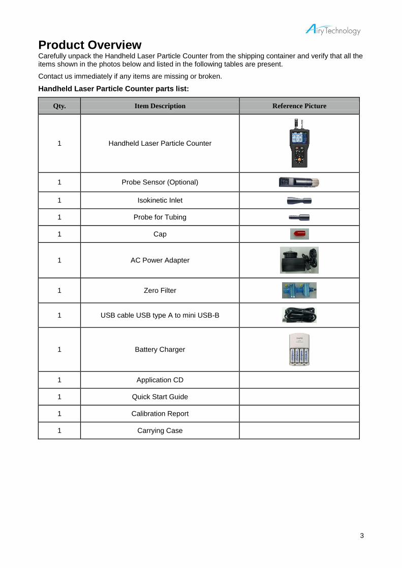
Product Overview Carefully unpack the Handheld Laser Particle Counter from the shipping container and verify that all the items shown in the photos below and listed in the following tables are present.
Contact us immediately if any items are missing or broken.
Handheld Laser Particle Counter parts list:
Qty. Item Description Reference Picture
1 Handheld Laser Particle Counter
1 Probe Sensor (Optional)
1 Isokinetic Inlet
1 Probe for Tubing
1 Cap
1 AC Power Adapter
1 Zero Filter
1 USB cable USB type A to mini USB-B
1 Battery Charger
1 Application CD
1 Quick Start Guide
1 Calibration Report
1 Carrying Case

4
Getting Started The Handheld Laser Particle Counter Model P611 is a lightweight, handheld particle counter with a TFT LCD display. It operates on battery or AC power. This model has a 0.1 CFM (2.83 L/min) flow rate and displays 6 channels simultaneously. Up to 10,000 data sets can be stored and downloaded for analysis and reported using the utility included with the device.
Inlet Nozzle User can replace the inlet nozzle between the isokinetic inlet and the tubing probe. The isokinetic inlet is used for ambient air sampling. To use the isokinetic inlet, detach the red cap from the inlet nozzle and attach the isokinetic probe. After all the samples are taken, detach the isokinetic inlet and put the red cap back before placing the unit into the carrying case. If you are planning to use a tube for sampling, please contact Airy Technology or your local distributor.
Zero Filter The zero filter cleans the sensor after your sampling at contaminated places. The zero filter also checks whether the particle counter is counting electrical noises. To use the zero filter:
1. Detach the isokinetic inlet from the main unit 2. Connect the zero filter to the main unit with the tube (Located in the plastic bag containing the zero
filter) 3. Start sampling 4. Wait until the counter is not detecting any particles 5. Stop sampling and detach the zero filter If the counter keeps on detecting particles after 1 minute of sampling, please contact Airy Technology or your local distributor.
00:00
Stopped
CNT
AUTO
01/01
01:00
01:00
00/01
00000
UNIT
MODE
LOC.
SAMP
INT
CYC
REC
12:00 51.3%
Size ∑ △
START
Set Date
00 :00:00
ENTER
0.3
0.5
1.0
3.0
5.0
10.0
0 0
0
0
0
0
0 0
0
0 0
0
27.2℃
MENU
Set Date
00 :00:00
ENTER
Probe Sensor (Option)
LCD Display
Key Pad
Inlet Nozzle
USB Port

5
AC power, USB port, and USB cable
AC Power When applying AC power, the affiliated AC adapter must also be used, as shown below. Connect Mini USB-B plug to the instrument.
Data Communication When using the USB cable to transfer data records to a PC, set it up as follows: Connect Mini USB-B plug to the instrument. Connect USB type A plug to a type A receptacle PC.
Battery The batteries have to be loaded before use and four AA Ni-MH or alkaline batteries are required. If you are using Ni-MH batteries, please charge fully before using.
Mini USB-B
USB type A
Battery Cover

6
Operation Key Pad The instrument is controlled by the key pad and its functions are shown as follows:
KEY FUNCTION
POWER Power On/Off
START/STOP Start or stop sampling
UNIT ℃/℉
DISPLAY Switch displays
BRIGHTNESS Regulate backlight
UP/DOWN/LEFT/RIGHT Move the cursor or change the values
OK Execute
Use the UP and DOWN keys to highlight a menu or a menu option. Use the LEFT and RIGHT keys to enter the sub item or leave the sub item. Use the UP and DOWN keys to perform operations such as increasing a value. Use the LEFT and RIGHT keys to move to left and right.
Power on/off Press the POWER key to turn on the instrument. Press the POWER key for more than one second, the message “Power off…” will show on the bottom of the screen. Hold it for more than two seconds to turn off the instrument.
POWER
UNIT BRIGHT
START/STOP
UP
LEFT
DOWN
RIGHT
OK DISPLAY

7
Splash Screen After the instrument is turned on, a splash screen will appear for three seconds, displaying the company logo, model number, serial number, and firmware version number (see below).
When the instrument is turned on for the first time, a clock setting screen will show up.
Set Date
00 :00:00
ENTER
Handheld Laser Particle Counter
Model : P611
Version : 1.00(00.00.00.00)
Serial Number : 0000000-00
Set Date
20 00 /01/01
ENTER
Splash Screen
Date setting screen
Clock setting screen
8
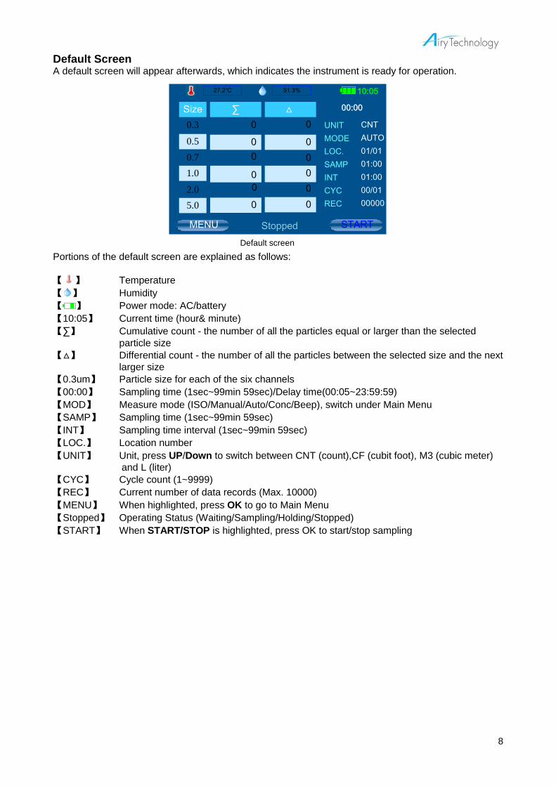
Default Screen A default screen will appear afterwards, which indicates the instrument is ready for operation.
Portions of the default screen are explained as follows:
【 】 Temperature
【 】 Humidity
【 】 Power mode: AC/battery
【10:05】 Current time (hour& minute)
【∑】 Cumulative count - the number of all the particles equal or larger than the selected
particle size
【△】 Differential count - the number of all the particles between the selected size and the next
larger size
【0.3um】 Particle size for each of the six channels
【00:00】 Sampling time (1sec~99min 59sec)/Delay time(00:05~23:59:59)
【MOD】 Measure mode (ISO/Manual/Auto/Conc/Beep), switch under Main Menu
【SAMP】 Sampling time (1sec~99min 59sec)
【INT】 Sampling time interval (1sec~99min 59sec)
【LOC.】 Location number
【UNIT】 Unit, press UP/Down to switch between CNT (count),CF (cubit foot), M3 (cubic meter)
and L (liter)
【CYC】 Cycle count (1~9999)
【REC】 Current number of data records (Max. 10000)
【MENU】 When highlighted, press OK to go to Main Menu
【Stopped】 Operating Status (Waiting/Sampling/Holding/Stopped)
【START】 When START/STOP is highlighted, press OK to start/stop sampling
00:00
Stopped
CNT
AUTO
01/01
01:00
01:00
00/01
00000
UNIT
MODE
LOC.
SAMP
INT
CYC
REC
10:05 51.3%
Size ∑ △
START
Set Date
00 :00:00
ENTER
MENU
Set Date
00 :00:00
ENTER
0.3
0.5
0.7
1.0
2.0
5.0
0 0
0
0
0
0
0 0
0
0 0
0
27.2℃
Default screen

9
Main Menu Use the UP/DOWN key to navigate between items, the OK/RIGHT key to enter a sub-item and the LEFT key to return to upper directory. Accessable Submenus from the Main Menu:
Submenu Description
sample Set measuring mode, select location, sample time, interval time, cycle count and particle unit
data Select between showing and transmitting data records
system Turn on/off sensors, set display brightness, clock and security options
user Set alarm, key sound, battery and delay time
Each of the submenus is described in the following parts of this chapter.
Sample Settings
Use the UP/DOWN key to navigate between items, the OK/RIGHT key to enter a sub-item. Use UP/DOWN/LEFT/RIGHT key to set or select and press OK to complete setting and exit. Press LEFT key to return to upper directory. The table below describes the submenu's options and available parameters.
Item Description
MODE
Auto, Manual, ISO, GMP, Beep, Conc (Concentration) * Auto mode: Sample/Interval/Cycle settings will be applied * Manual mode: Press FINISH to stop sampling. Sample/Interval/Cycle settings will not be applied * ISO mode: Sample/Interval/Cycle settings will be applied
* GMP mode: Sample/Interval/Cycle settings will be applied * Beep mode: Beep when the number of particles reaches the limit. * Conc (concentration) mode: Update result every 6 seconds
LOCATION Range 0~999
SAMPLE Range 1sec ~ 99 min 59 sec (No larger than interval time)
INTERVAL Range 1sec ~ 99 min 59 sec (No smaller than sample time)
CYCLE Range 1~9999 times
UNIT CNT (count), /cf (cubit foot), /m3 (cubic meter), /L (liter)
MODE
SAMPLE MENU
Auto
LOCATION
SAMPLE
INTERVAL
CYCLE
UNIT
001
01:00
01:00
0001
CNT
sample
data
system
user
Sample menu screen

10
Data Settings On the data process screen, sample data are stored in the instrument. They can also be transmitted to computer with a USB cable.
Show Data Record Press the OK key to enter the secondary screen where records can be referred to by the index number.
When “Show Data Record” is selected and the data mode is ISO, the sampling result will be displayed.
For example: When data # 00001 is selected, the display will show as follows (In this example, the total number of samples is 4):
/ 00004
SHOW DATA RECORD
1
data
sample
system
user
0000
Mode : ISO
Start 2011/06/18
11:01:00
Press ·UNIT· to return
SHOW DATA RECORD
DATA PROCESSING
TRANSMIT RECORD
data
sample
system
user
ISO 00001/00004 Unit:/M3
Press ·UNIT· to return
Size Cumul Diff Envi
0.3 1.278E+08 1.045E+08 26.5 ℃
0.5 23293592 21323030 50.6 %
1.0 1970562 1790457
2.5 180105 88287
3.0 91818 91818
10.0 0 0
LOCATION: 1 / 4 CYCLE: 1 / 1 SAMPLE: 01:00 INTERVAL: 01:00 START: 2011 / 07 / 18 01:46:28
Data processing
Data processing

11
Use the UP/LEFT and DOWN/RIGHT keys to scroll through the records, UNIT to go back to the select record screen. In this example, data # 0004 is the last sample of consecutive samplings for ISO mode. At the bottom right of the screen, “CAL” (calculation) appears. "CAL" appears only in the last sampling result of consecutive ISO samplings.
Select “CAL” to go to the ISO calculation result screen.
This screen shows the average, standard deviation, and UCL. At this calculation results display, press “UP” or “DOWN” to select different channel size calculation results. Press “UNIT” to return to the “Show Data Record” screen. Note
If the buffer is filled with more than 9900 data record sets, the instrument will continue to count and save data, but the number of data records shown on the default screen will be red and the buzzer will beep as an alarm. When the buffer is filled with the maximum capacity of 10000 records, the instrument will continue to count, but the data will not be saved. The user must write down the data and clear the buffer (if necessary, please download the data to PC to save before deleting data from the instrument).
Transmit Data Record Downloading the data to PC can be performed in the screen below. Connect the instrument and PC with the USB cable. Detailed operating please refer to Data Handling.
ISO 00001/00004 Unit:/M3
Press ·UNIT· to return
Size Cumul Diff Envi
0.3 1.278E+08 1.045E+08 26.5 ℃
0.5 23293592 21323030 50.6 %
1.0 1970562 1790457
2.5 180105 88287
3.0 91818 91818
10.0 0 0
LOCATION: 4 / 4 CYCLE: 1 / 1 SAMPLE: 01:00 INTERVAL: 01:00 START: 2011 / 07 / 18 01:46:28
OK to CAL
ISO 00001/00004 Unit:/M3
Press ·UNIT· to return
Size AVG SD UCL
0.3 1.299E+08 1850869 1.330E+08
0.5 23702066 449483 24454642
1.0 1970562 60035 2071079
2.5 193054 38739 257915
3.0 77692 21481 113659
10.0 0 0 0
CLASS: 9 ROOM STATUS: Operating
ROOM AREA: 1 M2 AIR FLOW: Unidirect
LOCATION: 4 / 4
Already connected to PC.
[ LEFT ] to cancel and return
TRANSMIT RECORD
data
sample
system
user

12
System Settings
Use the UP/DOWN key to navigate between items, the OK/RIGHT key to enter a sub-item. Use UP/DOWN/LEFT/RIGHT key to set or select, and press OK to complete setting and exit. Press LEFT key to return to upper directory.
Item Description
SENSOR (Optional)
Temperature, Humidity, Temperature Unit (°F/°C)
DISPLAY Display (bright, normal, dark), Screen Off(Off/10Sec/30Sec/1Min)
CLOCK Date (year, month, day), Time (hour, minute, second in 24hrs)
SECURITY Power on & Menu Settings (4 to 10 numerical digits)
User Settings Alarm, key sound, battery mode and delay time can be set in this screen.
Item Description
ALARM SETTING Set alarm limit level for channel 1~6
SOUND Key sound (On/Off), Beep (Short/Long)
OTHER Select battery mode(Ni-MH/Alkaline), Delay time (Period from starting pump to beginning sample: 5s~23hr59min59s)
Sample Procedure Note: when sampling, press the UP/DOWN key to convert the unit (CNT/CF/M3/L)
SYSTEM SETTING
system
sample
data
user
SENSOR
DISPLAY
CLOCK
SECURITY
USER SETTING
user
sample
data
system
ALARM SETTING
SOUND
OTHER

13
• Auto Mode
00:16
Sampling
CNT
AUTO
01/01
01:00
01:10
01/02
00000
UNIT
MODE
LOC.
SAMP
INT
CYC
REC
12:00 51.3%
Size ∑ △
0.3
0.5
1.0
3.0
5.0
10.0
82622 75520
7102
618
0
6455
29 29
0
0 0
647
27.2℃
STOP
00:05
Waiting
CNT
AUTO
01/01
01:00
01:10
00/02
00000
UNIT
MODE
LOC.
SAMP
INT
CYC
REC
12:00 51.3%
Size ∑ △
0.3
0.5
1.0
3.0
5.0
10.0
0 0
0
0
0
0
0 0
0
0 0
0
27.2℃
STOP MENU
Set Date
00 :00:00
ENTER
00:00
Stopped
CNT
AUTO
01/01
01:00
01:10
00/02
00000
UNIT
MODE
LOC.
SAMP
INT
CYC
REC
12:00 51.3%
Size ∑ △
0.3
0.5
1.0
3.0
5.0
10.0
0 0
0
0
0
0
0 0
0
0 0
0
27.2℃
START
00:03
Holding
CNT
AUTO
01/01
01:00
01:10
01/02
00001
UNIT
MODE
LOC.
SAMP
INT
CYC
REC
12:11 51.3%
Size ∑ △
0.3
0.5
1.0
3.0
5.0
10.0
47333 43469
3864
359
0
3479
26 26
0
0 0
385
27.2℃
STOP
START
Caution: When the difference between interval time and sampling time is longer than 15 sec, the pump will stop after each sampling and restart before the next sampling.
SAMPLING TIME
The data is saved automatically after every sampling. Pressing “STOP” will finish sampling at anytime except during
the “Waiting” period.
DELAY TIME
HOLDING TIME
Interval time
Sampling time Holding time

14
• Manual Mode Press START/OK to start sampling.
00:05
Waiting
CNT
MANU
01/01
01/01
00002
UNIT
MODE
LOC.
CYC
REC
12:00 51.3%
Size ∑ △
0.3
0.5
1.0
3.0
5.0
10.0
0 0
0
0
0
0
0 0
0
0 0
0
27.2℃
STOP MENU
Set Date
00 :00:00
ENTER
00:00
Stopped
CNT
MANU
01/01
01/01
00002
UNIT
MODE
LOC.
CYC
REC
12:00 51.3%
Size ∑ △
0.3
0.5
1.0
3.0
5.0
10.0
0 0
0
0
0
0
0 0
0
0 0
0
27.2℃
START
00:36
Sampling
CNT
MANU
01/01
01/01
00002
UNIT
MODE
LOC.
CYC
REC
12:00 51.3%
Size ∑ △
0.3
0.5
1.0
3.0
5.0
10.0
82622 75520
7102
618
0
6455
29 29
0
0 0
647
27.2℃
STOP MENU
Set Date
00 :00:00
ENTER
00:00
Stopped
CNT
MANU
01/01
01/01
00003
UNIT
MODE
LOC.
CYC
REC
12:01 51.3%
Size ∑ △
0.3
0.5
1.0
3.0
5.0
10.0
82622 75520
7102
618
0
6455
29 29
0
0 0
647
27.2℃
START
MENU
Set Date
00 :00:00
ENTER
00:00
Stopped
CNT
AUTO
01/01
01:00
01:10
00/02
00002
UNIT
MODE
LOC.
SAMP
INT
CYC
REC
12:06 51.3%
Size ∑ △
0.3
0.5
1.0
3.0
5.0
10.0
57333 53369
3964
368
0
3569
27 27
0
0 0
395
27.2℃
START
DELAY TIME
The sampling stops automatically when all cycles have finished.
START
SAMPLING TIME
STOP
Stop and data are saved automatically

15
• ISO Mode ISO mode settings:
Press RIGHT to go to parameter setting screen:
Parameters Options
(ISO) CLASS 5, 6, 7, 8, 9
ROOM STATUS As-Built, At-Rest, In operation
AIR FLOW Unidirectional, Non-Uni (The selection will not affect sampling results.)
SIZE Choose Particle Size
ROOM AREA 1-10000 ㎡(ft2)
Based on the input above, the particle counter automatically calculates and displays MIN SAMPLE TIME, MIN LOC (minimum sampling locations), MIN CYC (minimum cycle). The MIN SAMPLE TIME cannot be less than 1 minute.
SAMPLE MENU
ISO
LOCATION
SAMPLE
INTERVAL 01:00
data
system
user
sample
CNT
001
01:00
0001 CYCLE
UNIT
MODE
·RIGHT·FOR DETAIL
MODE
SAMPLE MENU
ISO
LOCATION
SAMPLE
INTERVAL
CYCLE
UNIT
001
01:00
01:00
0001
CNT
data
system
user
sample
MIN SAMPLE TIME: 01 : 00 MIN LOC: 010 MIN CYC: 001
CLASS
ISO 14644-1
5
ROOM STATUS
AIR FLOW
ROOM AREA M2
data
system
user
sample
At-Rest
Non-Uni
SIZE 0.3
0100

16
Caution: only m3 or cf unit is available in this mode
00:05
Waiting
/M3
ISO
00/31
01:00
01:00
00/01
00003
UNIT
MODE
LOC.
SAMP
INT
CYC
REC
13:27 51.3%
Size ∑ △
0.3
0.5
1.0
3.0
5.0
10.0
0 0
0
0
0
0
0 0
0
0 0
0
27.2℃
STOP MENU
Set Date
00 :00:00
ENTER
Stopped
00:00
/M3
ISO
00/31
01:00
01:00
00/01
00003
UNIT
MODE
LOC.
SAMP
INT
CYC
REC
13:27 51.3%
Size ∑ △
0.3
0.5
1.0
3.0
5.0
10.0
0 0
0
0
0
0
0 0
0
0 0
0
27.2℃
START
Sampling
Size ∑ △
0.3
0.5
1.0
3.0
5.0
10.0
76938616 71338486
5600130
617616
0
4918163
64351 64351
0
0 0
681967
00:08
/M3
ISO
00/31
01:00
01:00
01/01
00003
UNIT
MODE
LOC.
SAMP
INT
CYC
REC
13:27 51.3% 27.2℃
STOP
Size AVG SD UCL
0.3 1.299E+08 1850869 1.330E+08
0.5 23702066 449483 24454642
1.0 1970562 60035 2071079
3.0 193054 38739 257915
5.0 0 0 0
10.0 0 0 0
ISO Location 2 / 31 Unit:/m3
Sample: 01:00 OK to return
FINISH Stopped
Size ∑ △
0.3
0.5
1.0
3.0
5.0
10.0
77988616 72181486
5807130
629916
0
5107863
69351 69351
0
0 0
699267
00:00
/M3
ISO
01/31
01:00
01:00
00/01
00004
UNIT
MODE
LOC.
SAMP
INT
CYC
REC
13:27 51.3% 27.2℃
NEXT
SAMPLING TIME
The measurement process of ISO executes as AUTO mode. Please refer to the above instruction.
After the current sampling is finished, press “NEXT” to start the next sampling.
Press the “FINISH” key to finish this measurement. It will calculate and run into the ISO result interface.
FINISH
START
Note: UCL results are only calculated when LOC. (location) is between 2 and 9.

17
• GMP Mode GMP mode settings:
Press RIGHT to go to parameter setting screen:
Parameters Options
(GMP) CLASS A, B, C, D
ROOM STATUS At-Rest, In operation
AIR FLOW Unidirectional, Non-Uni (The selection will not affect sampling results.)
ROOM AREA 1-10000 ㎡(ft2)
Based on the input above, the particle counter automatically calculates and displays MIN SAMPLE TIME, MIN LOC (minimum sampling locations), MIN CYC (minimum cycle). The MIN SAMPLE TIME cannot be less than 1 minute.
MODE
SAMPLE MENU
GMP
LOCATION
SAMPLE
INTERVAL
CYCLE
UNIT
001
01:00
01:00
0001
CNT
data
system
user
sample
SAMPLE MENU
GMP
LOCATION
SAMPLE
INTERVAL 01:00
data
system
user
sample
CNT
001
01:00
0001 CYCLE
UNIT
MODE
·RIGHT·FOR DETAIL
MIN SAMPLE TIME: 01 : 00 MIN LOC: 010 MIN CYC: 001
CLASS
EC GMP
A
ROOM STATUS
AIR FLOW
ROOM AREA M2
data
system
user
sample
At-Rest
Non-Uni
SIZE 5.0
0001

18
Caution: only m3 or cf unit is available in this mode
00:05
Waiting
/M3
GMP
00/31
01:00
01:00
00/01
00003
UNIT
MODE
LOC.
SAMP
INT
CYC
REC
13:27 51.3%
Size ∑ △
0.3
0.5
1.0
3.0
5.0
10.0
0 0
0
0
0
0
0 0
0
0 0
0
27.2℃
STOP MENU
Set Date
00 :00:00
ENTER
Stopped
00:00
/M3
GMP
00/31
01:00
01:00
00/01
00003
UNIT
MODE
LOC.
SAMP
INT
CYC
REC
13:27 51.3%
Size ∑ △
0.3
0.5
1.0
3.0
5.0
10.0
0 0
0
0
0
0
0 0
0
0 0
0
27.2℃
START
Sampling
Size ∑ △
0.3
0.5
1.0
3.0
5.0
10.0
76938616 71338486
5600130
617616
0
4918163
64351 64351
0
0 0
681967
00:08
/M3
GMP
00/31
01:00
01:00
01/01
00003
UNIT
MODE
LOC.
SAMP
INT
CYC
REC
13:27 51.3% 27.2℃
STOP
Size AVG SD UCL
0.3 1.299E+08 1850869 1.330E+08
0.5 23702066 449483 24454642
1.0 1970562 60035 2071079
3.0 193054 38739 257915
5.0 0 0 0
10.0 0 0 0
GMP Location 2 / 31 Unit:/m3
Sample: 01:00 OK to return
FINISH Stopped
Size ∑ △
0.3
0.5
1.0
3.0
5.0
10.0
77988616 72181486
5807130
629916
0
5107863
69351 69351
0
0 0
699267
00:00
/M3
GMP
01/31
01:00
01:00
00/01
00004
UNIT
MODE
LOC.
SAMP
INT
CYC
REC
13:27 51.3% 27.2℃
NEXT
SAMPLING TIME
The measurement process of GMP executes as AUTO mode. Please refer to the above instruction.
After the current sampling is finished, press “NEXT” to start the next sampling.
Press the “FINISH” key to finish this measurement. It will calculate and run into the GMP result interface.
FINISH
START
Note: UCL results are only calculated when LOC. (location) is between 2 and 9.

19
• BEEP Mode
In this mode, P611 will beep according to the alarm setting of each channel. The number for alarm setting can only be set in ∑ cumulative count (CNT). When none of the channels is selected, the setting for CH 1 will be activated. (It beeps when it reaches CH 1 alarm setting). If multiple channels are selected, it beeps when any of the selected channels reaches the alarm setting. Minimum sampling time is 6 seconds. Other functions are the same as Auto mode.
Alarm beep can be set as Short (beeps every second) or Long (beeps every 4 seconds).
Alarm setting can be set for every channel. When the number of particles reaches the alarm level, the cumulative counts (∑) will be in red in addition to the beep sound.
ALARM SETTING
user
sample
data
system
CH 2
0000999 CH 1
0000999
CH 3
CH 4
CH 5
CH 6
0000999
0000999
0000099
0000009
√
×
×
×
× ×
SOUND
user
sample
data
system
KEY SOUND On
BEEP Short
MENU
Set Date
00 :00:00
ENTER
Stopped
00:00
CNT
BEEP
01/01
01:00
01:00
00/01
00036
UNIT
MODE
LOC.
SAMP
INT
CYC
REC
13:27 51.3%
Size ∑ △
0.3
0.5
1.0
2.5
3.0
10.0
0 0
0
0
0
0
0 0
0
0 0
0
27.2℃
START

20
• CONC (concentration) Mode
In this mode, P611 accumulates and updates the concentration data every 6 seconds. The result is only shown in /CF, /M3, or /L. Once it starts sampling, it will not stop automatically. Please press STOP to finish sampling. The data are recorded every 6 seconds.
Data Handling The Model P611 is equipped with a USB-compatible cable for communication with a PC. Plug the cable into the port on the right side of the instrument as shown below. (When it is not connected to the PC, it displays “Waiting for the computer to connect now!”)
Software Installation The Airy P611 Software (Data Transfer Utility) comes as a CD including software and USB drivers for the particle counter. Note: the software is compatible with Windows XP(SP2), Windows Vista and Windows7 (32bits) OS.
MENU
Set Date
00 :00:00
ENTER
Stopped
00:00
/M3
CONC
01/01
00:06
00:06
0000
00006
UNIT
MODE
LOC.
SAMP
INT
CYC
REC
13:27 51.3%
Size ∑ △
0.3
0.5
1.0
2.5
3.0
10.0
0 0
0
0
0
0
0 0
0
0 0
0
27.2℃
START
Sampling
Size ∑ △
0.3
0.5
1.0
2.5
3.0
10.0
22829 18587
4242
531
22
3647
42 64
22
0 0
595
00:38
CNT
BEEP
01/01
01:00
01:00
00/01
00026
UNIT
MODE
LOC.
SAMP
INT
CYC
REC
13:27 51.3% 27.2℃
STOP
Already connected to PC.
[ LEFT ] to cancel and return
TRANSMIT RECORD
data
sample
system
user USB Port

21
Installation consists of two parts: Installation of Airy P611 Software. Installation of Custom USB Device.
Downloading Data Connect the instrument and PC with a USB Cable. Go to [data] -> [Transmit Record]. Double click [Airy HLPC Software] icon, and the main application screen will show up.
Read Data
【Read records】
Click Read Records. It takes a few moments to download all the data depending on the number of samples stored in instrument. When it is finished, the main application screen will display as follows:

22
【View data info.】
Click View data info. then the data settings window will display as follows:
Save Data
【Save all records】
After downloading data to PC, the other functions will be enabled. If you want to save all records, click Save All. You can select the file location and decide the file name.
Click Read Records
Click View data info. Data Detail Information window

23
To save the file, click Save, and the data will be saved in the selected location. To cancel the transfer, select Cancel. Data is stored in a .CSV file format that can be opened by most spreadsheet programs such as Microsoft® Excel®.
【Save selected records】
When you need to save part of the records, you can select the data to save.
Click Save All

24
Click Save Selected
You can specify the record number by typing in the window. Note: the start number cannot exceed the finish number. Click OK to continue and the specified data range will be saved.
Delete Data
【Delete records】
This operation will delete all the records saved in device. Please double-check before deleting data. When you click Delete Records, the dialog below will appear.
Click OK to continue. Click Cancel to stop.
Click Save Selected

25
Click OK to continue. Click Cancel to stop.
Click Cancel to stop. Click OK to delete data.
WARNING! Deleting data is an irreversible operation. Please download and save data before deleting.
Print data
【Print data】
Select the data you need, and then click “File”->“Print Preview” to open the preview screen. Click “Print”
to print the data report, or click on
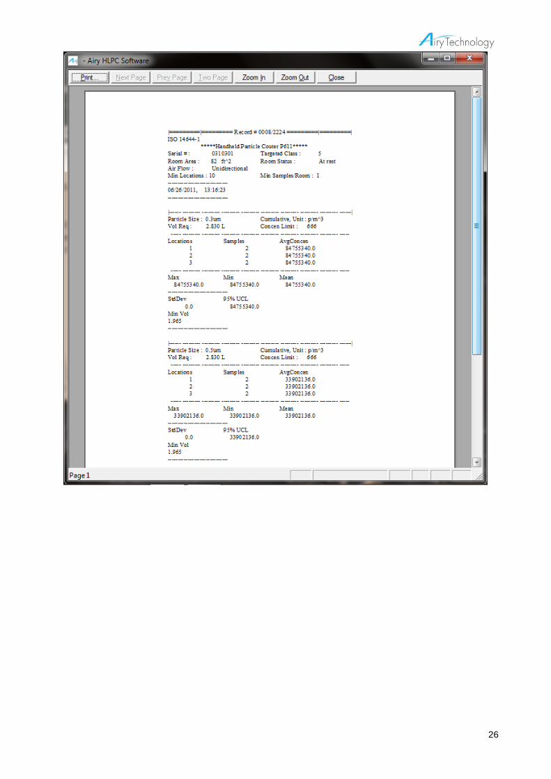
26

27
Calibration Please send the unit annually to Airy Technology or authorized service center for calibration.
Instructions on Charging Internal Battery A rechargeable battery for the clock is located inside the main body. When the instrument is turned ON, the battery is charged automatically. If the instrument has not been used for a while, the clock battery voltage will become low. In that case, the following screen will show up when the instrument is turned on. To fully charge the battery, connect the instrument to the AC adaptor and keep the instrument ON for at least 24 hours. The information above is applicable to the clock battery only and has nothing to do with the 4 x AA batteries that drive the instrument. Sampling is possible without charging the clock battery and the sampling data will be stored in the memory.
Set Date
00 :00:00
ENTER
Set Date
20 00 /01/01
ENTER
The battery for the clock is low.
Please refer to the Operation Manual.
The battery for the clock is low.
Please refer to the Operation Manual.

28
APPENDIX A
Specifications
Channel Sizes
Standard: 0.3, 0.5, 0.7, 1.0, 2.0, 5.0μm Standard: 0.3, 0.5, 1.0, 3.0, 5.0, 10.0 μm Standard: 0.3, 0.5, 0.7, 1.0, 2.5, 5.0 μm Standard: 0.3, 0.5, 1.0, 2.5, 5.0, 10.0 μm Optional: Other combinations (Please contact Airy Technology)
Counting Efficiency 50% at 0.3 μm; 100% for particles > 0.45 μm (per JIS)
Concentration Limits 4,000,000 particles / ft3 at 5% coincidence loss
Light Source Long life laser diode
Zero Count Level <1 count / 5 minutes (per JIS B9921)
Size Resolution <15% at 0.5 μm(per ISO 21501-4)
Flow Rate 0.1 CFM (2.83 LPM)
Flow Rate Control Automatic flow control
Calibration NIST traceable
Sample Probe/Tubing Isokinetic sampling probe, probe for tubing
Sampling Modes Manual, Automatic, ISO*1, GMP*
2, Cumulative/Differential, Count/Concentration
Sampling Time 1 second to 99 minutes 59 seconds (Configurable)
Sampling Frequency 1 to 9999 cycles or continuous (Configurable)
Sample Output Internal HEPA filter
Vacuum Source Internal pump
Communication Interface
USB
Data Storage 10000 sample records
Security 2-level password protection
Alarm Counts, Low battery, Flow, Laser
Display 3.5-inch 320 x 240 Color LCD
Power DC 5V 1A (Mini USB TYPE-B)
Battery 4 x AA
Battery Life Up to 4.5 hours of continuous use (LCD Backlight low, Included Ni-MH Battery)
Environmental Sensors Optional temperature/humidity probe
Dimensions (L x W x H) 178x90x47mm (without isokinetic inlet, temperature/humidity probe)
Weight 480g (without battery)
Standards JISB9921, ISO 21501-4
Warranty 2 year limited warranty
Operating Conditions 5° to 35°C 20% to 95%RH non-condensing
Storage Conditions -20° to 50°C Up to 98%RH non-condensing
Included Accessories Operating manual on CD, Quick guide, AC adapter, Isokinetic inlet, Probe for tubing, USB cable, Zero filter, Software, 4 x AA batteries with charger, Calibration certificate, Carrying case
Temperature and Relative Humidity Probe (Optional)
Temperature Range 32.0 to 122.0°F (0.0 to 50.0°C )
Temperature Accuracy 0.5°C
R/H Range 3.0 to 98.0%RH
R/H Accuracy 3%
*1 ISO 5-9 at 0.3-5.0 μm excluding ISO 5 at 5.0 μm, *2 GMP A-C in operation, A-D at rest