Handbook & Selection Guide for Computer-Based Data ... · Handbook & Selection Guide for...
177
Handbook & Selection Guide for Computer-Based Data Acquisition & Control Systems August, 2007 Neff Instrument Corporation 406 E. Huntington Dr. Monrovia, CA 91016-3423 TEL: 1-800-423-7151 or 1-626-357-2281 FAX: 1-626-303-2286
Transcript of Handbook & Selection Guide for Computer-Based Data ... · Handbook & Selection Guide for...

3
Handbook & Selection Guide
for Computer-Based Data Acquisition
& Control Systems
August, 2007
Neff Instrument Corporation 406 E. Huntington Dr.Monrovia, CA 91016-3423
TEL: 1-800-423-7151 or 1-626-357-2281
FAX: 1-626-303-2286

4

5
Table of Contents Summary of Neff Products ................................................................07 Product Features .................................................................................09 Table of Parameters ...........................................................................11 System 470 ........................................................................................17 470010 32-Bit TTL Input Card ..........................................................22 470011 16-Bit Isolated Discrete Input Card ......................................22 470013 32-Bit TTL Input/Output Card ..............................................23 470012 2-Channel Frequency or Period Input Card ..........................24 470015 2-Channel Wide Range Frequency or Period Input Card .....25 470014 ARINC-429 Card ..................................................................26 470030 32-Bit TTL Output Card .......................................................27 470031 8-Point Form “C” Relay Output Card ...................................27 470050 16-Channel Differential Multiplexer Card ............................28 470051 16-Channel Differential Mux Card w/ Open Source Detect .28 470052 16-Channel Differential Mux Card for 4-20mA ...................28 470059 16-Channel Differential Multiplexer Card ............................28 470054 4-Channel Bridge Conditioner/Mux Card ............................29 470055 4-Channel RTD Conditioner/Mux Card ...............................30 470056 16-Channel Transformer-coupled Mux Card ........................31 470070 2-Channel 16-Bit DAC Card ................................................32 470071 16-Channel 12-Bit DAC Card ..............................................32 470080 Screw Terminal Input Connector ..........................................33 470081 15-Channel Isothermal Connector ........................................33 470085 Programmable Voltage Calibration Card ..............................34 470103 Extender Card Set .................................................................35 470104 Display/Control Panel ...........................................................35 General Specifications .......................................................................36 System 470 Ordering Information .....................................................37 System 471 ........................................................................................39
470058 4-Channel Isolation Amplifier .............................................. 44 System 471 Specifications ................................................................. 44 System 471 Ordering Information ..................................................... 46 System 472 ........................................................................................ 47 472010 32-Bit TTL Input Card ......................................................... 51 472011 16-Bit Isolated Discrete Input Card ...................................... 51 472013 32-Bit TTL Input/Output Card ............................................. 52 472012 2-Channel Frequency or Period Input Card ......................... 53 472015 2-Channel Wide Range Frequency or Period Input Card ..... 54 472030 32-Bit TTL Output Card ....................................................... 55 472031 8-Point Form “C” Relay Output Card .................................. 55 472060 16-Channel Prog. Gain Amplifier/Multiplexer, 10Hz Filter 56
472064 16-Channel Prog. Gain Amplifier/Multiplexer, 100Hz Filter 56 472059 16-Channel Differential Multiplexer Card w/o Filter .......... 56 472070 2-Channel 16-Bit DAC Card ................................................ 58 472071 16-Channel 12-Bit DAC Card .............................................. 58 472081 15-Channel Isothermal Connector ........................................ 59 472103 Extender Card Set ................................................................. 59 General Specifications ....................................................................... 60 System 472 Ordering Information ..................................................... 61 System 495 ........................................................................................ 63 System 495 Specifications ................................................................. 69 System 495 Ordering Information ..................................................... 72 System 620 ........................................................................................ 75 Series 300 ..................................................................................... 78
620350 Input Conditioning Card ........................................... 79 620360 Strain Gauge Mode Card .......................................... 81 620361 RTD/Potentiometer Mode Card ............................... 82
620362 Thermocouple Mode Card ........................................ 83

6
Series 300 Specifications ...............................................................84 Series 300 Ordering Information ...................................................87 Series 500 ......................................................................................88 System 620 Local Configuration ...................................................92 620520 Local Dual-Bus Buffered Controller Assembly ...............93 620520 Local Configuration Specifications ..................................94 620526 Local Buffered Controller Card ........................................96 620526 Local Buffered Controller Card Specifications ................97 System 620 Remote Configuration ................................................98 620516A Serial Interface Control Assembly ...............................100 620516A Serial Interface Control Assembly Specifications .......101 620519 Remote Dual-Bus Controller Assembly .........................102 620519 Remote Dual-Bus Controller Assembly Specifications ..103 620527 Remote Buffered Controller Card ...................................105 620527 Remote Buffered Controller Card Specifications ...........106 Series 500 Function Cards ................................................................. 620511 Display/Control Panel .....................................................107 620530 32-Bit TTL Output Card .................................................108 620531 16-Point Relay Output Card ............................................109 620540 Eight-Channel Output Card ............................................110 620541 4-Channel Isolated DAC Card ........................................111 620552 Fiber Optic Link for Series 600 ......................................112 620560 32-Bit TTL Input Card ....................................................113 620561 32-Point Isolated DC Sense Card ...................................114 620562 4-Channel Counter Card .................................................115 620563 32-Point Isolated Latch Card ..........................................118 620564 32-Bit Isolated TTL Input Card ......................................119 620576 8-Port Serial Controller ...................................................120 .
Series 500 Ordering Information ................................................. 124 Series 600 .................................................................................... 127 Series 600 Specifications ............................................................. 132 Series 600 Ordering Information ................................................. 135 System 730 .................................................................................. 137 Filter Tables .........................................................................
Global Steps ............................................................ 140 Group A .................................................................. 142 Group B .................................................................. 142 Group C .................................................................. 143 Group D .................................................................. 143 Group E ................................................................... 144 Group F ................................................................... 144 Group G .................................................................. 145
Phase Tracking ............................................................................ 146 Noise vs Bandwidth ..................................................................... 146 730060 2-Channel Amplifier/Conditioner .................................. 147 730011 24-Bit Isolated TTL Input Card ........... .........................148 System 730 Specifications ........................................................... 149 System 730 Ordering Information ............................................... 151 Neff Support ............................................................................... 152 Spare Assemblies ....................................................................... 155 Appendix – Data Acquisition Systems ..................................... 161
Table of Contents

7
=içïJiÉîÉä=jìäíáéäÉñÉÇ=póëíÉãë=
===================jçÇÉä=======================j~ñK=`Ü~ååÉäë===================================== ÖÖêÉÖ~íÉ============================ çãéìíÉê=fåíÉêÑ~ÅÉ===========================================================================================================================qÜêçìÖÜéìí=====================póëíÉã=QTM============RNO=~å~äçÖ==============================================NMheò=================================p`pfI=dmf_=çê=bíÜÉêåÉí===
^ãéäáÑáÉêJmÉêJ`Ü~ååÉä=jìäíáéäÉñÉÇ=póëíÉãë==
==================jçÇÉä=======================j~ñK=`Ü~ååÉäë===================================== ÖÖêÉÖ~íÉ========================== çãéìíÉê=fåíÉêÑ~ÅÉ==========================================================================================================================qÜêçìÖÜéìí====================póëíÉã=SOML==================RNO======================================================NMMheò=============================p`pf=çê=m~ê~ääÉä===================pÉêáÉë=SMMG=====================================================================================póëíÉã=QTN=ïLQTNMRU=======NMOQ=========================================NMheò==================================p`pf=çê=dmf_==========================fëçä~íÉÇ=^ãéäáÑáÉê============================póëíÉã=QTO=ïLQTOMSM=======OMQU=========================================RMheò=================================p`pfI=dmf_=çê=bíÜÉêåÉí==========================mêÉ~ãéäáÑáÉê====G=oÉèìáêÉë=póëíÉã=SOMLpÉêáÉë=RMM=jÉ~ëìêÉãÉåí=~åÇ=`çåíêçä=póëíÉã=
Summary of Neff Products

8
=qê~åëÇìÅÉê=`çåÇáíáçåáåÖ=Epí~åÇ=~äçåÉF=
===================jçÇÉä=======================================================`çããÉåíë====================póëíÉã=SOMLpÉêáÉë=PMM======================dÉåÉê~ä=éìêéçëÉ=ÅçåÇáíáçåáåÖ=ïáíÜ=Åçåëí~åí=îçäí~ÖÉI=Åçåëí~åí=ÅìêêÉåí===========K===================================================== ================================= ÉñÅáí~íáçåI=ÄêáÇÖÉ=ÅçãéäÉíáçåI=ëÜìåí=~åÇ=oJ`~ä====================póëíÉã=QTMI=QTNI=QVR=~åÇ=TPM=======qÜÉëÉ=ëóëíÉãë=áåÅäìÇÉ=íê~åëÇìÅÉê=ÅçåÇáíáçåáåÖ=ïáíÜçìí=~ÇÇáíáçå~ä===================================================== =================================Ü~êÇï~êÉK
Summary of Neff Products (Continued)
^ãéäáÑáÉêJmÉêJ`Ü~ååÉä=kçåJjìäíáéäÉñÉÇ=póëíÉãë=EÅçåíáåìçìë=êÉÅçêÇáåÖF=
===================jçÇÉä======================j~ñK=`Ü~ååÉäë====================================^ÖÖêÉÖ~íÉ====================== === çãéìíÉê=fåíÉêÑ~ÅÉ========================================================================================================================qÜêçìÖÜéìí=====================póëíÉã=TPM====================RNO================== =================================Ojeò================================ =====p`pf==
qê~åëáÉåí=EÜáÖÜ=ëéÉÉÇF=póëíÉãë==
==================jçÇÉä======================j~ñK=`Ü~ååÉäë===j~ñK=`Ü~ååÉä=====j~ñK=låJ_ç~êÇ=píçê~ÖÉ=== çãéìíÉê=fåíÉêÑ~ÅÉ======================= ====================================================================p~ãéäÉ=o~íÉ====================póëíÉã=QVR=================== ORS==================Njeò======================SQjp~ãéäÉëLÅÜ~ååÉä===========p`pfI=dmf_=

9
50KHz Aggregate throughput rate 10Hz or 100Hz filtering Thermocouples (0.004° resolu-tion, 0.5°C accuracy) or other low frequency devices Bridge and RTD conditioning
TTL inputs Frequency measurements TTL and Relay Outputs Built-in automatic calibration SCSI, GPIB or Ethernet Interface 16-Bit resolution Expandable to 2048 channels
SYSTEM 472
SYSTEM 470
10KHz Aggregate throughput rate 10Hz or wideband filtering Thermocouples or other low frequency devices Bridge and RTD conditioning
TTL inputs and outputs Frequency measurements TTL and Relay Outputs Expandable to 512 channels SCSI, GPIB or Ethernet Interface 16-Bit resolution
10KHz Aggregate throughput rate Isolated amplifier per channel 300V CMV – Operating 4Hz filtering Thermocouples or other low frequency devices
Bridge and RTD conditioning TTL Inputs and outputs Frequency measurements TTL and Relay Outputs SCSI or GPIB Interface 16-Bit resolution Expandable to 1024 channels
SYSTEM 471

10
SYSTEM 730
For measuring medium frequency signals simultaneously with no phase shift 2MSample per second aggregate throughput rate 6Hz to 14KHz filtering in 87 steps Zero phase shift between channels Bridge conditioning
Programmable excitation Autobalance Built–in channel ID Built-in automatic calibration SCSI interface 16-Bit resolution Expandable to 512 channels
Programmable gain amplifier per channel 1MHz Per channel sampling rate 100Hz to 200KHz program selectable filtering High frequency signals from most sources Bridge conditioning
Programmable excitation Autobalance Up to 64MSamples memory per channel SCSI interface 14 or 16-Bit resolution Expandable to 256 Channels
SYSTEM 495
SYSTEM 620
Series 500/600/300
100KHz Aggregate throughput rate 1Hz, 10Hz, 100Hz or 1KHz program selectable filtering Thermocouples (0.004° resolution, 0.5°C accuracy) or other medium frequency devices Bridge and RTD conditioning
TTL inputs Frequency measurements TTL and Relay Outputs Built-in automatic calibration SCSI Interface 16-Bit resolution Expandable to 512 channels
SYSTEM 730

11
Parameter/Prod Signal Bandwidth
MAX Sample Rate —
Aggregate or Per Channel
Amplifier Per Channel
Built-in Calibration
Programmable or
Fixed Filter
On-Board Mem-ory
Bridge and RTD Conditioning
Comments
System 470 10Hz 10KHz Aggreg. No No Fixed 10Hz Ping-Pong Yes
470010 N/A N/A N/A N/A N/A N/A N/A Digital Input
470011 N/A N/A N/A N/A N/A N/A N/A Digital Input
470012 N/A N/A N/A N/A N/A N/A N/A Frequency In
470013 N/A N/A N/A N/A N/A N/A N/A Digital I/O
470014 N/A N/A N/A N/A N/A N/A N/A ARINC-429
470015 N/A N/A N/A N/A N/A N/A N/A Frequency In
470030 N/A N/A N/A N/A N/A N/A N/A Digital Output
470031 N/A` N/A N/A N/A N/A N/A N/A Relay Output
470050 10Hz 10KHZ Aggreg No No Fixed Filter No No 16-Chl Mux
470051 10Hz 10KHz Aggreg No No Fixed Filter No No Mux w/open source
470052 10Hz 10KHZ Aggreg No No Fixed Filter No No 4-20mA
470054 10Hz 10KHz Aggreg No No Fixed Filter No Bridge Cond. 4-Channel
470055 10Hz 10KHz Aggreg No No Fixed Filter No RTD Cond 4-Channel
470056 10Hz 10KHz Aggreg No No Fixed Filter No N/A 1000V CMV
470070 N/A N/A N/A N/A N/A N/A N/A Analog Output 2-Chl 16-Bit
470071 N/A N/A N/A N/A N/A N/A N/A Analog Output 16-Chl 12-Bit
470081 N/A N/A N/A N/A N/A N/A N/A Isothermal Connector
470085 N/A N/A N/A N/A N/A N/A N/A Calibration Card
470104 N/A N/A N/A N/A N/A N/A N/A Control Panel
System 470

12
Parameter/Prod Signal Bandwidth
MAX Sample Rate —
Aggregate or Per Channel
Amplifier Per Channel
Built-in Calibration
Programmable or
Fixed Filter
On-Board Mem-ory
Bridge and RTD Conditioning
Comments
System 471 4Hz 10KHz Aggreg. Yes No Fixed 4Hz Ping-Pong Yes
470010 N/A N/A N/A N/A N/A N/A N/A Digital Input
470011 N/A N/A N/A N/A N/A N/A N/A Digital Input
470012 N/A N/A N/A N/A N/A N/A N/A Frequency In
470013 N/A N/A N/A N/A N/A N/A N/A Digital I/O
470015 N/A N/A N/A N/A N/A N/A N/A Frequency In
470030 N/A N/A N/A N/A N/A N/A N/A Digital Output
470031 N/A` N/A N/A N/A N/A N/A N/A Relay Output
470058 4Hz 10KHz Aggreg Yes – Prog Gain No Fixed 4Hz No Yes 4-Chl 300V CM
470070 N/A N/A N/A N/A N/A N/A N/A Analog Output 2-Chl 16-Bit
470071 N/A N/A N/A N/A N/A N/A N/A Analog Output 16-Chl 12-Bit
470085 N/A N/A N/A N/A N/A N/A N/A Calibration Card
471104 N/A N/A N/A N/A N/A N/A N/A Control Panel
System 471

13
Parameter/Prod Signal Bandwidth
MAX Sample Rate —
Aggregate or Per Channel
Amplifier Per Channel
Built-in Calibration
Programmable or Fixed Filter
On-Board Mem-ory
Bridge and RTD Conditioning
Comments
System 472 10Hz, 100Hz 50KHz Aggreg. No No Fixed 10Hz, 100Hz
Ping-Pong Yes
472010 N/A N/A N/A N/A N/A N/A N/A Digital Input
472011 N/A N/A N/A N/A N/A N/A N/A Digital Input
472012 N/A N/A N/A N/A N/A N/A N/A Frequency In
472013 N/A N/A N/A N/A N/A N/A N/A Digital I/O
472015 N/A N/A N/A N/A N/A N/A N/A Frequency In
472030 N/A N/A N/A N/A N/A N/A N/A Digital Output
472031 N/A` N/A N/A N/A N/A N/A N/A Relay Output
472052 10Hz 10KHZ Aggreg No No Fixed,10Hz No No 4-20mA
472060 10Hz 50KHz Aggreg Yes – Prog. Gain Yes Fixed, 10Hz No No 16-Chl
472064 100Hz 50KHZ Aggreg Yes – Prog. Gain Yes Fixed, 100Hz No No 16-Chl
472070 N/A N/A N/A N/A N/A N/A N/A Analog Output 2-Chl 16-Bit
472071 N/A N/A N/A N/A N/A N/A N/A Analog Output 16-Chl 12-Bit
472081 N/A N/A N/A N/A N/A N/A N/A Isothermal Connector
472104 N/A N/A N/A N/A N/A N/A N/A Control Panel
System 472

14
Parameter/Prod Signal Bandwidth
MAX Sample Rate —
Aggregate or Per Channel
Amplifier Per Channel
Built-in Calibration
Programmable or
Fixed Filter
On-Board Mem-ory
Per Channel
Bridge and RTD Conditioning
Comments
System 495 To 200KHz 1MHz Per Chl Yes No Programmable To 64MS/Chl Bridge
495070 To 200KHz 250KHz Per Chl Yes R-Shunt Programmable 1MSample Bridge Auto-balance
495071 To 200KHz 250KHz Per Chl Yes R-Shunt Programmable 16MSample Bridge Auto-balance
495072 To 200KHz 250KHz Per Chl Yes R-Shunt Programmable 32MSample Bridge Auto-balance
495073 To 200KHz 250KHz Per Chl Yes R-Shunt Programmable 64MSample Bridge Auto-balance
495080 To 200KHz 1MHz Per Chl Yes R-Shunt Programmable 1MSample Bridge Auto-balance
495081 To 200KHz 1MHz Per Chl Yes R-Shunt Programmable 16MSample Bridge Auto-balance
495082 To 200KHz 1MHz Per Chl Yes R-Shunt Programmable 32MSample Bridge Auto-balance
495083 To 200KHz 1MHz Per Chl Yes R-Shunt Programmable 64MSample Bridge Auto-balance
System 495

5
Parameter/Prod Max Signal Bandwidth
MAX Sample Rate —
Aggregate or Per Channel
Amplifier Per Channel
Built-in Calibration
Programmable or
Fixed Filter
On-Board Mem-ory
Bridge and RTD Conditioning
Comments
System 620
Series300 N/A N/A N/A N/A N/A N/A Yes Transducer Cond
620300 N/A N/A N/A N/A N/A N/A Exc Supply V or I
620350 N/A N/A N/A N/A N/A N/A Exc. Regulators 4 – Channels
620360 N/A N/A N/A N/A N/A N/A Bridge Mode Cd 1 – Channel
620361 N/A N/A N/A N/A N/A N/A RTD Mode Cd 1 – Channel
Series 600 1KHz 100KHz Aggreg Yes Yes N/A No No Control Assy
620650 1KHZ N/A Yes – Prog Gain Yes Prog. 2-Pole No No 4 – Channel
620654 1KHz N/A Yes – Prog Gain Yes Prog. 6-Pole No No 4 – Channel
Series 500 N/A 300KHz Aggreg N/A N/A N/A N/A N/A Controller
620530 N/A N/A N/A N/A N/A N/A N/A Digital Output
620531 N/A N/A N/A N/A N/A N/A N/A Relay Output
620534 N/A N/A N/A N/A N/A N/A N/A Clock
620540 N/A N/A N/A N/A N/A N/A N/A Analog Output
620541 N/A N/A N/A N/A N/A N/A N/A Isol Analog Out
620560 N/A N/A N/A N/A N/A N/A N/A Digital Input
620561 N/A N/A N/A N/A N/A N/A N/A Isol DC Sense
620562 N/A N/A N/A N/A N/A N/A N/A Frequency Card
620563 N/A N/A N/A N/A N/A N/A N/A Isol Dig Latch
620564 N/A N/A N/A N/A N/A N/A N/A Isol Dig Input
System 620

16
Parameter/Prod Max Signal Bandwidth
MAX Sample Rate —
Aggregate or Per Channel
Amplifier Per Channel
Built-in Calibration
Programmable or
Fixed Filter
On-Board Mem-ory
Bridge and RTD Conditioning
Comments
System 730 2MS/Sec Aggreg Yes Yes Programmable Ping-Pong Yes
730060 14KHz 37KHz/Chl Yes Yes Programmable 108 Steps
Digital Filter
No Bridge Conditioning
Zero phase shift between channels
730011 N/A N/A N/A N/A N/A N/A N/A Digital Input
System 730

17
==
pÉÅíáçå=ff===
póëíÉã=QTM====
a~í~=^Åèìáëáíáçå=póëíÉã===

18
======o Low-Level Multiplexed System o 256 Analog Inputs; Expandable to 512 o Throughput Rates to 10 KHz o Fully Guarded Differential Inputs o Analog and Digital Function Cards
o=====10 Megohm Input Impedance, Power On or Off o 16-Bit Resolution Including Sign o Full scale Inputs from ±5 mV to ±10.24 V o Voltage Insertion Calibration o SCSI, IEEE-488 or Ethernet Interface
Introduction The Neff System 470 Data Acquisition System is a complete moderate-speed data acquisition system for use in computer-based applications. The System 470 is designed primarily for computer automated data acquisition in test facilities, laboratories, and indus-trial plants or wherever a moderate-speed data acquisition system is required. The System 470 is designed to accept analog inputs ranging from ±5 mV to ±10.24 V full scale. Sensors such as strain gauges, RTDs, potentiometers and thermocouples can be input directly to one of the System 470 function cards thus eliminating any need for external signal conditioning.
System 470 consists of a seven-inch high, 19-inch wide enclosure with power supply, backplane wiring, I/O Control Logic printed cir-cuit card, Analog Subassembly printed circuit card, and 16 I/O card slots that accept any combination of System 470 function cards. A Control/Display panel is optional and an expansion assembly is available to extend function card capacity to 32. The maximum number of channels or data points to be serviced depends on the type of function cards used. Thirty-two 16-channel Multiplexer cards, for example, provide 512 channels of analog input while a full comple-ment of 32-bit TTL Input cards accommodate 1024 single data points. Most analog input cards have filters to reject superimposed noise and unwanted signal frequencies. The filtered signals are multiplexed onto the analog function card bus by CMOSFET switch packages.
System 470 Data Acquisition System
System 470 Data
Acquisition System
Host
Processor Analog Inputs Analog Outputs Discrete Inputs Discrete Outputs
SCSI or
IEEE-488
Interface

19
Function Cards 470010 32-Bit TTL Input 470011 16-Bit Isolated Digital Input 470012 Two Channel Frequency or Period Input 470013 32-Bit TTL Input/Output 470014 ARINC - 429 Controller 470015 2-Chl Wide Range Frequency or Period Input 470030 32-Bit TTL Output 470031 Eight-Point Form-C Relay Output 470032 Scanivalve Controller 470050 16-Channel Differential Multiplexer 470051 16-Channel Differential Multiplexer with Open Source Detection 470052 16-Channel Differential Multiplexer with Conditioning for 4-20mA Input 470054 Four-Channel Bridge Conditioning 470055 Four-Channel RTD Conditioning Multiplexer 470056 16-Channel Transformer-Coupled Multiplexer 470059 16-Channel Mux, Direct Input 470070 Two-Channel 16-Bit DAC Output 470071 16-Channel 12-Bit DAC Output 470085 Calibration Card
System 470 Data Acquisition System (Continued)
Front Access to all Cards Function cards are accessed by open-ing the hinged front panel and can be changed or moved without disturbing I/O cabling. All I/O connections are made at the rear panel of the system. Both sol-der type and screw type input connectors are available. Guarded Input The input guard environment--containing the function cards, input pro-grammable gain amplifier (PGA), associ-ated address logic, and input power sup-ply--is driven at a common-mode poten-tial derived from the input signal. This technique provides 120 dB common mode rejection without shields. The common mode potential is taken from the input signal by an amplifier having very high input impedance to ensure that common mode impedance is not de-graded. Digital addresses, gain codes, and control signals are optically coupled to maintain high common mode isolation.
Programmable Gain Amplifier The multiplexed analog input signals are applied to the PGA. This is a differ-ential amplifier set to a gain of either 1 or 64 by the decoded gain bits of the in-put control word and located within the input guard environment to enhance common mode rejection. A second-stage differential amplifier, with gains of 1, 2, 4, 8, 16, or 32 (programmed simultaneously with the PGA) is responsible for maintaining common mode isolation. Overall system gain is the product of the gain of the two amplifiers. Input ranges of ±5 mV to ±10.24 V can be individually pro-grammed for each channel.

20
System 470 Data Acquisition System (Continued)
Post Filter Sample rates of 1 KHz or 10 KHz are switch selectable. As the sampling rate is changed, the post filter adjusts the bandwidth to mini-mize output noise and optimize performance at each sample rate. Ag-gregate throughput rate is controlled by programming the scan period. Sample & Hold For accurate conversion of the input signal, a sample and hold am-plifier is positioned ahead of the analog-to-digital converter. At a fixed time in the conversion cycle, the amplifier switches to hold mode to provide a constant input to the ADC.
Auto-Zero
An automatic zero circuit compensates for zero offset error gener-ated by the PGA or sample and hold amplifiers. The circuit tracks the output of the sample and hold amplifier and generates an equal and op-posing voltage that is effectively subtracted from the sample and hold output voltage for input to the ADC. Internal I/O Bus A 16-bit internal I/O bus interconnects the ADC, digital I/O serial-to-parallel converter, and the microcomputer. Two connectors are used to extend the internal I/O bus to an expansion assembly and another links the bus to the optional Display/Control panel.
FunctionCards
MUX
PGA S/H
Auto Zero
16-BitADC
uP
Control/DisplayPanel
I/O Interfaceto Host Computer

21
System 470 Data Acquisition System
Operating Modes System 470 provides two basic data acqui-sition operating modes to read input data: 1. Single Buffer Mode 2. Continuous or “Ping-Pong” Buffer Mode In addition, an output mode is provided to output data from the system. Each data buffer is “stamped” with the current real-time (or scan time being kept by the firmware). Mode usage will depend on host computer capability, the interface used, and the application requirements. Following are basic mode descriptions. Single Buffer Mode. The single buffer mode of data acquisition is a start-stop synchronous configuration wherein the host computer initi-ates each data acquisition cycle. Initially, the host computer downloads a channel scan list to System 470. The scan list consists of the channel numbers of the devices to be read (function cards) as well as the PGA gain codes required for analog input channels. The scan list defines one scan or pass through the block of input channels to be read. The host computer then defines a number
of scans to be run and a scan period that deter-mines the rate at which the scans are initiated. System 470 then partitions a data buffer area in RAM for storing the returned data. After this initial setup phase, the host computer issues a start command to System 470 to begin. System 470 executes the speci-fied number of scans and places the resultant data into the data buffer. When the last data word has been loaded into the data buffer, System 470 halts further data acquisition and signals the host that the data buffer is ready. The host reads the data buffer and may then issue a go-again command to repeat the cycle. The single buffer mode is adequate for many applications. Because the host starts each data acquisition cycle, there is no danger that it will be overrun. However, there are gaps in the data while System 470 is waiting for the host to read the data buffer. Maximum data sampling rate is also limited by the time required for the host to read the data buffer. Ping Pong Buffer Mode. The Ping Pong mode of operation permits faster sample rates
by overcoming the timing limitations of the single buffer mode. In this mode, System 470’s RAM is partitioned into two data buff-ers. A/D data and digital data are returned to one data buffer. When that buffer is filled, System 470 signals the host that the buffer is ready. Without waiting for the host to read the buffer, System 470 loads the uninterrupted input data into the second buffer. The host can transfer the data from the first buffer at any time prior to the completion of the second buffer or it may choose to ignore a buffer and allow it to be overwritten by subsequent data. Because of the time stamping feature, data in-tegrity is maintained even when buffers are skipped. Output Mode. Output lists, defining control functions to be output by System 470, are block transferred from the host to the System 470. The system’s microcomputer executes the list immediately or, if a scan list is in pro-gress, when the current scan is completed. 32 Bit TTL Input - 470010 This card reads 32 bits of input TTL data

22
as two groups of 16 bits each. A Hold output signal handshakes with the device being read. Hold is a 10 uS pulse of selectable polarity as-serted when either 16-bit group is to be read. This feature is especially useful when reading digitally-coded levels from a counter, DVM, clock, etc., which, if read in its transitional state, would result in am-biguous data. An Enable input allows the user to decide when to update the card’s input register. All inputs and outputs interface with either standard or low power TTL logic. Jumper wires select positive true or negative true logic levels. Specifications Inputs High-Level Input Voltage: 2.0 V min; 5.0 V max Low-Level Input Voltage: 0.0 V min; 0.8 V max High-Level Input Current: 20 uA max Low-Level Input Current: - 400 uA max Enable: 1000 ohm pull-up resistor Outputs High-Level Output Voltage: 5.25 V max Low-Level Output Voltage: 0.4 V max High-Level Output Current: 250 uA max Low-Level Output Current: 40 mA max
16 - Bit Isolated AC/DC Input - 470011
The 16-Point AC/DC Input card provides isolated inputs for 16 channels with voltage levels from 12 V to 48 V, ac or dc. Inputs are read as a 16-bit digital word with positive-true or zero-true logic se-lected by jumper placement. Up to 1000 V common mode can be ap-plied between inputs and ground.
Specifications Input Current: 21 mA @ 48 V 8.1 mA @ 24 V 1.4 mA @ 12 V Common Mode 1000 V max Voltage: Response Time: 50 mS
Discrete Input Cards

23
Discrete Input Cards (Continued)
32 Bit TTL Input/Output - 470013 The 32-Point TTL Input/Output card provides a 32-bit TTL level bus for user definition. The bus is divided into four bytes, each of which may be programmed separately as either input or output. Output data is loaded in word form. Writing to Channel 08 will load output data into output bytes 0 and 1, where byte 0 is equivalent to bits 0-7 and byte 1 is equivalent to bits 8-15. Writing to Channel 09 will load output data into output bytes 2 and 3. Specifications Inputs: High Level Vin: 3.15 V min, 5 V max Low Level Vin: -1.5 V min, - 0.9 V max Outputs: High Level Vout: 2.4V min High Level Iout: -2.6 mA max Low Level Vout: 0.5V max Low Level Iout: 24 mA max

24
Frequency, Period and Counter Input
Two-Channel Frequency or Period Input 470012
The Two-Channel Frequency or Period Input card accommodates inputs from tachometers, flowmeters, or other frequency-related de-vices. Frequency or period measurements or straight event counting are selectable by switches on the card. For flexibility, each channel accepts two types of inputs. One set of input terminals, for TTL logic levels, is optically coupled. The other input is intended for use with signal levels that vary with frequency. An event zero-crossing detector accepts inputs from ±200 mV to ±100 V at frequencies to 100 KHz. A crystal-controlled clock provides accurate time bases for meas-urements on both channels while each channel has its own 32K counter. After each measurement, the counter is reset. Frequency measurement involves counting the number of input pulses occurring between clock pulses. By means of manual switches on each channel, the user can select measurement mode, clock frequency, and select counting to occur on the leading or trailing edge of an input pulse. Specifications Accuracy Frequency Mode: ±0.01% Of reading ±1 count Period Mode: ±0.01% of reading ± input risetime (0.6 to 4 V) transition)
Ranges Isolated TTL Input Input Voltage: ±5.25 V max Sink Current: 16 mA max Common Mode: ±300 V max Frequency: dc to 350KHz Non-isolated Input Input Voltage: ±200 mV min; ±100 V max Input Impedance: 50KOhms Frequency: dc to 100 KHz
Mode Time Base FS Range Resolution (1 count =)
Frequency 0.1 sec 1 Sec 10 Sec
327 KHz 32.7 KHz 3.27 KHz
10 Hz 1 Hz 0.1 Hz
Period 100 KHz 10 KHz 1 KHz
327 mSec 3.27 Sec 32.7 Sec
10 µSec 100 µSec 1.0 mSec
Count Counts 0 to 32767
25
Frequency, Period and Counter Input (Continued)
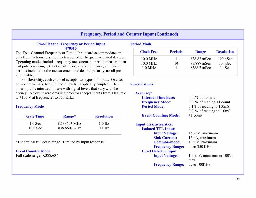
Two-Channel Frequency or Period Input 470015
The Two-Channel Frequency or Period Input card accommodates in-puts from tachometers, flowmeters, or other frequency-related devices. Operating modes include frequency measurement, period measurement and pulse counting. Selection of mode, clock frequency, number of periods included in the measurement and desired polarity are all pro-grammable. For flexibility, each channel accepts two types of inputs. One set of input terminals, for TTL logic levels, is optically coupled. The other input is intended for use with signal levels that vary with fre-quency. An event zero-crossing detector accepts inputs from ±100 mV to ±100 V at frequencies to 100 KHz. Frequency Mode
*Theoretical full-scale range. Limited by input response. Event Counter Mode Full scale range, 8,388,607
Period Mode
Specifications: Accuracy: Internal Time Base: 0.01% of nominal Frequency Mode: 0.01% of reading ±1 count. Period Mode: 0.1% of reading to 100mS. 0.01% of reading to 1.0mS Event Counting Mode: ±1 count Input Characteristics: Isolated TTL Input: Input Voltage: ±5.25V, maximum Sink Current: 16mA, maximum Common-mode: ±300V, maximum Frequency Range: dc to 350 KHz Level Detector Input: Input Voltage: 100 mV, minimum to 100V, max. Frequency Range: dc to 100KHz
Gate Time Range* Resolution
1.0 Sec 10.0 Sec
8.388607 MHz 838.8607 KHz
1.0 Hz 0.1 Hz
Clock Fre- Periods Range Resolution
10.0 MHz 10.0 MHz 1.0 MHz
1 10 1
838.87 mSec 83.887 mSec 8388.7 mSec
100 ηSec 10 ηSec 1 µSec

26
Controller Cards
ARINC-429 Controller 470014
ARINC-429 Controller, 470014, is used to interface the System 470 to the ARINC-429, Mark 33 Digital Information Transfer System (DITS) bus. It mounts in a standard System 470 function card slot and pro-vides 4 receiver and 4 transmitter channels for communication with compatible devices.
Features; * Four receiver channels * Four transmitter channels * Received data sorted by Label * Data packet for interdependent Labels * Received data read by 470 scan list * SDI support * Both fast and slow bit rates supported

27
Discrete Output Cards
32-Bit TTL Output--470030 The 32-Bit TTL Output card provides two 16-bit outputs for driv-ing TTL-compatible loads or other loads not exceeding output capabil-ity (30 V maximum; 40 mA maximum). Dual-rank registers permit the simultaneous updating of all outputs. All outputs are open-collector gates with pull-up resistors to the in-ternal 5 V supply for driving standard TTL or 5 V CMOS loads. Placement of a jumper permits use of an external voltage source up to 28 V. Outputs can then interface to high voltage CMOS logic or be used to drive relay coils, lamps, or other loads not exceeding 40 mA. Output polarity of each group of eight outputs is determined by jumper placement. This allows the user to arrange logic polarity to any desired power-up/reset condition required by the application. Specifications Open Circuit Voltage: +30 V max Sink Current: -40mA max
Eight-Point Form-C Relay Output--470031 The Eight-Point Form-C Relay Output card provides eight three-wire form-C outputs (normally open, normally closed, and common) to drive various control devices. Each relay has a "set" and "reset" coil and is magnetically latches in its current state at power down. Eight control bits are used to address and control the relays individually. Dual-rank registers permit simultaneous updating of all relay states. Specifications Initial Contact 30 milliOhm, max Resistance: Maximum Contact 2000 VA, 150 W (resistive) Switching Power: Maximum Switching 250 VAC Voltage: Maximum Switching 8 Amperes Current: Breakdown Voltage: 1000 V between open contacts, 1000 V between contacts and ground Set/Reset Time: 8 ms (approximately)

28
System 470 offers four types of Differential Multiplexer cards. Three feature input filter, CMOS/FET multiplexer switch and 16 dif-ferent inputs. Input ranges from ±5 mV to ±10.24 V full scale. Card 470050 is the basic differential multiplexer; the others offer alternate input configurations. Card 470051 provides open source de-tection, 470052 is equipped with shunt resistors for measuring 4-20 mA inputs, 470059 has direct input (w/o filter). Except for 470059, the cards are equipped with two-pole, passive R-C filters having a terminal rolloff of 12 dB/octave. The -6 dB corner frequency of 10 Hz provides greater than 25 dB attenuation of input noise components at the 60 Hz power line frequency. The open source detection feature recognizes open thermocouples, broken wires and high resistance or open input connections. A 10 nA current is output at the channel input terminals causing an overload in-dication (off scale) reading if an open or high resistance input circuit is present. Card 470052 has 250 ohm shunt resistors on each channel for sensing 4-20 mA input. Specifications: (System 470 with 47005X Cards Installed) Number of 16 guarded differential input channels per Channels: card. Input sources may be grounded or floating. Input Impedance: 10 MegOhms; power on or off. Input Filter: Passive RC filter on each channel; 2-pole, low- pass with 12 dB/octave terminal slope; -6dB at 10 Hz and -30 dB at 100 Hz. Maximum Input ±30 V differential or common mode Voltage:
Common Mode 120 dB (80 dB plus gain in dB to 120 dB max); Rejection: dc to 60 Hz with 350 Ohm source imbalance. Common Mode ±10 V operating. Voltage: ADC Resolution: 16-bits, including sign. Gain Accuracy: ±0.05%. Gain Stability: ±(0.01% + 0.003%/°C). Linearity: ±(0.02% + ½LSB). Static Crosstalk: 120 dB between channels, dc to 1 KHz with 350 ohm source; 10 V maximum non-overloaded input. Zero Offset: ±10 uV, channel-to-channel. Zero Stability: ±(5 uV RTI + 1.25 mV RTO) ±(0.5 uV/°C RTI + 0.1 mV/°C RTO). Noise: Noise = [(RTI x Gain)² + RTO²]1/2
=
=
16-Channel Differential Multiplexer Cards
Throughput Rate RTI RTO
10 KHz 1 KHz
8.5 uV 3.7 uV
1.5 mV 1.5 mV

29
4 Channel Conditioner/Multiplexer 470054
For bridge measurements using one, two, or four active arms, this
card provides a precision excitation supply, balance control, and termi-nals for bridge completion, balance limit, and calibration resistors on each channel. Bridge completion resistor kits are available, see below. The card includes multiplexer switches and a standard two-pole RC filter, providing the same performance specifications as the 470050 16-Channel Multiplexer. One step shunt resistor calibration is program-mable. Up to eight input leads plus shield can be used, giving the user the option of local or remote sensing. Specifications - Excitation Supply Voltage: Selectable; 5 V or 10 V. Current: 100 mA max/channel; short circuit protected. 3.2 Amperes per control or expansion assembly. Line Less than 0.01% or 200 uV, whichever is greater, Regulation: for ±10% line voltage variation. Load Less than 0.01% or 200 uV, whichever is greater, Regulation: for a no-load to full load change. Stability: ±0.01% at constant temperature; ±0.005%/°C. Noise: Less than 200 uV pk-pk in 10KHz bandwidth. Bridge Terminals provided for four completion resistors. Completion: Test Front mounted jacks for monitoring excitation Points: and output voltages.
Bridge 350 Ohm or 120 ohm resistor kit: includes Completion three bridge completion and one balance Resistor Kits: limit resistor. Specifications - System 470 ADC Resolution: 16-bits, including sign. Gain Accuracy: ±0.05%. Gain Stability: ±(0.01% + 0.003%/°C). Linearity: ±(0.02% + ½LSB). Static Crosstalk: 120 dB between channels, dc to 1KHz with 350 ohm source; 10 V maximum non-overloaded input. Zero Offset: ±10 uV, channel-to-channel. Zero Stability: ±(5 uV RTI + 1.25 mV RTO) ±(0.5 uV/°C RTI + 0.1 mV/°C RTO). Noise: Noise = [(RTIxGain)2+RTO2]1/2
Bridge Conditioner/Multiplexer
Throughput Rate RTI RTO
10 KHz 1 KHz
8.5 uV 3.7 uV
1.5 mV 1.5 mV

30
Four Channel RTD Conditioner/Multiplexer 470055
The Four Channel RTD Conditioning/Multiplexer provides direct connection of 2, 3, and 4-wire, 100 Ohm RTDs in a balanced bridge configuration. The card can be configured by jumper placement to ac-commodate current-excited 4-wire RTDs of values to 1 KOhm. The card includes multiplexer switches, 10 Hz filter, and excitation source adjustment for each channel. Excitation current is 0.5 mA in the bridge configuration, or 1 mA in the constant current configuration, resulting in very low self-heating errors in the RTDs. Specifications - Excitation Supply Current: 1.0 mA adjustable +/- 1% Compliance Voltage: 0 to 3.5 Volts Line Regulation: Less than 0.01% or 0.1mA, for a ±10% line voltage variation. . Response Time: Output settles to within 1% of setting in less than 50uSec with a no-load to full- load change. Stability: ±0.01% at constant temperature; ±0.005%/°C. Output Impedance: 1 MegOhms minimum Ripple: Less than 0.2uA peak-to-peak over the bandwidth dc to 1KHz.
Test Points: Front mounted jacks for monitoring excitation and output voltages. Specifications - System 470 ADC Resolution: 16-bits, including sign. Gain Accuracy: ±0.05%. Gain Stability: ±(0.01% + 0.003%/°C). Linearity: ±(0.02% + ½LSB). Static Crosstalk: 120 dB between channels, dc to 1 KHz with 350 ohm source; 10 V maximum non-overloaded input. Zero Offset: ±10 uV, channel-to-channel. Zero Stability: ±(5 uV RTI + 1.25 mV RTO) ±(0.5 uV/ °C RTI + 0.1 mV/°C RTO). Noise: Noise = [(RTIxGain)2+RTO2]1/2
RTD Conditioner/Multiplexer
Throughput Rate RTI RTO
10 KHz 1 KHz
8.5 uV 3.7 uV
1.5 mV 1.5 mV

31
16 Channel Transformer Coupled Multiplexer 470056
The Transformer-Coupled Differential Multiplexer provides 16 channels of analog input for System 470. Each channel is galvanically isolated from other channels and from ground. Common mode volt-ages of up to ±1000 V are rejected. Each channel features fully-guarded differential input allowing op-eration from either grounded or floating input sources. Two-pole, low-pass filters approach 12 dB/octave terminal rolloff on each channel. Specifications: (System 470 with 470056 Card Installed) Number of 16 guarded differential input channels. Input Channels: sources may be floating or grounded. Input Filter: Passive RC filter on each channel two-pole, low -pass with terminal slope approaching 12 dB/octave; -6 dB at 10 Hz and -30 dB at 100 Hz. Input Impedance: 5 MegOhms, minimum; power on or off. Isolation: Less than 100 pF from any input terminal to ground. Maximum Input ± 30 V differential, without damage. Voltage: Common Mode ±1000 V dc or peak ac. Voltage:
Common Mode 100 dB + gain in dB to 120 dB max; dc to Rejection: 60 Hz with up to 350 ohms source imbalance Full Scale Accuracy: ±0.05% of full scale at constant temperature, ±0.003%/°C. Linearity: Less than 0.05% of full scale deviation from best fit straight line through zero and full scale. Zero Stability: ±(5 uV RTI + 1.25 mV RTO) at constant temperature; ±(0.5 uV/°C RTI ± 0.1 mV/°C RTO). Zero Offset: ± 10 uV channel-to-channel. Noise (3 Sigma): 10 uV peak RTI + 1.5 mV RTO. Resolution: 16-bit resolution; 0.003% FS. Static Crosstalk: 120 dB between any two channels; dc to 1 KHz. Dynamic Crosstalk: 110 dB to next channel in scan including over load (up to 30 V input) and full scale range changing. Sample Rate: 20 samples/second/channel max to meet all specifications, with up to 350 ohm source resistance. Note: System 470 sample rate must be set to 10 KHz.
High Common Mode Voltage Multiplexer

32
Two Channel 16-Bit DAC 470070
The Two Channel DAC Output card provides two channels of ana-
log output from System 470. Each channel consists of a 16-bit digital-to-analog converter (DAC) scaled to deliver ±10.24 V output. Each output can deliver 20 mA of load current with remote sense leads pro-vided to cancel line drops. Dual-rank registers permit simultaneous updating of both channels. Specifications Output Voltage: ±10.24 V full scale. Output Current: ±20 mA. Accuracy: ±0.02% of full scale. Stability: ±0.005% of FS at constant temperature; 0.001%/°C over 0 to 50°C. Resolution: 0.00305% FS/count (1 part in 32,768). Noise: Less than 500 uV in 10 KHz bandwidth
Sixteen Channel 12-Bit DAC 470071
The 16 Channel DAC Output card provides 16 channels of analog output from System 470. Each channel consists of a 12-bit digital-to-analog converter (DAC) scaled to deliver ±10.24 V output. Each out-put can deliver 20 mA of load current with remote sense leads pro-vided to cancel line drops. Specifications Output Voltage: ±10.24 V full scale. Output Current: ±20 mA. Accuracy: ±0.02% of full scale. Stability: ±0.005% of FS at constant temperature; 0.001%/°C over 0 to 50°C. Resolution: 0.05% FS/count (1 part in 2,048). Noise: Less than 500 uV in 10 KHz bandwidth.
Analog Output

33
Screw Terminal I/O Connector 470080
Standard termination of I/O cables is by solder connections to I/O
card edge connectors. With the optional screw terminal input card, leads are terminated at “quick plug-in” copper receptacles secured by flush mounted set screws. All terminals are clearly identified for each type of I/O card.
16-Channel Isothermal Connector
470081 The Isothermal Connector provides the means of terminating ther-mocouple input cables at the rear panel of the System 470. It can be used with any of the following analog input cards. 470050 16 Channel Multiplexer 470051 16 Channel Multiplexer with Open Source Detection 470056 16 Channel Transformer-Coupled Multiplexer The Isothermal Connector plugs directly into the input (edge) con-nector of the analog input card. Thermocouple cables are brought into 15 sets of screw terminals on the connector, corresponding to multi-plexer input channels 1 through 15. A temperature transducer in the connector supplies a reference voltage to channel 0 that is proportional to the termination temperature. The termination temperature and the type of thermocouple on each channel is the information the CPU requires to convert the
thermocouple voltage to temperature. Since the con-version is under control of the CPU, thermocouple types can be mixed. Specifications Reference Temperature: 1 mV/°C (Channel 00). Reference Temperature ±0.25°C over the range of 10°C to 45° Accuracy: Thermocouple Inputs: Channels 01 through 15. Temperature Gradient: 0.1°C across terminations.
I/O Connectors
Screw Terminal Connector
Isothermal Connector

34
Calibration Card 470085
The Calibration Card is a programmable dc voltage source used for calibration of the System 470. It can be installed in any function card connector. The card’s output voltage is read through its analog multi-plexer and is also output on the user I/O connector for use by external devices. Output voltage is programmable in three ranges from ±102.4 mV to ±10.24 V full scale. The voltage is derived from an on-board DAC driven by a 15-bit (plus sign) digital word from the host computer. The Calibration Card’s address and voltage level is included in the output list formatted by the host and transferred to System 470. The card’s address is included in the input scan list to read back the calibration voltage to the system.
Specifications Accuracy: ±0.025% FS + 10 uV. Output Impedance: 50 ohms. Load Resistance: 500 KOhm minimum for specified accuracy.
Calibration Card
Range Resolution
±10.24 V ±1.024 V
± 102.4 mV
312.5 uV 31.25 uV 3.125 uV

35
Extender Cards
470103 This set of two extender cards is used for calibration and servicing of the printed circuit cards in the system. It allows access to card com-ponents and test points under operating conditions.
Control/Display Panel
470104 For normal operation, the front panel’s Remote/Local switch is set for remote mode. The Remote indicator is turned on and System 470 operates under control of the host computer. When the Remote/Local switch is pressed again , the indicator turns off and the front panel con-trols are activated. Local mode is useful for installation, testing, and calibration. By means of a 16-bit switch register and corresponding LED dis-play, the operator can write addresses and data to the System 470’s in-ternal Device I/O bus and read data from the bus. In addition, the user can select continuous scanning or a trap mode in which any channel can be selected for constant monitoring and updating each time the channel is sampled.
System 470 Accessories

36
System 470 General Specifications
Power 105 V to 130 V (220 V to 250 V), 50 to 400 Hz, Requirements: 250 W. Environmental 0°C to 50°C, 90% relative humidity, non-Requirements: condensing. Will withstand shock and vibration of normal shipping and handling of laboratory equipment. Cooling To be mounted in cabinet with unobstructed Requirements: airflow and equipped with a 300 cfm blower. Size: 7-inch panel height in 19" rack; 23-inch depth behind front panel. Neff recommends that assemblies be mounted in a 19-inch rack with 30 inch depth to accommodate connector build-up. Weight: 32 pounds, without function cards installed.

37
System 470 Ordering Information
470100 Input/Control Assembly with IEEE-488 I/O Interface. Includes 16 I/O slots, 16-bit ADC, power supply, Logic Control, and Analog Subassembly cards. 470101 Expansion Input Assembly. Provides 16 additional I/O slots for 470100. 470103 Extender Card Set. 470104 Display/Control Panel for 470100. 470108 SCSI Host Adapter Card – PCI 470110 IEEE-488 Host Adapter Card – PCI, NI 470200 Input/Control Assembly with SCSI I/O Interface. Includes 16 I/O slots, 16-bit ADC, power supply, Logic Control, and Analog Subassembly cards. 470300 Input/Control Assembly with Ethernet I/O Interface. Includes 16 I/O slots, 16-bit ADC, power supply, Logic Control, and Analog Subassembly cards.
Function Cards
470010 32-Bit TTL Input. 470011 16-Bit Isolated Digital Input. 470012 Two-Channel Frequency or Period Input. 470013 32-Bit TTL Input/Output. 470014 ARINC -429 Controller 470015 2-Channel Frequency or Period Input Card 470030 32-Bit TTL Output. 470031 Eight-Point Form-C Relay Output. 470032 Scanivalve Controller 470050 16-Channel Differential Multiplexer. 470051 16-Channel Differential Multiplexer with Open Source Detection. 470052 16-Channel Differential Multiplexer with 4-20 mA Input 470054 Four Channel Bridge Conditioning Multiplexer 470055 Four Channel RTD Conditioning Multiplexer 470056 16-Channel Transformer Coupled Multiplexer 470059 16-Channel Differential Mux (Direct Input) w/o Filter 470070 Two Channel, 16-Bit DAC Output 470071 16-Channel 12-Bit DAC
Part Description Number
Part Description Number
System 470 Ordering Information

38
Accessories 470080 Screw Terminal Input Connector 470081 15-Channel Isothermal Connector 470085 Calibration Card 470900 Instruction Manual (extra copy, two supplied with system at no charge) 470900 Operation and Maintenance Manual, System 470 470902 Extra System 470 User’s Guide Bridge Completion Resistor Kits 500014 350 Ohm Resistor Kit: Includes three 350 Ohm, .05% resistors for bridge completion, plus one 85KOhm, 0.05% balance limit resistor. 500015 120 Ohm Resistor Kit: Includes three 120 Ohm, .05% resistors for bridge completion, plus one 29KOhm, 0.05% balance limit resistor. Software 470807 LabVIEW for Windows/470 Demo 470811 WIN470 – SCSI
System 470 Ordering Information (Accessories)

39
Section III
System 471
Data Acquisition System

40
System 471 Data Acquisition System
Introduction The Neff System 471 Data Acquisition System is a complete mod-erate-speed data acquisition system for use in computer-based applica-tions. The System 471 is designed primarily for computer automated data acquisition in test facilities, laboratories, and industrial plants or wherever an isolated, moderate-speed data acquisition system is re-quired. The System 471 is designed to accept analog inputs ranging from ±5 mV to ±10.24 V full scale. Sensors such as strain gages, RTDs, potentiometers, and thermocouples can be input directly to one of the System 471 function cards thus eliminating any need for external signal conditioning. System 471 consists of a seven-inch high, 19-inch wide enclosure with
power supply, backplane wiring, I/O Control Logic = printed circuit card, Analog Subassembly printed circuit card, and 16 I/O card slots that accept any combination of System 471 function cards. A Control/Display panel is optional and an expansion assem-blies are available to extend function card capacity to 256. The maxi-mum number of channels or data points to be serviced depends on the type of function cards used. Thirty-two 4-channel Isolated Amplifier cards, for example, provide 128 channels of analog input while the same number of 32-bit TTL Input cards accommodate 1024 single data points. All analog input cards have filters to reject superimposed noise and unwanted signal frequencies. The filtered signals are multiplexed onto the analog function card bus by CMOS/FET switch packages.
o Amplifier - per - Channel Multiplexed System o 64 Analog Inputs; Expandable to 1024 o Throughput Rates to 10 KHz o Fully Isolated Differential Inputs o Complete Line of Analog and Digital Function Cards
o 10 Megohm Input Impedance o 16-Bit Resolution Including Sign o Full scale Inputs from ±5 mV to ±10.24 V o Voltage Insertion Calibration o SCSI or IEEE-488 Interface
System 471Data
AcquisitionSystem
HostProcessor
Analog Inputs
Analog Outputs
Discrete Inputs
Discrete Outputs
SCSIor
IEEE-488
I/O

41
Function Cards 470010 32-Bit TTL Input 470011 16-Bit Isolated Digital Input 470012 Two Channel Frequency or Period Input 470013 32-Bit TTL Input/Output 470014 ARINC - 429 Controller 470015 2-Chl Wide Range Frequency or Period Input 470030 32-Bit TTL Output 470031 Eight-Point Form-C Relay Output 470032 Scanivalve Controller 470058 4-Channel Isolation Amplifier/Multiplexer
470070 Two-Channel 16-Bit DAC Output 470071 16-Channel 12-Bit DAC Output 470085 Calibration Card Front Access to all Cards Function cards are accessed by opening the hinged front é~åÉä=~åÇ=Å~å=ÄÉ=ÅÜ~åÖÉÇ=çê=ãçîÉÇ=ïáíÜçìí=ÇáëíìêÄáåÖ=f Ll=Å~JÄäáåÖK==^ää=f Ll=ÅçååÉÅíáçåë=~êÉ=ã~ÇÉ=~í=íÜÉ=êÉ~ê=é~åÉä=çÑ=íÜÉ=ëóëíÉãK==_çíÜ==ëçäÇÉê=íóéÉ=~åÇ=ëÅêÉï=íóéÉ=áåéìí=ÅçåJåÉÅíçêë=~êÉ=~î~áä~ÄäÉK==
System 471 Data Acquisition System (Continued)
FunctionCards
MUX
PGA S/H
16-BitADC
uP
Control/DisplayPanel
I/O Interfaceto Host Computer
FunctionCards

42
System 471 Data Acquisition System (Continued)
fëçä~íÉÇ=^ãéäáÑáÉê=fåéìí==
qÜÉ=fëçä~íÉÇ=mêçÖê~ãã~ÄäÉ=d~áå=mêÉ~ãéäáÑáÉêë=çå=íÜÉ=QJÅÜ~ååÉä==QTMMRU=Å~êÇ=çéÉê~íÉ=ïáíÜ=ìé= íç=PMMs=ÅçããçåJãçÇÉ=îçäíJ~ÖÉ=ïáíÜ=NSMÇ_=`joo=~åÇ=~ÅÅÉéí=ãçÇÉ=Å~êÇë=íç=ÅçåÇáíáçå=É~ÅÜ=ÅÜ~ååÉä=ëÉé~ê~íÉäó=Ñçê=ëíê~áå=Ö~ìÖÉëI=oqaë=çê=îçäí~ÖÉ=áåéìíëK==få=~ÇÇáíáçå=íç=oJpÜìåí=~åÇ=oJpìÄëíáíìíáçå=Å~äáÄê~JíáçåI=îçäí~ÖÉ=ëìÄëíáíìíáçå=áë=ëìééçêíÉÇ=ìëáåÖ=ëçäáÇJëí~íÉ=êÉJä~óë= Ñçê= ëïáíÅÜáåÖ= íç= íÜÉ= ~ééêçéêá~íÉ= áåéìíK= = aáÖáí~ä= ~ÇJÇêÉëëÉëI= Ö~áå= ÅçÇÉë= ~åÇ= Åçåíêçä= ëáÖå~äë= ~êÉ= çéíáÅ~ääó= ÅçìJéäÉÇ=íç=ã~áåí~áå=ÜáÖÜ=Åçããçå=ãçÇÉ=áëçä~íáçå==mêçÖê~ãã~ÄäÉ=d~áå=^ãéäáÑáÉê== The amplified signals are multiplexed to the Programmable Gain Am-plifier, PGA. This is a low noise, wideband differential amplifier lo-cated within the input guard environment to enhance common mode re-jection. This differential amplifier, with gains of 1, 2 and 4 in concert with the preamplifiers provides input ranges of ± 5 mV to ± 10.24 V, individually programmed on each channel. Sample & Hold
For accurate conversion of the input signal, a sample and hold am-
plifier is positioned ahead of the analog-to-digital converter. At a fixed time in the conversion cycle, the amplifier switches to hold mode to provide a constant input to the ADC.
ADC Neff’s ADC is a state-of-the-art device implemented by several LSI chips. It delivers a 16-bit output (including sign). ^ìíçJwÉêç===^å=~ìíçã~íáÅ=òÉêç=ÅáêÅìáí=ÅçãéÉåë~íÉë=Ñçê=òÉêç=çÑÑëÉí=Éêêçê=ÖÉåÉê~íÉÇ=Äó=íÜÉ=md^=çê=ë~ãéäÉ=~åÇ=ÜçäÇ=~ãéäáÑáÉêëK==qÜÉ=ÅáêÅìáí= íê~Åâë= íÜÉ=çìíéìí=çÑ= íÜÉ= ë~ãéäÉ=~åÇ=ÜçäÇ=~ãéäáÑáÉê=~åÇ=ÖÉåÉê~íÉë=~å=Éèì~ä=~åÇ=çééçëáåÖ=îçäí~ÖÉ=íÜ~í=áë=ÉÑÑÉÅJíáîÉäó=ëìÄíê~ÅíÉÇ=Ñêçã=íÜÉ=ë~ãéäÉ=~åÇ=ÜçäÇ=çìíéìí=îçäí~ÖÉ=Ñçê=áåéìí=íç=íÜÉ=^a`K==fåíÉêå~ä=f Ll=_ìë========^=NSJÄáí=áåíÉêå~ä=f Ll=Äìë=áåíÉêÅçååÉÅíë=íÜÉ=^a`I=ÇáÖáí~ä=f Ll= ëÉêá~äJíçJé~ê~ääÉä= ÅçåîÉêíÉêI= ~åÇ= íÜÉ= ãáÅêçÅçãéìíÉêK==qïç=ÅçååÉÅíçêë=~êÉ=ìëÉÇ=íç=ÉñíÉåÇ=íÜÉ=áåíÉêå~ä=f Ll=Äìë=íç=~å= Éñé~åëáçå= ~ëëÉãÄäó= ~åÇ= ~åçíÜÉê= äáåâë= íÜÉ= Äìë= íç= íÜÉ=çéíáçå~ä=aáëéä~ó L çåíêçä=é~åÉäK==léÉê~íáåÖ=jçÇÉë========póëíÉã=QTN=éêçîáÇÉë=íïç=Ä~ëáÅ=Ç~í~=~Åèìáëáíáçå=çéÉê~íJáåÖ=ãçÇÉë=íç=êÉ~Ç=áåéìí=Ç~í~W==NK===páåÖäÉ=_ìÑÑÉê=jçÇÉ=

43
System 471 Data Acquisition System (Continued)
OK==`çåíáåìçìë=çê=±máåÖJmçåÖ≤=_ìÑÑÉê=jçÇÉ=In addition, an output mode is provided to output data from the system. Both input scanning modes can be clocked or unclocked. Each data buffer is “stamped” with the current real-time (or scan time being kept by the firmware). Mode usage will depend on host computer capabil-ity, the interface used, and the application requirements. Following are basic mode descriptions. Single Buffer Mode. The single buffer mode of data acquisition is a start-stop synchronous configuration wherein the host computer initi-ates each data acquisition cycle. Initially, the host computer downloads a channel scan list to System 471. The scan list consists of the channel numbers of the devices to be read (function cards) as well as the PGA gain codes required for analog input channels. The scan list defines one scan or pass through the block of input channels to be read. The host computer then defines a number of scans to be run and a scan period that determines the rate at which the scans are run. System 471 then partitions a data buffer area in RAM for storing the returned data. After this initial setup phase, the host computer issues a start command to System 471 to begin data acquisition. System 471 executes the specified number of scans and places the resultant data into the data buffer. When the last data word has been loaded into the data buffer, System 471 halts further data acquisition and signals the host that the data buffer is ready. The host reads the data buffer and may then issue a go-again command to repeat the cycle.
The single buffer mode is adequate for most applications. Because the host starts each data acquisition cycle, there is no danger that it will be overrun. However, there are gaps in the data while System 471 is waiting for the host to read the data buffer. Maximum data sampling rate is also limited by the time required for the host to read the data buffer. =
Ping Pong Buffer Mode. The Ping Pong mode of operation permits faster throughput rates by overcoming the timing limitations of the sin-gle buffer In this mode, System 471’s RAM is partitioned into two data buffers. A/D data and digital data are returned to one data buffer. When that buffer is filled, System 471 signals the host that the buffer is ready. Without waiting for the host to read the buffer, System 471 loads the uninterrupted input data into the second buffer. The host can transfer the data from the first buffer at any time prior to the completion of the second buffer or it may choose to ignore a buffer and allow it to be overwritten by subsequent data. Because of the time stamping fea-ture, data integrity is maintained even when buffers are skipped. =Output Mode. Output lists, defining control functions to be output by System 471, are block transferred from the host to the System 471. The system’s microcomputer executes the list immediately or, if a scan list is in progress, when the current scan is completedK

44
System 471 Data Acquisition System Function Cards
Shared Function Cards
Discrete function cards are common to the System 470 and the System 471. Analog signals in the System 471 are processed by the 4-Channel Isolation Preamplifier/Multiplexer, 470058 which is unique to the Sys-tem 471.
4-Channel Isolation Preamplifier/Multiplexer
470058
Isolation Amplifier, 470058, is a four channel analog input signal function card providing highly accurate measurements of signals rang-ing from ±5 mV full-scale to ±300V full-scale. Each channel is gal-vanically isolated from ground and from the other channels by means of a transformer coupled multiplexer and isolated power supplies. Plug-on mode cards configure each channel for operation with a par-ticular type of transducer. Mode cards provide excitation, calibration switching and bridge completion.
A common calibration bus is routed to all system channels to allow voltage substitution calibration using an external voltage standard. Mode cards provide additional transducer-specific calibration.
Separate input and output low-pass filter sections provide 4 Hz cutoff frequencies and 24 dB/octave terminal rolloff. Input filter-ing protects the amplifier from noise components which might cause overload or slew-rate limiting. It also reduces the effects of common- mode to normal-mode voltage conversion. The output section further reduces the bandwidth as well as amplifier generated noise.
Mode Cards
Voltage Mode Card, 470362, configures a channel for voltage in-puts. It includes switching for voltage substitution calibration and holes for mounting an input attenuator or shunt resistor for current loop operation.
RTD Mode Card, 470361, configures a channel for RTD operation. Bridge Mode Card, 470360, configures a channel for operation with
bridge type transducers. Specifications: Number of 4 true differential input channels per card. Channels: Input sources may be grounded or floating. Input Floating, galvanically isolated. Configuration: Input Impedance: 100 MegOhms at dc. Input may be grounded or floating. Input Filter: 2 filter sections, each with 2-pole passive RC filters on each channel: 24 dB/octave terminal slope; -3 dB at 4Hz.

45
Maximum Input Voltage: ±65V dc or peak ac without damage. Differential: Common-mode: ±300 V dc or peak ac without damage. Common-mode 160dB, dc to 60 Hz. Rejection: Channel Sample Rate: 200 samples per second maximum to meet all specifications. System Sample Rate: 10KHz aggregate system sample rate. Gain Steps: Isoamp provides four programmable gain steps of x1, x8, x64, and x512. Full-Scale Ranges: ±5 mV to ±10.24V in 12 steps using PGA gain steps of x1, x2, and x4 with preamp gains of 1, 8, 64 and 512 Offset Error: ±(35 uV at 23°C + 0.5uV/°C RTI) or ±(2.0 mV at 23°C + 0.1 mV/°C, RTO) whichever is greater, uncalibrated. Gain (Slope) Error: ±(0.1% FS at 23°C + 0.002% FS/°C), uncalibrated. Source Current: ±(1.0 nA at 23°C + 0.1 nA/°C)
Noise: ±(0.5 uV RTI + 1.0 mV RTO) Crosstalk: Less than 0.006% FS between channels. Stability: ±(0.02% FS + 2.0 uV RTI) for 120 hours at constant temperature. Includes effects of gain stability, offset stability, non-linearity and crosstalk. Resolution: 16 bits. (15 Bits plus sign)
4-Channel Isolation Preamplifier/Multiplexer 470058

46
471100 Input/Control Assembly with IEEE-488 Interface. Includes 16 I/O slots, 16-bit ADC, power supply, Logic Control, and Analog Subassembly cards. 471200 Input/Control Assembly with SCSI Interface. Includes 16 I/O slots, 16-bit ADC, power supply, Logic Control, and Analog Subassembly cards. 471101 Expansion Input Assembly. Provides 16 additional I/O slots for 470100. 471104 Display/Control Panel for 471100. 470108 SCSI Host Adapter Card – PCI 470110 IEEE-488 Host Adapter Card – PCI, NI Function Cards 470010 32-Bit TTL Input. 470011 16-Bit Isolated Digital Input. 470012 Two-Channel Frequency or Period Input. 470013 32-Bit TTL Input/Output. 470014 ARINC -429 Controller 470015 2-Channel Wide-Range Frequency or Period Input Card 470030 32-Bit TTL Output. 470031 Eight-Point Form-C Relay Output. 470058 4-Channel Isolation Amplifier 470360 Single Channel Bridge Mode Card (for 470058) 470361 Single Channel RTD Mode Card (for 470058) 470362 Single Channel Voltage Mode Card (for 470058) 470070 Two Channel, 16-Bit DAC Output 470071 16-Channel 12-Bit DAC
Accessories 470080 Screw Terminal Input Connector 471103 Extender Card Set. 471900 Instruction Manual (extra copy, two supplied with system at no charge) Barrier Strip/ Cable Sets For Use With: 31017 32-Bit TTL Output Card 470030 31018 Two Channel, 16-Bit DAC Card 470070 31019 16-Bit Isolated Input Card 470011 31020 Two Channel Frequency or Period Input Card 470012/470015 31021 Eight Point Form-C Relay Output Card 470031 31025 32-Bit TTL Input Card 470010 31027 16-Channel, 12-Bit DAC Card 470071 31029 32-Bit TTL Input/Output Card470013 31032 4-Channel Isolation Amplifier 471058
System 471 Ordering Information

47
Section IV
System 472
Data Acquisition System

48
System 472 Data Acquisition System
o Amplifier - per - Channel Multiplexed System o Built-in Automatic Calibration o ± 3µV Accuracy o I/O cards for all analog and digital signals. o Includes IEEE-4888, SCSI or Ethernet interfaces for your PC or workstation.
o Instrumentation quality amplifier per channel o Throughput rates to 50 KHz o 12 Input Ranges: ± 5 mV to ± 10.24 V Full Scale o Greater than 120dB CMRR o 16-Bit ADC Expandable to 2048 analog input channels
High Performance — Low Cost
Compatible with the discrete I/O cards of the System 470, the System 472 equipped with the 472060 programmable gain preamplifier per channel card raises low cost system performance to a new level.
I/O Cards for All Signals — Signal Conditioning
Your chassis gives you access to System 472’s full complement of dedicated function cards to accommodate your analog and digital sig-nals and to provide signal conditioning for your transducers.
Other FunctionCards
16-ChannelProgrammableGain Amplifier
MUX
PGA S/H
16-BitADC
uP
I/O Interfaceto Host Computer
Display/ControlPanel

49
System 472 Data Acquisition System
Part Number Description
472010 32-Bit TTL Input
472011 16-Point Isolated Digital Input
472012 2-Channel Frequency or Period Input
472013 32-Bit TTL Input/Output
472015 2-Channel Widerange Frequency or Period Input
472030 32-Bit TTL Output
472031 8-Point Form “C” Relay Output
472059 16-Channel Differential Mux W/O Filtering, ± 2.56V to ± 10.24 V Full Scale
472060 16-Channel Programmable Gain Preamplifier W/10 Hz Filters. ± 5 mV to ± 10.24 V Full Scale
472064 16-Channel Programmable Gain Preamplifier W/100 Hz Filters ± 5 mV to ± 10.24 V Full Scale
472070 2-Channel 16-Bit DAC
472071 16-Channel 12-Bit DAC
472081 15-Channel Isothermal Connector W/Reference
System 472 Data Acquisition System (Continued)
System 472 Hardware — Easy to Configure, Easy to Use
System 472 comprises a 7 inch high, 19 inch wide enclo-sure with power supply, backplane wiring, I/O Control Logic care, Analog Subassembly card and 16 I/O card slots that ac-cept any combination of System 472 function cards. Seven ex-pansion chassis may be used to extend function card capacity to 128. Front Access To All Cards
Function cards are accessed by opening the hinged front panel and can be changed or moved without disturbing I/O ca-bling. All I/O connections are made at the rear panel of the system with both solder and screw-type input connectors avail-able.

50
System 472 Data Acquisition System (Continued)
Functional Description System 472 is a high performance multiplexed system featuring auto-matic calibration, a 50 KHz throughput rate and programmable gain amplifiers on each channel. Amplified signals are filtered then switched to a postamplifier which is common to all channels. With preamp gains of 1, 8, 64 and 512 and postamp gains of 1, 2 and 4, the full range of gains between 1 and 2048 is accomplished in 12 program-mable binary steps. Analog input cards, except for the 472059, are equipped with filters to reject superimposed noise and unwanted signal frequencies. The fil-tered signals are amplified then multiplexed onto the analog function card bus by CMOS/FET switch packages. Interfaces System 472 can be configured with a SCSI, GPIB or Ethernet inter-face. Scan Mode System 472’s on-board buffer is partitioned into 2 equal data buffers providing continuous, gap-free acquisition as they operate in a ping-pong fashion., A/D and digital input data are directed to one of the buffers until it reaches a programmed limit.
The host computer is notified that a buffer of data is ready and new data are diverted to the alternate buffer. To avoid losing data the host must download the first buffer before the second is filled. Unloaded buffers will be overwritten and the fact re-ported. Output Mode Output lists, defining control functions to be output by System 472, are block transferred from the host to the 472. If a scan is in progress, the transfer will be delayed until the end of the next scan. Calibrate Calibration may be initiated when the Scan Mode is inactive. Two separate commands are required: the first, to calibrate the Postampli-fier, the second to calibrate the 472060 and 472064 Programmable Gain Preamplifiers. An internal programmable precision calibration supply output is routed throughout the System 472 under the control of internal firmware. Correction constants are stored in nonvolatile memory and applied dur-ing subsequent measurements. The entire calibration procedure re-quires approximately 3 minutes for up to 256 channels.

51
System 472 Digital Input Cards
32 Bit TTL Input - 472010 This card reads 32 bits of input TTL data as two groups of 16 bits each. A Hold output signal handshakes with the device being read. Hold is a 10 uS pulse of selectable polarity asserted when either 16-bit group is to be read. This feature is especially useful when reading digi-tally-coded levels from a counter, DVM, clock, etc., which, if read in its transitional state, would result in ambiguous data. An Enable input allows the user to decide when to update the card’s input register. All inputs and outputs interface with either standard or low power TTL logic. Jumper wires select positive true or negative true logic levels. Specifications Inputs High-Level Input Voltage: 2.0 V min; 5.0 V max Low-Level Input Voltage: 0.0 V min; 0.8 V max High-Level Input Current: 20 uA max Low-Level Input Current: - 400 uA max Enable: 1000 ohm pull-up resistor Outputs High-Level Output Voltage: 5.25 V max Low-Level Output Voltage: 0.4 V max High-Level Output Current: 250 uA max Low-Level Output Current: 40 mA max
16 - Bit Isolated AC/DC Input - 472011
The 16-Point AC/DC Input card provides isolated inputs for 16 voltage levels from 12 V to 48 V, ac or dc. Inputs are read as a 16-bit digital word with positive-true or zero-true logic selected by jumper placement. Up to 1000 V common mode can be applied between in-puts and ground.
Specifications Input Current: 21 mA @ 48 V 8.1 mA @ 24 V 1.4 mA @ 12 V Common Mode 1000 V max Voltage: Response Time: 50 mS
System 472 Discrete Input Cards

52
System 472 Digital Input Cards (Continued)
32 Bit TTL Input/Output - 472013 The 32-Point TTL Input/Output card provides a 32-bit TTL level bus for user definition. The bus is divided into four bytes, each of which may be programmed separately as either input or output. Output data is loaded in word form. Writing to Channel 08 will load output data into output bytes 0 and 1, where byte 0 is equivalent to bits 0-7 and byte 1 is equivalent to bits 8-15. Writing to Channel 09 will load output data into output bytes 2 and 3. Specifications Inputs: High Level Vin: 3.15 V min, 5 V max Low Level Vin: -1.5 V min, - 0.9 V max Outputs: High Level Vout: 2.4V min High Level Iout: -2.6 mA max Low Level Vout: 0.5V max Low Level Iout: 24 mA max
System 472 Digital I/O

53
System 472 Frequency Measurement Cards
Two-Channel Frequency or Period Input 472012
The Two-Channel Frequency or Period Input card accommodates inputs from tachometers, flowmeters, or other frequency-related de-vices. Frequency or period measurements or straight event counting are selectable by switches on the card. For flexibility, each channel accepts two types of inputs. One set of input terminals, for TTL logic levels, is optically coupled. The other input is intended for use with signal levels that vary with frequency. An event zero-crossing detector accepts inputs from ±200 mV to ±100 V at frequencies to 100 KHz. A crystal-controlled clock provides accurate time bases for meas-urements on both channels while each channel has its own 32K counter. After each measurement, the counter is reset. Frequency measurement involves counting the number of input pulses occurring between clock pulses. By means of manual switches on each channel, the user can select measurement mode, clock frequency, and select counting to occur on the leading or trailing edge of an input pulse. Specifications Accuracy Frequency Mode: ±0.01% of reading ±1 count Period Mode: ±0.01% of reading ± input rise time (0.6 to 4 V transition)
Ranges Isolated TTL Input Input Voltage: ±5.25 V max Sink Current: 16 mA max Common Mode: ±300 V max Frequency: dc to 350 KHz Non-isolated Input Input Voltage: ±200 mV min; ±100 V max Input Impedance: 50 KOhms Frequency: dc to 100 KHz
Mode Time Base FS Range Resolution (1 count =)
Frequency 0.1sec 1 Sec 10 Sec
327 KHz 32.7 KHz 3.27 KHz
10 Hz 1 Hz 0.1 Hz
Period 100 KHz 10 KHz 1 KHz
327 mSec 3.27 Sec 32.7 Sec
10 uSec 100 uSec 1.0 mSec
Count Counts 0 to 32767
System 472 Discrete Input Cards (Continued)

54
System 472 Frequency Measurement Cards (Continued)
Two-Channel Frequency or Period Input 472015
The Two-Channel Frequency or Period Input card accommodates inputs from tachometers, flowmeters, or other frequency-related de-vices. Operating modes include frequency measurement, period meas-urement and pulse counting. Selection of mode, clock frequency, number of periods included in the measurement and desired polarity are all programmable. For flexibility, each channel accepts two types of inputs. One set of input terminals, for TTL logic levels, is optically coupled. The other input is intended for use with signal levels that vary with frequency. An event zero-crossing detector accepts inputs from ±100 mV to ±100 V at frequencies to 100 KHz. Frequency Mode
*Theoretical full-scale range. Limited by input response. Counter Mode Full scale range, 8,388,607
Period Mode Event Specifications: Accuracy: Internal Time Base: 0.01% of nominal Frequency Mode: 0.01% of reading ±1 count. Period Mode: 0.1% of reading to 100mS. 0.01% of reading to 1.0mS Event Counting Mode: ±1 count Input Characteristics: Isolated TTL Input: Input Voltage: ±5.25V, maximum Sink Current: 16mA, maximum Common-mode: ±300V, maximum Frequency Range: dc to 350 KHz Level Detector Input: Input Voltage: 100 mV, minimum to 100 V, max Frequency Range: dc to 100 KHz
Gate Time Range* Resolution
1.0 Sec 10.0 Sec
8.388607 MHz 838.8607 KHz
1.0 Hz 0.1 Hz
Clock Fre-quency
Periods Range Resolution
10.0 MHz 10.0 MHz 1.0 MHz
1 10 1
838.87 mSec 83.887 mSec 8388.7 mSec
100 nSec 10 nSec 1 uSec
System 472 Discrete Input Cards (Continued)

55
System 472 Digital Output Cards
32-Bit TTL Output--472030 The 32-Bit TTL Output card provides two 16-bit outputs for driving TTL-compatible loads or other loads not exceeding output capability (30 V maximum; 40 mA maximum). Dual-rank registers permit the si-multaneous updating of all outputs. All outputs are open-collector gates with pull-up resistors to the in-ternal 5 V supply for driving standard TTL or 5 V CMOS loads. Place-ment of a jumper permits use of an external voltage source up to 28 V. Outputs can then interface to high voltage CMOS logic or be used to drive relay coils, lamps, or other loads not exceeding 40 mA. Output polarity of each group of eight outputs is determined by jumper placement. This allows the user to arrange logic polarity to any desired power-up/reset condition required by the application. Specifications Open Circuit +30 V max Voltage: Sink Current: -40 mA max
Eight-Point Form-C Relay Output--472031 The Eight-Point Form-C Relay Output card provides eight three-wire form-C outputs (normally open, normally closed, and common) to drive various control devices. Each relay has a "set" and "reset" coil and is magnetically latches in its current state at power down. Eight control bits are used to address and control the relays individually. Dual-rank registers permit simultaneous updating of all relay states. Specifications Initial Contact Resistance: 30 milliOhm, max Maximum Contact 2000 VA, 150 W (resistive) Switching Power: Maximum Switching 250 VAC Voltage: Maximum Switching 8 Amperes Current: Breakdown Voltage: 1000 V between open contacts 1000 V between contacts and ground Set/Reset Time: 8 ms (approximately)
System 472 Discrete Output Cards

56
System 472 Specifications – Analog Input Cards
16-Channel Analog Signal Input Cards 472060, 472064 and 472059
System 472 offers three differential multiplexer card; A 16-channel programmable gain preamplifier card with 10 Hz filters, another with 100 Hz filters and a third with no amplifiers and no filtering. The 16-channel Programmable Preamp/Multiplexer, 472060, is a high accuracy, low bandwidth card capable of accepting full scale sig-nal inputs ranging from ± 5 mV to ± 10.24 V in 12 binary steps. The 472064 is similar in all respects except the filter cutoff frequency is fixed at 100 Hz instead of 10 Hz. The 472059 card accepts up to 16 analog inputs but has no gain and no filtering making it low cost solu-tion for measuring high level signals between ± 2.56V and ± 10.24 V full scale while taking advantage of the 50 KHz throughput rate. System 472 with 472060/064 Card Installed Number of Channels: 16 guarded differential input channels. Input sources may be floating or grounded. Ranges: ± 5 mV to ± 10.24 V in 12 binary steps: fully programmable for each channel. Input Filter: Passive RC filter on each channel 3-pole, low-pass with terminal slope approaching 18 dB/octave; -3 dB at 10 Hz: -3dB at 100 Hz in the 472064 card. Input Impedance: 10 MegOhms at dc.
Maximum Input ± 30 V differential or common mode Voltage: without damage. Common Mode ±10 V operating. Voltage: Common Mode 120 dB (80 dB + gain in dB to 120 dB Rejection: Max); dc to 60 Hz with 350 Ohm source imbalance. Full Scale Accuracy: ±(0.02% FS + 2 uV) for 120 hours at calibration temperature ± 5°C. Includes errors contributed by gain instability, of set instability and non-linearity. ADC Resolution: 16-bits, including sign

57
System 472 Specifications – Analog Input Cards (Continued)
ADC Resolution: 16-bits, including sign Dynamic Crosstalk: 74 dB worst case on adjacent channel inscan. Zero Stability ± 1.25 mV RTO, ± 0.1 mV/°C. and Noise:
System 472 with 472059 Card Installed Number of Channels: 16 guarded differential input channels. Input sources may be floating or grounded. Ranges: ± 2.56 V to ± 10.24 V in 3 binary steps: fully programmable for each channel. Input Filter: The 472059 has no filtering on the input. Input Impedance: 10 MegOhms at dc. Maximum Input ± 30 V differential or common mode Voltage: without damage. Common Mode ±10 V operating. Voltage: Common Mode 80 dB dc to 60 Hz with 350 Ohm Rejection: source imbalance. Accuracy After Cal: ± 0.05% FS at constant temperature: ±0.003% FS/°C after postamplifier calibration.

58
System 472 Analog Output Cards
Sixteen Channel 12-Bit DAC 472071
The 16 Channel DAC Output card provides 16 channels of ana-log output from System 470. Each channel consists of a 12-bit digi-tal-to-analog converter (DAC) scaled to deliver ±10.24 V output. Each output can deliver 20 mA of load current with remote sense leads provided to cancel line drops. Specifications Output Voltage: ±10.24 V full scale. Output Current: ±20 mA. Accuracy: ±0.02% of full scale. Stability: ±0.005% of FS at constant temperature; 0.001%/°C over 0 to 50°C. Resolution: 0.05% FS/count (1 part in 2,048). Noise: Less than 500 uV in 10 KHz bandwidth.
Two Channel 16-Bit DAC 472070
The Two Channel DAC Output card provides two channels of ana-
log output from System 470. Each channel consists of a 16-bit digital-to-analog converter (DAC) scaled to deliver ±10.24 V output. Each output can deliver 20 mA of load current with remote sense leads pro-vided to cancel line drops. Dual-rank registers permit simultaneous updating of both channels. Specifications Output Voltage: ±10.24 V full scale. Output Current: ±20 mA. Accuracy: ±0.02% of full scale. Stability: ±0.005% of FS at constant temperature; 0.001%/°C over 0 to 50°C. Resolution: 0.00305% FS/count (1 part in 32,768). Noise: Less than 500 uV in 10 KHz bandwidth

59
System 472 Miscellaneous Components
16-Channel Isothermal Connector 472081
The Isothermal Connector provides the means of terminating ther-mocouple input cables at the rear panel of the System 472. It can be used with any of the following analog input cards. 472060 16-Channel Programmable Gain Amplifier/10 Hz filters. 472064 16-Channel Programmable Gain Amplifier/100 Hz filters. The Isothermal Connector plugs directly into the input (edge) con-nector of the analog input card. Thermocouple cables are brought into 15 sets of screw terminals on the connector, corresponding to multi-plexer input channels 1 through 15. A temperature transducer in the connector supplies a reference voltage to channel 0 that is proportional to the termination temperature. The termination temperature and the type of thermocouple on each channel is the information the host computer requires to convert the thermocouple voltage to temperature. Since the conversion is under control of the computer, thermocouple types can be mixed.
Specifications: Reference Temperature: 1 mV/°C (Channel 00). Reference Temperature ±0.25°C over the range of 10°C Accuracy: to 45°C. Thermocouple Inputs: Channels 01 through 15. Temperature Gradient: 0.1°C across terminations
Extender Cards 470103
This set of two extender cards is used for calibration and servicing of the printed circuit cards in the system. It allows access to card compo-nents and test points under operating conditions.

60
System 472 Data General Specifications
Power 105 V to 130 V (220 V to 250 V), Requirements: 50 to 400 Hz, 250 W. Environmental 0°C to 50°C, 90% relative humidity, non-Requirements: condensing. Will withstand shock and vibration of normal shipping and handling of laboratory equipment. Cooling To be mounted in cabinet with unobstructed Requirements: airflow and equipped with a 300 cfm blower. Size: 7-inch panel height in 19" rack; 23-inch depth be hind front panel. Neff recommends that assemblies be mounted in a 19-inch rack with 30 inch depth to accommodate connector build-up. Weight: 32 pounds, without function cards installed.

61
System 472 Ordering Information
472100 Input/Control Assembly with IEEE-488 I/O Interface. Includes 16 I/O slots, 16-bit ADC, power supply, Logic Control, and Analog Subassembly cards. 472101 Expansion Input Assembly. Provides 16 additional I/O slots for 472100 and 472200. 470108 Small Computer System Interface, SCSI, Host Adapter for PCI bus. 470110 IEEE-488 Interface, PCI bus 472200 Input/Control Assembly with SCSI I/O Interface. Includes 16 I/O slots, 16-bit ADC, power supply, Logic Control, and Analog Subassembly cards. 472300 Input/Control Assembly with Ethernet I/O Interface. In cludes 16 I/O slots, 16-bit ADC, power supply, Logic Con trol, and Analog Subassembly cards.
Function Cards 472010 32-Bit TTL Input. 472011 16-Bit Isolated Digital Input. 472012 Two-Channel Frequency or Period Input. 472013 32-Bit TTL Input/Output. 472015 2-Channel Frequency or Period Input Card 472030 32-Bit TTL Output. 472031 Eight-Point Form-C Relay Output. 472059 16-Channel Differential Mux (Direct Input) w/o Filter 472060 16-Channel Programmable Gain Amplifier w/10 Hz filters. 472064 16-Channel Programmable Gain Amplifier w/100 Hz filters. 472070 Two Channel, 16-Bit DAC Output 472071 16-Channel 12-Bit DAC
Part Description Number
Part Description Number

62
Accessories 470080 Screw Terminal Input Connector 472081 15-Channel Isothermal Connector 470103 Extender Card Set. 472900 Instruction Manual (extra copy, two supplied with sys tem at no charge)
System 472 Ordering Information (Accessories)

63
Section V
System 495
Data Acquisition &
Recording System

64
o Differential Amplifier and ADC per Channel. o 12 Programmable Full-scale Gain Steps. o 4 Programmable Filter Steps. o Simultaneous Sample & Hold. o 1 MHz Channel Sample Rate at 14-bits o 256 KHz Channel Sample Rate at 16-bits. o 1 MHz Aggregate Real-Time Throughput o Dual Speed Clock o Programmable Bridge Excitation Voltage. o Program-initiated Bridge Auto- Balance. o Shunt-R Cal. o Voltage Substitution Calibration
System 495 Data Acquisition & Recording System
fåíêçÇìÅíáçå========qê~Çáíáçå~ääóI=ÜáÖÜJëéÉÉÇ=ÇáÖáí~ä=ëóëíÉãë=Éãéäçó=ãìäíáJéäÉñÉÇ= ëóëíÉãë= áå= ïÜáÅÜ= ãìäíáéäÉJëÉåëçêë= ëÜ~êÉ= çåÉ= çê=ãçêÉ= ÜáÖÜJëéÉÉÇ= ~å~äçÖJíçJÇáÖáí~ä= ÅçåîÉêíÉêëK= =qÜÉ= Çáë~ÇJî~åí~ÖÉë=çÑ=íÜÉ=ãìäíáéäÉñÉÇ=~ééêç~ÅÜ=áåÅäìÇÉ=ÅÜ~ååÉäJíçJÅÜ~ååÉä= áåíÉêÑÉêÉåÅÉ= Å~ìëÉÇ= Äó= íÜÉ= ãìäíáéäÉñÉêI= ÅÜ~ååÉä=ë~ãéäáåÖ= ê~íÉ= äáãáí~íáçåë= äÉëë= íÜ~å= íÜÉ= ~å~äçÖJíçJÇáÖáí~ä=
ÅçåîÉêíÉê= ë~ãéäáåÖ= ê~íÉI= ~åÇ= íÜÉ= åÉÉÇ= Ñçê= ÅçãéäÉñ= ~åÇ=ìåáèìÉ=ÜáÖÜJëéÉÉÇ==ÅçããìåáÅ~íáçåë= áåíÉêÑ~ÅÉëK= =^äëçI= ëìÅÜ= ëóëíÉãë= íóéáÅ~ääó=êÉèìáêÉ= ÉñíÉêå~ä= ëáÖå~ä= ÅçåÇáíáçåáåÖ= íç= ~ãéäáÑó= äçïJäÉîÉä=ëÉåëçê=áåéìíëK==qç=çîÉêÅçãÉ=íÜÉëÉ=éêçÄäÉãëI=kÉÑÑDë=póëíÉã=QVR=ìëÉë=~=éêçîÉå=ïáÇÉ=ê~åÖÉI=Öì~êÇÉÇ=ÇáÑÑÉêÉåíá~ä=~ãéäáJÑáÉêJéÉêJÅÜ~ååÉä= íÉÅÜåáèìÉ= ïáíÜ= ~= ÇÉÇáÅ~íÉÇ= ÜáÖÜJëéÉÉÇ=~å~äçÖJíçJÇáÖáí~ä= ÅçåîÉêíÉê= Ñçê= É~ÅÜ= ÅÜ~ååÉäK= = få= ~ÇÇáíáçå=íç=ëíçêáåÖ=Ç~í~=äçÅ~ääó=áå=ãÉãçêóI= ~=ëìÄëÉí=çÑ=É~ÅÜ=ÅÜ~åJ
I/O
DAC
Ext CalSupply
ProgramExcitation
Auto Balance
DAC
Ext CalSupply
Filtered OutputWidebandOutput
ProgramExcitation
Auto Balance
Memoryup to
64Mwords
uP
True DifferentialAmplifier-per-Channel
+5 mV FS to +10.24 V FSin 12 Programmable Steps
SCSI
Six-Pole Filter withFour ProgrammableCutoff Frequencies
ADC per Channel250KHz, 16-Bit or
1MHz, 14-Bit
Dedicated Plug-InMemory up to
64MSamples/Channel
Memoryup to
64Mwords
Sample& Hold
ADC
Anti-AliasFilter
Anti-AliasFilter
Sample& Hold
ADC

65
åÉäDë= Ç~í~= Å~å= ëÉäÉÅíáîÉäó= ÄÉ= íê~åëãáííÉÇ= íç= íÜÉ= Üçëí= Ñçê=ãçåáíçêáåÖ=çê=êÉÅçêÇáåÖ=~í=~å=~ÖÖêÉÖ~íÉ=ê~íÉ=çÑ=NjeòK==^ÑJíÉê= íÜÉ= íÉëíI= É~ÅÜ= ÅÜ~ååÉä= Ç~í~= Å~å= ÄÉ= êÉíìêåÉÇ= çîÉê= ~=ëí~åÇ~êÇ=p`pf=áåíÉêÑ~ÅÉK=
póëíÉã=lîÉêîáÉï========The System 495 Data Acquisition and Recording System samples and records very high speed analog transient phenomena at sampling rates up to 1 MHz. Input signals can range from ±5 mV to ±10.24 V full scale and can occur at frequencies from dc to 200 KHz. Data sam-ples are temporarily stored in DRAM memory, with a separate plug-in memory module provided for each channel in a choice of sizes--1MSample to 64MSample. Each channel includes a differential input amplifier with 12 programmable gain steps, a 6th order low-pass Bessel filter with four program selectable cutoff frequencies, and a sampling
A/D converter. Both 14-bit and 16-bit A/D converters are avail-able. Common memory and sample rate manage-ment circuitry is pro-vided to control all channels. This cir-cuitry includes a pro-grammable sample rate
clock, 24-bit memory address register and 24-bit sample counter. Sam-ple rate can be synchronized by either the internal programmable clock or by an external TTL clock (or 5 volt CMOS clock). A control register bit selects the clock to be used. The external clock mode is useful to sync sam-pling with external events. The in-ternal clock is programmable over a range of 0.298 Hz to 2.5 MHz. Multiple-enclosure 495 systems can be interconnected in a master/slave array with the master provid-ing a common clock to all enclo-sures. A trigger signal starts re-cording data into the channels) memory. Three methods of initiat-ing the trigger signal are provided. 1. Program control 2. External logic signal 3. Analog level detection on one channel ===
System 495 Data Acquisition & Recording System Continued)
0
-30
-60
-90
-120
-150
-180
-210
-240
-270
-300
-330
-360
-390
Theoretical
1.0 2.0
Phas
e, deg
rees
Deviation from Linearat f/f of 2 is 9.8o
c
Normalized Frequency, f/f
Deviation from Linearat f/f of 1 is 0.1
c
o
c
System 495'S Six Pole Filter Provides Linear Phase Shift
0 1 2 3 4 5 6 7 8
1.2
1.0
0.8
0.6
0.4
0.2
0
0 1 2 3 4 5 6 7 8
1.2
1.0
0.8
0.6
0.4
0.2
0
Step Response Characteristicsfor Bessel and Butterworth Filters
Since The System 495's Bessel FilterProvides No Overshoot For StepInputs, It Is Ideal For TransientMeasurements.

66
Total Static Accuracy at Zero Frequency The composite static accuracy at zero frequency is a function of the fixed systematic error (accuracy, full-scale stability, non-linearity, and zero stability) and random error at-tributable to noise at a stated bandwidth. The total static error at any full-scale range can be computed as follows: Total Accuracy, %FS = ±(Fixed Error + Random Error) where: Fixed Error, %FS = [(FS Accuracy)2 + (FS Stability)2 + (Linearity)2 + (Zero Stability)2]1/2 and: Random Error, %FS = [(RTI Noise x Gain)2 + (RTO Noise)2]1/2 X 100 10.24 Since noise is specified as ±3-sigma , the total accuracy can be inter-preted as a 99.7% confidence level. =cêÉèìÉåÅó=oÉëéçåëÉ=`çåëáÇÉê~íáçåë=
=cçê=åçåJòÉêç=ÑêÉèìÉåÅáÉëI=íÜÉ=íçí~ä=Éêêçê=Åçåëáëíë=çÑ=íÜÉ=ëí~íáÅ=Éêêçê=~åÇ=íÜÉ=Çóå~ãáÅ=ÉêêçêK==qÜÉ=~ãéäáíìÇÉ=ÑêÉJ
èìÉåÅó=êÉëéçåëÉ=ÅÜ~ê~ÅíÉêáëíáÅë=çÑ=íÜÉ=_ÉëëÉä=ÑáäíÉê=Å~å=ÄÉ=ìëÉÇ=~ë=~å=Éëíáã~íçê=çÑ=Çóå~ãáÅ=ÉêJêçêK==cçê=~ééäáÅ~íáçåë=ëìÅÜ=~ë=ëÜçÅâ=~åÇ=Ää~ëíI=íÜÉ=çîÉêëÜççí=ÅÜ~ê~ÅíÉêáëíáÅë=ëÜçìäÇ=ÄÉ=ÅçåëáÇJÉêÉÇ=~ë=ïÉää=~ë=éÜ~ëÉ=åçåJäáåÉ~êáíóK=
System 495 Data Acquisition & Recording System (Continued)
0
-1.0
-2 .0
-3 .0
-4 .0
0.0 0.5 1.0N orm alized Frequency, f/fc
Atten
uation, d
B
1 00 kH z
10 kH z
1 kH z
Full Scale Input, mV
Lim
its of
Err
or, %
FS
1.4
1.2
1
0.8
0.6
0.4
0.2
0
510
2040
80160
320640
12802560
512010240

67
Operating Modes
The System 495 can operate in two different modes; the pre/post trigger mode and the record block mode.
Event Trigger Mode. When operated in the Event Trigger Mode,
prior to receipt of a trigger signal, A/D data is written continuously to memory. New data overwrites old data in a circular manner. When the trigger is received, the sample counter is enabled and N more sam-ples are written to memory (where N is the initial sample count value specified). Recording stops when the sample counter runs down. The memory then contains N samples taken after receipt of the trigger sig-
nal and "Available Mem-ory - N" samples taken be-fore the trigger. The Host program polls the System 495 status register to determine when re-cording has stopped. Next, the host reads the current memory address pointer location and subtracts the sample count value to de-termine when the trigger signal occurred. The host then reads the channel's memory data into a file.
The various parameters used for recording can be appended to the front of the file for use in future data reduction and display. Block Record Mode. The Block Record Mode is used to record separate blocks of data, each started by receipt of a trigger signal. The host sets the System 495 memory address pointer and specifies a sam-ple count value. When a trigger signal is received, "N" samples are re-corded starting at the specified memory address location. T h e h o s t polls the System 495 to determine when recording has stopped, then reloads the new address pointer and sample count values. The next trigger signal initiates the next record block. However, a disarm com-mand must be sent before a subsequent arm command is effective, even if a trigger has occurred and a block recorded. After the required number of record blocks have been recorded, the host reads the chan-nel's) memory data into a file with numbered record blocks. Record Trigger A trigger signal is used to start recording of acquired data into channel memory. Three methods of initiating record trigger are pro-vided. 1. Program control; 2. External logic signal; 3. Analog level detection on one channel.
System 495 Data Acquisition & Recording System Continued)
PresetThreshold
Trigger
Timeto
Any one of the system's channels can beused to define either an upper or lowerthreshold level. Once the level has beenexceeded for this key parameter, allchannels are triggered at time t0 tocapture N additional samples

68
Program Control. is primarily used for calibration and check-out be-fore a test is performed. The host computer can position the memory address pointer, define a sample count value and start recording. With a known input signal, system accuracy tests can be performed. The ad-dress and sample count registers can also be checked. External Logic Signal. Control register bits are provided to enable external TTL and analog level detection trigger modes. External TTL signals may be either pulses or level transitions of either polarity. Analog Level Detection on One Channel. The analog level detector is used to initiate a trigger signal when a channel's output signal level exceeds a preset threshold level. The threshold level is defined by an 8-bit value (7-bits plus sign) ranging from -10.24 to +10.24 volts. Resolution is 80 millivolts. Polarity (direction) is programmable so that a trigger can occur when the signal goes either more positive or more negative than the threshold level. When the polarity bit is set (high level), trigger occurs when the chan-nel signal level goes more positive than the threshold level. An enable bit is also included and must be set to enable the level detector. Re-cording continues if the signal level falls back below the trip point. The signaling channel output must be wired to the level detector in-put. This is accomplished by connecting a wire from the desired chan-nel output to the level detector input on the memory controller card. Either the wideband or the filtered output can be used.
Monitor Mode The host computer can read the current A/D data values of all channels in the system. This is a "real time" monitor function accomplished by executing an input scan list. Typically, the host computer will not be able to keep up with the 495 sample rate, so it will not read all A/D samples. Each channel will return the current A/D register contents at the time it is read. This data may be used to drive a display--e.g., at a 1-second refresh rate to test setup and system calibration. Trigger Module, 90023536 This trigger module plugs onto the I/O card and provides for connec-tion of up to eight isolated trigger input signals. Each input may be configured for either 5 Volt logic levels or high voltage AC or DC lev-els. The analog level detector and TTL input trigger may be included in the 8. Each trigger may be configured with a programmed memory block size and the triggers may be combined in AND and OR functions.
System 495 Data Acquisition & Recording System Continued)

69
Full Scale Input: 12 programmable steps provide bipolar input ranges of 5 mV, 10 mV, 20 mV, 40 mV, 80 mV, 160 mV, 320 mV, 640 mV, 1.28 V, 2.56 V, 5.12 V, and 10.24 V. Full-Scale ±0.1% of FS at zero frequency. Accuracy: Full-Scale ±0.02% of FS at constant temperature; Stability: ±0.005% per °C. Input Impedance: 10 MegOhms shunted by 500 pF. Source Current: Less than 1.0 nA at 25 °C , ±0.1 nA/°C. Zero Stability: ±5 uV RTI ±1.0 mV RTO at constant temperature; ±1.0 uV/°C RT1, ±100 mV/°C RTO. Noise: 100.00 KHz 57 uV RTI + 2 mV RTO 10.00 KHz 18 uV RTI + 2 mV RTO 1.00 KHz 6 uV RTI + 1 mV RTO Common Mode ±10 Vdc peak AC operating, Voltage: ±30 V without damage. Common Mode 66 dB + gain in dB to 120 dB max, Rejection: dc to 60 Hz with 350-ohm source imbalance.
Filter: 6-pole Bessel filter with four programmable cutoff frequencies. Each frequency is determined by a plug-in resistor network over the range of 100 Hz to 200 KHz. Standard frequencies are 10 KHz, 20KHz, 50 KHz, and 100 KHz. Phase Coherency: Phase shift matched channel-to-channel within 5 degrees with amplifiers on same gain and filter step, dc to cutoff. Voltage Substitu- Solid state relay provided to switch amplifier tion Calibration: input terminals to common CAL bus under program control. Excitation Supply Solid state relay provided to switch amplifier Feedback: input terminals to excitation supply sense lines under program control. Shunt R Solid state switch to apply shunt resistor Calibration: across bridge arm under program control. Switch ON resistance less than 30 ohms.
System 495 Specifications

70
Load Regulation: Less than 0.1% change from no load to full load. Remote Sensing: Positive and ground sense leads are provided for remote sensing. Analog-to-Digital Converter
14-Bit Option
Sample Rate: 1 MHz maximum. Resolution: 14-bits including sign. Linearity: ±0.02% of FS + 1-count.
16-Bit Option
Sample Rate: 250 KHz maximum. Resolution: 16-bits including sign. Linearity: ±0.02% of FS + 1 count.
System 495 Specifications (Continued)
Auto-Balance: Auto-balance DAC outputs a voltage be- tween 0V and the excitation supply voltage level. This voltage drives the balance limit resistor that is connected to one corner of the bridge. A DAC output voltage is selected to balance the bridge output voltage to zero. Bridge Conditioner Plug on circuit board provided to mount Mode Board: bridge completion, shunt R cal and balance limit resistors. 1, 2, and 4 arm circuits may be used with either local or remote supply sensing. Excitation Supply Output Voltage: Programmable over the range of 0V to 10 V with a 12-bit DAC. Output Current: 100 mA maximum operating current; short- circuit protected. Output Noise: Less than 100 uV pk-pk in 1 KHz bandwidth. Line Regulation: Less than 0.1% change for 10% line variation.

71
General Specifications Power 105 to 130 VAC or Requirements: 200 to 250 VAC, 50/60 or 400 Hz; 100W. Environmental: 0°C to 50°C (32°F to 122°F); 90% relative humidity, non-condensing. Will withstand shock and vibration of normal shipping and handling of laboratory equipment. Cooling To be mounted in a 19-inch rack Requirements: with unobstructed airflow and equipped with a 300 cfm blower. Physical: 7-inch panel height in 19-inch rack; 23-inch depth behind front panel. Neff recommends that assemblies be mounted in a 19-inch rack with 30-inch depth to accommodate connector buildup. Weight without amplifier/ADC cards is 30 pounds. =
System 495 Specifications (Continued)

72
System 495 Ordering Information
495101 Expansion Input Assembly (16 slots) 495200 Input/Control Assembly with SCSI Inter face (16 slots). 495070 250 KHz Programmable Amplifier/Filter with 16-bit ADC and 1 MSample RAM Memory. 495071 250 KHz Programmable Amplifier/Filter with 16-bit ADC and 16 MSample RAM Memory. 495072 250 KHz Programmable Amplifier/Filter with 16-bit ADC and 32 MSample RAM Memory. 495073 250 KHz Programmable Amplifier/Filter with 16-bit ADC and 64 MSample RAM Memory. 495080 1 MHz Programmable Amplifier/Filter with 14-bit ADC and 1 MSample RAM Memory. 495081 1 MHz Programmable Amplifier/Filter with 14-bit ADC and 16 MSample RAM Memory. 495082 1 MHz Programmable Amplifier/Filter with 14-bit ADC and 32 MSample RAM Memory.
495085 8-Input Trigger Module 495083 1 MHz Programmable Amplifier/Filter with 14-bit ADC and 64 MSample RAM Memory. Software 495803 LabWindows/CVI Instrument Driver 495804 WIN495 495103 Card Extender Set. Memory Modules 900235393 1 MSample Memory, 16-Bit 900235009 16 MSample Memory, 16-Bit 900235008 32 MSample Memory, 16-Bit 900235007 64 MSample Memory, 16-Bit 900235392 1 MSample Memory, 14-Bit 900235005 16 MSample Memory, 14-Bit 900235003 32 MSample Memory, 14-Bit 900235001 64 MSample Memory, 14-Bit Accessories 495900 Extra Operation and Maintenance Manual
Part Number Description Part Number Description

73
System 495 Ordering Information (Continued)
Filter Modules
43318-100 6-pole Filter, 100 Hz 43318-200 6-pole Filter, 200 Hz 43318-500 6-pole Filter, 500 Hz 43318-1k 6-pole Filter, 1 KHz 43318-2k 6-pole Filter, 2 KHz 43318-5k 6-pole Filter, 5 KHz 43318-10k 6-pole Filter, 10 KHz 43318-20k 6-pole Filter, 20 KHz 43318-50k 6-pole Filter, 50 KHz 43318-100k 6-pole Filter, 100 KHz 43318-200k 6-pole Filter, 200 KHz 43318-X 6-pole Filter, Special Value
Note There is a one-time set-up charge of $500 for each special value filter
module.
Note
Four user-specified filter modules are included with each Amplifier/ADC/Filter card. If no filter frequencies are specified, filters for 10 KHz, 20 KHz, 50 KHz, and 100 KHz are supplied as standard.

75
Section VI
System 620
Family of Data Acquisition Products

76
Introduction to the System 620 Family
The System 620 Family System 620 is a family of computer-based data acquisition products that can be config-ured for the user as a completely integrated, high performance analog front-end subsystem installed in cabinets and including computer interface and software drivers. The System 620 family consists of the following principal subsystems: Series Function 300 Signal Conditioning 600 Amplifier-per-Channel Multiplexed System 500 Measurement and Control I/O System Flexible Signal Conditioning
The System 620/Series 300 Signal Condi-tioner is a data acquisition subsystem that con-ditions signal transducers for measurement by analog subsystems. Each channel can be con-figured for a particular transducer type includ-ing strain gage, thermocouple, RTD, etc. The subsystem provides constant voltage or con-
stant current excitation, bridge completion, and programmable calibration. Analog Input Systems The key component in any data acquisition system is the amplifier/ADC between the low-level analog inputs and the computer. Neff offers a full line of such systems including the Series 600. With 16-bit resolution the Series 600 offers programmable gain and program-mable filter frequency per channel and built-in automatic calibration. Analog System Control The System 620 family of analog subsys-tems is interfaced to the host computer using the Series 500. Dual Buffered Controller.
With this technique, A/D data are stored in a data buffer until the buffer is filled, at which time an interrupt request to the host computer is generated. Dual ping-pong data buffers are used, which ensure continuous gapless data.
Flexible System Configuration
The System 620 family includes the Series 500, a bus-structured digital subsystem that ties the other System 620 subsystems together and allows unlimited flexibility in system con-figuration. The user can configure, both in an electrical and in a physical sense, a data acqui-sition system to the exact requirements. For example, Series 500 provides a digital inter-face for System 620 multiplexers and offers a serial link hardware set for operating one or more remote multiplexers. It supports all digi-tal I/O functions normally encountered in measurement and control applications: TTL input, TTL output, interrupt-supported DC Sense, DAC output, and others. System 620 is structured for easy expansion, both in capacity and capability, and for simple reconfiguration. Today's System 620 data ac-quisition system will not be obsolete tomorrow.

77
Introduction to the System 620 Family (Continued)
=
=
System 620
System 620
Series 300Signal Conditioner
System 620
Series 600 Multiplexed System
Local Series 500
Host ProcessorHost Processor
Digital I/OAnalog Out
Digital I/O
Analog Out
Coax or Fiber
Optic Cables
Multiple frontends can be operatedin parallel
Remote ConfigurationLocal Configuration
Digital I/OAnalog Out
System 620
Series 600Multiplexed
System
System 620
System 620
Series 500Measurement &Control I/O System
System 620
Remote Series 500
Series 300Signal
Conditioner

78
Series 300 Signal Conditioner
Introduction The Neff Series 300 Signal Conditioner is
a data acquisition subsystem that helps convert transducer changes into electrical signals for measurement by analog systems. Each chan-nel can be individually configured for a par-ticular transducer type. The subsystem pro-vides constant voltage or constant current ex-citation, bridge completion, and programma-ble calibration. The Series 300 Signal Conditioner features an individual excitation regulator for
each input channel. Advantages of individual excitation are: (1) excitation voltage or current is individually selectable; and (b) a short on the excitation supply of one channel will not affect other channels. The excitation regulator for each channel is mounted on the four-channel Input Conditioning card and is config-ured by a plug-in mode card for either con-stant voltage or constant current operation. Remote sensing is achieved by the removal of jumper links. Pre-regulated dc power is ob-tained from a power supply in the 64-Channel Input Assembly.
Basic Signal Conditioning Many transducers, particularly bridge
types, require auxiliary circuits for operation. These are provided by the Input Conditioning circuits. A mode card configures the Input Conditioning and calibration circuits for op-eration with a particular type of transducer. The excitation supply, one per channel, pro-vides constant voltage or constant current ex-citation as appropriate for the transducer type. While each channel has its own regulator, all regulators within a 64-channel assembly are driven by a common supply.
o Constant Voltage Excitation for Bridge Transducers o Constant Current Excitation for RTDs and Potentiometers
o Accommodates One, Two, and Four-Arm Bridges o Bridge, RTD, and Thermocouple Calibration
System 620/Series 500
Measurement&
ControlI/O System
System 620/Series 300Signal
Conditioning
ProgrammableVoltage Source
AnalogOut
SENSORS
Digital In
Digital Out
Analog Out
SENSORS
HostProcessor
ControlInput
MultiplexedData Acquisition
System
Series 600

79
Series 300 Signal Conditioner (Continued)
Transducer calibration is a function of transducer type. Bridge transducers require shunt calibration; a calibration resistor of known value is switched in parallel with one arm of the bridge. RTD (resistance-temperature device) transducers are usually calibrated using an R-Substitution method in which the RTD is removed from the sys-tem input and replaced by a precision calibration resistor. Thermocou-ple measurement channels are calibrated by substituting a precision voltage for the thermocouple input.
Voltage substitution from a programma-ble source is a calibration mode that can be applied to all channels, regardless of transducer type. Voltage substitution is useful for determining system gain, line-arity, and accuracy. By programming "zero input", system noise and zero sta-bility can be checked. Input Conditioning Card (620350) A four channel Input Conditioning plug-in printed circuit card is the basic compo-nent of the Series 300 Signal Conditioner. The Input Conditioning card provides ex-citation power, relays, and calibration cir-cuits for each of four channels. Up to 16 of these cards can be installed in a 19-inch by 7-inch mounting assembly that provides primary power, computer de-
coding logic, and connector terminations for 64 channels. Each Input Conditioning card accepts four "piggyback" Mode cards, one for each channel, that configure the input conditioning and calibration circuits for operation with a particular type of transducer. Standard Mode cards are available for use with most commonly used transducers while special Mode cards are available to accommodate virtually any type of transducer. Specifications of the standard mode cards are given on the following pages.
1 2 3 4 5 6 7 8 InpShd
OutShd
OutHI
OutLo
T ransducer
VoltageDivider
ProgrammableCalibration Voltage
*
A
B
B
A**
Up to 8 Wires
Input Wire Nos.
Sense- +
K 1
K1
Analog Outputto Data Acquisition
System
2783112
21
2013 14 15 1617 18
Excitation Supply
ExcRef
Sense Drive+ - + +- -
Mode Card Socket (1 of 4)
Ref In
Jumper installed when programmablevoltage calibration not used.
Jumper position "A" for voltagesubstitution calibration; position "B" forexcitation monitor.
Notes:
*
**
Normally open relay
Normally closed relay
K 2
11
19
22
1

80
Series 300 Signal Conditioner (Continued) Series 300 Signal Conditioner (Continued)
Mode card calibration circuits provide precision voltage or resistance substitution for standard fixed calibration points appropriate for the transducer type. As an option, programmable calibration, for use with all types of transducers, is available.
Placement of a jumper permits excitation voltage readback. Standard input connections, up to eight conductors plus shield, are made to solder-type printed circuit card edge connectors. Optionally, an input card with screw terminals is available (620380). These termi-nals accept standard crimp-style wire lugs. Additionally, Barrier Strip/Cable Assemblies are available as an option. By adding 64-Channel Input Assemblies equipped with the required complement of four-channel Input Conditioning and Mode cards, chan-nel capacity can be expanded to 2048. All necessary inter-assembly and interface cabling and solder-type input connectors are supplied

81
Strain Gauge Mode Card 620360
=
o Constant Voltage Excitation o Remote Sensing o Conditions 1, 2, or 4-Arm Bridges The Strain Gage Mode Card configures one channel of the four-channel Input Conditioning card to accommodate strain gages with one, two, or four active arms. It provides constant voltage excitation with remote sensing selected by jumper placement. Terminals are provided for mounting resistors for excitation scaling, bridge completion, balance limit, and calibration.
A
B
B
A
Sense- +
K1
K1Cal V
Cal RK2
EXCMONITOR
EXC LEVEL
13 14 17 18 16 15-S -D +D +S
BALANCE
JW1 JW2
JW3
PiggybackMode Card
OUTPUTMONITOR
12732833029282731
11
22
B ridgeC om pletionR esistors
AnalogOutput
A
B
C
D
A
B
C
D
Balance LimitResistor
1 2 3 4 5 6 7 8InpShd
OutShd
OutHI
OutLo

82
RTD / Potentiometer Mode Card 620361
=
0 Constant Current Excitation 0 Two, Three, or Four-Wire Configurations
0 Resistance Substitution Calibration The RTD/Potentiometer Mode Card configures one channel of the four-channel Input Conditioning card for use with resistance-temperature devices or potentiometers in a two, three, or four-wire con-figuration. The excitation supply is set for constant current output.
A
B
B
A
Sense- +
K1
K1Cal V
EXCMONITOR
EXCLEVEL
13 141718 1615-S-D +D+S
JW 1
JW 2
JW 3
PiggybackMode Card
OUTPUTMONITOR
1283029
AnalogOutput
4 5 78 InpShd
OutShd
OutHI
OutLo
7
K2
11
19
22
K221
20
12
C al R

83
Thermocouple Mode Card 620362
=
0 5 Volt Calibration Voltage 0 Voltage Substitution T/C Calibration =kçíÉW==qÜÉ=ìëÉê=ãìëí=éêçîáÇÉ=~å=ÉñíÉêå~ä=êÉÑÉêÉåÅÉ=àìåÅíáçåK==
The Thermocouple Mode card configures one channel of the four-channel Input Conditioning card to accommodate thermocouple or other low-level inputs. The excitation voltage is set to 5 V for use as a calibration source. Terminals for a resistive divider are provided to adjust the excitation-derived voltage for compatibility with channel sensitivity. Selecting the transducer Cal Mode causes the thermocou-ple input to be replaced by voltage appearing on the lower leg of the divider.
A
B
B
A
Sense- +
K1
Cal V
EXCMONITOR
EXCLEVEL
1314 17 18 1615
-S -D +D+S
JW1JW2JW3
PiggybackMode Card
OUTPUTMONITOR
12
AnalogOutput
7 8InpShd
OutShd
OutHI
OutLo
7
11
22
K2
Cal R
8
R3R4
PolarityResistors
12
21
K2

84
Series 300 Specifications
Excitation Power Supply Constant Voltage Mode
Output Voltage: Continuously adjustable from 2-10V by resistor adjustment on Mode Card.
Output Current: 100 mA maximum per channel, 3.8 A maximum per 64 channels. Each channel unconditionally short-circuit protected.
Response Time: Excitation supply output will settle to within 1% of setting in less than 20 uS from a no-load to full- load change. Turn-on overshoot less than 10% of setting.
Line Less than 0.01% or 200 uV, whichever is greater, Regulation: for a ±10% input line voltage variation.
Load Less than 0.01% or 200 uV, whichever is greater, Regulation: for a no-load to full-load change. Ripple: Less than 100 uV peak-to-peak in a dc to 1KHz bandwidth. Stability: ±0.01% at constant temperature: ±0.005%/°C.
Remote Sensing: Positive and ground sense leads are provided for remote sensing. Sense lead current less than 100uA.
Constant Current Mode
Output Current: Adjustable from 2-50 mA by resistor adjustment on Mode Card. Compliance Voltage: 0 to 7 volts. Response Time: Output settles to within 1% of setting in less than 50 uS from a no-load to full-load change. Out put terminals unconditionally short-circuit protected. Turn-on overshoot less than 10%. Line ±0.01% or 0.1 uA, whichever is greater, for a Regulation: ±10% input line voltage variation. Output Impedance: Ro = 5 x 10³/Io to 1 MOhm, maximum. Ripple: Less than 2 uA peak-to-peak over the bandwidth dc to 1 KHz. =
Output Stability: ±0.01% at constant temperature: ±0.005%/°C.
Series 300 Specifications

85
Series 300 Specifications (Continued)
Mode Cards
Strain Gage Excitation Voltage: Adjustable from 4-10 V with 10 mV resolution by potentiometer with screwdriver adjustment. Balance Control: 25,000 ohm, 15-turn cermet potentiometer with screwdriver adjustment. Temperature coefficient is ±100 ppm/°C. Terminals provide for mounting Balance Limiting resistor. Bridge Completion: Terminals provide for four completion resistors. Input Wiring: Up to 8 conductors with shield. Test Points: Front mounted jacks for monitoring excitation voltage and channel output. Calibration: Shunt resistive calibration, optional voltage substitution calibration, or normal operation selected by TTL logic. Shunt Resistor: Terminals for mounting calibration resistor for sin gle-point shunt calibration.
RTD/Potentiometer
Excitation Current: Continuously adjustable from 5-15 mA with 30 uA resolution by means of a front-mounted, screwdriver adjustable, potentiometer. A scaling resistor may be changed to achieve output currents above the range of 1-50 mA. Compliance Voltage: 7 Volts maximum Input Wiring: Up to 4 conductors with shield. Test Points: Front mounted jacks for monitoring excitation cur rent and channel output. Calibration: Resistance substitution calibration, optional voltage substitution calibration, or normal operation selected by TTL logic. Transducer: RTD or potentiometer is replaced by precision calibration resistor mounted on Mode Card terminals to accomplish single-point upscale calibration. Terminals for mounting calibration resistor are provided.

86
Series 300 Specifications (Continued)
Mode Cards Thermocouple
Excitation Voltage: Used for calibration. Adjustable to 5 V ± 0.01% by screwdriver adjustable potentiometer. Input Wiring: Two conductors with shield. Test Points: Front mounted jacks for monitoring excitation voltage and channel output. Calibration: Voltage substitution using excitation source; optional voltage substitution using external programmable source, or normal operation selected by TTL logic. Transducer Provides single-point voltage substitution Calibration: calibration. Mode card includes provisions for mounting a divider network to achieve a millivolt level calibration voltage from the excitation supply.
System Specification
Power 105-130 VAC or 200-250 VAC. Requirements: 50 to 400 Hz; 150 W (max). Physical 7-inch panel height in 19-inch rack; 23 inch Di-mensions: depth behind front panel. Neff recommends mounting in 19-inch rack with 30-inch depth to accommodate connector build-up. Weight: 28 pounds, without Four-Channel Conditioning cards. Cooling To be mounted in cabinet with unobstructed Requirements: airflow and equipped with 300 cfm blower. Environment: 0 C to 50C, 90% humidity, non-condensing. Will withstand shock and vibration of normal shipping and handling of laboratory equipment.

87
Series 300 Ordering Information
Configuring the Series 300 1. Determine the quantity of 64-Channel Input Assemblies necessary to mount the required number of channels. Each assembly includes the primary power supply, logic, cables, and solder-type input connectors. 2. Determine the quantity of Four-Channel Input Conditioning cards necessary for the required number of channels. Solder type input con-nectors are provided for each card. 3. Determine the quantity of each type of Mode Card required accord-ing to the types of input transducers employed. 4. If screw terminals are desired in place of the standard solder-type printed-circuit card edge connectors, order the appropriate number of Four-Channel Screw Terminal cards.
620300 64 Channel Input Assembly N/64 620350 4-Channel Input Conditioning CardN/4 Mode Cards 620360 Strain Gauge N//1 620361 RTD/Potentiometer N/1 620362 Thermocouple N/1 620380 Four-Channel Screw Terminal CardN/4 620313 Extender Cards 620953 Instruction Manual

88
Series 500 Measurement and Control System
o Links I/O Functions to Host Computer o Versatile Computer I/O o Plug-in Function Cards Introduction The Series 500 is one member of the Neff System 620 family of com-puter controlled measurement and control subsystems. Its purpose is to provide communication between the controlling computer and other members of the System 620 family, including analog systems and ana-log or digital I/O function cards. A major feature of the Series 500 is a serial data link that controls the operation of up to eight remote systems located to 1000 meters from the computer.
o Easy Expansion o Local or Remote Data Acquisition Expansion modules provide easy expansion of function card capacity -- up to 256 function cards per local or remote site. Basic functional areas within the Series 500 are:
1. Local Series 500 Bus 2. Computer I/O Card and Memory Control 3. Function I/O (includes analog "front ends" and Series 500 analog and digital function cards.)
System 620/Series 500
Measurement&
ControlI/O System
System 620/Series 300Signal
Conditioning
ProgrammableVoltage Source
AnalogOut
SENSORS
Digital In
Digital Out
Analog Out
SENSORS
HostProcessor
ControlInput
MultiplexedData Acquisition
System
Series 600

89
=================Series 500 Bus =The Series 500 is based on a proprietary 18-bit input bus and a 16-bit data bus. The input bus is used to communicate function addresses, in-structions or data from the computer to the various functions. The data bus is used to transmit output data from the selected function to the computer. Bus transfers are accomplished through an interlocked handshake arrangement. Bus control signals include four request lines that may be used by an I/O function to interrupt the program. =
Computer I/O =
The interface between the Series 500 bus and the computer is a SCSI interface. ==
==Analog Subsystem Control =1. Dual Buffered Controller. A/D data are stored in a data buffer un-til the buffer is filled. New data are diverted to the alternate buffer and an interrupt request is sent to the host computer to initiate a transfer of data from the first buffer. Dual ping-pong data buffers ensure continu-ous, gapless data. =======
Series 500 Measurement and Control System (Continued)
I/OModule
DMA
ComputerI/O
ControlMemory
Series 500 Bus
Computer

90
Series 500 Measurement and Control System (Continued)
Function Card I/O Various I/O functions are interfaced to the Series bus by function cards that plug into the Series 500 assembly. Standard function cards are listed below. These are described individually in the following pages.. 32-Bit TTL Output (620530). Transfers TTL data from the Series 500 bus to peripheral device. 16-Point Relay Output (620531). Drives various functions with sig-nals derived from the Series 500 bus. Eight-Channel DAC Output (620540). Outputs eight individual ana-log signals derived from digital data on the bus. Four-Channel Isolated DAC (620541). Outputs four individual ana-log signals, each of which is galvanically isolated. Ideal for control ap-plication Fiber-Optic Serial Link (620552). Enables the use of fiber-optic ca-bles as the serial link between the Eight-Point Serial Controller at the local site and a remote system. Consists of fiber-optic paddleboards to replace the cable termination boards used for driving coax cables. 32-Bit TTL Input (620560). Transfers TTL data from the peripheral device to the Series 500 bus. 32-Bit Isolated DC Sense (620561). Monitors contact closures or
other types of event lines and generates interrupt requests to the com-puter. Four-Channel Counter/Stepper (620562). Allows frequency meas-urement, period measurement, and event counting. It also delivers pulse outputs. Isolated 32-Bit TTL Input (620564). Transfers 32 bits of TTL data from the peripheral device to the Series 500 bus; includes a "data hold" output. Eight-Port Serial Controller (620576). Permits the operation of up to eight remote systems located at distances up to 20,000 feet from the computer.

91
Series 500 Measurement and Control System (Continued)
Series 500 Assemblies
Each Series 500 assembly is 14-inches high, 19-inches wide, and 22-inches deep. Each is equipped with a power supply and can accom-modate multiple function cards
Local Input Assembly (620500). The Local Input Assembly is de-
signed to service I/O functions at the local (computer) site. A Com-puter I/O card links the Series 500 bus to the computer interface. Up to 16 function cards can be installed in any combination. The Display/Control Panel is standard on this assembly.
Remote Input Control Assembly (620502). The Remote Input
Control Assembly is designed to service I/O functions at a remote site (up to 20,000 feet from the computer). A Transmitter/Receiver (T/R) card transmits and receives data to and from an Eight-Port Serial Con-troller function card installed in the system at the local site. All trans-missions are carried over coax or fiber-optic cables to the local site. Up to 16 function cards can be installed in this assembly in any combina-tion. The Display/Control Panel is standard on this assembly.
Expansion Input Assembly (620501). The Expansion Input As-
sembly is used at either a local or remote site (or both) to increase func-tion card capacity at the site. Up to 15 Expansion Input Assemblies (multiple function cards each) can be "daisy-chained" to the first Input control or Remote Input control Assembly for a total function card ca-pacity of 256 per site. The assembly is equipped with a Decode/Buffer card to regenerate the Series 500 bus and to provide address decoding
for the additional data points or channels. The Display/Control Panel is not used on this assembly.
Synchronized Digital Input Assembly (620503). This assembly is
used to expand the HSRO (High Speed Read Only) capacity of the Dual-Bus Buffered Controller type of Analog System Controller, which allows intermixing of analog and digital inputs. Series 500 dual-bus controller configurations are described in the following pages. The Display/Control Panel is not used on this assembly.
Local Dual-Bus Buffered Controller Assembly (620520) This dual bus assembly is designed to service I/O functions at the local (computer) site while supporting continuous, gap-free data with syn-chronous discrete signal inputs. A Computer I/O card links the Series 500 bus to the computer interface. Up to 7 function cards can be in-stalled in both the HSRO bus and the Standard bus. The Display/Control Panel is standard on this assembly.
Remote Dual-Bus Buffered Controller Assembly (620519) This
dual bus assembly is designed to service I/O functions at the remote (computer) site while supporting continuous, gap-free data with syn-chronous discrete signal inputs. A Computer I/O card links the Series 500 bus to the computer interface. Up to 7 function cards can be in-stalled in both the HSRO bus and the Standard bus. The Display/Control Panel is standard on this assembly.

92
Series 500 Local Configurations
=
Local Configurations
The Series 500 provides the interface between the host processor and the System 620 product family.
One of the principle functions of the Series 500 is analog subsystem control. Multiple analog subsystems can be controlled using a single Series 500 assembly.
The table below indicates the available Series 500 assemblies that can be used for local configurations and the number of available card slots. Note that the Local Dual-Bus Buffered Controller Assembly, 620520, uses a split bus arrangement -- Series 500 I/O bus and High-Speed Read Only (HSRO) bus, which enables discrete inputs to be read as part of the analog input scan. Expansion Assemblies (620501) can be added to increase function card capacity. The HSRO bus can be expanded using 620503
Part Number Assembly Available Slots Remarks
620500
Local Input Assembly
16
Does not include Ana-log
620520
Local Dual-Bus Buff-ered
Controller Assembly
S500 I/O:7 HSRO:7
Includes Buffered Controller
and integral HSRO
Series 500 Bus
ComputerI/O
ControlMemory
AnalogSubsystemController
Host Processor
DMACard
Series 500Assembly
Function Cards
Part No.Type
ControlNo.
Cards
620526 Buffered 1

93
Local Dual-Bus Buffered Controller Assembly 620520
Description
The dual-bus configuration of the Local Buffered Controller pro-vides the user with programmable control over a local analog system's scan and sample rate and permits analog and digital addresses to be in-termixed in a single scan list. In addition, the use of two data buffers allows data to be acquired continuously (no data gaps) and a 1000-hour elapsed time clock can be used to time stamp all acquired data.
Intermixed sampling of analog and digital inputs preserves exact time correlation between digital events and analog readings. External time signals, for example, can be read into the analog scan.
Local Dual-Bus Adapter Assemblies consist of a Series 500 dual- bus rack with front-panel controller and are equipped with a scan con-
trol memory, quartz-based clock, digital bus adapter, 1000-hour clock, and dual RAM buffers.
The Digital Bus Adapter holds the 1000-hour elapsed time clock and controls the High-Speed, Read-Only (HSRO) bus, which is used exclusively for digital input functions (TTL, DC Sense, Isolated Latch, etc.). The Series 500 standard I/O bus is used for digital output func-tions and analog I/O. The scan list, stored in the scan control memory on the High Speed Buffered Controller, includes both analog channel addresses and digital input addresses. Digital input cards on the HSRO bus are addressed via the Bus Adapter, as if they were analog signals. As the scan list is exe-cuted, A/D data and digital input data are returned to the Dual RAM Buffer. Data are written, alternately, to the two data buffers. As one
buffer is filled, an interrupt request is posted to the host computer. That initiates a read operation from that buffer while A/D data, uninterrupted, is written into the second buffer. This technique overcomes the timing limitations of software operating systems and supports continuous data acquisition. The programmable quartz-based clock precisely controls samples and scan rates and provides a time base for the 1000-hour clock.
ComputerI/O
Host Adptr
Computer
ControlMemory
Display/ControlPanel
Hi-SpeedBufferedController620526
FunctionCard
FunctionCard
FunctionCard
Mux/ADCSeries 600
AnalogInputs
Seri
es 5
00 B
us

94
Local Dual-Bus Buffered Controller Assembly (Continued) 620520
Specifications Scan Memory: 8K Words. Data Buffers: 28K Words each. Programmable 10 us to 255 us; resolution 1.0uS Sample Period: Programmable 10 us to 1.023 sec; Scan Period: resolution 10 us, 100 us, 1 ms. Rate 300KWords/Sec (Data Buffer to Computer, DMA): Function Card Capacity: Std Bus: 7 function cards. HSRO Bus: 7 function cards, accepts the following 620560: 32-Point TTL Input. 620561: 32-Point DC Sense. 620562: 4-Channel Counter/Stepper (counter functions only). 620563: Isolated Latch. 620564: Isolated Latch w/Data Hold
1000-Hour Clock Format: BCD; read as six words: hours, minutes, seconds, milliseconds, and microseconds, plus two overhead words; freeze time and resume time. Elapsed Time: 1000 hours, maximum. Resolution: 1 uS. Reset: Under program control. Expansion: Series 500 Bus: Assembly 620501 (16 additional card slots). HSRO Bus: Assembly 620503 (16 additional card slots).

95
Local Dual-Bus Buffered Controller Assembly (Continued) 620520
Power 105 to 130/200 to 250 VAC, Requirements: 50 to 400 Hz; 720 W, maximum. Operating 0°C to 50°C; 90% relative humidity, non-Temperature: condensing. Will withstand shock and vibration of normal shipping and handling of laboratory equipment. Cooling To be mounted in cabinet with unobstructed Requirements: airflow and equipped with 300 cfm blower. Physical 14-inches high, 19-inches wide, and 22-inches deep. Dimensions: Neff recommends that assemblies be mounted in a 19-inch rack having 30-inch depth to accommodate connector build-up. Weight: 50 pounds Cables: Interconnecting cables between Local Dual Bus Buffered Controller Assemblies and the analog system are supplied when the controller Assembly is purchased with the analog system. If purchased later for field installation, it is necessary to purchase a Shipping Kit that includes the appropriate cables. Shipping Kit part numbers are listed below. Series 600: 9010100

96
Local Buffered Controller Card 620526
o Dual Data Buffers for Continuous Data Acquisition. o Precise Programmable Control over Scan and Sample Rate. o Enhanced Data Handling Capability of Computer Interface. o Allows Operation of Multiple Analog Systems to Increase Total Data Input Rate.
Description
Local Buffered Controller Card Sets provide the user with precise timing control over channel sampling rate and scan repetition rate of a Neff analog system operated at or near the computer site. The use of dual data buffers allows continuous acquisition of analog data and en-hances the data handling capability of the Series 500 computer inter-face.
Card 620526 consists of one card performing combined functions. Basic functions include a programmable clock, scan control memory,
and dual RAM buffers. A card set is installed in a Se-ries 500 Input Control Assembly (620500), which in-cludes Computer I/O circuitry. The assembly has the capacity for 15 additional function cards to accommo-date other I/O functions. The RAM scan control memory is initially loaded with the desired scan list (channel number and gain) to con-trol the scanning sequence of the analog system. Scan and sample rates are controlled by a programmable quartz-based clock. The clock pulses are applied to the sample & hold amplifier (preceding the ADC) in the analog system. This technique provides precise timing in the analog domain. A/D data are returned from the analog system to the dual data buffers. As the scan list is executed, A/D data and digital input data are returned to the Dual RAM Buffer.
ComputerI/O
OtherFunctionCards (7)
Clock
ScanMemory
Series 500 Bus
Dual RAMBuffers
BusAdapter
1000-Hr.Clock
FunctionCard 1
FunctionCard 7
Mux/ADCSeries 600
Address/Pacing
A/D Data
D igitalInputs
A n alogIn puts
OtherI/O

97
Local Buffered Controller Card (Continued) 620526
Data are written, alternately, to the two data buffers. As one buffer is filled, an interrupt request is posted to the host computer. That initiates a read operation from that buffer while A/D data, uninterrupted, is writ-ten into the second buffer. This technique overcomes the timing limita-tions of software operating systems and supports continuous, gap-free data acquisition.
Once the scan list is entered into control memory and execution ini-tiated, the only activity on the Series 500 bus and computer interface is the reading of the data buffers. Since the buffer read operation is a high-speed data transfer, time is available between transfers to read and write other functions on the bus or to service an additional analog sys-tem/buffered controller, which doubles the analog input rate. For ex-ample, two Series 600 systems (100 KHz) results in an analog input rate of 200 KHz. Specifications Cards: 620526: (1) High Speed Buffered Controller. Scan Memory: 620526: 8K Words. Data Buffers: 620523: 4K Words each. 620526: 28K Words each. Programmable 620526: 10 uS to 255 uS; Sample Period Resolution = 1.0 uS. Programmable 620526: 10 uS to 1.023 S;
Scan Period Resolution = 10 µS, 100 µS, 1.0 mS. Maximum Read 620526: 300K Words/Sec. Rate (Data Buffer to Computer, DMA): Maximum 620526: 100 KHz. Average Continuous Acquisition Rate: Hardware Card sets are installed in the Requirements: Input/Control Assembly (620500). Cables: Interconnection cables between Local Buffered Controller Card Sets and the analog system are supplied when the Card Set is pur chased with the analog system. If purchased later for field installation, it is necessary to purchase a Shipping Kit that includes the appropriate cables. Shipping Kit part numbers are listed below. Series 600: 9010100

98
Remote Configurations
The Series 500 supports various remote configurations. Each re-mote configuration requires that a Series 500 assembly be installed lo-cal to the host computer and a Series 500 assembly be installed at the remote site. An Eight-Port Serial Controller (620576) is installed at the local Series 500 providing control of up to eight remote systems which can be located up to 1500 meters from the computer site. The serial links between the local and remote sites can be implemented with ei-ther coax or fiber optics.
One of the principal functions of the Series 500 is analog subsys-tem control. Multiple analog systems can be controlled using a single Series 500 assembly.
The table on the following page indicates the available Series 500 assemblies that can be used for remote configurations and the available number of function card slots. Note that the Remote Dual-Bus Buff-ered Controller Assembly, 620519 , utilizes a split-bus arrangement: Series 500 I/O bus and a High-Speed Read-Only (HSRO) bus. This technique enables discrete inputs to be read as part of the analog input scan.
Expansion Assemblies (620501) can be added to increase function card capacity. The HSRO bus can be expanded using 620503.
====
Series 500 Remote Configurations
8-PortSerial
Controller
Series 500 Bus
LocalSite
620500 with620576620516A
1.
or 2.
AnalogSystem
Controller
Series 500 Bus
RemoteSite
620502 620519
1. 2.
TransceiverCard
To/From Other Remote Sites
Coax or Fiber Optic Cable
AnalogSubsystemSeries 600
ComputerI/O
ControlMemory
DMA Card
HostProcessor
P a rt N o.
TypeControl
No.Cards
620527 Buffered 2
N otes: One card (Dual Buffer) to belocated at local Series 500.
or
Function Cards
Function Cards

99
=
Available Series 500 Assemblies for Remote Configurations =========
========
Series 500 Remote Configurations (Continued)
Part Number
Assembly
Available Slots
Remarks
620500
Local Input Control Assembly
16
Located at Host. Requires 8-Port Serial Controller (620576) for
Remote Configuration
620502
Remote Input Control Assembly
16 Located at Remote Site. For re-mote configurations, requires
Buffered Controller (620527) for Series 600.
620516A
Serial Interface Control Assembly
3 Located at Host. Includes 8-Port Serial Controller (620576)
620519
Remote Dual-Bus Buffered Controller
Assembly
S500 I/O:7 HSRO:7
Includes Buffered Controller (620527) and separate HSRO Bus

100
o Primary Interface Between the Computer and up to Eight Remote
Subsystems. o Discrete I/O Capability. o Error Check for All Serial Transmissions. o Coax or Fiber-Optic Serial Links.
Description
The Serial Interface Control Assembly is the primary interface be-tween computer and up to eight remote subsystems located up to 1500 meters from the computer. Installed at the local (computer) site, the Serial Interface Control Assembly is equipped with an Eight-Port Se-rial Controller function card that transmits and receives serial data to and from the remote subsystems over coax or fiber-optic cables. Full Remote Analog and Digital Capability
Remote subsystems, interfaced to a Remote Site Control As-sembly, can be fully expanded and used with the Series 300 Signal Conditioner. Maximum sampling rates are deter-mined by the type and length of cable installed. The maxi-mum rate of 100 KHz is maintained at distances up to 1500 meters using fiber-optic cable. The rate decreases when coax cables are used. Discrete I/O Three additional function cards can be installed in the Serial Interface Control Assembly to accommodate other I/O func-tions (contact closures, frequency, TTL, analog output, etc.) at the local site.
Serial Interface Control Assembly 620516A
ComputerI/O
Computer
ControlMemory
Display/ControlPanel
FunctionCard
8-PortSerial
Controller
RemoteSystem
FunctionCard
FunctionCard
OtherI/O
Serial Interface C ontrol A ssem bly - 620516A
RemoteSystem
Seri
es 5
00 B
us
Host Adptr

101
Specifications
Transmission Half or full duplex, depending on operating Mode: mode and I/O function.
Transmission Less than 1 error/109 transmissions. Accuracy:
Card Computer I/O (includes 4096-word RAM): Complement: Display/Control Panel (optional);
Function Cards: 1. Eight-Port Serial Controller; 2. Any (optional); 3. Any (optional); 4. Any (optional).
Compatible 620502 - Series 500 Remote Input Control Systems Assembly; (at remote site): 620519 - Remote Dual-Bus Buffered Controller Assemblies. Maximum 1000 feet using RG-8 coaxial cable Distance: 1500 meters using fiber optic cable. Power 105 to 130/200-250 VAC, 50 to 400 Hz; Requirements: 720 W, maximum.
Operating 0° to 50°C; 90% relative humidity, non-condensing. Environment: Will withstand shock and vibration of normal shipping and handling of laboratory equipment. Cooling To be mounted in cabinet with unobstructed Requirements: airflow and equipped with a 300 cfm blower. Physical 14-inches high, 19-inches wide, and 22-inches deep. Dimensions: Neff recommends that assemblies be mounted in a 19-inch rack having 30-inch depth to accommodate connector build-up. Weight without function cards is 50 pounds.
Serial Interface Control Assembly (Continued) 620516A

102
o Precise Programmable Control Over Scan and Sample Rates. o 1000-Hour Clock Time-Stamps Incoming Data. o Dual Bus Allows Intermixed Analog/Digital Inputs. o Dual Data Buffers for Continuous Data Acquisition.
o Enhanced Data Handling Capability of Computer Interface. o Time Correlation Between Digital Events and Analog Data Samples.
Description =qÜÉ= Çì~äJÄìë= ÅçåÑáÖìê~íáçå= çÑ= íÜÉ= oÉãçíÉ= _ìÑÑÉêÉÇ=
`çåíêçääÉê= éêçîáÇÉë= íÜÉ= ìëÉê= ïáíÜ= éêçÖê~ãã~ÄäÉ= Åçåíêçä=çîÉê=~=êÉãçíÉ=~å~äçÖ=ëóëíÉãDë=ëÅ~å=~åÇ=ë~ãéäÉ=ê~íÉ=~åÇ=éÉêãáíë= ~å~äçÖ=~åÇ=ÇáÖáí~ä= ~ÇÇêÉëëÉë= íç=ÄÉ=áåíÉêãáñÉÇ=áå=~=ëáåÖäÉ=ëÅ~å=äáëíK==få=~ÇÇáíáçåI=íÜÉ=ìëÉ=çÑ=íïç=Ç~í~=ÄìÑÑÉêë=~ääçïë= Ç~í~= íç= ÄÉ= ~ÅèìáêÉÇ= Åçåíáåìçìëäó= Eåç= Ç~í~= Ö~éëF=~åÇ=~=NMMMJÜçìê=ÅäçÅâ=Å~å=ÄÉ=ìëÉÇ=íç=íáãÉJëí~ãé=~ää=áåJÅçãáåÖ=Ç~í~K=fåíÉêãáñÉÇ= ë~ãéäáåÖ= çÑ= ~å~äçÖ= ~åÇ= ÇáÖáí~ä= áåéìíë= éêÉJ
ëÉêîÉë= Éñ~Åí= íáãÉ= ÅçêêÉä~íáçå= ÄÉíïÉÉå= ÇáÖáí~ä= ÉîÉåíë= ~åÇ=~å~äçÖ=êÉ~ÇáåÖëK==bñíÉêå~ä=íáãÉ=ëáÖå~äëI=Ñçê=Éñ~ãéäÉI=Å~å=ÄÉ=êÉ~Ç=áåíç=íÜÉ=~å~äçÖ=ëÅ~åK=Remote Dual-Bus Buffered Controller Assemblies consist of a Series 500 dual-bus rack with front panel controller and equipped with a Transceiver (T/R) Card, quartz-based clock, scan control memory, digital bus adapter, 1000-Hour Clock, and Data Transmitter. They also include a Dual RAM Buffer/Receiver to be installed at the local assembly (computer site). See “Specifications” for local site hard-ware requirements.
Remote Dual-Bus Controller Assembly 620519
FunctionCard
Local Site - 620516A or 620500 w/620576Se
ries
500
Bus Computer
I/OHost
Computer
Dual RAMBuffer/Receiver
To/FromRemoteSite
Local I/O
Remote Dual-Bus Buffered Controller Assembly - 620519
FunctionCards(7)
Transmitter Seri
es 5
00 B
us
BusAdapter
1000-HourClock
DigitalInputs
FunctionCard
FunctionCard
(7)
Mux/ADC
Timing/Pacing
A/D Data
To/FromLocal Site
OtherRemote I/O
HSRO
Bus
8-PortSerial
Controller
ClockScan
Memory
T/RCard

103
The remote system communicates with the host computer over a serial data link implemented by an Eight-Port Serial Controller func-tion card in the local assembly and the T/R card in the Remote Buff-ered Controller. The local and remote sites communicate over coax or fiber-optic cables.
The Digital Bus Adapter holds the 1000-hour elapsed time clock and controls a separate High Speed Read-Only (HSRO) bus used ex-clusively for digital input functions (TTL, DC Sense, Isolated Latch, etc.). The Series 500 standard I/O bus is used for digital output func-tions and analog I/O.
The scan list, stored in the Buffered Controller's scan control mem-ory, includes both analog channel addresses and digital addresses. Digital input points on the HSRO bus are addressed as if they were analog channels. As the scan list is executed, A/D data and digital input data are applied to a Transmitter, which re-turns the data serially to the Dual RAM Buffer/Receiver in the local as-sembly. Data is written, alternately, to the two data buffers. As one buffer is filled, an interrupt request is posted to the computer, which initiates a DMA read operation from that buffer while acquired data, uninterrupted, is loaded into the second buffer. This technique over-comes the timing limitations of software operating systems and results in continuous data acquisition.
The programmable quartz-based clock precisely controls sample and scan rate and provides a time base for the 1000-hour clock.
Specifications: Scan Memory: 8K Words each. Data Buffers (2): 16K Words each. Programmable 10 uS to 255 uS; Resolution; 1 uS. Sample Period Maximum Transfer 300K Words/Sec; Rate (Data Buffer to Computer, DMA): Maximum Continuous Acquisition Rate: 100 KHz; Function Card Series 500 I/O Bus Capacity: Std bus: 7 function cards;
HSRO Bus: 7 function cards; accepts the following: 620560 - 32-Point TTL Input; 620561 - 32-Point DC Sense; 620562 - 4-Channel Counter/Stepper 620563 - Isolated Latch; 620564 - Isolated Latch with Data Hold.
Remote Dual-Bus Controller Assembly (Continued) 620519

104
1000-Hour Clock Format: Read as six words: hours, minutes-seconds, milliseconds, and microseconds, plus two overhead
words; freeze time and resume time. Elapsed Time: 1000 hours, max. Resolution: 1 uS. Reset: Under program control.
Expansion: Series 500 I/O Bus: Assembly 620501 (16 additional slots);
HSRO Bus: Assembly 620503 Hardware 620516A Serial Interface Control Assembly or Requirements 620500 Input Control Assembly with 620576 Eight- at Local Site: Port Serial Controller function card. Maximum 1000 feet using RG-8 coaxial cable. Cable Length (Computer to 1500 meters using fiber optic cable. Remote System): Power 105 to 130/200 to 250 VAC, 50 to 400 Hz; Requirements: 720 W, maximum. Operating 0°C to 50°C, 90% relative humidity, non-condensing
Environment: Will withstand shock and vibration of normal shipping and handling of laboratory equipment. Cooling To be mounted in cabinet with unobstructed Requirements: airflow and equipped with a 300 cfm blower. Physical 14-inches high, 19-inches wide, and 22-inches deep. Dimensions: Neff recommends that assemblies be mounted in a 19-inch rack having 30-inch depth to accommodate connector build-up. Assembly 620519 weighs 52 pounds. Cables: Interconnecting cables between Remote Dual-Bus Buffered Controller Assembly and the analog system are supplied when the Controller Assembly is purchased with the analog system. If purchased later for field installation, it is necessary to purchase a Shipping Kit that includes the appropriate cables. Shipping Kit part numbers are listed below. =
Series 600 9010104
Remote Dual-Bus Controller Assembly (Continued) 620519

105
Description Remote Buffered Controller Card Sets provide the user with precise timing control over channel sampling rate and scan repetition rate of Neff analog systems operating at remote sites. The use of dual data buffers allows continuous acquisition of analog data and enhances the data handling capability of the Series 500 computer interface. Remote systems communicate with the host computer over a serial data link im-plemented by an Eight-Port Serial Controller function card at the local (computer) site and a Transmitter/Receiver (T/R) in each remote sys-
tem.
Remote Buffered Controller Card 620527
o Dual Data Buffers for Continuous Data Acquisition. o Precise Programmable Control Over Scan and Sample Rates of Remote Analog Systems. o Enhanced Data Handling Capability of Computer Interface. o Allows Operation of Multiple Remote Analog Systems to Increase Total Data Input Rate.
FunctionCard
Local Site - 620516A or 620500 w/620576
Seri
es 5
00 B
us ComputerI/O
HostComputer
Dual RAMBuffer/Receiver
Local I/O
FunctionCards
OtherRemote
I/O
Remote Input Control Assembly - 620502
Mux/ADC
Pacing
A/D Data
AnalogInputs
Clock
ScanMemory
Series 500 Bus
T/RCard
8-PortSerial
Controller
DataTransmitter

106
Card Set 620527 consists of two cards, one of which includes com-bined functions. Basic functions include a Programmable Clock, Scan Control Memory, Data Transmitter, and (at the local site) dual RAM Buffer/Receiver. The Dual RAM Buffer/Receiver is installed in the assembly at the local site (see "Hardware Requirements" under "Specifications"). The other cards are installed in a 620502 Remote Input Control Assembly, which includes a Transmitter/Receiver to ter-minate the serial data link and has provision for 15 function cards to accommodate other I/O functions.
The RAM scan control memory is initially loaded with the desired scan list (channel number and gain) to control the scanning sequence of the analog system. Scan and sample rates are controlled by the pro-grammable quartz-based clock. The clock pulses are applied to the sample & hold amplifier (preceding the ADC) in the analog system. This technique provides precise timing in the analog domain.
As the scan list is executed, A/D data is returned to the data trans-mitter, which converts the data to serial form and transmits it back to the dual RAM buffers/receivers at the local site. When one buffer is filled, an interrupt request is posted to the host computer, which begins a DMA read operation from the buffer while A/D data, uninterrupted, is written to the second buffer. This results in continuous, gapless data.
Once the scan list is entered into control memory and execution ini-tiated, the only activity on the Series 500 bus and computer interface is the reading of the data buffers. Since the buffer read operation is a high-speed data transfer, time is available between transfers to read and write other functions on the bus or to service an additional analog sys-tem/buffered controller, which doubles the analog data rate. For exam-
ple, two Series 600 systems (100 KHz) results in an analog input rate of 200 KHz.
Specifications
Cards: High Speed Buffered Controller. Dual RAM Buffer/Receiver Scan Memory: 8K Words. Data Buffers: 28K Words each. Programmable 10 uS to 255 uS; Sample Period Resolution = 1.0 µS. Programmable 10 uS to 1.023 S; Scan Period Resolution = 10uS, 100 uS, 1.0 mS. Maximum Read Rate 300K Words/Sec. (Data Buffer to Computer):==
==
Remote Buffered Controller Card (Continued) 620527 620527

107
o Permits Manual Operation of the Series 500 Bus.==
o Maintenance and Troubleshooting Aid. o Simplifies Program Debugging.
The Display/Control Panel permits manual operation of the Series 500 bus. Designed as a troubleshooting aid, it is useful for program de-bugging and for initial system installation. It consists of a circuit card that plugs into a card slot (J104) of the Series 500 and a switch/indicator assembly that mounts on a hinged front panel.
The switch/indicator assembly is an 18-bit switch register with a corresponding 18-bit LED display. The computer can read data en-tered via the switches and write data to the LED display. This allows the operator to monitor programs as they are performed and to verify hardware operation.
To select computer operation, the operator depresses the Remote switch on the front panel. The Remote indicator illuminates and the system is placed under computer control. When the switch is again de-pressed, local operation is selected and the Remote indicator turns off. The system is now off-line in terms of input data bus transfers. The computer, however, retains its ability to perform all other functions. It can read the I/O card status register and other functions not involving input bus transfers.
To manually initiate an input bus cycle, the operator can select an address on the front panel switch register and apply the address to the input bus by depressing a switch. The LEDs display the address on the input bus. When the switch is released, the LEDs display the word on
the data bus. Improper bus operation, for any reason, can easily be de-tected by this procedure.
The Display/Control Panel is standard on the following Series 500 assemblies:
620500: Local Input Assembly. 620502: Remote Input Control Assembly 620519: Remote Dual-Bus Buffered Controller Assembly. 620520: Local Dual-Bus Buffered Controller Assembly. It is optional on the 620516A, Serial Interface Control Assembly.
The Display/Control Panel is not used on Expansion Assemblies.
Display/Control Panel 620511

108
o 32 Outputs from Series 500 Bus for Driving External Devices (30 V, max). o Variable Word Length. o Selectable Logic Polarity.
The TTL Output function card provides 32 outputs for driving TTL-compatible loads or other loads not exceeding output capability (30 V, max; 40 mA max). Pull-up resistors are connected to the inter-nal 5 V supply. Repositioning a jumper wire allows operation on ex-ternal power of up to 30 V.
Variable Word Length
A matrix of jumpers allows the selection of output formats of four
eight-bit words, two 16-bit words, or one 32-bit word.
Selectable Polarity Another jumper wire can be positioned to obtain either positive or
negative true output logic relative to the corresponding point on the data bus.
Specifications Output Characteristics Open Circuit +30 V, maximum. Voltage: Sink Current: 40 mA, maximum. Bus Characteristics Operating Half Duplex. Mode: Bus Loading: One TTL Load. Data Rate: 100 KHz.
32-Bit TTL Output Card 620530

109
=
o Delivers Form-C Outputs from the Series 500 bus. o Three-Wire Outputs (Normally Open and Normally Closed). o Internally Supplied Relay Power.
The Relay Output function card provides 16 points of form-C out-puts to drive various control functions. Data from the input bus is buff-ered into the card's 16-bit data register and simultaneously echoed back to the data bus. Data is loaded into the card's register in two bytes re-quiring two separate write instructions.
The 16 relay coils are normally energized by internal 22 Vdc power from the bus. Repositioning of a jumper wire allows external power to be used where system requirements so dictate.
Specifications
Format: Form-C relay output (3-wire) providing normally open and normally closed contacts. Addressed in two groups of eight relays each. Relay Characteristics Contact 20 Watts @ 1.5 A or 500 V. Rating: Coil Power: 24 V @ 10 mA (relays are non-latching; data is lost on power removal).
Bus Characteristics Operating Half Duplex. Mode: Data Rate: 100 KHz. Operate Time: 0.5 mS. Release Time: 0.5 mS. Bus Loading: One Bus Load.
16-Point Relay Output Card 620531

110
o Delivers Eight Individual Analog Outputs from the Series 500 Bus. o Current or Voltage Outputs. o Remote Sense Capability in Voltage Mode. o 12-Bit Resolution.
The Eight-Channel DAC function card delivers eight individual analog outputs from the Series 500 bus. Each channel consists of a 12-bit register, DAC, and buffer amplifiers. Plug-in jumper modules are installed in either of two sockets for each channel to obtain current mode (socket 1) or voltage mode (socket 2). In voltage mode, the user has remote sensing capability, a feature recommended for maximum accuracy.
Analog Output Levels
Voltage mode format is bi-polar with standard full scale range of
±10.24 V. A jumper wire can be removed to obtain full scale of ±10 V. Current mode output ranges from 4 mA to 20 mA (see chart).
Specifications Accuracy: 12-bit resolution; ±0.02% FS + 1/2 LSB. Output Level: Three ranges selected by jumpers: ±10.24 V, ±10.00 V, or 4-20 mA in current mode. Response Time: Output settles to within 0.05% of final value in less than 1 mS. Stability: ±1/2 LSB for 200 hours. Compliance 12 Vdc. Voltage (Current Mode): Drive Capability ±20 mA; output will drive capacitive (Voltage Mode): load of 10 uF and is short-circuit protected.
Eight-Channel Output Card 620540

111
Description
This version of the Series 500 DAC Output function card provides four channels of isolated analog output. Each channel is implemented with a selectable voltage or current mode, 12-bit DAC, and buffer am-plifier.
The Isolated DAC was designed for use in control applications. Twelve opto-couplers provide isolation between channels and from ground. A single-pole RC filter is included to limit response time.
For maximum accuracy, remote sensing is available when the card is configured for voltage mode.
Specifications Full Scale Output Voltage Mode: ±10V (or 10.24 V) at ±20 mA. Current Mode: 4 to 20 mA with 12 V compliance. Isolation: Outputs galvanically isolated from each other
and ground. Common Mode: ±300 Vdc or peak ac, channel-to-channel-to-
ground. Output Loading: Stable with up to 10 mA load; unconditionally
short-circuit protected. Resolution: 1 part in 4096 (12-bits). Accuracy: ±0.02% of FS + 1/2 LSB. Stability: ±1/2 LSB for 200 hours. Response Time: 1-second single-pole filter determines response
time (user alterable). Shipped with 1 MegOhms resistor and 1 uF capacitor installed.
Twelve-Bit Isolated DAC Output Card 620541

112
o High Noise Immunity/Lightning Protection. o Protection from Inductive Tapping for Data Security. o Increased Transmission Lengths at Maximum Data Rates (100 KHz
at distances to 1500 meters). Description
Series 500 Controllers support remote site operations using a Serial Controller Card (620576). This card supports transmission via coax cables. The introduction of fiber optic cable provides an alternate mode of transmission. Using special adapters in conjunction with the Serial Controller, transmission between a local Series 500 and remote Series 500 can be implemented with fiber optic cable.
Existing coax cable systems using the Neff Serial Controller can be upgraded by replacing cable termination paddleboards with fiber optic boards.
The 620552 supports one remote site and requires a cable with six optic fibers.
Specifications: Recommended Light AT&T 62.5/125 micron (Part Guide Cable: Number LGBC-004A-LRX or equivalent). Connector Type: ST Twist Lock. Wavelength: 820 nanometers. Maximum Fiber 1500 meters using 62.5/125 Length: Micro M cable. Maximum Data Rate: 100 KHz. Temperature Range: 0°C to 50°C, operating.
Fiber Optic Serial Link 620552

113
o Transfers 32 Points of TTL Data from Input Device to the Series
500 Bus. o Continuous Input or Input Only When Requested by External De-
vice. o Data Read as Two 16-Bit Words.
The TTL Input function card transfers TTL data from a peripheral device to the Series 500 bus. The 32 points of data are read as two 16-bit words designated Group 00 and Group 01 as indicated by the least-significant bit of the address word. Input data is read as the function card is addressed.
Removal of a jumper on the card activates a Load input line that permits data to be transferred into the function card's input register only when a signal from the device is present on the line. Simultane-ously, an Interrupt Request is generated to the computer (if card is mounted in a local Series 500 system). If the card is mounted in a re-mote Series 500 system, the interrupt appears in the status register. Contact the factory regarding handling of the interrupt generated at a remote site.
Specifications
Data Inputs: Two 16-bit words; each line represents one TTL
load with a 3300 ohm pull-up to +5 Vdc. LOAD and One TTL load with 3900 ohm pull-up to LOAD: +5 Vdc. Data Format: Positive true; complemented by jumper placement.
32-Bit TTL Input Card 620560

114
o Transfers 32 DC Inputs (Relay Contacts, Control Signals, etc.) to the Series 500 Bus.
o Optical Coupling to Bus. o Voltage Level Selection. o Interrupt Request Capability.
The 32-Point Isolated DC Sense function card provides 32 optically coupled dc inputs from monitoring status or control signals generated by relay contacts or similar devices. The 32 data points are read as two 16-bit words designated Group 00 and Group 01 and indicated by the least-significant bit of the address word.
Voltage Level Selection
Each of the 32 input points is configured as shown. A jumper (JW1) is installed or removed to accommo-date various input levels. The jumper "out" configu-
ration is used for general purpose applications. The jumper is installed for lower voltage applications including TTL levels. For voltages higher than 48 V, the zener diode voltage and series resistance can be increased accordingly.
Interrupt Request Generation
Each input point can generate an Interrupt Request when a change of state of input data occurs. A switch is provided for each point (32 manual switches) to either defeat to enable interrupt capability for that point. The Interrupt Request can be jumpered to any one of the Series 500's Interrupt Request lines.
A data point must change and remain in the changed state for at least 10 mS for an Interrupt Request to be generated. The interrupt re-quest remains in effect until the block of addresses is read.
Specifications Data Format: 32 data points read as two 16-bit words; Data points 00-15 become data bus bits DB00 - DB15. Input Levels: Contact closures or two voltage levels selected by jumper JW1. Common Mode: 1000 V can be applied between each input and ground. Interrupt Activated by switch for each input point; Capability: interrupt occurs after 10 mS window
32-Bit Isolated DC Sense Input Card 620561
JW1 0 State 1 State
In 1 to 12 V 0 to 1.5 V
Out 12 to 48 V 0 to 60 V

115
o Frequency Measurement. o Period Measurement. o Event Counting. o Stepper Pulse Output. o Self Test Mode. o Variable Time Rate.
The Four-Channel Counter/Stepper function card can be installed in any Series 500 assembly at either a local or remote site. It is equipped with a 32K binary counter on each of its four channels and a crystal-controlled time base generator that is common to all channels. By means of miniature switches on the card, each channel is config-ured to operate in one of four operating modes:
1. Frequency Measurement. 2. Period Measurement. 3. Totalize. 4. Stepper Pulse Output. An additional self-test mode is selected by software. In this mode,
an internal 100 KHz oscillator tests the operation of the counters and of the interrupt request feature in all operating modes.
Frequency Measurement
In the Frequency Measurement Mode, input pulses are counted over one of five time periods. At the end of the period, the contents of the counter are loaded into a data register, the counter is reset to zero,
and counting is resumed.
Period Measurement
In the Period Measurement Mode, an internal frequency divider and the reference frequency are used to make time measurements over a selected number of periods. At the end of the selected number of pe-riods, contents of the counter are loaded into a data register, the counter is reset, and the measurement is repeated.
Totalize Mode
Totalize mode permits either a simple count of events or the gen-eration of an Interrupt Request to the computer after a selected number of events.
Event counting consists simply of setting the counter to zero and issuing a Start instruction. Input pulses are counted over the range of zero to 32,767 decimal. Overflow occurs on the sixteenth bit (32,768) and further counts are inhibited. Current count value can be read at any time with a Read Count instruction.
For an Interrupt Request to be generated after a prescribed åìãJÄÉê= çÑ= ÅçìåíëI= íÜÉ= ÅçìåíÉê= áë= éêÉëÉí= íç= íÜÉ= íïçDë= ÅçãéäÉJãÉåí=çÑ=íÜÉ=ÇÉëáêÉÇ=ÅçìåíK==^í=çîÉêÑäçïI=ÑìêíÜÉê=ÅçìåíáåÖ=áë=áåÜáÄáíÉÇ= and the Interrupt Request is generated on the selected Inter-rupt Request line.
Four-Channel Counter/Stepper Card 620562

116
Stepper Pulse Output
In this mode, a prescribed number of pulses and a direction control bit are output to drive a stepper motor or similar device. Pulse rate is selected by switches on the card.
The counter is initially preset to the desired number of pulses to be generated over the range of zero to 32,768. A Start instruction begins the output pulse train that continues until counter overflow. Current count value can be read at any time by a Read Count instruction.
Input/Output Configurations
Input terminals are single-ended non-isolated TTL as shown. An internal pull-up to +5 V is included to permit either current or voltage sense. Maximum input frequency is 500 KHz with a minimum pulse width and space of 1mS. All count operations are clocked on the 1 to 0 transition pulse edge.
Specifications Frequency Mode Accuracy: ±0.01% of reading ±1 count. Test Mode 10 KHz ±1 count. Data Format: Frequency = Count Value/Gate Time.
Four-Channel Counter/Stepper Card (Continued) 620562
1 usecmin
1 usecmin
+5 V
0
+5 V
74LS147400
Typical OutputTypical Input
3.3K

117
Minimum Pulse Width: 1 microsecond. Frequency Range and Resolution:
Period Mode Accuracy: ±0.01% of reading + input rise time (.6 to 4 V transition time). Time Base: 100 KHz ±0.01%. Test Mode: 100 mS test signal. Data Format: Period = 10-5 x Count Value/N (Periods) Period Range and Resolution:
Totalize Mode Input Frequency: 500 KHz, maximum. Range: Sample count: 0 to 32,767; Preset mode: 0 to 32,768. Accuracy: ± Input rise time (.6 to 5 V transition time). Stepper Mode Range: 1 to 32,768 output pulses.
Pulse Rates: Duty Cycle: 50%. Direction Control: One TTL line.
Four-Channel Counter/Stepper Card (Continued) 620562
Gate Time 1 mS 10 mS 100 mS 1 Sec 10 Sec
Range Resolution
500 KHz 1 KHz
500 KHz 100 Hz
327 KHz 10 Hz
32 KHz 1 Hz
3.2 KHz 0.1 Hz
No. of Periods
Measured
1
10
100
1000
10000
Range Resolution
327 mS 10 uS
32 mS 1 uS
3.2 mS 100 nS
327µS 10 nS
32 µS 1 nS
REF REF/2 REF/4 REF/8 REF/16
10 KHz 5 KHz 2.5 KHz 1.25 KHz 625 Hz
1 KHz 500 KHz 250 KHz 125 KHz 62.5 KHz

118
o Flip-flop Type Latches for 32 Input Points. o Optical Coupling. o Voltage Level Selection. o Interrupt Request Capability.
The Isolated Latch function card provides 32 points of D flip-flop latches for monitoring momentary change-of-state input levels. Optical coupling on all inputs provides ground isolation at levels to 1000 volts. The 32 data points are read as two 16-bit words designated Group 00 and Group 01 and indicated by the least-significant bit of the address word.
Voltage Level Selection
Each of the 32 input points is configured as shown below. A jumper (JW1) is installed or removed to accommodate various input levels.
The jumper is "out" for general purpose applications. The jumper is "in" for lower voltage applications, including TTL levels. For volt-ages higher than 48 V, the zener diode voltage and series resistance can be increased accordingly.
Interrupt Request Generation
Each input point can generate an Interrupt Request when a change of state of input data occurs. A switch is provided for each point (32 manual switches) to either defeat or enable interrupt capability for that input. The Interrupt Request can be jumpered to any one of the Series 500's four Interrupt Request lines.
Specifications Format: 32 data points read as two 16-bit words. Data points 0-15 become data bus bits DB00 – DB15. Input Levels: Voltage level selected by jumper. Common Mode: 1000 V can be applied between input and ground. Interrupt Activated by switch for each input point. Capability:
Isolated Latch 620563
JW1 0 State 1 State
In 1 to 12 V 0 to 1.5 V
Out 12 to 48 V 0 to 60 V

119
o Transfers 32 Points of TTL Data from Input Device to Series 500 Bus.
o Data Hold Line to Stabilize Input Data. o Optical Coupling for Maximum Isolation. o Data Read as Two 16-Bit Words.
The Isolated TTL Input with Data Hold function card is used to in-put digitally-coded TTL levels from a counting device (counter, DVM, clock, etc.) which, if read while its output code is in a transi-tional state, would result in ambiguous code status.
With this card, the TTL levels are "frozen" by a Data Hold signal from the card. After a 5-microsecond settling time, the inputs are gated into latches on the card. The 32 data points are read as two 16-bit words, each gated by a separate Data Hold line.
All lines including the Data Hold line are optically coupled. When using the Data Hold feature, the user must supply +5 V and ground to operate the opto-couplers for this line.
An Interrupt Request can be generated by closing an appropriate IR switch on the card. When the I/O card receives the IR signal, it reads the contents of the card's register.
Specifications Data Input: Two 16-bit words; data points 00-15 become data bus bits DB00-DB15. Data Hold: 10 uS duration; input latched 5 uS after leading edge. Interrupt Interrupt request activated by external Capability: device. Common Mode: 1000 V can be applied between each input point and ground.
Isolated TTL Input With Data Hold 620564

120
o Controls Operation of up to Eight Remote Systems Located up to 1500 Meters From the Computer.
o Error Check of All Transmissions. o Coax or Fiber-Optic Cable to Remote Sites. o Supports Remote Analog Systems at Full Rated Specifications
(including expanded systems and the Series 300 Signal Condi-tioner).
The Eight-Port Serial Controller is a special purpose function card
used only at a local (computer) site to establish a serial link with up to eight remote systems. It is a standard card for the Serial Interface Con-trol Assembly (620516A). It contains a data transmitter and receiver. The transmitter converts parallel data from the local Series 500 bus to serial format and transmits the data to one or more remote systems. The receiver accepts serial data from the addressed remote system, converts the data to parallel format, and outputs the data to the local bus.
A similar function is performed at each remote site by transceiver (T/R) cards installed in the remote Series 500 systems. Serial data are transferred between the Serial Controller and each remote system over two coax cables (three required when a Buffered Controller interface is used). Optionally, fiber-optic cable can be used.
Error Detection
Serial data are transmitted in ±5 V, return-to- zero format with all transmissions to and from the remote system checked for errors. Serial parity and pulse count tests are performed to detect reversed polarity bits and missing or added pulses that could be received as valid bits. Errors are flagged by bits in the Serial Controller's status register.
Data Rates
Data rate is dependent on the Computer I/O card operating mode, response time of the I/O function, and the type and length of the inter-connecting cables.
The Series 600 is limited to 1,000 feet using coaxial cable and 1500
meters using fiber optic cable.
Eight-Port Serial Controller 620576
Maximum System Rate
Maximum
RG-8
Cable
RG58/U
Length
Fiber-Optic
50 KHz 22 KHz
12.5 KHz 6.25 KHz
4,500 7,000 10,000 20,000
1.000 1,500 2,000 3,000
4,500 4,500 4,500 4,500

121
Remote Site Configurations
The remote end of the serial data link can be terminated by one of two Neff systems:
1. Series 500 Remote Input Control Assembly - (620502). This re-mote system contains a T/R card, a Display/Control Panel, and space for 16 function cards. 2. Remote Dual-Bus Buffered Controller Assembly - (620519). This assembly contains Buffered Controller circuitry that includes scan memory, quartz-based clock, data transmitter, and a separate High-Speed Read-Only (HSRO) bus. Seven function card slots are available in 620519 for the Series 500 I/O bus and seven are available in the HSRO bus (digital input cards only).
Specifications: Transmission Half or full duplex, depending on Mode: operating mode and I/O function. Transmission Less than 1 error/109 transmissions. Accuracy: Bus Loading: 1 bus load. (Note: Cables and BNC connectors are supplied by the user.)
Eight-Port Serial Controller 620576 (Continued)

124
620500 Input Control Assembly. Includes wired enclosure, power supply, Computer I/O Card, Display/Control Panel and space for 16 function cards. 620501 Expansion Input Assembly. Includes wired enclosure, power supply, Decode/Buffer Card, Expansion Cable and space for 16 function cards. 620502 Remote Input Control Assembly. Includes wired enclosure, power supply, Transceiver Card, Display/Control Panel and space for 16 function cards. 620503 Synchronized Digital Input Assembly. (HSRO Bus Expansion). Includes wired enclosure, power supply, Mux/500 Adapter Card, expansion cable and space for 16 digital input function cards. 620511 Display/Control Panel for 620516A. 620516A 8-Port Serial Controller Assembly. Includes wired enclosure, power supply, Computer I/O Card, 8-Port Serial Controller and space for 3 additional function cards. 620519 Remote Buffered Controller Assembly. Includes dual-bus rack, power supply, Display/Control Panel, Transceiver, High-Speed Buffered Controller Card, Bus Adapter and Dual RAM Buffer. 620520 Local Buffered Controller Assembly. Includes dual-bus rack, power supply, Display/Control Panel, Computer I/O, High-Speed Buffered Controller Card and Bus Adapter. 620526 Local Buffered Controller Card Set (Included in 620520). Includes High-Speed Buffered Controller Card. 620527 Remote Buffered Controller Card Set (for Series 600). Includes High-Speed Buffered Controller card (to be installed in 620502 and is part of the 620519) and Dual RAM Buffer/Receiver (to be installed 620500 or 620516A at the computer site).
Series 500 Ordering Information

125
Function Cards 620530 32-Bit TTL Output 620531 16-Point Relay Output 620540 Eight-Channel DAC Output 620541 Isolated DAC (12-bit) 620560 32-Bit TTL Input 620561 32-Bit Isolated DC Sense 620562 Four– Channel Counter/Stepper 620563 32-Bit Isolated Latch 620564 32-Bit Isolated TTL Input with Data Hold 620576 Eight-Port Serial Controller Accessories 620513 Extender Cards – Series 500. 620965 Instruction Manual, extra copy (two supplied with system at no charge). Software 620599 SCSI Demo Software
Series 500 Ordering Information (Continued)

126
Shipping Kit **
9010100 Shipping Kit: Local Buffered Controller Card Set (620526) used with Series 600 9010101 Shipping Kit: Remote Buffered Controller Card Set (620527) used with Series 600. 9010104 Shipping Kit: Remote Dual-Bus Buffered Controller Assembly (620519) used with Series 600. **These are for reference. Normally supplied, they may be required when modifying or updating a configuration.
Series 500 Ordering Information (Continued)

127
o Automatic Zero and Full-Scale Calibration. o Precision Internal Calibration Voltage Source. o High Resolution (16-Bits, Including Sign). o 100 KHz Throughput Rate. o Direct Analog Output from all Channels
o Alpha-Numeric Display. o Wide Range Zero Offset Capability. o Autoranging o Accuracy: ±(0.02% + 2 uV)
Series 600 Amplifier/Multiplexer
Introduction The Series 600 is a top-of-the-line multiplexing data acquisition system providing the utmost is performance, accuracy and convenience. Fea-turing leading-edge technology and innovative design, Series 600 brings extensive automation and complete programmability to the test-ing laboratory. The key to Series 600’s high performance is the effective combination
of fully programmable preamp/filters, programmable post amplifier, sophisticated microprocessor-controlled calibration circuits, and the amplifier-per-channel data acquisition technique that realizes the low-est noise level and highest common mode rejection obtainable in a data acquisition system.
System 620/Series 500
Measurement&
ControlI/O System
System 620/Series 300Signal
Conditioning
ProgrammableVoltage Source
AnalogOut
SENSORS
Digital In
Digital Out
Analog Out
SENSORS
HostProcessor
ControlInput
System 620/Series 600
Amplifier/Multiplexer

128
Series 600 Amplifier/Multiplexer
Programmable Gain Over the Full Dynamic Range With programmable gain, test setup time is greatly re-duced as is the bother and confusion of manual switch settings. In Series 600, the gain of each channel is pro-grammable from ±5 mV full scale to ±10.24 V full scale in 12 binary steps. Preamp gain for each channel is se-lected and stored as part of the initialization process. Then, during operation, post amplifier gain is set for each channel according to gain codes entered in the scan list. With autorange selected, the post amplifier gain code is supplied by automatic ranging circuits. Pre-amps Include Programmable Filter Two input pre-amps are available in Series 600 to allow both static and dynamic measurements. Both have pro-grammable filter cutoff frequencies of 1 Hz, 10 Hz, 100 Hz and 1 KHz. The Low-level differential pre-amp, 620650 has 2-pole Butterworth filters. The 620654 is supplied with a 6-pole Butterworth filter. The sample and hold preamp, 620654, permits simultaneous sampling of multiple low-level input channels and is used where channel-to-channel time correlation is de-sired. Both preamps have fully guarded inputs and operate from grounded or floating signal sources.
ANALOG OUTPUT
FILTER
PREAMP MUX
SHLD
LO
HI
FROM SETUP BUFFER
CAL VOLT
ANALOG OUTPUT
FILTER
PREAMP MUX
POSTAMP
DAC
SHLD
CAL SUPPLY
16-BITOUTPUT
LO
HI
HI
L0
GAIN FREQ
SETUPBUFFER
GAIN FREQ
AUTORANGE
POST AMPRGSTR
CALMEMORY DAC
SAMPLE&
HOLD
CHANNELADDRESS

129
Series 600 Amplifier/Multiplexer (Continued)
Calibration is Automatic Periodic calibration is an important aspect of data system accuracy, but manual calibration procedures can be time consuming and costly. With Series 600, manual calibration tasks are eliminated. On command, the internal microprocessor takes over control of the Se-ries 600 and begins a sequence of steps to derive and store calibration factors for each channel. The calibration data is stored in on-board memories and, during run mode, are summed with the post amplifier output voltage to obtain fully calibrated signals for conversion by the ADC.
First, the calibration bus is connected to the input of the post ampli-fier. Each of the post amplifier’s six gain steps are calibrated at zero and upscale points. Next, the pre-amps are calibrated—a process that involves zero and upscale readings at 16 points per channel. Then, pre-amp linearity is adjusted by application of a bipolar calibration voltage.
Calibration is conducted without removing cards or even opening the enclosure so the system is calibrated at its actual operating tempera-ture. This eliminates drift due to differences in calibrating and operat-ing environment.
The automatic calibration procedure results in static accuracy of ± 0.02 full-scale + 2 µV) including the effects of gain error, offset, non-linearity and crosstalk for 30 days.
Calibration memories and registers holding the initial preamp con-ditions (gain and filter per channel) can be read by the host computer and stored in its non-volatile memory for backup in case of power fail-ure. In addition, the host computer has access to the Series 600’s cali-bration relays. If the user desires to verify system calibration, the com-
puter can operate the relays to permit application of internal or external test voltages. Diagnostics Without Software
The automatic calibration procedure serves as a systematic test of system operation without the use of software diagnostic routines or costly manual maintenance procedures. With calibration conducted prior to test, the user is assured that the system is fully operational as well as completely calibrated.
If any calibration point cannot be successfully calibrated, an error flag is issued. Any error detected during calibration of the post ampli-fier is a gross error, since it affects all channels. In this case, the cali-bration process is aborted and the computer is notified that immediate attention is required. During preamp calibration, any channel drawing excessive current from the calibration bus is automatically disconnected for the remainder of the CAL procedure and flagged as a faulty chan-nel.
If an error is detected during zero and upscale preamp calibration or during the bipolar linearity check, the faulty channel is identified as well as the gain or filter step at which the error was detected. In this case, the user can decide whether or not to proceed with the text, de-pending on the effect the error would have on his test objectives.

130
Series 600 Amplifier/Multiplexer (Continued)
Continuous Analog Output on All Channels A unique feature of the Series 600 is continuous analog outputs from each channel. A result of the amplifier-per-channel approach, these outputs are available at the rear panel of the Series 600 assembly. The outputs, at 5 mA, are unaffected by the filters, multiplexer, or post am-plifier. Wide-Range Zero Offset Capability
Zero offset capability allows the user to correct measurements to compensate for initial or “tare” offset, typical of transducers. This fea-ture is also useful for zero referencing a non-zero signal or for entering arbitrary offsets onto any channel. After calibration, a scan is made of all channels and readings of tare offset are obtained. This data is written to the Series 600 CAL mem-ory, overwriting zero correction data. During a test scan, Series 600 automatically subtracts these values from the readings on each channel. The system compensates for up to 5.12 Vdc offset at the input to the post amplifier. With system gain selected for 40 mV full scale (preamp gain of 64; postamp gain of 4), an offset of twice full scale (80 mV) at the input can be suppressed to zero. For other desired offsets, the user can replace offset data with appropriate values. Autoranging (50 KHz only)
Series 600 can be operated in autorange as well as in programmable
gain mode. In autorange, optimum system gain is selected automati-cally according to the magnitude of the input. Using the NEFF sup-plied 16-bit interface, the three least significant bits of the A/D word are replaced by the appropriate post amplifier gain code. Four auto-range steps are available: each preamp gain step times the post ampli-fier gains of 1 through 32. Real-Time Display
A trap mode allows observation of any channel in the system during a test run. The display is updated each time the channel is sampled. To select a channel for display, the user touches the keypad switches. The display indicates the channel number, filter frequency, full scale range, and input signal amplitude. Filter frequency is indicated by BW (0, 1, 2 or 3) where 0 = 1 Hz, 1 = 10 Hz, 2 = 100 Hz and 3 = 1 KHz.. Range (FS) is indicated by the full scale value in millivolts. At full scale ranges of 1 V or less, the measured input voltage is expressed in millivolts. At higher ranges, it is expressed in volts. Front Panel Operation
The user can take the system off-line by pressing the Remote switch. As a precaution against accidental selection, the question ... Put Mux Off-line? ...is displayed. Touching the Enter switch indicates “yes”. The Remote indicator turns off, the host computer is locked out and control of the Series 600 is transferred to the front panel keypad.

131
Series 600 Amplifier/Multiplexer (Continued)
Local operation is useful for installation, test and maintenance. The user can select any channel, choose range and filter frequency, and read the input voltage on the selected channel. The input voltage can be taken from a single sample or an averaged reading taken over a select-able number of scans. The user can manually step through the channels at slow rates to closely observe system operation, monitor the internal calibration voltages, and even perform system calibration. Local Autocal Calibration of the Series 600 from the front panel starts with a selection of the CAL switch. After entering the starting and ending channels the system automatically starts a series of six calibration routines. The name of each routine is displayed as it is performed. At the conclusion of a successful calibration, the system displays the numbers of any channels which did not complete calibration successfully. Additionally, the gain and filter step which failed calibration is displayed. This aids in diagnostic efforts.

132
Series 600 Specifications
Specifications: Speed: 100KHz maximum. Ranges: Program selected; 12 binary steps; 100KHz; ± 5 mV FS to ± 10.24 V FS 50 KHz; ± .625 mV FS to ± 10.24V FS Filter: F0 = 1 Hz, 10 Hz, 100 Hz, and 1 KHz 620650; 2-Pole Butterworth 620654; 6-Pole Butterworth Resolution: 16-bits (15 + sign bit) Basic Accuracy: ± (0.02% FS + 2 uV) for 30 days at constant temperature after automatic calibration; includes effects of gain error, offset, non-linearity and non- overloading crosstalk. Gain Stability ± 0.002%FS/°C change from automatic w/Temp Change: calibration temperature. Zero Stability ± 1.0 uV/°C change from automatic calibration w/Temp Change: temperature. Input Guarded differential input on each channel;
Configuration: floating or grounded signal sources measured without degradation. Common Mode ± 10 Vdc or peak ac. Voltage,operating: Common Mode 120 dB Max (66 dB + gain in dB + filter attenu- Rejection Ratio: ation) dc to 60 Hz with 350 Ohm source imbalance. Source Current: ± (1 nA @ 23°C + 0.1 nA/°C). Input Overload ± 100 Vdc or peak ac, common mode or normal Without Damage:: mode. Sample & Hold (620654 preamp)
Acquisition Time: 30 uS Droop (Hold Mode): 0.5 mV/mS Aperture Uncertainty: 100 nS, max.

133
Series 600 Specifications (Continued)
Noise: Total Noise RTI = [(N1)2 + (N2)2]½ A WhereN1 = RTI noise; N2 = RTO noise: A = System gain = 10.24 V FS Range Offset: Included in the basic accuracy specification. Static Crosstalk: Included in the basic accuracy specification. Crosstalk ± 0.02% FS (only affects channel following (Adjacent overloaded channel in scan list). Channel Overload: Non-Linearity: Included in the basic accuracy specification. Automatic On command, uP adjusts zero and gain of each Calibration: channel to within basic accuracy specifications and verifies calibration. Analog Output: Unfiltered (wideband) output at ± 5 mA from
each preamp; available at rear panel. Control/Display 32-character alphanumeric display and key- Panel: pad for entering instructions. Autorange Post amplifier provides autorange over a 1 to 32 (50 KHz Only): gain range in six steps. Combined with preamp gain, following ranges are available; Preamp Gain Autoranges 512 ± 0.625 mV to ± 20 mV 64 ± 5 mV to ± 160 mV 8 ± 40 mV to ± 1.28 V 1 ± 320 mV to ± 10.24 V
f0 N1 N2
1 Hz 10 Hz 100 Hz 1 KHz
1 uV 1 uV 2 uV 6 uV
2500 uV

134
Series 600 Specifications (Continued)
Environmental Specifications: Power 105 to 130/200 to 250 VAC, 50 to 400 Hz Requirements: 150 W. Operating 0°C to 50°C, 90% relative humidity, non- Environment: condensing; will withstand shock and vibration of normal shipping and handling of laboratory equipment. Cooling To be mounted in a cabinet with unobstructed Requirements: airflow and equipped with a 300 cfm blower. Physical 7-inch panel height in 19-inch rack; 23-inch depth Dimensions: behind front panel. Neff recommends mounting in a 19-inch rack having 30-inch depth to accommodate connector build-up. Weight without Preamp/Filter cards is 40 pounds.

135
Series 600 Ordering Information
Part Number Description 620600 Input Control Assembly. The first assembly in a Series 600 system; includes control logic, post ampli fier, ADC, calibration computer and control/display panel. Supports up to seven Input Assemblies (620601). Includes interconnecting cable to Controller. 620601 Input Assembly. For up to 64-channel expansion. Accepts up to 16 four-channel pre-amp cards and is supported by the Input Control Assembly (620600). Includes connecting cables. 620650 Four-Channel Preamp/Filter. Programmable gain on each channel of 1, 8, 64 and 512. Two-pole Butterworth filter on each channel programmable for f0 = 1 Hz, 10 Hz, 100 Hz and 1 KHz. Analog output (unfiltered) from each channel available at rear panel of the Series 600 assembly. 620654 Preamp/Filter with Sample & Hold. Preamp has same features as 620650 except that each channel is equipped with sample and hold circuits and the programmable filters are six-pole Butterworth.
Accessories 620603 Series 600 Service Kit. Includes extender cards for maintenance of the Series 600. 620997 Instruction Manual. Extra copy. (two are sup plied with each system at no charge)

136

137
Section VII
System 730
Dynamic Signal Acquisition System

138
System 730 Data Acquisition System
FILTER
FREQ
CalSupply
8Wire+Shld
HI
LO
SHLD
ANALOG
ANALOGOUTPUT
CALMEMORY
SAMPLE&
HOLD
AMPLIFIER
GAIN
DIGITAL MUX
ModeCard
DAC
ADC
SETUPBUFFER
CHANNELADDRESS
DIGITALFILTER
FILTER
FREQ
CalSupply
8Wire+Shld
HI
LO
SHLD
ANALOG
ANALOGOUTPUT
CALMEMORY
SAMPLE&
HOLD
AMPLIFIER
GAIN
ModeCard
DAC
ADC
SETUPBUFFER
CHANNELADDRESS
DIGITALFILTER
16-BITOUTPUT

139
System 730 Data Acquisition System
o One degree phase match between channels o Programmable digital filter per channel o 96 KHz per channel sampling rate o 12 KHz analog signal bandwidth
o 2 MSample per second throughput rate o Automatic built-in calibration o Built-in signal conditioning o Programmable gain
High Performance Dynamic Signal Capture System 730 is a high performance data acquisition system front end op-timized for acquisition of dynamic signals with 1° channel-to-channel phase match, greater that 290 dB/octave filter roll-off rate and accuracy of ± (0.02% FS + 2 uV). Analysis of dynamic signals requires attention to phase shift in addition to signal amplitudes. Skew and phase shift contribute errors that can-not be tolerated in many applications. Functional Description System 730 is a high performance ADC per channel system featuring automatic calibration, a 2 MHz throughput rate and programmable gain amplifier/filters on each channel. Amplified signals pass through an analog anti-aliasing filter before being digitized and filtered further by a digital filter. The result is an extremely quiet output signal repre-sented by a very low ratio of sample rate to filter cutoff frequency. Full scale ranges of ± 5 mV to ± 10.24 V are accomplished in 12 binary steps.
Filter Comparisons An 8-pole Bessel, linear phase, filter attenuates signals by 90 dB at approximately 7 times the cutoff frequency while a Butterworth filter reaches the same level at 4 times the cutoff frequency. Digital filtering in the System 730 provides 120 dB attenuation at 1.33 times the cutoff frequency. Theuresult is a much wider bandwidth supported by a given output sampling rate. Other filter related issues include phase shift matching and ripple, or error in the passband. An 8-pole Butterworth exhibits a phase shift of –360° at the –3 dB point. The use of 5% components could result in a channel-to-channel variation of ± 36°. If this does exist on two channels whose data is to be used in a complex analysis, the apparent ratio of the two signals at that frequency is more than 2:1 even with an identical input. The Bessel characteristic is less of a problem at –182° at the –3 dB point, but attenuation of signal begins at dc and at only 10% of that frequency it is already at –3%. Not only is there a phase problem, but a magnitude error as well. The Butterworth characteristic has attenuation of –0.4% at 75% of the bandpass so the bandpass error is much less.

140
System 730 Data Acquisition System (Continued)
Compare these performance numbers with those of the System 730. Ripple in the passband is 0.005 dB and phase matching between channels is less than 1° throughout the passband in the low and medium ranges. The passband extends to 90.0% of the –3 dB frequency. Additionally, the stopband, at –120 dB, begins at 1.33 times the passband and the decimation that occurs with the digital filter results in an output sampling rate only 2.67 times the passband frequency. The benefit is that the sampling rate can be minimized for a particlar signal bandwdth while providing superior accuracy and noise reduction. This reduces the load on interface bandwidth and on the data storage medium. Sampling Rate vs. Passband A total of 88 sample rate/filter cutoff frequencies are fixed with an additonal 21 reserved for customer definition. One of the 8 groups of these combinations contains 25 selections. In this group called ‘Global Filter Steps’, all channels operate at the same rate and at the same filter cutoff frequency. These combinations are suitable for testing that requires frequency domain analysis. The other groups with 9 different filter cutoff frequencies are intended for applications that require time domain analysis; that is the sampling rate can be selected to be much higher than the filter cutoff frequency. In all cases, all channels are sampled simultaneously and at the same programmable rate. Global Steps
cáäíÉê= ^La=po= aÉÅáã~J p~ãéäÉ= m~ëëJ qê~åëáíáçå= ^åíá~äá~ë=
24 96000 3 32000 12000.00 4000.00 Fast
23 96000 4 24000 9000.00 3000.00 Fast
22 96000 5 19200 7200.00 2400.00 Fast
21 96000 6 16000 6000.00 2000.00 Fast
20 96000 8 12000 4500.00 1500.00 Fast
19 96000 10 9600 3600.00 1200.00 Fast
18 96000 12 8000 3000.00 1000.00 Fast
17 96000 16 6000 2250.00 750.00 Medium
16 96000 24 4000 1500.00 500.00 Medium
15 96000 32 3000 1125.00 375.00 Medium
14 96000 40 2400 900.00 300.00 Medium
13 96000 48 2000 750.00 250.00 Medium
12 96000 64 1500 562.50 187.50 Medium
11 96000 80 1200 450.00 150.00 Medium
10 96000 96 1000 375.00 125.00 Medium
9 96000 128 750 281.25 93.75 Medium
8 9600 16 600 225.00 75.00 Slow
7 9600 24 400 150.00 50.00 Slow
6 9600 32 300 112.50 37.50 Slow
5 9600 40 240 90.00 30.00 Slow
4 9600 48 200 75.00 25.00 Slow
3 9600 64 150 56.25 18.75 Slow
2 9600 80 120 45.00 15.00 Slow
1 9600 96 100 37.50 12.50 Slow
0 9600 128 75 28.125 9.3750 Slow

141
System 730 Data Acquisition System (Continued)
Filter Groups A Through G In these 7 groups all channels are again sampled simultaneously at the same rate but any channel can operate at any filter cutoff frequency in the group. =
Filter Points of Interest f1 = bandwidth f2 = -3 dB point f3 = stopband

142
System 730 Data Acquisition System (Continued)
Group A Filter Steps Group B Filter Steps
Filter Step
A/D SR Hz
Decima-tion
Sample Rate
Passband f1
Transition Band
Antialias Filter
A36 9600 48 200 Reserved 12.5 Slow
A35 9600 48 200 Reserved 12.5 Slow
A34 9600 48 200 Reserved 12.5 Slow
A33 9600 48 200 85 12.5 Slow
A32 9600 48 200 67.5 12.5 Slow
A31 9600 48 200 45 12.5 Slow
A30 9600 48 200 30 12.5 Slow
A29 9600 48 200 20 12.5 Slow
A28 9600 48 200 15 12.5 Slow
A27 9600 48 200 11.25 12.5 Slow
A26 9600 48 200 8.4375 12.5 Slow
A25 9600 48 200 6.3275 12.5 Slow
Filter Step
A/D SR Hz
Decima-tion
Sample Rate
Passband f1
Transition Band
Antialias Filter
B48 9600 24 400 Re-served
25 Slow
B47 9600 24 400 Reserved 25 Slow
B46 9600 24 400 Reserved 25 Slow
B45 9600 24 400 175 25 Slow
B44 9600 24 400 135 25 Slow
B43 9600 24 400 90 25 Slow
B42 9600 24 400 60 25 Slow
B41 9600 24 400 40 25 Slow
B40 9600 24 400 30 25 Slow
B39 9 600 24 400 22.5 25 Slow
B38 9600 24 400 1 6.875 25 Slow
B37 9600 24 400 1 2.655 25 Slow

143
System 730 Data Acquisition System (Continued)
Group C Filter Steps Group D Filter Steps
Filter Step
A/D SR Hz
Decima-tion
Sample Rate
Passband f1
Transition Band
Antialias Filter
C60 9600 12 800 Reserved 50 Slow
C59 9600 12 800 Reserved 50 Slow
C58 9600 12 800 Reserved 50 Slow
C57 9600 12 800 225 50 Slow
C56 9600 12 800 200 50 Slow
C55 9600 12 800 180 50 Slow
C54 9600 12 800 120 50 Slow
C53 9600 12 800 80 50 Slow
C52 9600 12 800 60 50 Slow
C51 9600 12 800 45 50 Slow
C50 9600 12 800 30 50 Slow
C49 9600 12 800 25.31 50 Slow
Filter Step
A/D SR Hz
Decima-tion Rate
Sample Rate
Passband f1
Transition Band
Antialias Filter
D72 96000 64 1500 Reserved 61 Medium
D71 96000 64 1500 Reserved 61 Medium
D70 96000 64 1500 Reserved 61 Medium
D69 96000 64 1500 688 61 Medium
D68 96000 64 1500 506.25 61 Medium
D67 96000 64 1500 337.5 61 Medium
D66 96000 64 1500 225 61 Medium
D65 96000 64 1500 150 61 Medium
D64 96000 64 1500 112.5 61 Medium
D63 96000 64 1500 84.375 61 Medium
D62 96000 64 1500 63.28125 61 Medium
D61 96000 64 1500 47.466 61 Medium

144
System 730 Data Acquisition System (Continued)
dêçìé=b =cáäíÉê =píÉéëK= Group F Filter Steps
Filter Step
A/D SR Hz
Decima-tion Rate
Sample Rate
Passband f1
Transition Band
Antialias Filter
E84 96000 20 4800 Reserved 490 Medium
E83 96000 20 4800 Reserved 490 Medium
E82 96000 20 4800 Reserved 490 Medium
E81 96000 20 4800 1900 490 Medium
E80 96000 20 4800 1620 490 Medium
E79 96000 20 4800 1080 490 Medium
E78 96000 20 4800 720 490 Medium
E77 96000 20 4800 480 490 Medium
E76 96000 20 4800 360 490 Medium
E75 96000 20 4800 270 490 Medium
E74 96000 20 4800 202.5 490 Medium
E73 96000 20 4800 151.88 490 Medium
Filter Step
A/D SR Hz
Decima-tion Rate
Sample Rate
Passband f1
Transition Band
Antialias Filter
F96 96000 10 9600 Reserved 1000 Fast
F95 96000 10 9600 Reserved 1000 Fast
F94 96000 10 9600 Reserved 1000 Fast
F93 96000 10 9600 3800 1000 Fast
F92 96000 10 9600 3240 1000 Fast
F91 96000 10 9600 2160 1000 Fast
F90 96000 10 9600 1440 1000 Fast
F89 96000 10 9600 960 1000 Fast
F88 96000 10 9600 720 1000 Fast
F87 96000 10 9600 540 1000 Fast
F86 96000 10 9600 405 1000 Fast
F85 96000 10 9600 303.75 1000 Fast

145
System 730 Data Acquisition System (Continued)
Group G Filter Steps
Filter Step
A/D SR Hz
Decima-tion Rate
Sample Rate
Passband f1
Transition Band
Antialias Filter
G108 96000 3 32000 Reserved 2000 Fast
G107 96000 3 32000 Reserved 2000 Fast
G106 96000 3 32000 Reserved 2000 Fast
G105 96000 3 32000 14000 2000 Fast
G104 96000 3 32000 10800 2000 Fast
G103 96000 3 32000 7200 2000 Fast
G102 96000 3 32000 4800 2000 Fast
G101 96000 3 32000 3200 2000 Fast
G100 96000 3 32000 2400 2000 Fast
G99 96000 3 32000 1800 2000 Fast
G98 96000 3 32000 1350 2000 Fast
G97 96000 3 32000 1012.5 2000 Fast

146
System 730 Data Acquisition System (Continued)
=
q ~ÄäÉ=OM=m~ëëÄ~åÇ=êáééäÉ=~åÇ=éÜ~ëÉ=íê~ÅâáåÖ=îëK=m~ëëÄ~åÇK=
=
=
NOISE RTI = [(N1*A)2 +(N2)2]½
A tÜÉêÉX=kN=Z=oqf=åçáëÉ=íÉêãX=k2=Z=oq l=åçáëÉ=íÉêã=^=Z=NMOQM=ãs=Lcp=ãs=oqf=áë=êÉÑÉêêÉÇ=íç=áåéìíX=oq l=áë=êÉÑÉêêÉÇ=íç=çìíéìí===
=
=
=
kçáëÉ=îëK=_~åÇïáÇíÜK=
=
m~ëëÄ~åÇ=eò== m~ëëÄ~åÇ=ê áééäÉ=EÇ_F== `ÜJÅÜ=éÜ~ëÉ=ã~íÅÜ=
14000 +0.1/-0.3 3.0
9000 +0.1/-0.25 2.5
7200 +0.1/-0.2 2.0
6000 +0.1/-0.15 1.5
DC-3000 +0.1/-0.1 1.0
Passband f1 Hz
Noise RTI
Noise RTO
12000 20 uV 1.75 mV
6000 14 uV 1.5 mV
3000 9.8 uV 1.25 mV
1500 7.0 uV 1.0 mV
750 4.9 uV 1.0 mV
375 3.5 uV 1.0 mV
150 2.2 uV 0.75 mV
90 1.8 uV 0.75 mV
45 1.3 uV 0.75 mV
30 1.0 uV 0.75 mV

147
2-Channel Amplifier/Filter/ADC 730060
Two Channel Amplifier/Conditioner Card The two channel card provides transducer excitation, signal condition-ing, amplification, filtering and digitizing. An analog filter precedes the digitizer to protect against aliasing. Each of the channels includes a mode card to interface to a particular type of transducer. Strain Gauges. A 350Ω strain gauge conditioner card provides all necessary resistors and components to accomplish up to 8 wire bridge configurations. A full bridge configuration with remote sensing of ex-citation voltage and one-step, R-Shunt Calibration is possible. Jumper positions generate an 8-bit code which can be sensed by the computer for identification of the channel configuration. A voltage-mode excitation power supply is programmable over the range of 0 to 10 volts with 12 bit resolution and output currents to 50 mA per channel. Excitation voltage may be read back under program control. The tare offset correction DAC has 12bit resolution and it may be in-voked by the system host computer at any time. Amplifier. The balanced differential amplifier provides 13 program-mable full-scale input steps to cover the range of ± 2.5 mV to ± 10.24 V. It is direct coupled with a ± 10 V common-mode voltage operating range.
AC or DC input coupling and switching between the common analog calibration bus and signal inputs are program selectable. A buffered wideband direct output is provided for driving other recording or display devices. Analog Antialiasing Filter.The amplifier output drives an analog antialiasing filter with three ranges. Cutoff frequencies are selected to be compatible with the three ranges of the digital filter. A/D Converter/Digital Filter. The analot-to-digital converter provides 16-bit, including sign, resolution at a maximum digitizing rate of 96 KHz. Output sampling rates after filtering range from 75 Hz to 32 KHz. Calibration The system processor performs voltage substitution calibration of individual channels to correct zero offset and full-scale errors using an internal calibration supply. Calibration voltages are applied to the amplifier inputs via the analog calibration bus using solid state relays controlled by the processor. Correction coefficients are determined for each of the 13 gain steps on each channel included in the calibration routine. Stored in non-volatile RAM on the system I/O board,

148
24-Bit Isolated TTL Input Card 730011
coefficients are transferred to individual channels along with specified full-scale values during system set. Digital Input Card The Digital Input Card supports up to 24 isolated discrete data inputs plus 2 handshake signals. All inputs are buffered by TTL devices which drive optic couplers to provide ground isolation between the user device and System 730. The two handshake signals provide synchronization with the user device. An external 5 volt source is required to power the isolated input.circuitry. Internal power may be used when isolation is not required.

149
System 730 Specifications
Specifications kìãÄÉê =lÑ=`Ü~ååÉäëW======O=ÅÜ~ååÉäë=éÉê=Å~êÇI=PO=ÅÜ~ååÉäë=================================================éÉê=ÄçñI==Éñé~åÇ~Ää É=íç=ORS=ÅÜ~å================================================åÉäë=áå=U=ÄçñÉëK==
fåéìí=`çåÑáÖìê ~íáçåW==========_~ä ~åÅÉÇ=ÇáÑÑÉêÉåíá~ä K=léÉê ~íÉë=================================================Ñêçã===ÖêçìåÇÉÇ=çê=Ñäç~íá åÖ=ëá Öå~ä =================================================ëçìêÅÉëK==
cìääJpÅ~äÉ=fåéìíW=================qÜáêíÉÉå=éêçÖê ~ã=ëÉä ÉÅí~Ää É=ëíÉéë=================================================éêçîá ÇÉ==Äá Jéçä ~ê=áåéìí=ê ~åÖÉë=çÑW=================================================OKR=ãsI=R=ãsI==NM=ãsI=OM=ãsI===================================================QM=ãsI=UM=ãsI=NSM=ãsI==POM=ãsI=================================================SQM=ãsI=NKOU=sI=OKRS=sI=RKNO=s==~åÇ=================================================NMKOQ=sK==
fåéìí=fãéÉÇ~åÅÉW =============NMM=jÉÖlÜãë=áå=é~ê ~ää Éä =ïáíÜ=RMM=================================================écI==a =Åçìéä ÉÇ=ãçÇÉK==================================================N=jÉÖlÜã=áå=é~ê ~ä ä Éä=ïáíÜ=RMM=écI=================================================^ ==Åçìéä ÉÇ=ãçÇÉK==
j~ñáãìã=aáÑÑÉê Éåíá~ä=çê ==–=NMM=îçä íë=a I=çê=éÉ~â=^ I==
`çããçåJãçÇÉ=fåéìí=W====ïáíÜçìí=Ç~ã~ÖÉK =
=
pçìê ÅÉ=`ìêê ÉåíW==================i Éëë=íÜ~å=NKM=n^=~í=OR=° K=–=MKNn^L
================================================° =
^`=`çìéäáåÖW======================JPÇ_=~í=NKM=eò =
_~ëáÅ=^ÅÅìê ~ÅóW=================–EMKMOB=cp=éäìë=OusF=Ñçê=PM=Ç~óë=~í==================================================Åçåëí~åí=íÉãéÉê ~íìêÉ=~ÑíÉê=~ìíç================================================ã~íá Å==Å~äá Äê~íá çåK=f åÅäìÇÉë=Éêêçêë=================================================Åçåíêá ÄìíÉÇ=Äó==Ö~á å==ëí~ÄáäáíóI=çÑÑëÉí=================================================ëí~ÄáäáíóI==åçåJ==äáåÉ~êá íó==~åÇ=================================================Åêçëëí~äâK=kçáëÉ=~åÇ==ÅçããçåJ================================================ãçÇÉ==Éêêçêë=~ê É=~ÇÇá íáîÉK==
d~áå=pí~ÄáäáíóW======================–=MKMMOB=cpL° =ÅÜ~åÖÉ=Ñêçã=~ìíç================================================ã~íá Å==Å~äá Äê~íá çå=íÉãéÉê~íìê ÉK==
w Éê ç=pí~ÄáäáíóW===========–NKMusL° =oqf=çê=NMMusL° =oq lI==ïÜá ÅÜ====================================ÉîÉê==áë==Öê É~íÉêI=Ñêçã=~ìíçã~íá Å=Å~äá Äê~====================================íá çå=íÉãéÉê ~íìêÉK==
`çããçåJãçÇÉ=====–=NMs=a =çê=éÉ~â=^ =çéÉê ~íá åÖI=
sçäí~ÖÉW====================–=NMM=sçä íë=ïáíÜçìí=Ç~ã~ÖÉK=
=
`çããçåJ=ãçÇÉ====SSÇ_=H=Ö~á å=áå=Ç_=íç=NOMÇ_=ã~ñI=a =íç=
oÉàÉÅíáçåW=================SMeò====ïáíÜ=PRM=lÜã=ëçìêÅÉ=áãÄ~ä ~åÅÉI======================================áå=a =Åçìéä ÉÇ==ãçÇÉK==
sçäí~ÖÉ=pìÄëíáíìíáçå=pçäáÇ=ëí~íÉ=êÉä ~ó=éêçîá ÇÉÇ=íç=ëïáíÅÜ======================================~ãéäáÑá Éê==

150
System 730 Specifications
`~äáÄê ~íáçåW============== áåéìí=íÉêãáå~äë=íç=Åçããçå=áåíÉêå~ä =a`======================================Å~äá Äê~íá çå=ëçìêÅÉI=ìåÇÉê=éêçÖê ~ã=Åçå====================================íêçä K======================================bñíÉêå~ä == ^i =fkmrq =Ñçê=ìëÉê=ëìééäá ÉÇ=a =====================================çê== =Å~äá Äê~íá çå=ëçìêÅÉI=ëÉä ÉÅí~Ää É=ìå====================================ÇÉê=éêçÖê~ã==Åçåíêçä KK==
aáê ÉÅí=lìíéìí==========mêçîá ÇÉë=Åçåíáåìçìë=~å~ä çÖ=çìíéìíI=éÉê =====================================ÅÜ~ååÉä =i ÉîÉäW=========================–NMKOQs=Ñçê=–=cp=áåéìíI=]=–=R=ã^=
=
_~åÇïáÇíÜW===============táÇÉÄ~åÇ=RM=heò=çê=ÑáäíÉêÉÇ=Äó=~åíá ~äá ~ë=====================================ÑáäíÉêI==àìãéÉê=ëÉä ÉÅí~Ää É======================================
^ÅÅìê ~ÅóW================MKMRB=çÑ=cp=éäìë=–=OKM=ãs==mçïÉê ========================NMRs==íç=NPMs=EOOMs=íç=ORMsFI=RM=íç=QMM=
oÉèìáê ÉãÉåíëW=========eòI==RRMtK==båîáê çåãÉåí~ä=========MŸ =íç=RMŸ I=VMB=oeI=åçåJÅçåÇÉåëáåÖK==
oÉèìáê ÉãÉåíëW=========táää==ïá íÜëí~åÇ=ëÜçÅâ=~åÇ=îá Äê~íá çå=çÑ=====================================åçêã~ä =ëÜá éJ=éá åÖ==~åÇ=Ü~åÇäáåÖ=çÑ=ä ~Äç====================================ê~íçêó=Éèìá éãÉåíK==`ççäáåÖ=====================q ç=ÄÉ=ãçìåíÉÇ=áå=Å~Äá åÉí=ïá íÜ=ìåçÄ=
oÉèìáê ÉãÉåíëW=========ëíêìÅíÉÇ==~á êÑäçï=~åÇ=Éèìá ééÉÇ=ïá íÜ=~=====================================PMM=ÅÑã=Ää çïÉêK=
=páòÉW============================TJáåÅÜ=é~åÉä =ÜÉá ÖÜí=áå=NV≤=ê ~ÅâX=OPJáåÅÜ=====================================ÇÉéíÜ==ÄÉÜáåÇ=Ñêçåí=é~åÉä K==kÉÑÑ=êÉÅçã====================================ãÉåÇë=íÜ~í==~ëëÉãÄäá Éë=ÄÉ=ãçìåíÉÇ=áå=~=====================================NVJáåÅÜ=ê ~Åâ=ïáíÜ==PMJáåÅÜ=ÇÉéíÜ=íç=~Å====================================ÅçããçÇ~íÉ=ÅçååÉÅíçê=Äìáä ÇJìéK==tÉáÖÜíW======================RP=éçìåÇë=ïáíÜçìí=ÑìåÅíá çå=Å~êÇë=áå====================================ëí~ää ÉÇK=

151
System 730 Ordering Information
=m~êí=======aÉëÅê áéíáçå=
kìãÄÉê =
=TPMOMM===========Control Assembly configured for SCSI. First assembly in a System 730; includes control logic, calibration computer, power sup- ply and control/display panel. Accepts up to 16 function cards, Supports up to 16 Expansion Assemblies (730101) 730101 Expansion Assembly. Accepts up to 1l6 function cards, Supported by Control Assembly (730200) 730060 2-Channel Amplifier/Filter Card with Signal Conditioning 730011 24-Bit Isolated TTL Input Card 730360 Strain Gauge Mode Card. One required for each strain gauge channel. Supports 1, 2 or 4 arm bridge. 730362 Voltage Mode Card. One required for each voltage input channel. Software 730800 WIN730 Accessories 730900 Operation and Maintenance Manual; System 730

152
Section IX
Neff Support

153
Neff System Support
o 1-Year Warranty. o Factory Installation Assistance. o Board Exchange Program. o Field Service and Training. Warranty
Most manufacturers of electronic equipment limit their warranties to 90 days, but products manufactured by Neff Instrument Corporation are warranted for a period of one year from delivery. The Neff war-ranty covers all broken or defective parts, except those damaged by misuse or accident, and all labor involved where defective products are returned to the Neff factory. The customer is responsible for incoming shipping costs. Return shipping cost is paid by Neff.
Since Neff systems are modular, it is easy to isolate any malfunc-tion to a specific printed-circuit board. Once this is done, you will need a replacement board as soon as possible. Neff has a Board Ex-change Program to speed up the warranty replacement procedure. The program works like this:
1)The customer calls Neff Sales Department for RMA number. 2)The customer issues a purchase order to Neff for the re- place-
ment board at the price listed in the spare parts price list. Notify (telephone) Neff, giving purchase order number.
3)The customer ships the defective board to Neff (shipment pre-paid).
4)Upon receiving the purchase order number, Neff will ship a re-placement board (new or remanufactured equivalent)promptly, usually
within one day. It will be shipped prepaid by Neff via UPS. Costs of alternate transportation methods (air freight, etc.) will be paid by the customer.
5)When the board under warranty is received, Neff will is-sue a
credit for the full price of the replacement board. The replacement board is warranted to the end of the original 1-year warranty period. In cases where the board has been severely damaged by accident or mis-use, and Neff determines that a guaranteed repair cannot be made, the customer will be notified before further action is taken.
Field Service When equipment is repaired by Neff Field Service Engineers at
customer facilities within the local service area (50 mile radius of Neff's plant), the basic Field Service hourly rate applies with a four-hour minimum charge.

154
Neff System Support (Continued)
Outside of the local service area, a daily rate plus actual transporta-tion cost and flight time are charged. Minimum charge is one day. Field Service rates apply during regular business hours.
c~Åíçêó=fåëí~ää~íáçå=^ëëáëí~åÅÉ=
=kÉÑÑ=éêçÇìÅíë=~êÉ=Å~êÉÑìääó=~åÇ=ÅçãéäÉíÉäó=ÅÜÉÅâÉÇ=çìí=
~í=íÜÉ=ëóëíÉã=äÉîÉä=ÄÉÑçêÉ=ëÜáéãÉåí=Ñêçã==íÜÉ=Ñ~ÅíçêóK==qÜÉ=ÅìëíçãÉê=Å~å=ÉñéÉÅí=íç=ÄÉ=?çåJäáåÉ?=îÉêó=ëççå=~ÑíÉê==êÉÅÉáîJáåÖ=Üáë=ëóëíÉãK==fåëí~ää~íáçå=åçêã~ääó=Åçåëáëíë=çÑ=ëáãéäó=áåíÉêÅçååÉÅíáåÖ=íÜÉ=~ëëÉãÄäáÉëI=~íí~ÅÜáåÖ=áåéìí=äáåÉëI=~åÇ=ÅçååÉÅíáåÖ=íÜÉ=ëóëíÉã=áåíç=íÜÉ=Üçëí=ÅçãéìíÉêK==eçïÉîÉêI=áåëí~ää~íáçå=~ëëáëí~åÅÉ=áë=~î~áä~ÄäÉ=áÑ=ÇÉëáêÉÇK==^=kÉÑÑ=cáÉäÇ=pÉêîáÅÉ=båÖáåÉÉê=ïáää=áåëí~ää=óçìê=ëóëíÉã=Ü~êÇï~êÉ=~åÇ=ëçÑíï~êÉ=Ñçê=óçì=~í=êÉÖìä~ê=cáÉäÇ=pÉêîáÅÉ=ê~íÉëK
Training A seminar-type training course is held at regular intervals at Neff’s
plant. Covering system hardware, the 4 day course starts on the first Tuesday of each even month and covers theory of operation, calibra-tion, service and maintenance of System 620, System 470, System 495 or System 730 depending on the customer’s hardware,
The course is conducted by Neff Field Service Engineers having extensive experience in servicing, maintaining, and programming Neff multiplexers, signal conditioners and I/O boards.

155
Section X
Spare Assemblies

156
Spare Assemblies
Part No. Item Description System 470 90023104 Power Supply 90023149 Display/Control Assembly (470104) 9002335012 I/O Control Logic (GPIB) 9002335013 I/O Control Logic (SCSI) 90023565 I/O Control Logic (Ethernet) 90023185 Expansion Card 90023535 Analog Subassembly Board 9010076 Mating Connector Kit System 471 90023104 Power Supply 9002335021 I/O Logic Control (SCSI) 9002335022 I/O Logic Control (GPIB) 90023424 Analog Subassembly 90023423 Expansion I/O 900233524 ADC, 16-Bit; 10 kHz 900 23414 4-Channel Isolated Amplifier (470058) with signal conditioning 9010076 Mating Connector Kit
System 470/471 Function Cards 900235682 16-Channel Differential Mux with 4-20 mA Input (470052) 90023568 16-Channel Differential Mux (470050)(470 Only) 900235681 16-Channel Differential Mux with Open Input Source Detection (470051)(470 only) 900235683 16-Channel Differential Mux with Direct Input(470059) (470 Only) 90023158 16-Point Isolated Input (470011) 90023160 4-Channel Bridge Conditioner/Mux (470054) (470 only) 90023164 32-Bit TTL Input (470010) 90023172 32-Bit TTL Output (470030) 90023173 8-Point Form-C Relay Output (470031) 90023175 2-Chan, 16-Bit DAC (470070) 90023176 Screw-Terminal Input Connector (470080) 90023186 2-Channel Frequency orPeriod Input (470012) 90023188 4-Channel RTD Conditioner/Mux (470055) (470 only) 90023205 Programmable Calibration Card (470085) (470 only) 90023211 16-Channel Transformer-Coupled Mux (470056) (470 only) 90023237 16-Channel 12-Bit DAC (470071) 90023245 32-Bit TTL Input/Output Card (470013) 90023407 ARINC 429 Controller (470014) (470 only) 90023409 Scanivalve Controller (470032) (470 only) 90023413 2-Channel Frequency Input (470015) 90023414 4-Channel Isolated Amplifier (471058) (471 only)

157
Spare Assemblies (Continued)
Part No. Item Description System 472 90023104 Power Supply 9002335017 I/O Logic Control (SCSI) 9002335016 I/O Logic Control (GPIB) 90023449 Analog Subassembly 90023423 Expansion I/O 900233525 ADC, 16-Bit; 50 KHz 9010076 Mating Connector Kit =
System 472 Function Cards 900231302 16-Channel Differential Mux with 4-20 mA Input (472052) 900231303 16-Channel Differential Mux with Direct Input(472059) 90023158-1 16-Point Isolated Input (472011) 90023164-1 32-Bit TTL Input (472010) 90023172-1 32-Bit TTL Output (472030) 90023173-1 8-Point Form-C Relay Output (472031) 90023175-1 2-Chan, 16-Bit DAC (472070) 90023176 Screw-Terminal Input Connector (470080) 90023186-1 2-Channel Frequency orPeriod Input (472012) 90023237-1 16-Channel 12-Bit DAC (472071) 90023245-1 32-Bit TTL Input/Output Card (472013) 90023413-1 2-Channel Frequency Input (472015)
Part No. Item Description 90023435 16-Channel Programmable Gain Differential Mulplexer, 10Hz (472060) 900234352 16-Channel Programmable Gain Differential Multlexer, 100Hz (472064) System 470/471/472 Extender Cards 90022998 Extender, 470 Logic Board 90023161 Extender, 470 Function Cards System 495 900233565 Control Logic, SCSI 90023380 Bus Terminator 90023397 Power Supply 900235131 Expansion I/O 90023536 Trigger Module 9010133 Mating Connector Kit System 495 Function Cards 900235385 Ampl/Fltr/ADC Card, 16-Bit, 250 KHz, 1 MSample Mem (495070) 900235384 Ampl/Fltr/ADC Card, 16-Bit, 250 KHz, 16 MSample Mem (495071)

158
Spare Assemblies (Continued)
Part No. Item Description 900235383 Ampl/Fltr/ADC Card, 16-Bit, 250KHz, 32MSample Mem (495072) 900235382 Ampl/Fltr/ADC Card, 16-Bit, 250 KHz, 64MSample Mem (495073) 900235389 Ampl/Fltr/ADC Card, 14-Bit, 1 MHz, 1 MSample Mem (495080) 900235388 Ampl/Fltr/ADC Card, 14-Bit, 1 MHz , 16 MSample Mem (495081) 900235387 Ampl/Fltr/ADC Card, 14-Bit, 1 MHz, 32 MSample Mem (495082) 900235386 Ampl/Fltr/ADC Card, 14-Bit, 1 MHz 64 MSample Mem (495083). System 495 Memory Modules 900235393 1 MSample Memory, 16-Bit 900235009 16 MSample Memory, 16-Bit 900235008 32 MSample Memory, 16-Bit 900235007 64 MSample Memory, 16-Bit 900235392 1 MSample Memory, 14-Bit 900235005 16 MSample Memory, 14-Bit 900235003 32 MSample Memory, 14-Bit 900235001 64 MSample Memory, 14-Bit
Part No. Item Description System 495 Filter Modules 43318-100 100 Hz, 6-Pole Filter Module 43318-200 200 Hz, 6-Pole Filter Module 43318-500 500 Hz, 6-Pole Filter Module 43318-1k 1 KHz, 6-Pole Filter Module 43318-2k 2 KHz, 6-Pole Filter Module 43318-5k 5 KHz, 6-Pole Filter Module 43318-10k 10 KHz, 6-Pole Filter Module 43318-20k 20 KHz, 6-Pole Filter Module 43318-50k 50 KHz, 6-Pole Filter Module 43318-100k 100 KHz, 6-Pole Filter Module 43318-200k 200 KHz, 6-Pole Filter Module =
System 495 Extender Cards 90022998 Extender Card, Logic Board 90023235 Extender Card, Function Cards ==

159
Spare Assemblies (Continued)
Part Number Item Description System 620/Series 300 90022339 4-Channel Input Conditioning Card 90022340 Ref Supply/Relay Driver 90022345 Power Supply 9010076 Mating Connector Kit System 620/Series 300 Extender Cards 900220842 Extender, Chan Addr Board 900220843 Extender, 4-Chan Input Board System 620/Series 500 90022615 Extender Card Set 90022621 Front Panel Controller (620511) 90022622 32-Point Isolated DC Sense (620561) 90022623 8-Channel DAC Output (620540) 90022626 8-Port Serial Controller=(620576) 90022627 Transceiver Card 90022628 32-Bit TTL Input (620560) 90022629 32-Bit TTL Output (620530) 90022630 16-Point Form-C Relay Output (620531) 90022660 4-Channel Counter/Stepper (620562)
Part Number Item Description System 620/Series 500 (Continued) 90022678 Expansion Decode Logic 90022721 32-Bit Isolated Latch (620563) 90022830 32-Bit Iso TTL Input (620564) 90022981 Power Supply, 14-Inch Box 90023123 High-Speed Buffered Controller (620526, 620527) 90023153 Mux Adapter Card (use with 620519 and 620520) 90023198 Dual 16K RAM w/Receiver (620527) 90023354 General Purpose I/O w/SCSI Interface 9010019 Mating Connector Kit

160
Spare Assemblies (Continued)
Part Number Item Description System 620/Series 600 90023017 Control Logic Assembly 90023023 Analog Subassembly w/ADC 90023035 Expansion Box/Control Assy 90023037 Cal Memory and DAC Assy 90023047 Power Supply 90023060 Control Panel/Cal Computer 90023300 4-Chan Preamp/Filter with 2-Pole Butterworth (620650) 90023332 4-Chan Preamp/Filter with 6-Pole Butterworth (620654) 90023301 Cal Supply Assembly 9010099 Mating Connector Kit System 620/Series 600 - Extender Cards 90022998 Extender, PC Board 90023106 Extender, Function Cards
Part Number Item Description System 730 90023486 Control Panel 900234883 I/O Control Logic Card 90023511 Power Supply 900235132 Expansion Logic Assembly System 730 Function Cards 90023479 2-Channel Amplifier/Conditioner 90023496 24-Bit Isolated TTL Input Card 90023501 Strain Gauge Mode Card 90023508 Voltage Mode Card

161
jáëÅÉää~åÉçìë=kçíÉë=
=
oÉÖ~êÇáåÖ=
=
==a~í~=^Åèìáëáíáçå=póëíÉãë
==============================qçéáÅ==========================================================================================m~ÖÉ================================qóéÉë=çÑ=a~í~=^Åèìáëáíáçå=póëíÉãë===================================NUT===============================pìãã~êó=çÑ=kÉÑÑ=mêçÇìÅíë===================================================NVM===============================pí~íáÅ=^ÅÅìê~Åó========================================================================NVP= aóå~ãáÅ=^ÅÅìê~Åó==================================================================NVR===============================qÉêãáåçäçÖó==============================================================================NVS===============================içïJm~ëë=cáäíÉêë======================================================================OMN===============================bëí~ÄäáëÜáåÖ=jáåáãìã=p~ãéäáåÖ=o~íÉ============================OMQ===============================`~äáÄê~íáåÖ=a~í~=^Åèìáëáíáçå=póëíÉãë=============================OMS===============================
^ééÉåÇáñ=f

162
Introduction Computer-based digital data acquisition systems (DAS) are used to
measure physical variables such as pressure, temperature, force, and flow. With such systems, the input measurand is first converted to an electrical parameter such as resistance, voltage, or current using a sen-sor which is external to the data acquisition system. The sensor's out-put is input to the data acquisition system where it is conditioned and converted to a digital word that is equivalent to the analog signal. The digital word is then transmitted to a computer where conversion to engineering units and analysis/display functions are performed.
Digital DAS used today are primarily multi-channel systems. That
is, up to N sensors are connected to a single DAS where they time share common equipment. These measurement systems are referred to as multiplexed data acquisition systems. Depending on the extent of shared equipment, multiplexed DAS are categorized as amplifier-per-channel systems or low-level multiplexed systems
Amplifier-Per-Channel Multiplexed Systems As the term suggests, amplifier-per-channel systems have a dedi-
cated pre-amplifier for every channel. The amplified signals are fil-tered and then input to a multiplexer. With this arrangement, an ana-log-to-digital converter (ADC) is timeshared between all N channels. The significant benefits of amplifier-per-channel systems are:
o Higher throughput rates. Since the inputs to the multiplexer
have been amplified, less gain is required of the post-amplifier. This enables the multiplexer to operate at higher rates.
o Improved filtering. Active multi-pole filters (Bessel, Butter-
worth, etc.) with programmable cutoff frequencies can be implemented with the amplifier-per-channel systems.
o Higher per channel sampling rate. Channel revisit limitations
associated with low-level multiplexed systems (typically specified as 100 revisits/second) are removed with the amplifier-per-channel sys-
tems. o Sensor Isolation. With low-level multiplexed systems, ëÉåëçê=áãéÉÇ~åÅÉ=ïçêâë=áå=ÅçåJàìåÅíáçå=ïáíÜ=íÜÉ=êÉëáëí~åÅÉ=çÑ=the input pas-sive filter to alter cutoff frequency. With the ampli-fier-per-channel systems, this effect is eliminated.
Types of Data Acquisition Systems
IEEE-488Host
Processor
DigitalData
AcquisitionSystem
SensorsInp ut O utp ut
PressureTemperatureForce, Flow
etc.

163
o Improved channel-to-channel isolation. All multiplexer inputs are buffered from each other by the pre-amplifiers thus eliminating the possibility of a defective channel affecting other channels.
Low-Level Multiplexed Systems
In contrast to amplifier-per-channel systems, low-level multiplexed systems have all gain past the multiplexer. There are variations to this which use more than one level of multiplexing. For such systems, the output of the first level of multiplexing is amplified as well as the output of the second level. To accommodate low-level signals such as those from strain gages or thermocouples, the throughput rate must be de-creased to enable the high bandwidth amplifier to settle to the correct value after switching. This results in a lower aggregate throughput compared to the amplifier-per-channel systems.
Non-Multiplexed Systems High speed transient systems. Identified by its ADC per channel and on-board memory it typically op-erates at per channel sampling rates which in aggregate would over-whelm any communication system. Data is stored on board during a test and transmitted to a host computer following completion. Characteris-tics of a transient recorder include:
o Very high channel sampling rates. In a transient recorder these rates are only dependent upon the ADC. o No crosstalk. Each channel is independent with no multiplexing or shared circuits except for power supplies. o Negligible skew. All channels are sampled simultaneously and controlled by a precision clock.
Types of Data Acquisition Systems (Continued)
MULTIPLEXED DATA ACQUISITION SYSTEMS
a. Low-Level Multiplexed DAS
NON-MULTIPLEXED DATA ACQUISITION SYSTEMS
To/FromHost
ProcessorADCAmp
MUX
FilterSensorInputs
To/FromHost
ProcessorADCAmp
MUX
FilterSensorInputs
Preamp
b. Amplifier-Per-Channel DAS
To/FromHost
Processor
ADCFilterSensorInputs
Preamp
b. Amplifier-Per-Channel DAS
Memory
To/FromHost
Processor
ADCSensorInputs
Preamp
b. Amplifier-Per-Channel DAS
AnalogFilter
DigitalFilter

164
o Independent of computer latency. On-board clocks control sampling rate, triggers initiate recording and data is store on-Äç~êÇ=elimination errors caused by failure of the computer to respond in a timely manner. High Speed Continuous Acquisition Systems This type of system can be designed with benefits of both the multi-plexed amplifier-per-channel and transient recorder systems. Benefits of the non-multiplexed amplifier-per-channel system include: o High sampling rates. With an ADC per channel, the sampling rate is not encumbered with considerations such as multiplexing and post-amplifier settling time.
o Superior filtering. With an ADC per channel, digital filtering can be used to augment analog filtering to achieve better anti-aliasing performance with much lower effective sampling rates. o Superior phase matching. Digital filtering provides much steeper, more predictable rolloff rates and phase characteristics than analog fil-tering with greater stability with time and temperature changes and at lower cost.
Types of Data Acquisition Systems (Continued)

165
Neff manufactures a complete line of instrumentation products which include low-level multiplexed systems, amplifier-per-channel multiplexed systems, signal conditioners, and high-speed transient measurement systems .
The table on the following page lists Neff products by category and summarizes some of the important features of each. Detailed speci-fications for all products listed are described in the catalog sections of this handbook.
Shielding
Twisted, shielded leads are recommended for all low level analog signal applications. Twisted leads minimize the loop area through which magnetic fields pass, thereby minimizing the amount of noise induced from this source while shielding minimizes the amount of noise coupled into the signal leads capacitively.
Neff equipment, unlike that produced by other manufacturers, has no restrictions on shield terminations as long as common mode voltage limitations are observed. The shields may be grounded or ungrounded.
Some manufacturers require termination based upon the type of transducer attached to a particular channel. At Neff, shield termination is independent of the type of transducer used on a channel.
While on the subject of grounding, there are no "good" ground loops! RF Noise Rejection
All dc amplifiers are susceptible to errors caused by RF energy at
their input even if the frequency of that energy is beyond the band-width of the amplifier. The RF signal exceeds the slew rate capability of the amplifier resulting in a dc offset which is indistinguishable from a dc signal. Since the RF signal is not constant over time, this offset cannot be zeroed out for a permanent fix.
All Neff products are designed with protection against errors caused by RF signals. =Calibration
As important as the ability to make accurate measurements is the ability to prove and document it. All instrumentation requires periodic calibration even if no adjustments are necessary to bring the unit into specification. Calibration periods vary all the way from 5 minutes in one competitor's equipment to 6 months or longer. Most Neff equip-ment should be calibrated at 60 day to 6 month intervals.
Neff Products
Neff Advantages

166
=içïJiÉîÉä=jìäíáéäÉñÉÇ=póëíÉãë=
===================jçÇÉä======================j~ñK=`Ü~ååÉäë==================================== ÖÖêÉÖ~íÉ==================================== çãéìíÉê=fåíÉêÑ~ÅÉ=========================================================================================================================qÜêçìÖÜéìí=====================póëíÉã=QTM============RNO=~å~äçÖ=============================================NMheò============================================p`pfI=dmf_=çê=bíÜÉêåÉí===
^ãéäáÑáÉêJmÉêJ`Ü~ååÉä=jìäíáéäÉñÉÇ=póëíÉãë==
==================jçÇÉä======================j~ñK=`Ü~ååÉäë==================================== ÖÖêÉÖ~íÉ==================================== çãéìíÉê=fåíÉêÑ~ÅÉ========================================================================================================================qÜêçìÖÜéìí====================póëíÉã=SOML=============================pÉêáÉë=SMMG====================RNO====================================================NMMheò==========================================p`pf====================póëíÉã=QTN=ïLQTMMRU======NMOQ========================================NMheò=============================================p`pfI=dmf_=================== ===================póëíÉã=QTO=ïLQTOMSM======OMQU========================================RMheò=============================================p`pfI=dmf_==G=oÉèìáêÉë=póëíÉã=SOMLpÉêáÉë=RMM=jÉ~ëìêÉãÉåí=~åÇ=`çåíêçä=póëíÉã=
Summary of Neff Products

167
=^ãéäáÑáÉêJmÉêJ`Ü~ååÉä=kçåJjìäíáéäÉñÉÇ=póëíÉãë=
EÅçåíáåìçìë=êÉÅçêÇáåÖF====================jçÇÉä======================j~ñK=`Ü~ååÉäë==================================== ÖÖêÉÖ~íÉ==================================== çãéìíÉê=fåíÉêÑ~ÅÉ=========================================================================================================================qÜêçìÖÜéìí=====================póëíÉã=TPM===================RNO===================================================Ojeò===============================================p`pf===
=qê~åëáÉåí=EÜáÖÜ=ëéÉÉÇF=póëíÉãë=
===================jçÇÉä======================j~ñK=`Ü~ååÉäë===j~ñK=`Ü~ååÉä=====j~ñK=låJ_ç~êÇ=píçê~ÖÉ========`çãéìíÉê=fåíÉêÑ~ÅÉ===========================================================================================p~ãéäÉ=o~íÉ====================póëíÉã=QVR===================ORS==================Njeò======================SQjp~ãéäÉë=éÉê=ÅÜ~ååÉä======p`pfI=dmf_===
qê~åëÇìÅÉê=`çåÇáíáçåáåÖ=Epí~åÇ=~äçåÉF==
==================jçÇÉä======================================================= çããÉåíë====================póëíÉã=SOMLpÉêáÉë=PMM======================dÉåÉê~ä=éìêéçëÉ=ÅçåÇáíáçåáåÖ=ïáíÜ=Åçåëí~åí=îçäí~ÖÉI=Åçåëí~åí=ÅìêêÉåí=ÉñÅáK=================== ========================================== ==========================í~íáçåI=ÄêáÇÖÉ=ÅçãéäÉíáçåI=ëÜìåí=~åÇ=oJ`~ä===================póëíÉã=QTMI=QTNI=QVR=~åÇ=TPM========qÜÉëÉ=ëóëíÉãë=áåÅäìÇÉ=íê~åëÇìÅÉê=ÅçåÇáíáçåáåÖ=ïáíÜçìí=~ÇÇáíáçå~ä=Ü~êÇJ=================== ========================================== ==========================ï~êÉK
Summary of Neff Products (Continued)

168
Measurement error associated with the DAS at zero frequency (static error) is a function of various fixed errors and random errors. As a consequence of the probabilistic nature of random error, static accuracy is termed measurement uncertainty. Although infrequently used, the term limits-of-error is more descriptive of the fixed and random error.
=Bias Error at Constant Temperature.
Assuming that temperature is constant, the elemental errors which contribute to the fixed error component of the DAS measurement uncertainty and the units normally reported areW
Elemental Error Manufacturer’s Unit========Gain Accuracy ±%FS
Gain Stability ± %FS Linearity ± %FS Hysteresis ±%FS Resolution ±1/2 LSB Source Current ± ηA CMRR dB Static Crosstalk dB Zero Offset RTI Zero Stability RTI, RTO At a given input, each of these contrib-
utes to the fixed error. Note that while the error at any input is fixed, it is not constant over the range of inputs. Thus errors stated in terms of ±%FS by the manufacturer can be interpreted as defining an error band.
Regardless of the input level, the manufacturer is stat-ing that the elemental error will be less than the defined band. If the error exceeds the published specifications, the device is considered to be defective. In some cases, elemental er-
rors are stated in terms relative to input (RTI) and relative to output (RTO). For these errors, it is necessary that the system gain be used to convert the RTI component to RTO and then to %FS.
Source current is reported in terms of na-noamperes (ηA). The error resulting from a finite current flowing through a sensor whose impedance is Rs can be computed as the product of source current and sensor impedance. Note that this results in an off-set RTI. As a result, the system gain must be used to convert this to RTO and then to %FS.
The worst case static crosstalk error oc-curs with low-level multiplexed systems when Channel N is at 10V and the following scanned channel (Channel N+1) is at 0V. The error voltage appearing at the input of Channel N+1 can be computed using the manufacturer’s crosstalk specifications. Note that the error is in RTI terms and must be ad-justed by system gain to express as a %FS er-ror.
Static Accuracy
Measurement Uncertainty(Limits-of-Error)
MaximumNegative-Fixed
Error
MaximumPositive-Fixed
ErrorRandomError

169
The CMRR specification can be used with an estimate of CMV (ecmv) to compute the error voltage that would appear at the output of the differential amplifier. Thus, eerror = ecmv . Gain/[log-1(CMRR/20)] For consistency, this should be expressed as a %FS, (eerror x 100/EFS). =Computing Total Bias Error at Constant TemperatureK= = Once all elemental errors have been converted to consistent units such as %FS, they can be combined using the RSS technique as follows: BT = ±[b12 + b22 + ··· +bn2 ]½ where the bi are elemental errors. Note that this is an estimate of the total bias error which can be reasonably expected at any input as-suming temperature remains constant. If pre-test procedures such as adjusting zero or span are to be performed prior to collecting data, many of the elemental bias errors will be effectively eliminated. =
Effect of Temperature on System Bias. Temperature affects both the offset and gain parameters and is stated by manufacturers in units such as ±X %/°C or ±Y ppm. The ef-fects of temperature may be stated either as a temperature coefficient or as a part of the ba-sic gain accuracy and zero offset specifica-tions. If the DAS temperature can be expected to stay within say ±5°C of some nominal tem-perature, the effects of this temperature change on both system offset and gain can be computed as follows. The pertinent specifica-tion is multiplied by the expected change of 5°C and is converted to a %FS error. Since off-set specifications are generally in RTI/RTO terms, the system gain must be used to con-vert this to a %FS error. The computed gain and offset errors are considered worst case er-rors. Both are classified as fixed errors and should be combined with the other elemental bias errors using the RSS technique. Random ErrorK= = The random error associ-ated with a DAS is attributable to noise caused by thermal processes (resistors and conductors) as well as systematic noise. There
are variations in how this specification is re-ported including peak, peak-to-peak, RMS, and as ±3-Sigma noise. Since noise is as-sumed to have a normal distribution whose scatter is characterized by the statistic sigma, the ±3-Sigma specification can be inter-preted as the 99.7% probability interval for noise. Similarly, peak-to-peak can be inter-preted as defining the 100% probability inter-val for noise. Since noise is a function of both gain and bandwidth, the manufacturer’s specification must be interpreted accordingly. =Uncertainty Interval. The uncertainty inter-val or limits-of-error is a function of the total bias error (BT) and the random error (noise). Since noise is probabilistic, the uncertainty is stated in terms of probability. Thus, the 99.7% confidence interval for uncertainty is: U = ±(BT + Noise) where noise is 3-Sigma. Similarly, the 95% confidence interval for uncertainty would util-ize 2-Sigma noise.
Static Accuracy (Continued)

170
Measurement error associated with the DAS at non-zero frequency (dynamic accuracy) is a function of static accuracy as well as the dy-namic performance characteristics of the DAS components. There are several major areas of concern regarding dynamic accuracy. These include:
o The ability of the DAS to accurately measure a rapidly rising input pulse such as that encountered with shock, impact, or muni-tions testing (i.e., transients).
o The frequency response characteristics
of the DAS with regard to both amplitude ac-curacy and phase non-linearity.
o For a multiplexed DAS, the channel-to-channel time skew between measurements attributable to the ADC conversion rate and to the number of channels which must be read. To eliminate time skew, a sample-and-hold circuit is used with each channel.
If a step input (or pulse) is applied to an
active element such as an amplifier, the am-plifier's output does not instantaneously pro-duce an output equal to the product of input and the gain. As shown, the output tends to overshoot and takes a finite time to settle to the final value. While overshoot and settling parameters are of little concern for test appli-cations such as acoustics or vibration, they
are of major concern for applications such as impact, shock, or munitions testing. Points to Consider Regarding Dy-namic Measurements =1. Select sensors which have a band-width several times greater than the bandwidth of the phenomena to be measured.
2. Select an amplifier-per-channel DAS which has a filtered bandwidth greater than the bandwidth of the phenomena to be meas-ured.
3. Select either Bessel or Butterworth fil-
ter. For rapidly changing phenomena, the Bessel may be preferable since the filter does not exhibit any overshoot.
4. Compute required sampling rate. Note
that the minimum sampling rate can be computed based on aliasing considera-tions. The required sampling rate depends upon how the input function is to be recon-structed from the sample data.
5. Implement a low pass digital filter de-
signed to pass the desired frequency band and attenuate all others. Note that digital fil-ters can also produce overshoot as well as passband amplitude ripple.
Dynamic Accuracy
T im e
Input
Output

171
ADC Conversion Rate. The rate at which the analog-to-digital converter (ADC) can establish an n-bit digital representation of the analog signal. Typical conversion rates for converters which utilize the succes-sive approximation technique are 10 KHz, 20 KHz, 50 KHz, 100 KHz, and 1 MHz. Care must be taken to ensure that ADC conver-sion rate is not confused with aggregate throughput rate. =Aggregate Throughput Rate. The rate at which multiple DAS inputs can be converted
and transmitted to a host processor in a sus-tained manner. Aperture. The time required for the analog-to-digital converter to establish the digital representation of the unknown analog signal. During the conversion time, the analog input may change thus resulting in an error. To eliminate aperture error, the DAS may incor-porate a sample-and-hold circuit before the ADCK==Bandwidth (Small Signal). The band of fre-quencies extending from zero upwards to the
fre-
quency for which the output amplitude is reduced by no more than 3 dB (70.7% RMS of the Voltage Ratio) of the amplitude at zero frequency. =Bandwidth (Full Power). Full power band-width differs from small signal bandwidth in that full power bandwidth is defined for si-nusoidal signals whose peak-to-peak values are equal to ± full scale.
BANDWIDTH CAN BE ESTABLISHED BY INPUTTING DIFFERENT FREQUENCIES AT CONSTANT AMPLITUDE AND DETERMINING THE FREQUENCY (FBW) AT WHICH THE OUTPUT IS REDUCED TO 70.0%.
AN ADC REQUIRES A FINITE TIME TO ESTABLISH THE DIGITAL REPRESEN-TATION.
Terminology
f
-3 dB
FrequencyBW
Output
0
In Out
FrequencyGenerator
DataAcquisition
System
f(t)
Time
Aperture
End ConversionBegin Conversion

172
CMRR. The ratio of signal gain to the ratio of normal mode voltage to common mode voltage (CMV) expressed as: CMRR = 20 log [Gain/(vcmv/ecmv)] where vcmv is the normal mode voltage ap-pearing at the device’s output and ecmv is the CMV. Assuming the gain is 100, the CMV is 5V, and the CMRR is 120 dB, the error sig-nal appearing at the output of the differential
amplifier is: vcmv = (100*ecmv)/log-1(120/20) = 0.0005V =
CMV. A voltage which is common to both signal leads is referred to as com-mon mode voltage (CMV). CMV can be measured as the voltage difference that exists between each input terminal and the DAS reference.
Note that grounded thermocouples and strain gage transducers are prime candi-dates for CMV. =
Crosstalk. For a multiplexed measure-ment system, the interaction between consecutively scanned channels caused by a difference in voltage between channels is referred to as crosstalk. This system attribute is generally expressed in terms of dB.
Terminology (Continued)
+ Excitation
- Excitation (Ground)
+ Sig
- Sig
DifferentialAmplifier
+ Sig
- Sig
DifferentialAmplifier
a. Strain Gage Sensor. CMV is equal to one-half the excitation.
b. Grounded Thermocouple. CMV is equal to difference between transducer ground and system ground.
+
--
eC M V
eC M V
eC M V
D ifferen tial am p lifiers act on th e d ifferen ce b etw een th e in p u t term in als an d th u s ten d toreject an y C M V . S om e p art of th e C M V w illap p ear at th e ou tp u t as a resu lt of th e in h eren tlim itation of th e d ifferen tial am p lifier to reject all C M V .

173
Dynamic Range. The dynamic range of a DAS is a logarithmic expression of the system’s measurement range given as: Dynamic Range, dB = 20 log (2N) where N is the number of bits, excluding sign. For example, the dy-namic range of a 12-bit excluding sign ADC is 72 dB. Gain Accuracy. Ratio of the true measured gain to the nominal gain. This is classified as a fixed error and is expressed in %FS. Gain Stability. The variation in voltage gain from nominal attribut-able to factors other than temperature, expressed as a %FS. This pa-rameter is generally included in the basic gain accuracy specification.
If reported separately, gain stability is normally specified in terms of %FS. =Gain Temperature Coefficient. A quantita-tive measure of the ef-fects of a variation in operating temperature on gain. This is typi-cally reported in terms of %FS/°C. =Hysteresis. The varia-tion in a device’s output for a specific input
when the input is approached from different directions. This is classified as a fixed error and is expressed in %FS. Input Voltage Range. The range of full scale input voltages which will produce full scale digital outputs. Typical full scale input ranges are ±5 mV, ±10 mV, ..., ±10 V. Range selection should be made based on input sensor full scale outputs. Input Impedance. DAS input impedance is normally stated in terms of resistive and capacitive loads at zero frequency. Typical input impedance is 10M ohm which produces negligible loading for most input sensors. =Linearity. The deviation of the output of a device from a straight line where the straight line may be defined using end-points, terminal points, or best fit it is classified as a fixed error and is expressed in %FS.==
Terminology (Continued)
Input
Output Actual
Theoretical
Gain error is the difference betweenthe theoretical and actual outputs. The error is fixed at any input.
Input
Output
Actual
Theoretical
Errors due to a non-linear responseare fixed errors at any input.

174
Noise. Any extraneous or unwanted signal which contaminates the measurement. For measurement systems, noise consists of random
noise (thermal proc-esses within conduc-tors), white noise (thermal processes within resistors), and systematic noise (line frequency, power supply ripple, EMI, etc.). This is classified as a ran-dom error and is typically reported in terms of %FS, 3-Sigma. Alternative reportings may be in peak-to-peak or RMS units.==OvershootK===When-ever a step or pulse input is applied to an amplifier (or cer-tain active filters), the system’s output ex-ceeds the final value before settling to a final value.
Resolution. The value of the smallest detectable signal that a system can measure. This is classified as a fixed error and for a digital sys-tem is expressed in terms of Least Significant Bit. For example, a 12-bit excluding sign DAS which has a full scale input range of ±5 mV has a resolution of: Resolution, mV RTI = 5 mV/212 = 1.2 µV Alternatively, resolution can be expressed as a percent of full scale. For this example, the resolution is ±0.02% FS. Please note that resolu-tion is not the same as accuracy. =Revisit Rate. See Channel Revisit Rate.==Rolloff Rate. For a low-pass filter, rolloff rate describes the amplitude attenuation characteristics for signal frequencies which lie outside the passband (i.e., frequen-cies greater than the fil-ter cutoff frequency, fc).
Terminology (Continued) I-14
T im e
Input
OutputInput/Output
System's output overshoots final value.
Input
Output
Avg
Noise has a normal distribution andis reported either as peak-to-peak,RMS or as 3-Sigma. Noise is a function of gain and bandwidth.
Filter RolloffRate
Passband
R eference
F (f)
ff c
The Attenuation of a low-pass filter inthe stop band is a function of filterrolloff rate.

175
Terminology (Continued)
Static Crosstalk. For a multiplexed measurement system, the inter-action between consecutively scanned channels caused by a difference in voltage between chan-nels. This system attribute is generally expressed in terms of dB. Zero Offset. The deviation from true zero when a shorted input is applied caused by time, temperature, or power supply variations. This is a fixed error which is normally stated in relative to input (RTI) units. Zero Stability. The varia-tion in offset zero attribut-able to factors other than temperature. This is normally stated in relative to input (RTI) and relative to output (RTO) terms. =Zero Offset Temperature Coefficient. A quantitative measure of the effects of a variation in operating temperature on offset zero. This is typically reported in units of change per degree RTI.
Generally it is described in terms of an integer number of poles, where each pole provides 6.02 dB/octave (equivalent to 20 dB/decade) at-tenuation. RTI. The expression RTI (Relative to Input) is oftentimes used with specifications to signify that the specification is gain dependent. To quantify the effect, the RTI specification must be adjusted by gain. RTO. The expression RTO (Relative to Output) is oftentimes used with specifications to signify that the specification is not gain depend-ent. Settling Time. The time interval between the application of an input and the time when the output is within an acceptable band of the final steady-state value. Slew Rate. A measure of the maximum rate-of-change for a device expressed as dV/dT. Slew rate is related to full power bandwidth as follows: Slew Rate = 2xfpA/106
where fp is full power bandwidth and A is full scale output voltage. If fp is 5 KHz and A is 10V, then Slew Rate is: Slew Rate = 2π·5000·10/106 = 0.3V/µS
T im e
Input
SettlingTime
Settling Bandf(t)
A finite time is required for the output to settle to final value.

176
Low-Pass Filters. Analog measurements may be con-taminated with noise (unwanted signals which interfere with the signals of interest). For a digital DAS, it is critical that sampling rate be established based on the highest frequencies presented to the ADC (see Sampling). Thus, it is necessary to attenuate all frequency com-ponents attributable to noise. To accomplish this, analog measurements are processed through a hardware imple-mented low- pass filter oftentimes referred to as an anti-alias filter. The low-pass filter’s function is to process signal frequencies of interest and to attenuate all others. The ideal low-pass filter provides zero attenuation for frequencies within the passband and infinite attenuation for all other frequencies. Practical low- pass filters do not exhibit these ideal characteristics. Rather than introducing zero attenuation within the passband, gradual attenuation begins within the passband
and is at -3 dB at the filter's cutoff frequency (also referred to as corner frequency). At frequencies which are greater than the cutoff fre-quency, the attenuation is greater than -3 dB and is a function of the filter’s rolloff rate characteristics.
Filter rolloff rate is often implied by describing low- pass filters as 1-pole, 2-pole, etc. This terminology re-fers to the number of factors which appear in the de-nominator term of the LaPlace transformed transfer function. Each pole provides -6.02 dB/octave rolloff rate attenuation.
Low-Pass Filters
f(t)
t
Low-Pass Filter(Anti-Alias Filter)
ADC
Hardware implemented low-pass filters are used to remove high frequency noise components before digitizing.
P assb and Stopband
F (f)
f
Ideal low-pass filter providesinfinite attenuation for all frequenciesoutside the passband
F (f)
f
-3 dB
Practical low-pass filters providesome attentuation within passband

177
Low-Pass Filters (Continued) I-17
Thus, a 2-pole low-pass filter has a rolloff rate of -12.04 dB/octave. An alternative method of describing rolloff rate is in terms of dB/decadeK==táíÜ==íÜáë=åçí~íá çåI=É~ÅÜ=éçä É=éêçîá ÇÉë=JOM=Ç_ LÇÉÅ~ÇÉ=~ííÉåì~íá çåK==== For low-level multiplexed DAS, the filters are implemented with passive components (resistors and capacitors). The disadvantages as-sociated with passive filters are: o limited to two poles (-12dB/octave roll rate); o limited corner frequencies (most low-level multiplexed DAS
have nominal corner frequencies of 10Hz); o sensor impedance affects filter corner frequency. Amplifier-per-channel systems with low-pass filters provide isola-tion between sensor and filter so the cutoff frequency is more precisely controlled. Additionally, these are usually active filters with 2 to 8 poles that provide higher rolloff rates. Active filters are oftentimes described as Butterworth, Che-byshev, or Bessel. This term describes the passband amplitude and phase response characteristics. For multiplexed DAS, Butterworth filters provide the best passband amplitude characteristics and are used for applications where amplitude accuracy is critical. Bes-sel filters are used for transient measurement applications where overshoot and phase linearity are critical.
Nyquist Theorem. The Nyquist Theorem, based on sampling signals processed through an ideal “brick wall” filter with a cutoff frequency at the ‘highest frequency of interest”, states that sampling rates must be at least twice that frequency to avoid aliasing. Practical analog low-pass filters do not exhibit the ideal characteristics of zero dB attenuation of signal frequencies below the cutoff frequency and infinite attenuation of signal frequencies above it. Instead, attenuation by 120dB of a full-scale noise signal is accomplished only at frequencies above 6X the cutoff frequency with an 8-pole Butterworth and more than 10X the cutoff frequency using an 8-pole Bessel filter. Sample rates would then have to be 12 to 20 times the cutoff frequency. Analog Filter Characteristics. Additional issues with analog filters include phase shift and error in the passband. A Butterworth filter with 8-poles exhibits a phase shift of –360° at the cutoff frequency. If 5% components are used, a variation of ±18° (36° channel to channel) could occur. The Bessel characteristic (linear phase) is less of a prob-lem at –182° at the cutoff frequency, but attenuation of signals using a Bessel filter begins at dc and at only 10% of the cutoff frequency is al-ready at –0.03 dB (0.3%). Attenuation using the Butterworth charac-teristic reaches –0.04 dB at 75% of the cutoff frequency. Component tolerances can be tightened and individual channels can be adjusted with attendant higher cost but components drift with time and temperature changes so additional calibration effort is required at inter-vals.

178
Digital Filters. Compare the performance of analog filters to those of NEFF’s System 730 featuring digital filters: o Passband defined to be 90.9% of the –3dB frequency. o Ripple or attenuation in the passband less than 0.005 dB` o Channel-to-channel phase matching is 1 o Sampling rate needs to be only 2.67 times the passband f r e -quency or 2.43 times the -3dB frequency.
Low-Pass Filters (Continued) Amplitu
de, d
B
0-3
-10
-200 0.5 1.0 1.5
2-Pole
6-Pole
Passband
Bessel Exhibit More Attenuation in Passband Than Butterworth Filters
Amplitude Bessel Butterworth
STEP RESPONSE
TimeBessel Filters Exhibit Better Step Response Characteristics Than Butterworth
Amplitud
e, dB
0
-3
-10
-200 0.5 1.0 1.5
2-Pole
6-Pole
Passband
Amplitude Characteristics Of Butterworth Filters Are Relatively Flat In Passband

179
Multiplexed DAS convert continuous phenomena into discrete digital values. Since a continuum is being represented by a finite number of samples, there are concerns that information is lost in the process. Thus, the question which arises is “How fast to sample?” Answers to this often asked question range from “sample N times a second” where N is determined empirically to “sample only when you need a measure”. While determining how fast to sample a con-tinuous phenomena depends largely upon the application, it is abso-lutely essential that the minimum sampling rate be established based on aliasing concerns.
To illustrate aliasing, consider a signal which consists of a 1 Vdc level with 10 mV peak 60 Hz noise. If this signal is sampled at say 10 samples/second, the result will be a set of constant numbers falsely implying that the input is constant. This error which is the result of
insufficient sampling rate is termed aliasing error. Here, the 60 Hz signal can not be distinguished from zero frequency.
The sampling frequency, fs, must be at least twice the highest frequency present. Since the input signal can be contaminated with noise, a low pass filter is used to pass the band of frequencies of interest and attenuate all others. Knowing the filter’s cutoff fre-quency (fc) and rolloff rate, the frequency beyond which all energy is diminished to an acceptable level (denoted fc*) can be calculated. To have confidence that the sampled data are representative of the in-put (i.e., no aliases), it is critical that the minimum sampling fre-quency (fs) be computed based on fc and fc*.
=
Steps in Computing Sampling Frequency
1. Determine bandwidth and choose filter cutoff frequency. The input sensor is generally the limiting factor. For ex-ample, the thermal mass associated with thermocouples is such that bandwidths of a few hertz are reasonable. Typically, 10 Hz bandwidths are chosen for steady state measurements such as thermocouples, strain gages, RTDs. If lower bandwidth filters are used, the sys-tem’s response to a changing input becomes excessively slow.
Establishing Minimum Sampling Rate
100 mS
S am p le S am p le
A 60Hz Signal Sampled 10 Times A Second Will Appear As A Set Of Constant Numbers

180
K=
=
=
=
=
=
=
=
=
=
=
=
=
=
=
=
2. Select a filter type (e.g. Butterworth) and rolloff rate. 3. Determine the maximum allowable distortion and express in terms
of dB. Distortion Level Corresponding dB 0.1% -60 1.0 -40 5.0 -26 10.0 -20
Note: Noise levels are typically less than signal levels. If noise is 10% of full scale, the given distortion levels can be achieved with filter at-tenuation of -40, -20, -6, and 0. 4. Compute fC*: Number of Octaves, N = Allowable Distortion/Rolloff Rate fC* = 2NfC
5. Determine folding frequency, fn: fn = ½ (fC + fC*) 6. Compute minimum sampling frequency, fs: fS > 2fn
Establishing Minimum Sampling Rate (Continued)
Filter RolloffRate
0 dB
Desired
Atten
uation
f f fc n c* f
Practical Band Limiting Frequency (F *) Can Be Computed Using Filter's Rolloff Rate
c

181
Measurement system parameters such as offset and gain vary with time and temperature and as a consequence may introduce fixed bias errors in the measurement. Fortunately, these offset and gain errors can be effectively eliminated by periodically "calibrating" the system. As used in this context, calibration refers to the process of identify-ing, quantifying, and reducing measurement system offset and gain errors.
For a multiplexed data acquisition system, calibration involves inserting known voltages into each input channel and adjusting chan-nel zero and channel gain to obtain the desired output. Rather than manually adjusting each channel, the measured deviations from zero and full-scale can be used to calculate offset zero and gain correction
factors for each channel. These correction factors can then be used by software to effectively eliminate offset and gain errors. This tech-nique of compensating for offset and gain through software is com-monly used with large multi-channel amplifier-per-channel systems. Since offset and gain are a function of both amplifier gain and filter settings, the calibration must be performed at the appropriate gain/filter setting.
With low-level multiplexed systems, there are subtle design dif-ferences which affect calibration. If the system has all gain located past the multiplexer such that the amplifier is shared with all inputs, it is only necessary to calibrate one channel. With this design, there is but one zero and one gain adjustment which are used for all channels
thus simplifying calibration. An alternative method of implementing low-level multiplexing utilizes distributed gain. With this de-sign, there are two levels of multiplexing and two lev-els of gain. Typically, each group of n input channels is multiplexed and amplified and input to a second level multiplexer which is followed by an amplifier. Total gain is the product of the two amplifier gains and total offset is the algebraic sum of the two ampli-fier offsets. Calibrating distributed gain systems is complicated in that it requires a known input be ap-plied for each group of n inputs. Neff's low-level multiplexed systems (the System 620/Series 400 and the System 470) utilize the cen-tralized gain concept. As such, all inputs
Calibrating Data Acquisition Systems
PrecisionVoltageSource
MUX Amp
ADC
To/FromHost
ComputerSensorInputs
Preamp
F ilter
Preamp
Filter
CAL
OP
CAL
OP
Amplifier-Per-Channel Data Acquisition Systems Are CalibratedBy Applying A Known Input And Computing Offset And GainCorrection Factors

182
share a common amplifier which operates at programmable gains. The significant advantage of this technique as compared to distributed gain is calibration simplicity. Since the gain is common to all inputs, it is only necessary to input known voltages on one channel. Neff manufac-tures a calibration card for the System 470 which outputs precise voltages.
These calibration voltages may be continuously read in along with other inputs. Using software, the calibration voltages can be used to establish offset and gain correction factors which can then be applied to the measurements to compensate for offset and gain errors caused by time and temperatureK
Calibrating Data Acquisition Systems (Continued)
SensorInputs
MUX
To/FromHostComputer
F ilter
A D C
A m p
F ilter
Low-Level Multiplexed DAS That HaveSystem Gain Common To All Channels Have Only One Zero And Gain Adjust-ment Thus Simplifying Calibration
SensorInputs
MUX To/From
HostComputer
ADC
Amp
Amp
AmpF ilter
F ilter
F ilter
F ilter
MUX
MUX
Low-Level Multiplexed DAS That Have Distributed Gain Are More ComplicatedTo Calibrate Since There Are Multiple Offset And Gain Adjustments