Handbook - Recycling and Reuse of Material Found on ...infohouse.p2ric.org/ref/04/03942.pdf · 1EPA...
92
United States Office of Research and EPA/625/R-94/004 Environmental Protection Development September 1994 Agency Washington, DC 20460 1EPA Handbook Recycling and Reuse of Material Found on Superfund Sites
Transcript of Handbook - Recycling and Reuse of Material Found on ...infohouse.p2ric.org/ref/04/03942.pdf · 1EPA...

United States Office of Research and EPA/625/R-94/004Environmental Protection Development September 1994Agency Washington, DC 20460
1EPA Handbook
Recycling and Reuse ofMaterial Found on Superfund Sites

EPA/625/R-94/004September 1994
Handbook
Recycling and Reuse ofMaterial Found on Superfund Sites
Center for Environmental Research InformationOffice of Research and DevelopmentU.S. Environmental Protection Agency
Cincinnati, Ohio 45268
2Printed on Recycled Paper

Notice
The preparation of this document has been funded wholly or in part by the U.S. EnvironmentalProtection Agency (EPA). This document has been reviewed in accordance with EPA’s peer andadministrative review policies and approved for publication. Mention of trade names or commercialproducts does not constitute endorsement or recommendation for use.
ii

Contents
Page
Figures . . . . . . . . . . . . . . . . . . . . . . . . . . . . . . . . . . . . . . . . . . . . . . . . . . . . . . . . . . . . . . . . . . . . . . . . . . . . . . . . . iii vTables . . . . . . . . . . . . . . . . . . . . . . . . . . . . . . . . . . . . . . . . . . . . . . . . . . . . . . . . . . . . . . . . . . . . . . . . . . . . . . . . . . iviiAbbreviations . . . . . . . . . . . . . . . . . . . . . . . . . . . . . . . . . . . . . . . . . . . . . . . . . . . . . . . . . . . . . . . . . . . . . . . . . . . . viiiAcknowledgments . . . . . . . . . . . . . . . . . . . . . . . . . . . . . . . . . . . . . . . . . . . . . . . . . . . . . . . . . . . . . . . . . . . . . . . . vix
Chapter 1 Introduction . . . . . . . . . . . . . . . . . . . . . . . . . . . . . . . . . . . . . . . . . . . . . . . . . . . . . . . . . . . . . . . . . . . . 11.1 Purpose . . . . . . . . . . . . . . . . . . . . . . . . . . . . . . . . . . . . . . . . . . . . . . . . . . . . . . . . . . . . . . . . . . . 11.2 Impetus for Recycling and Reuse . . . . . . . . . . . . . . . . . . . . . . . . . . . . . . . . . . . . . . . . . . . . . . 11.3 Scope . . . . . . . . . . . . . . . . . . . . . . . . . . . . . . . . . . . . . . . . . . . . . . . . . . . . . . . . . . . . . . . . . . . . 11.4 Organization . . . . . . . . . . . . . . . . . . . . . . . . . . . . . . . . . . . . . . . . . . . . . . . . . . . . . . . . . . . . . . . 2
Chapter 2 Compilation of Technologies and Applications . . . . . . . . . . . . . . . . . . . . . . . . . . . . . . . . . . . . . . 3
Chapter 3 Description of Recycling Technologies . . . . . . . . . . . . . . . . . . . . . . . . . . . . . . . . . . . . . . . . . . . . . 113.1 Distillation . . . . . . . . . . . . . . . . . . . . . . . . . . . . . . . . . . . . . . . . . . . . . . . . . . . . . . . . . . . . . . . . . 113.2 Energy Recovery (General) . . . . . . . . . . . . . . . . . . . . . . . . . . . . . . . . . . . . . . . . . . . . . . . . . . . 123.3 Energy Recovery (Cement Kilns) . . . . . . . . . . . . . . . . . . . . . . . . . . . . . . . . . . . . . . . . . . . . . . . 133.4 Decanting . . . . . . . . . . . . . . . . . . . . . . . . . . . . . . . . . . . . . . . . . . . . . . . . . . . . . . . . . . . . . . . . . 163.5 Thermal Desorption. . . . . . . . . . . . . . . . . . . . . . . . . . . . . . . . . . . . . . . . . . . . . . . . . . . . . . . . . . 173.6 Solvent Extraction . . . . . . . . . . . . . . . . . . . . . . . . . . . . . . . . . . . . . . . . . . . . . . . . . . . . . . . . . . . 193.7 Use as Construction Material . . . . . . . . . . . . . . . . . . . . . . . . . . . . . . . . . . . . . . . . . . . . . . . . . . 203.8 In Situ Vacuum Extraction . . . . . . . . . . . . . . . . . . . . . . . . . . . . . . . . . . . . . . . . . . . . . . . . . . . . 213.9 Pumping and Recovery . . . . . . . . . . . . . . . . . . . . . . . . . . . . . . . . . . . . . . . . . . . . . . . . . . . . . . 223.10 Freeze-Crystallization . . . . . . . . . . . . . . . . . . . . . . . . . . . . . . . . . . . . . . . . . . . . . . . . . . . . . . . . 233.11 Propellant and Explosive Extraction. . . . . . . . . . . . . . . . . . . . . . . . . . . . . . . . . . . . . . . . . . . . . 243.12 Propellant and Explosive Reuse. . . . . . . . . . . . . . . . . . . . . . . . . . . . . . . . . . . . . . . . . . . . . . . . 263.13 Propellant and Explosive Conversion to Basic Chemicals . . . . . . . . . . . . . . . . . . . . . . . . . . . 273.14 Re-Extrusion of Thermoplastics . . . . . . . . . . . . . . . . . . . . . . . . . . . . . . . . . . . . . . . . . . . . . . . . 283.15 Chemolysis . . . . . . . . . . . . . . . . . . . . . . . . . . . . . . . . . . . . . . . . . . . . . . . . . . . . . . . . . . . . . . . . 293.16 Size Reduction and Reutilization of Plastic and Rubber Wastes . . . . . . . . . . . . . . . . . . . . . . 303.17 Thermolysis . . . . . . . . . . . . . . . . . . . . . . . . . . . . . . . . . . . . . . . . . . . . . . . . . . . . . . . . . . . . . . . . 323.18 Chemical Precipitation . . . . . . . . . . . . . . . . . . . . . . . . . . . . . . . . . . . . . . . . . . . . . . . . . . . . . . . 333.19 Ion Exchange . . . . . . . . . . . . . . . . . . . . . . . . . . . . . . . . . . . . . . . . . . . . . . . . . . . . . . . . . . . . . . 343.20 Liquid Ion Exchange . . . . . . . . . . . . . . . . . . . . . . . . . . . . . . . . . . . . . . . . . . . . . . . . . . . . . . . . . 353.21 Reverse Osmosis . . . . . . . . . . . . . . . . . . . . . . . . . . . . . . . . . . . . . . . . . . . . . . . . . . . . . . . . . . . 373.22 Diffusion Dialysis. . . . . . . . . . . . . . . . . . . . . . . . . . . . . . . . . . . . . . . . . . . . . . . . . . . . . . . . . . . . 383.23 Electrodialysis . . . . . . . . . . . . . . . . . . . . . . . . . . . . . . . . . . . . . . . . . . . . . . . . . . . . . . . . . . . . . . 393.24 Evaporation . . . . . . . . . . . . . . . . . . . . . . . . . . . . . . . . . . . . . . . . . . . . . . . . . . . . . . . . . . . . . . . . 403.25 Mercury Bioreduction . . . . . . . . . . . . . . . . . . . . . . . . . . . . . . . . . . . . . . . . . . . . . . . . . . . . . . . . 41
iii
3.26 Amalgamation . . . . . . . . . . . . . . . . . . . . . . . . . . . . . . . . . . . . . . . . . . . . . . . . . . . . . . . . . . . . . . 423.27 Cementation . . . . . . . . . . . . . . . . . . . . . . . . . . . . . . . . . . . . . . . . . . . . . . . . . . . . . . . . . . . . . . . 423.28 Electrowinning . . . . . . . . . . . . . . . . . . . . . . . . . . . . . . . . . . . . . . . . . . . . . . . . . . . . . . . . . . . . . . 433.29 Chemical Leaching . . . . . . . . . . . . . . . . . . . . . . . . . . . . . . . . . . . . . . . . . . . . . . . . . . . . . . . . . . 443.30 Vitrification . . . . . . . . . . . . . . . . . . . . . . . . . . . . . . . . . . . . . . . . . . . . . . . . . . . . . . . . . . . . . . . . . 463.31 Pyrometallurgical Metal Recovery . . . . . . . . . . . . . . . . . . . . . . . . . . . . . . . . . . . . . . . . . . . . . . 473.32 Cement Raw Materials . . . . . . . . . . . . . . . . . . . . . . . . . . . . . . . . . . . . . . . . . . . . . . . . . . . . . . . 493.33 Physical Separation . . . . . . . . . . . . . . . . . . . . . . . . . . . . . . . . . . . . . . . . . . . . . . . . . . . . . . . . . 513.34 Mercury Roasting and Retorting. . . . . . . . . . . . . . . . . . . . . . . . . . . . . . . . . . . . . . . . . . . . . . . . 513.35 Mercury Distillation . . . . . . . . . . . . . . . . . . . . . . . . . . . . . . . . . . . . . . . . . . . . . . . . . . . . . . . . . . 533.36 Decontamination and Disassembly . . . . . . . . . . . . . . . . . . . . . . . . . . . . . . . . . . . . . . . . . . . . . 533.37 Recycling Transformers and Ballasts . . . . . . . . . . . . . . . . . . . . . . . . . . . . . . . . . . . . . . . . . . . . 553.38 References . . . . . . . . . . . . . . . . . . . . . . . . . . . . . . . . . . . . . . . . . . . . . . . . . . . . . . . . . . . . . . . . 56
Chapter 4 Product Quality Specifications . . . . . . . . . . . . . . . . . . . . . . . . . . . . . . . . . . . . . . . . . . . . . . . . . . . . 634.1 Feed Material to Petroleum Refining . . . . . . . . . . . . . . . . . . . . . . . . . . . . . . . . . . . . . . . . . . . . 634.2 Organic Chemicals . . . . . . . . . . . . . . . . . . . . . . . . . . . . . . . . . . . . . . . . . . . . . . . . . . . . . . . . . . 634.3 Thermoplastic Particulate . . . . . . . . . . . . . . . . . . . . . . . . . . . . . . . . . . . . . . . . . . . . . . . . . . . . . 644.4 Rubber Particulate . . . . . . . . . . . . . . . . . . . . . . . . . . . . . . . . . . . . . . . . . . . . . . . . . . . . . . . . . . 644.5 Fuels for Energy Recovery . . . . . . . . . . . . . . . . . . . . . . . . . . . . . . . . . . . . . . . . . . . . . . . . . . . . 644.6 Metals for Reuse. . . . . . . . . . . . . . . . . . . . . . . . . . . . . . . . . . . . . . . . . . . . . . . . . . . . . . . . . . . . 654.7 Metal-Containing Sludge or Slag for Feed to Secondary Smelters . . . . . . . . . . . . . . . . . . . . 654.8 Waste Feed to Hydrometallurgical Processing . . . . . . . . . . . . . . . . . . . . . . . . . . . . . . . . . . . . 664.9 High-Value Ceramic Products. . . . . . . . . . . . . . . . . . . . . . . . . . . . . . . . . . . . . . . . . . . . . . . . . . 664.10 Inorganic Feed to Cement Kilns. . . . . . . . . . . . . . . . . . . . . . . . . . . . . . . . . . . . . . . . . . . . . . . . 674.11 Cement Substitute. . . . . . . . . . . . . . . . . . . . . . . . . . . . . . . . . . . . . . . . . . . . . . . . . . . . . . . . . . . 674.12 Aggregate and Bulk Construction Materials. . . . . . . . . . . . . . . . . . . . . . . . . . . . . . . . . . . . . . . 684.13 References . . . . . . . . . . . . . . . . . . . . . . . . . . . . . . . . . . . . . . . . . . . . . . . . . . . . . . . . . . . . . . . . 69
Chapter 5 Case Studies . . . . . . . . . . . . . . . . . . . . . . . . . . . . . . . . . . . . . . . . . . . . . . . . . . . . . . . . . . . . . . . . . . . 715.1 Recycling Spent Abrasive Blasting Media Into Asphalt Concrete . . . . . . . . . . . . . . . . . . . . . . 715.2 Recycling Spent Abrasive Blasting Media Into Portland Cement . . . . . . . . . . . . . . . . . . . . . . 735.3 Recovering Lead Particulate from Small-Arms Practice Ranges . . . . . . . . . . . . . . . . . . . . . . 755.4 Processing of Superfund Wastes in a Secondary Lead Smelter . . . . . . . . . . . . . . . . . . . . . . 785.5 Treatment Train for Recovery of Petroleum From Oily Sludge . . . . . . . . . . . . . . . . . . . . . . . . 795.6 Solvent Recovery by Onsite Distillation . . . . . . . . . . . . . . . . . . . . . . . . . . . . . . . . . . . . . . . . . . 805.7 Thermal Desorption To Treat and Reuse Oily Sand . . . . . . . . . . . . . . . . . . . . . . . . . . . . . . . . 825.8 Pumping To Recover Nonaqueous-Phase Liquids. . . . . . . . . . . . . . . . . . . . . . . . . . . . . . . . . . 825.9 References . . . . . . . . . . . . . . . . . . . . . . . . . . . . . . . . . . . . . . . . . . . . . . . . . . . . . . . . . . . . . . . . 83
Contents (continued)
Page
iv
Figures
Figure Page
2-1 Recycling technology options at Superfund sites . . . . . . . . . . . . . . . . . . . . . . . . . . . . . . . . . . . . . . . . . . . . 93-1 Batch distillation . . . . . . . . . . . . . . . . . . . . . . . . . . . . . . . . . . . . . . . . . . . . . . . . . . . . . . . . . . . . . . . . . . . . . . 123-2 Energy recovery application . . . . . . . . . . . . . . . . . . . . . . . . . . . . . . . . . . . . . . . . . . . . . . . . . . . . . . . . . . . . . 133-3 Energy recovery in a cement kiln . . . . . . . . . . . . . . . . . . . . . . . . . . . . . . . . . . . . . . . . . . . . . . . . . . . . . . . . 143-4 Example of centrifugal decanting. . . . . . . . . . . . . . . . . . . . . . . . . . . . . . . . . . . . . . . . . . . . . . . . . . . . . . . . . 163-5 Example of the thermal desorption process . . . . . . . . . . . . . . . . . . . . . . . . . . . . . . . . . . . . . . . . . . . . . . . . 183-6 Example of the solvent extraction process . . . . . . . . . . . . . . . . . . . . . . . . . . . . . . . . . . . . . . . . . . . . . . . . . 193-7 Construction material loader . . . . . . . . . . . . . . . . . . . . . . . . . . . . . . . . . . . . . . . . . . . . . . . . . . . . . . . . . . . . 203-8 Example of a vacuum extraction system. . . . . . . . . . . . . . . . . . . . . . . . . . . . . . . . . . . . . . . . . . . . . . . . . . . 213-9 Example of a pump and recover system. . . . . . . . . . . . . . . . . . . . . . . . . . . . . . . . . . . . . . . . . . . . . . . . . . . 223-10 Example of the freeze-crystallization process . . . . . . . . . . . . . . . . . . . . . . . . . . . . . . . . . . . . . . . . . . . . . . . 233-11 Munition disassembly steps . . . . . . . . . . . . . . . . . . . . . . . . . . . . . . . . . . . . . . . . . . . . . . . . . . . . . . . . . . . . 243-12 The ammonium perchlorate reclamation process . . . . . . . . . . . . . . . . . . . . . . . . . . . . . . . . . . . . . . . . . . . 273-13 The white phosphorus reclamation process. . . . . . . . . . . . . . . . . . . . . . . . . . . . . . . . . . . . . . . . . . . . . . . . . 273-14 Example of an extruder . . . . . . . . . . . . . . . . . . . . . . . . . . . . . . . . . . . . . . . . . . . . . . . . . . . . . . . . . . . . . . . . 293-15 Example of a chemolysis reaction. . . . . . . . . . . . . . . . . . . . . . . . . . . . . . . . . . . . . . . . . . . . . . . . . . . . . . . . 293-16 Example of a plastic shredding operation. . . . . . . . . . . . . . . . . . . . . . . . . . . . . . . . . . . . . . . . . . . . . . . . . . 303-17 Example of the pyrolysis process. . . . . . . . . . . . . . . . . . . . . . . . . . . . . . . . . . . . . . . . . . . . . . . . . . . . . . . . . 323-18 Solubility of metal ions in equilibrium with a hydroxide precipitate. . . . . . . . . . . . . . . . . . . . . . . . . . . . . . . 333-19 Example of an ion exchange operation. . . . . . . . . . . . . . . . . . . . . . . . . . . . . . . . . . . . . . . . . . . . . . . . . . . . 343-20 Liquid ion exchange contacting cell. . . . . . . . . . . . . . . . . . . . . . . . . . . . . . . . . . . . . . . . . . . . . . . . . . . . . . . 363-21 Example of the reverse osmosis process.. . . . . . . . . . . . . . . . . . . . . . . . . . . . . . . . . . . . . . . . . . . . . . . . . . 373-22 Example of a diffusion dialysis cell. . . . . . . . . . . . . . . . . . . . . . . . . . . . . . . . . . . . . . . . . . . . . . . . . . . . . . . . 383-23 Example of an electrodialysis cell.. . . . . . . . . . . . . . . . . . . . . . . . . . . . . . . . . . . . . . . . . . . . . . . . . . . . . . . . 393-24 Example of the evaporation process. . . . . . . . . . . . . . . . . . . . . . . . . . . . . . . . . . . . . . . . . . . . . . . . . . . . . . 403-25 System to study geochemical cycling of mercury . . . . . . . . . . . . . . . . . . . . . . . . . . . . . . . . . . . . . . . . . . . 413-26 Example of a mercury amalgamation cell . . . . . . . . . . . . . . . . . . . . . . . . . . . . . . . . . . . . . . . . . . . . . . . . . . 423-27 Example of a cementation cell. . . . . . . . . . . . . . . . . . . . . . . . . . . . . . . . . . . . . . . . . . . . . . . . . . . . . . . . . . . 433-28 Example of an electrowinning cell . . . . . . . . . . . . . . . . . . . . . . . . . . . . . . . . . . . . . . . . . . . . . . . . . . . . . . . . 433-29 Example of the chemical leaching process . . . . . . . . . . . . . . . . . . . . . . . . . . . . . . . . . . . . . . . . . . . . . . . . 453-30 Example of the vitrification process . . . . . . . . . . . . . . . . . . . . . . . . . . . . . . . . . . . . . . . . . . . . . . . . . . . . . . 473-31 Examples of pyrometallurgical processes . . . . . . . . . . . . . . . . . . . . . . . . . . . . . . . . . . . . . . . . . . . . . . . . . . 483-32 Example of a cement kiln operation . . . . . . . . . . . . . . . . . . . . . . . . . . . . . . . . . . . . . . . . . . . . . . . . . . . . . . 503-33 Cross section showing particle distribution in a spiral concentrator channel. . . . . . . . . . . . . . . . . . . . . . . 513-34 Example of the mercury retorting process. . . . . . . . . . . . . . . . . . . . . . . . . . . . . . . . . . . . . . . . . . . . . . . . . . 523-35 Example of the mercury distillation process . . . . . . . . . . . . . . . . . . . . . . . . . . . . . . . . . . . . . . . . . . . . . . . . 533-36 Example of decontamination apparatus. . . . . . . . . . . . . . . . . . . . . . . . . . . . . . . . . . . . . . . . . . . . . . . . . . . . 543-37 Example of a transformer. . . . . . . . . . . . . . . . . . . . . . . . . . . . . . . . . . . . . . . . . . . . . . . . . . . . . . . . . . . . . . . 55
v

5-1 Abrasive blasting material and the cement-making process. . . . . . . . . . . . . . . . . . . . . . . . . . . . . . . . . . . . 745-2 Recovering bullet fragments and reusing berm soil at small-arms practice ranges. . . . . . . . . . . . . . . . . . 765-3 Processing lead wastes in a secondary smelter. . . . . . . . . . . . . . . . . . . . . . . . . . . . . . . . . . . . . . . . . . . . . 785-4 Vacuum vaporizer for onsite solvent distillation. . . . . . . . . . . . . . . . . . . . . . . . . . . . . . . . . . . . . . . . . . . . . . 815-5 Coal tar recovery system . . . . . . . . . . . . . . . . . . . . . . . . . . . . . . . . . . . . . . . . . . . . . . . . . . . . . . . . . . . . . . . 83
Figures (continued)
Figure Page
vi

Tables
Table Page
2-1 Waste Types and Applicable Recycling Technologies . . . . . . . . . . . . . . . . . . . . . . . . . . . . . . . . . . . . . . . . . 32-2 Summary of Recycling Technology Characteristics. . . . . . . . . . . . . . . . . . . . . . . . . . . . . . . . . . . . . . . . . . . 53-1 Wastes Suitable for Treatment in a Cement Kiln . . . . . . . . . . . . . . . . . . . . . . . . . . . . . . . . . . . . . . . . . . . . 153-2 Particle Separation Techniques . . . . . . . . . . . . . . . . . . . . . . . . . . . . . . . . . . . . . . . . . . . . . . . . . . . . . . . . . . 524-1 Approximate Feed Concentration Requirements for Secondary Smelters . . . . . . . . . . . . . . . . . . . . . . . . 625-1 Particle Size Range for Application of Separation Techniques . . . . . . . . . . . . . . . . . . . . . . . . . . . . . . . . . 765-2 U.S. Secondary Lead Smelters as of November 1993 . . . . . . . . . . . . . . . . . . . . . . . . . . . . . . . . . . . . . . . 77
vii

Abbreviations
AASHTO American Association of State Highway and Transportation Officials
ABM abrasive blasting media
AP ammonium perchlorate
API American Petroleum Institute
ARRA Asphalt Recycling and Reclaiming Association
ASTM American Society for Testing and Materials
BF blast furnace
BMC bulk molding compound
CERI Center for Environmental Research Information
DBP dibutyl phthalate
DC direct current
DNAPL dense nonaqueous-phase liquid
DNT dinitrotoluene
ED electrodialysis
EDTA ethylenediaminetetraacetic acid
EERC Energy and Environmental Research Center
EPA U.S. Environmental Protection Agency
ERG Eastern Research Group, Inc.
FHWA Federal Highway Administration
HBX high-blast explosive
HDPE high-density polyethylene
HMX high-melting explosive
HWF hazardous waste fuel
LDPE low-density polyethylene
LIX liquid ion exchange
LNAPL light nonaqueous-phase liquid
MC methylene chloride
MEK methyl ethyl ketone
NAPL nonaqueous-phase liquid
NAS Naval Air Station
NC nitrocellulose
NCP National Contingency Plan
NEESA Naval Energy and Environmental SupportActivity
NG nitroglycerine
PAH polycyclic aromatic hydrocarbon
PC polymer concrete
PCB polychlorinated biphenyl
PE polyethylene
PET polyethylene terephthalate
PM polymer mortar
PP polypropylene
PS polystyrene
PVC polyvinyl chloride
RCRA Resource Conservation and Recovery Act
RDX research department explosive
REV reverberatory furnace
RIM reaction injection molding
RO reverse osmosis
SMC sheet molding compound
SRK short rotary kiln
S/S stabilization/solidification
SSU standard Saybolt unit(s)
STLC Soluble Threshold Limit Concentration
SVOC semivolatile organic compound
TCLP Toxicity Characteristic Leaching Procedure
tetryl 2,4,6-tetranitro-N-methylaniline
TNT trinitrotoluene
TRI Toxics Release Inventory
TSCA Toxic Substances Control Act
VOC volatile organic compound
WET Waste Extraction Test
viii

Acknowledgments
This document provides assistance in identifying potential recycling technologies for a wide varietyof contaminants and matrices. Personnel at Superfund and Resource Conservation and RecoveryAct (RCRA) Corrective Action sites face the challenge of selecting remedial options for wastes thatcontain organic and inorganic contaminants.
Recycling contaminated materials may be an efficient method of waste management at contami-nated sites. Recycling technology converts materials that otherwise would require disposal intouseful commodities. The recycling process can either remove contaminants from the matrix andcollect them in some useful form or can modify the contaminant and matrix to yield a new productwith desirable properties.
Thermal, physical, chemical, and biological mechanisms for waste recycling have been developedor are being studied at the laboratory scale. This document is designed to increase awarenessamong Superfund or RCRA site personnel of the capabilities and limitations of a wide range ofrecycling technologies. The handbook describes technologies for recycling organic and inorganiccontaminants in solid and liquid matrices. It also discusses the fundamental principles, maturity,applications, advantages, limitations, and operating features of commercially available and emerg-ing recycling technologies. A summary and two summary tables are provided to allow rapididentification of candidate technologies.
This document was submitted in partial fulfillment of Contract 68-C0-0068 by Eastern ResearchGroup, Inc. (ERG), Lexington, Massachusetts, under the sponsorship of the U.S. EnvironmentalProtection Agency (EPA). This document was prepared for EPA’s Office of Research and Develop-ment, Center for Environmental Research Information (CERI), Cincinnati, Ohio. Edwin Barth ofCERI served as the Project Director and provided technical direction and review.
This document was written by personnel at the Battelle Memorial Institute, Columbus, Ohio. Theprincipal authors were Lawrence Smith and Jeffrey Means. Other authors were Karen Basinger,Arun Gavaskar, Jody Jones, Prabhat Krishnaswamy, Manfred Luttinger, Bruce Monzyk, MarkPaisley, and Prakash Palepu. Illustrations were prepared by Loretta Bahn and Erin Sherer. Technicalediting was provided by Lynn Copley-Graves. Paul Queneau of Hazen Research, Inc., providedadvice and consultation on methods for recycling metal-containing wastes. ERG provided projectmanagement, editing, and document preparation support under the direction of Heidi Schultz.
The following individuals peer reviewed this manual:
Ruth BleylerHazardous Waste Division, EPA Region 1
John BlanchardOffice of Emergency and Remedial Response, EPA Headquarters
Albert KupiecAWD Technologies
Sally MansurPollution Prevention Division, EPA Region 1
Raymond ReganPennsylvania State University
Debbie SieversWaste Division, EPA Region 5
ix

Chapter 1Introduction
1.1 Purpose
The intent of this handbook is to assist pollution preven-tion efforts by encouraging recycling and reuse ofwastes found on Superfund or Resource Conservationand Recovery Act (RCRA) Corrective Action sites. Thishandbook outlines specific technologies for recyclingand reuse of materials that require remediation at con-taminated sites. Case studies within the handbookdocument applications of these technologies to real-world conditions.
The main users of this handbook are expected to bepersonnel responsible for remediation of Superfundsites. Other potential users are personnel involved inRCRA corrective actions and environmental staff atfacilities that generate industrial wastes.
This handbook is intended to increase the awareness ofrecycling options among personnel responsible for sitecleanup by pointing out various technology options. Thetechnologies in this handbook are described in genericterms; vendor-specific implementations of the technolo-gies are not discussed due to the summary nature of thedocument. The document does not discuss the detailedcosts or regulatory issues (except in the case studies inSection 5), as economics and regulations are complex,change rapidly, are location specific, and thus cannot becovered in a summary document. The economics andregulatory compliance of a technology option must bedetermined by site personnel based on local conditions.This document also does not cover risk evaluation tohuman health and the environment, which needs to bea consideration when remediating a site.
The general concept of recycling and reuse is straight-forward—to find better ways to handle wastes other thandepositing them in waste disposal sites. In practice,recycling takes on a variety of connotations, dependingon the context and the user. For example, RCRA hasspecific regulatory definitions for recycling activities.Many publications make distinctions among terms suchas reclamation, recovery, and recycling based on theprocessing required and the planned use. In this docu-ment, recycling and reuse are applied as general terms
to indicate a range of activities, from direct reuse in asimilar application to processing to produce a raw ma-terial for general use.
1.2 Impetus for Recycling and Reuse
Recent Congressional legislation and U.S. Environ-mental Protection Agency (EPA) policy advocate pollu-tion prevention, which includes environmentally soundrecycling.
According to the National Contingency Plan (NCP) Pre-amble, Section 300.430(a)(1), EPA intends to focusavailable resources on selection of protective remediesthat provide reliable, effective response over the longterm. Recycling technologies already offer methods toremediate contaminants and minimize the amount ofwaste created. By creating a small volume of residualsthat require subsequent management, the cost effec-tiveness of a remedy may increase.
The NCP Preamble mandate for remedies that protecthuman health and the environment can be accom-plished through a number of means, including recycling.The final rule indicates that alternatives shall be devel-oped to protect human health and the environment byrecycling waste or by eliminating, reducing, and control-ling risks posed at each pathway at a site. The emphasisis clear: recycling is an approved means of site reme-diation.
Another criterion for remedy selection listed in the NCPis “reduction of toxicity, mobility, or volume through treat-ment.” The regulation states that project managersshould consider the degree to which alternatives employrecycling or treatment that reduces toxicity, mobility, orvolume. Here again, emphasis is placed on considera-tion of remedies that use waste reduction to reduce therisks that a site poses.
1.3 Scope
This handbook outlines recycling and reuse approachesfor a wide range of waste types. Both organic andinorganic contaminants in solid and liquid media areconsidered.
1
The following wastes containing mainly organic con-taminants are discussed:
• Organic liquids
• Organic soils, sludges, and sediments
• Petroleum-contaminated soils, sludges, and sediments
• Solvent-contaminated soils, sludges, and sediments
• Propellants and explosives
• Rubber goods (e.g., tires and conveyor belts)
• Polymers
• Wire stripping fluff, plastic fluff, and paint debris
The following wastes containing mainly inorganic con-taminants are discussed:
• Metal-containing solutions
• Metal-containing soils, sludges, and sediments
• Slags
• Mine tailings
• Ashes (bottom and fly)
• Spent abrasive blasting media
• Foundry sands
• Batteries
• Mercury-containing materials
In addition, the following miscellaneous wastes arecovered:
• Chemical tanks and piping
• Structures
• Demolition debris
• Transformers and ballasts
This handbook does not cover wastes with establishedrecycling markets because information on recyclingthese materials is available from other sources. Suchwastes include:
• Municipal solid wastes, including nonleaded clearglass, white goods (e.g., refrigerators, washers, anddryers), automobiles, paper goods, and aluminumcans.
• Pure metals, including iron, steel, and ferrous alloys;copper and copper alloys; nickel and nickel alloys;and precious metals.
• Mixed metal wastes with over 40 percent metalcontent.
• Iron and steel blast furnace slags.
1.4 Organization
The body of this handbook starts, in Chapter 2, with anillustration of recycling technology options and two sum-mary tables to help the user quickly identify candidaterecycling technologies for waste materials. The illustra-tion presents the wide variety of waste types present atSuperfund and RCRA Corrective Action sites, andshows how recycling and reuse options can be appliedto these wastes. The illustration also provides a quickoverview of the recycling potential of various wastematerials. The first summary table lists wastes andshows possible recycling technologies for each waste.The second summary table outlines some of the keyfeatures of each technology.
The technologies shown in the second summary tableare described in Section 3. Process description, sche-matic illustration, advantages, disadvantages or limita-tions, and operating features are summarized for eachtechnology. These brief outlines familiarize the user withthe technology. A listing of reference material for eachtechnology provides sources of detailed information.
Section 4 reviews the general technical specifications(but not legal or regulatory requirements) of some typicalend users of waste materials. The section describes theproduct characteristics and input material specificationsfor the more common users of wastes. The potentialend-user of materials from a Superfund site will have ahigh level of concern about toxic contaminants and theassociated potential for adverse health and safety ef-fects or increased liability. There are few standards forrecycled materials. Working with end-users to under-stand their process requirements and concerns is es-sential for developing workable specifications.
The application of recycling to real-world situations isexamined through case studies. Section 5 describesseveral specific large-scale or commercial applicationsof recycling to waste materials. Site and waste type,technology application, recycling benefits, economics,and limitations are discussed for each case study.
2

Chapter 2 Compilation of Technologies and Applications
This section summarizes the wastes and technologiesdescribed in the following sections. The overall scope ofthe handbook is illustrated in Figure 2-1 (see page 9).The reader is encouraged to use Figure 2-1 as a startingpoint to identify technologies that are suitable for variouswaste materials. For situations that contain liquidwastes, such as lagoons, the reader should refer to the
liquid waste types (shown as tankage) to identify theapplicable technologies. The wastes and applicable re-cycling technologies are summarized in Table 2-1. Therecycling technology characteristics are summarized inTable 2-2. The figure and summary tables will help usersto quickly identify technology candidates applicable towastes at their sites.
Waste TypeApplicable RecyclingTechnologies*
Wastes containing mainly organic contaminants
Liquid organic solvent • Distillation (3.1)• Energy recovery (3.2 and 3.3)• Decanting (3.4)
Liquid petroleum products • Distillation (3.1)• Energy recovery (3.2 and 3.3)• Decanting (3.4)
Solvent-contaminatedsoils, sludges, andsediments
• Energy recovery (3.2 and 3.3)• Decanting (3.4)• Thermal desorption (3.5)• Solvent extraction (3.6)
Petroleum-contaminatedsoils, sludges, andsediments
• Energy recovery (3.2 and 3.3)• Decanting (3.4)• Thermal desorption (3.5)• Solvent extraction (3.6)• Use as asphalt aggregate (3.7)
Organic sludges • Energy recovery (3.2 and 3.3)• Decanting (3.4)• Thermal desorption (3.5)• Solvent extraction (3.6)
Vadose zone volatileorganic compounds(VOCs)
• In situ vacuum extraction (3.8)
Nonaqueous-phaseliquids (NAPLs)
• Pump and recover (3.9)
Dissolved organics • Freeze-crystallization (3.10)
Propellants andexplosives
• Energy recovery (3.2 and 3.3)• Ingredient extraction, reuse, and conversion to basic chemicals (3.11–3.13)
Lead/acid battery cases • Energy recovery (ebonite or polyethylene) (3.2 and 3.3)• Reuse as thermoplastic (polyethylene) (3.14–3.17)
Rubber goods (e.g., tires and conveyorbelts)
• Energy recovery (3.2 and 3.3)• Size reduction and reuse (3.16)• Thermolysis (thermal conversion to basic hydrocarbon products) (3.17)
Liquid monomers • Distillation (3.1)• Energy recovery (3.2 and 3.3)
Solid polymers(low solids content)
• Energy recovery (3.2 and 3.3)• Reuse as construction material (3.7)• Re-extrusion (thermoplastics) (3.14)• Chemolysis (chemical conversion to monomers and oligomers) (3.15)• Size reduction and reuse (3.16)• Thermolysis (thermal conversion to basic hydrocarbon products) (3.17)
Solid polymers (highsolids content, e.g.,sheet moldingcompounds and bulkmolding compounds[CaCO3, glass fiber, andother inorganic filler inthe 70% range])
• Reuse as construction material (3.7)• Size reduction and reuse (3.16)• Thermolysis (thermal conversion to basic hydrocarbon products) (3.17)
Paint residue and paintremoval debris
• Energy recovery (3.2 and 3.3)• Thermolysis (thermal conversion to basic hydrocarbon products) (3.17)
Plastic fluff • Energy recovery (3.2 and 3.3)• Thermolysis (thermal conversion to basic hydrocarbon products) (3.17)
Waste TypeApplicable RecyclingTechnologies*
Wastes containing mainly organic contaminants (continued)
Table 2-1. Waste Types and Applicable Recycling Technologies
3

Low-concentrationmetals-containingsolutions
• Chemical precipitation (3.18)• Ion exchange (3.19)• Liquid ion exchange (3.20)• Reverse osmosis (3.21)• Dialysis (3.22–3.23)• Evaporation (3.24)• Bioreduction (3.25)
High-concentrationmetals-containingsolutions
• Freeze-crystallization (3.10)• Chemical precipitation (3.18)• Liquid ion exchange (3.20)• Evaporation (3.24)• Amalgamation (3.26)• Cementation (3.27)• Electrowinning (3.28)
Low-concentrationmetals-containing soils,sludges, and sediments
• Chemical leaching (3.29)• Vitrification (3.30)
High-concentrationmetals-containing soils,sludges, and sediments
• Chemical leaching (3.29)• Vitrification (3.30)• Pyrometallurgical processing (3.31)
Silicate or oxide slagscontaining zinc,cadmium, or lead
• Chemical leaching (3.29)• Pyrometallurgical processing (oxide volatilization in a waelz kiln, flame reactor, or plasma furnace) (3.31)
Low-concentrationmetals-containingsilicate/oxide slag, ash,dust, or fume
• Use as construction material (3.7)• Vitrification (3.30)• Cement raw materials (3.32)
High-concentrationmetals-containing silicateor oxide slag, ash, dust,or fume
• Chemical leaching (3.29)• Pyrometallurgical processing (general) (3.31)
Abrasive blasting media • Use as construction material (3.7)• Vitrification (3.30)• Cement raw materials (3.32)• Physical separation (3.33)
Foundry sand • Use as construction material (3.7)• Vitrification (3.30)• Cement raw materials (3.32)• Physical separation (3.33)
Waste TypeApplicable RecyclingTechnologies*
Wastes containing mainly inorganic contaminants
Firing range soil • Chemical leaching (3.29)• Pyrometallurgical processing (lead smelter) (3.31)• Physical separation (3.33)
Lead/acid batteryinternals
• Chemical leaching (3.29)• Pyrometallurgical processing (lead smelter) (3.31)• Physical separation (3.33)
Nickel/cadmium batteries • Chemical leaching (3.29)• Pyrometallurgical processing (3.31)
Mercury-containingbatteries
• Chemical leaching (3.29)• Roast and retort (3.34)
Mercury metal • Mercury distillation (3.35)
Mercury-containing soils,sludges, and sediments
• Bioreduction (3.25)• Chemical leaching (3.29)• Physical separation (3.33)• Roast and retort (3.34)
Mercury-containing water • Bioreduction (3.25)
Miscellaneous wastes
Chemical tanks, pipes,and architecturalmaterials
• Decontamination and disassembly (3.36)• Bulk metal reuse (3.36)
Nonmetal structures anddemolition debris
• Use as construction material (3.7)• Decontamination and disassembly (3.36)
Wood debris • Energy recovery (3.2)
Transformers andballasts
• PCB flush and treat (dielectric) (3.37)• Metal recovery (electrical device) (3.37)
* Numbers in parentheses refer to the section(s) of this handbookwhere the technology is discussed.
Waste TypeApplicable RecyclingTechnologies*
Wastes containing mainly inorganic contaminants (continued)
Table 2-1. Waste Types and Applicable Recycling Technologies (continued)
4

Table 2-2. Summary of Recycling Technology Characteristics*
Technology Contaminant Media End Use Limitations
Organic liquid processing
Distillation (3.1) Organic solvents,petroleum, andmonomers
Flowable liquids Organic product • Difference in boiling points• Impurities
Energy recovery(3.2 and 3.3)
Organic solvents,petroleum, monomers,and wood debris
Flowable liquids Heating value inboiler, furnace, orcement kiln
• Energy content• Ash content• Impurities• May produce toxic byproducts• Waste moisture content• Explosive hazard
Decanting (3.4) Organic solvents,petroleum
Two immiscible liquidphases
Organic product • Typically produces a mixed product• Fluid density• Impurities
Organic solids, soil, sludge, and sediment processing
Energy recovery(3.2 and 3.3)
Solvents, petroleum,propellants andexplosives, thermoplasticor thermosettingpolymers, rubber goods,paint debris, or plasticfluff
Flowable soils, sludges,sediments, orparticulates
Heating value inboiler, furnace, orcement kiln
• Energy content• Ash content• Impurities• May produce toxic byproducts• Waste moisture content• Explosive hazard
Decanting (3.4) Solvent- or petroleum-contaminated soils,sludges, or sediments,or organic sludges
Soils, sludges, orsediments
Organic liquid • Typically produces a mixed product• Fluid density• Impurities
Thermal desorption(3.5)
Volatile or semivolatileorganics
Soils, sludges, orsediments
Organic liquid • Typically produces a mixed organic product
Solvent extraction (3.6) Volatile or semivolatileorganics
Soils, sludges, orsediments
Organic liquid • Typically produces a mixed organic product
Soil vapor extraction(3.8)
Volatile organics In situ vadose zone soils Organic product • Extraction/collection efficiency• Typically produces a mixed organic product
Pump and recover (3.9) Nonaqueous-phaseliquids (NAPLs)
In situ soils Organic product • Extraction/collection efficiency• Typically produces a mixed organic product
Propellant andexplosive extraction(3.11)
Energetic materials Munitions, rockets, etc. Energetic materials • Pretreatment step for reuse or chemical recovery• Difficult to extract safely
Propellant andexplosive reuse (3.12)
Energetic materials Munitions, rockets, etc. Energetic materials • Difficult to extract safely
Propellant andexplosive conversion tobasic chemicals (3.13)
Energetic materials Munitions, rockets, etc. Industrial chemicals(e.g., ammoniumperchlorate, nitrates,phosphates)
• Difficult to extract safely
Re-extrusion (3.14) Thermoplastic Solids with lowconcentrations of inertmaterials
Plastic products • Most applicable to single polymer type• Color and opacity• Impurities
Chemolysis (3.15) Polymers Solids with lowconcentrations of inertmaterials
Organic chemicals • Most applicable to single polymer types
Size reduction andreuse (3.16)
Thermoplastic,thermosetting polymer,or rubber goods
Solids Aggregate, bulkfillers, or filter media
• Type of polymer
Thermolysis (3.17) Thermoplastic,thermosetting polymer,paint debris, plastic fluff,or rubber goods
Solids Liquid or gaseoushydrocarbonfeedstocks
• Inorganic filler or reinforcement content• Difficult to extract safely
5

Technology Contaminant Media End Use Limitations
Water processing
Freeze-crystallization(3.10)
Metals or dissolvedorganics
Water Recovery of metals,metal salts, ororganics
• Requires low concentrations of suspended solids
Precipitation (3.18) Metals Water Recovery of metalsor metal salts
• Typically requires additional processing to yield marketable product
Ion exchange (3.19) Metals Water Recovery of metalsor metal salts
• Typically requires additional processing to yield marketable product• Requires low concentrations of suspended solids and oil and grease
Liquid ion exchange(3.20)
Metals Water Recovery of metals,metal salts, or metalconcentrates
• Requires low concentrations of suspended solids
Reverse osmosis (3.21) Metals Water Recovery of metalsor metal salts
• Typically requires additional processing to yield marketable product• Requires low concentrations of suspended solids and oil and grease
Diffusion dialysis (3.22) Metals Water Recovery of metalsor metal salts
• Requires low concentrations of suspended solids and oil and grease
Electrodialysis (3.23) Metals Water Recovery of metalsor metal salts
• Requires low concentrations of suspended solids and oil and grease
Evaporation (3.24) Metals Water Recovery of metalsor metal salts
• Energy-intensive process• Requires low concentrations of suspended solids and oil and grease
Bioreduction (3.25) Mercury Water Recovery of mercury • Mercury must be condensed and refined to produce a marketable product
Amalgamation (3.26) Mercury Water Recovery of mercury • No net reduction in metal content• Mercury/metal amalgam must be retorted to obtain mercury metal
Cementation (3.27) Metals Water Recovery of metals • Requires low-cost source of less-noble metal
Electrowinning (3.28) Metals Water Recovery of metals • No net reduction in metal content
Table 2-2. Summary of Recycling Technology Characteristics (continued)
6

Technology Contaminant Media End Use Limitations
Metal-containing soil, sludge, sediment, slag, or other solid processing
Use as constructionmaterial (3.7)
Metals or inorganics Petroleum-contaminatedsoils, slags, ashes,dusts, fumes, abrasiveblasting media, foundrysand, or nonmetaldemolition debris
Low-value structuralproduct
• Leachable metals in waste
Bioreduction (3.25) Mercury Mercury-containingsoils, sludges, orsediments
Recovery of mercury • Typically requires additional processing to yield marketable product
Chemical leaching(3.29)
Metals Soils, sludges,sediments, slags, ashes,dusts, fumes, firingrange soils, batteries, ormercury-containingwastes
Recovery of metalsor metal salts
• Leachable metals in treated residual• Volume of leaching solution required• Leaching solution must be regenerated and reused
Vitrification (3.30) Metals or inorganics Soils, sludges,sediments, slags, ashes,dusts, fumes, abrasiveblasting media, orfoundry sand
High- or low-valueceramic product
• Silica content• Leachable metals in product• Slagging conditions
Pyrometallurgicalprocessing (3.31)
Metals, particularlycadmium, chromium,lead, nickel, and zinc atpercent concentration
Soils, sludges,sediments, slags, ashes,dusts, fumes, firingrange soils, or batteries
Recovery of metals • Slagging• Water content• Arsenic• Halides
Feed to cement kiln(3.32)
Metals or inorganics Slags, ashes, dusts,fumes, abrasive blastingmedia, or foundry sand
Cement • Silica content• Iron content• Impurities
Physical separation(3.33)
Metals Abrasive blasting media,foundry sand, firingrange soils, lead/acidbattery wastes, ormercury-containingsoils, sludges, orsediments
Recovery of foundrysand or abrasivematerial; recovery ofmetals
• Typically requires additional processing to yield marketable product
Mercury roast andretort (3.34)
Mercury Mercury-containingsoils, sludges,sediments, or batteries
Recovery of mercury • Halides• Water content
Mercury distillation(3.35)
Mercury Free-flowing mercuryliquid
Recovery of mercury • Initial purity of waste mercury
Miscellaneous waste processing
Decontamination anddisassembly (3.36)
Surface contamination Chemical tanks, pipes,and architecturalmaterials
Recovered bulkmetals andconstruction materials
• Substrate value• Type and concentration of contaminant
PCB-containingtransformer and ballastdecontamination (3.37)
PCB-containing oil Dielectric oil in electricalequipment
Recovery of oil andmetals
• Thermal decontamination of metals can generate products of incomplete combustion
*Numbers in parentheses refer to the section(s) of this handbook where the technology is discussed.
Table 2-2. Summary of Recycling Technology Characteristics (continued)
7

AG Aggregate/Construction Uses
BR Bioreduction
CH Chemolysis
CK Cement Raw Material
CL Chemical LeachingSP Solution Processing
(includes a variety of aqueous
processing technologies)
DD Decontamination/Disassembly
DE Decanting
DS Distillation
EM Energetic MaterialExtraction and Reuse
ER Energy Recovery
MD Mercury Distillation
MR Mercury Retorting
RP Reuse Plasticsas Particulate
SX Solvent Extraction
TD Thermal Desorption
TH Thermolysis
TP PCB-ContainingDevice Processing
VC Vacuum Extraction
VT Vitrification
PH Physical Separation
PR Pump and Recover
PY Pyrometallurgy
RE Polymer Re-extrusion
Figure 2-1. Recycling technology options at Superfund sites. (Two-letter technology codes appear below the applicable waste types.)
9
Recycling Technologies

Chapter 3Description of Recycling Technologies
This section summarizes a wide range of recycling tech-nologies that can be applied at Superfund or RCRACorrective Action sites to obtain reusable materials fromwastes containing organic and/or inorganic contami-nants. The application of recycling technologies canincrease the effectiveness of a remedial alternative byreducing the volume, toxicity, and/or mobility of hazard-ous substances, pollutants, and contaminants. De-creased site disposal costs and the value of the recycledproduct also may provide cost savings.
Each technology description includes seven sections:
• Usefulness, which summarizes the applicability of theparticular technology for recycling.
• Process Description, which explains how the technol-ogy works.
• Process Maturity, which describes the technology’scommercial availability and potential for implementa-tion.
• Description of Applicable Wastes, which outlines thecharacteristics of waste streams typically processedfor recycling using the technology.
• Advantages, which describes some of the particularlyfavorable aspects of the technology.
• Disadvantages and Limitations, which discusses po-tential challenges that the technology presents.
• Operation, which provides information on operatingconditions and general implementation methods.
Wastes at Superfund or RCRA Corrective Action sitesusually contain a mixture of contaminant and matrixtypes (mixtures of chlorinated and nonchlorinated or-ganic sludges and soils, for example). These complexmixtures greatly increase the difficulty of processing toobtain a reusable product. At most sites, the applicationof several process options as a treatment train is re-quired to encompass a remedial alternative for recoveryof a useful product. Treatment trains often involve roughseparation followed by separation and isolation. Roughseparation is used to remove objectionable contami-nants and to increase the concentration of the valuableconstituents in the matrix. Separation and isolation fur-
ther clean and upgrade the material to produce a usefulproduct. Some common examples of rough separationfollowed by a separation and isolation process are:
• Thermal desorption or solvent extraction from soil,sludge, or sediment to produce a mixed organic liquidthat is then purified and separated into reusable or-ganic products by distillation.
• Precipitation to produce a filter cake followed bysmelting, chemical leaching, and solution processing;or vitrification to produce useful materials.
The treatment train may require two separate facilities.For example, a small, onsite thermal desorption unitcould be used to remove an organic contaminant fromsoil or sludge. The recovered material could then beintroduced into the physical separation and distillationoperations of a commercial refinery along with the nor-mal feedstock. The case studies described in Section 5illustrate the application of several technologies used insequence to form a treatment train.
3.1 Distillation
3.1.1 Usefulness
Distillation is a thermal method that separates and con-centrates volatile organic liquids from less volatile com-ponents to allow purification and reuse of one or morecomponents. Desirable properties for feed material topetroleum distillation processes are given in Section 4.1.A case study of batch distillation for onsite solvent re-covery is described in Section 5.6.
3.1.2 Process Description
Distillation involves heating a liquid mixture of volatilecompounds to selectively vaporize part of the mixture.The vaporized material, which is enriched with more-volatile compounds, is condensed and collected as dis-tillate. The residual unvaporized liquid is enriched withless volatile materials. Distillation usually involves mul-tiple stages of evaporation and condensation to improvethe separation of target compounds in the distillate andstill bottoms. Distillation may be done as a batch or asa continuous process. Small volumes of waste are best
11

treated in batch stills, particularly if the compositionvaries or if the solids content is high (see Figure 3-1).Continuous distillation processing can achieve higherthroughput and can be more energy efficient but is moresensitive to the properties of the input materials (1).
3.1.3 Process Maturity
Distillation is a mature technology. The petroleum andchemical industries have made extensive use of theprocess for many years. Small batch stills can conven-iently recover small batches of spent solvents on site.Onsite solvent recovery units typically have a capacityin the range of 11.3 to 378 L (3 to 100 gal) per 8-hrshift (2).
3.1.4 Description of Applicable Wastes
Distillation is useful for recovering a wide variety ofpetroleum and organic solvents from liquid organicwastes. For example, solvents can be recovered fromwastes generated in paint formulation, metal cleaningand degreasing, or paint application (3).
Both the physical form and chemical content of theorganic waste influence the ability to recover usefulmaterials by distillation. Distillation is more effective ifnonhalogenated and halogenated solvents are not com-bined in the wastes. Wastes with high solids content arenot suitable for continuous distillation. Wastes contain-ing organic peroxides or pyrophoric materials should notbe processed by distillation. Materials that polymerizecan cause operational problems.
3.1.5 Advantages
Distillation is a well-established process for recoveringuseful materials from contaminated petroleum and sol-vents. A solvent with a low boiling point (~100°C [212°F])mixed with significantly less-volatile contaminants canbe recovered with simple distillation equipment (4).Volatile residue loss in the still bottoms can be as lowas a few percent. Distillation is technically able to reachany desired level of product purity, although practicaland economic limits apply.
3.1.6 Disadvantages and Limitations
Distillation requires handling heated volatile organic liq-uids. Possible air emissions of volatile organics fromprocess equipment and related storage tanks must becontrolled.
Nonvolatile contaminants and low-volatility liquids re-main in the still bottoms as viscous sludge. This sludgeprocess residual must be managed, typically by incin-eration.
Distillation of complex mixtures of organics with similarboiling points requires expensive, complex equipmentwith high capital costs. However, purification of a volatilesolvent contaminated with heavy oil and grease and ofnonvolatile solids can be done in simple batch stills.
3.1.7 Operation
The main components of a distillation system are theheat source, a distillation vessel (batch) or column (con-tinuous), and a condenser. The feed material is heatedto vaporize volatiles, which are collected and con-densed. Some of the condensed material usually isreturned to the still to control distillate purity.
Distillation process equipment can cover an enormousrange of size and complexity depending on the amountand type of material to be processed (3). Small quanti-ties of contaminated solvents can be processed in sim-ple batch stills. Large quantities of material usually areprocessed in continuous distillation columns. Dense,viscous, or high-solids materials require specializedequipment such as agitated thin film or wiped film heat-ing systems (1, 5).
3.2 Energy Recovery (General)
3.2.1 Usefulness
A wide variety of organic wastes can be burned torecover energy in the form of steam or process heat. Adescription of desirable properties in feed materials forcombustion to recover energy is given in Section 4.5.
Air
Mercury-Contaminated
Water Off-Gas andMercury Vapor
EffluentSampling
Air
BIOMASS
Figure 3-1. Batch distillation.
12

3.2.2 Process Description
Energy recovery systems process waste containing or-ganic materials in a boiler or other combustion device torecover energy values (see Figure 3-2). The organiccomponent in the waste materials has the potential toserve as fuel in the combustion device and can, depend-ing on the organic concentration, displace conventionalfossil fuels such as oil or natural gas. Less concentratedorganic materials require the use of a pilot fossil fuel tosustain combustion within the combustion device (6).
Energy value is recovered from energy recovery sys-tems by generating steam or by using the hot flue gasesproduced for process heating. If temperatures within thecombustion device are maintained above approximately1,093°C (2,000°F), the more hazardous organic con-stituents also can be eliminated from the waste stream.Unlike incineration of the wastes, the major objective inan energy recovery system is the recovery of the steamor hot flue gas as a valuable product.
Inorganic portions of the waste materials exit the com-bustion device as ash that must be disposed of. If heavymetals are present in the ash, additional treatment maybe necessary before disposal or reuse.
3.2.3 Process Maturity
Energy recovery systems are mature technologies andare available from many vendors. In some cases, exist-ing combustion equipment can be used, with modifica-tion, to recover useful energy products from wastescontaining organic materials. The scale of the equip-ment is limited only by the supply of material to beprocessed and the means of ash disposal.
3.2.4 Description of Applicable Wastes
A wide variety of wastes can be processed and used forenergy recovery. These include petroleum- or solvent-
contaminated soils, propellants, rubber products, solidpolymeric materials, automobile shredder residue,sludges, and wood debris (7). High-moisture materialssuch as sludges may limit the amount of energy that canbe recovered from a particular waste, but any materialwith a measurable heating value over approximately7,000 kJ/kg (3,000 Btu/lb) can be used for energy recov-ery. Halogenated solvents are poor candidates for en-ergy recovery.
3.2.5 Advantages
Energy recovery allows for the generation of a usefulproduct or products (steam, hot flue gas) from the wastematerials. Depending on the design of the specific com-bustion device, little preparation of the feedstock is re-quired, resulting in ease of operation.
3.2.6 Disadvantages and Limitations
Combustion processes may produce highly toxic prod-ucts of incomplete combustion, such as dioxins andfurans. The limitations of energy recovery as a generaltechnology include the inability to process high-moisturewastes, such as sludges. In these cases, the attemptedenergy recovery is nothing more than incineration. Ashresidue containing metals is another limiting factor inenergy recovery systems. The ash must be treated aswaste material, which in some cases means additionalcosts. If halogenated solvents are burned, corrosiveacid vapors are introduced into the off-gas.
3.2.7 Operation
The specific operation of an energy recovery systemvaries with the type of combustion device. Boilers andsimilar systems usually are fueled at startup by naturalgas or distillate oil; then, the waste material to be usedas fuel is started and the startup fuel is turned off. Theoperation becomes routine and continues by feedingmore waste to the boiler. Temperature is controlled bythe air flowrate, fuel feed rate, and steam generation rate.
Other combustor types, such as fluidized beds, use abed of inert material that receives the waste for combus-tion. These reactor systems are more flexible and canprocess a wider range of waste materials. Suspensionburners require more tightly sized materials of generallysmall particle size, and are typified by pulverized coalcombustion systems. These systems can require theaddition of a pilot fossil fuel to stabilize the flame.
3.3 Energy Recovery (Cement Kilns)
3.3.1 Usefulness
Energy recovery can be particularly valuable when usedin energy-intensive processes, such as the manufactureof Portland cement (see Figure 3-3). Due to the special
Water
Waste
Fuel
Steam
To Off-GasTreatment
Figure 3-2. Energy recovery application.
13

characteristics for cement kiln combustion and the num-ber of cement kilns permitted to burn hazardous wastes,energy recovery in cement kilns is discussed separately. Adescription of desirable properties for feed materials forcombustion to recover energy appears in Section 4.5.
A large quantity of combustible waste is burned as fuelin cement kilns across the United States each year. Thepredominant waste fuels are hazardous solvents, wasteoils, and tires. The number of cement kilns permitted toburn waste fuels has grown significantly since 1985. Forexample, in 1990, 6.8 percent of fuel consumption atcement kilns was hazardous waste fuel (9). EPA datasuggest that 23.6 million metric tons (26 million tons) ofhazardous waste fuel, with a heating value greater than9,000 kJ (8,500 Btu), is available, but less than 10percent of this fuel presently is committed to energyuse (10, 11).
3.3.2 Process Description
Cement kiln operation is discussed in greater detail andis illustrated in Section 5.2. Raw materials such as lime-stone, clay, sand, and iron ore (perhaps supplementedby solid wastes of various types) are fed, either wet ordry, in specific proportions into the back (higher) end ofa long rotary kiln. (Use of inorganic wastes as rawmaterials in cement kilns is discussed in Section 3.32.)Fuel is burned at the front (lower) end so that the hotcombustion gasflow direction in the kiln is that of thesolids. As the raw materials travel toward the front endof the kiln, they are heated, dehydrated, calcined, andthen combusted and crystallized to form cement clinker.The process is extremely energy intensive, with maxi-
mum gas temperatures in excess of 2,200°C (3,990°F)at the front end of the kiln. This is a significantly highertemperature than in most hazardous waste incinerators,which typically operate at less than 1,480°C (2,700°F)and have shorter gas retention times than cement kilns.The extent of fuel combustion at cement kilns is greaterthan in most hazardous waste incinerators, with feweremissions (8).
Depending on the waste fuel to be burned, pretreatmentmay be necessary, such as mixing, neutralization, dry-ing, particle sizing, thermal separation or pyrolysis,and/or pelletization (8). Several different technologiesare used to feed waste fuels into cement kilns, depend-ing on the type of waste (9). Petroleum and petrochemi-cal wastes generally can be pneumatically introduced.
3.3.3 Process Maturity
More than 25 cement kilns currently are permitted andactively burn hazardous waste fuels nationwide, with 10additional plants soon to follow (9). These 25 plantsrepresent one-third of all cement plants in the countryand one-quarter of clinker production capacity. At leastseven cement kilns currently are burning tires or tire-de-rived fuel on an operating basis and another five on anexperimental basis (12).
3.3.4 Description of Applicable Wastes
A wide variety of wastes can be recycled in this manner,depending on Btu content, physical characteristics, andchemical composition. Table 3-1 provides some guid-ance on the acceptability of different wastes based on
Rotary KilnFiring Hood
Clinker Cooling
RawMaterials
To Off-GasTreatment
Feed Preheating
980 - 1,300 Co
1,300 - 2,200 Co760 - 1,100 Co
1,100 - 1,480 Co
KEY
Gas Flow
Solids Flow
Figure 3-3. Energy recovery in a cement kiln (adapted from Gossman [8]).
14

physical characteristics and heat content. The Portlandcement product is tolerant of a wide variety of traceconstituents. As long as harmful constituents are con-trolled, destroyed, or rendered inert, the advantages ofburning waste fuels are clear (8).
Typical constituents in hazardous waste fuel are xylene,toluene, mixed aliphatic hydrocarbons, acetone, methylethyl ketone, and a variety of chlorinated solvents. Ap-plicable solid wastes include tires, shredded plasticchips, petroleum industry residues, resins, and refuse-derived fuel (13). Cement kilns are very energy inten-sive. A single plant can potentially consume up toseveral million tires or several million kilograms of wastesolvent and oil per year.
The most desirable waste fuel is relatively low in chlorine(Cl) content, is liquid, and has a moderately high Btucontent, ranging from 25,600 to 41,900 kJ/kg (11,000 to18,000 Btu/lb). The total suspended solids content ofliquid fuels should be less than 30 percent to preventplugging of the delivery system (14).
3.3.5 Advantages
Hazardous waste fuel generally burns cleaner than coalin a cement kiln and has lower associated nitrogen oxide(NOx) and sulfur oxide (SOx) emissions. The high tem-peratures achieved lead to thorough oxidation of thecombustibles, and refractory contaminants such as non-volatile metals are immobilized in the clinker’s crystallinestructure (8).
Kiln control is generally enhanced when burning evensmall quantities of hazardous waste fuel because thehigh level of volatiles stabilizes and aids combustion.The clinker acts as a scrubber for hydrochloric acid(HCl), and burning chlorinated solvents can enable theproduction of low-alkali cement, eliminating the need to
purchase and add calcium chloride (CaCl2) as an addi-tional raw ingredient. In certain cases, burning hazard-ous waste fuel enhances cement clinker quenching andyields a product with higher strength and better grindingcharacteristics (8).
Steel from the reinforcing belts in tires does not need tobe removed prior to burning because iron is an essentialingredient in Portland cement manufacture. Burningtires can actually reduce or eliminate the need to pur-chase iron ore to supplement the iron (Fe) content ofquarry rock (12).
Financially, burning hazardous waste fuels at cementkilns can be profitable to both the waste generator andthe kiln operator. The waste generator has reducedcosts relative to other disposal options; the kiln operatoris paid to burn fuel that would otherwise have to bepurchased. In the case of tires, even if the cement plantoperator pays up to 35 cents per tire, the economics stillmay be favorable to the operator (12).
3.3.6 Disadvantages and Limitations
Although a waste fuel recycling program dramaticallyreduces fuel costs for the plant operator, it also bringsspecific challenges:
• At less than 25,600 kJ/kg (11,000 Btu/lb), waste fuelis not a “hot” fuel; therefore, special attention mustbe paid to burner pipe design, optimum clinker cooleroperation, and a tight hood seal (10, 11).
• Cement plant operators prefer to develop a uniformand consistent waste fuel supply so that processingparameters do not need constant adjustment.
• Solid and sludgy wastes present handling difficulties.
Table 3-1. Wastes Suitable for Treatment in a Cement Kiln (8)
0% Organics 100% Organics
Friability <0.1% Organics <5,000 Btu/lb >5,000 Btu/lb
High friability Solids Inorganic solids (see Section 3.32)
Suitable for blending into raw feed
Organic-contaminated solidsand sludges (such ascontaminated soils or filtercake)
Requires some form ofthermal separation or directfeed for preheater
Grindable solid waste fuels(such as spent aluminum potliner)
Sludges Inorganic liquids and sludges
Suitable for blending intowet-process slurries; probably notsuitable for dry-process kilns
Same as above for solids Hazardous waste fuel (HWF)sludges
Difficult to handle; can beblended into liquids orotherwise processed
Low friability
Liquids Same as above for sludges Organic/water mixtures
Suitable for incineration
Liquid hazardous waste fuels
15

• Excessive Cl levels and the lack of compensatingadjustments in kiln operations can lead to problemssuch as plugups, bad product, or kiln brick loss (8).Cl levels in the total fuel (compared with just thehazardous waste fuel) should be less than 3 percentby weight (14).
• Cement kilns must meet the stringent air standardsspecified in their permits. These standards affect thetype of waste that can be burned.
• Cement kilns that burn hazardous waste fuel tend toproduce a disproportionately large amount of cementkiln dust, which currently is exempted from the re-quirements of Resource Conservation and RecoveryAct (RCRA) Subtitle C regulation under the BevillAmendment, passed on October 12, 1980. Additionalcontrols and possible regulation under Subtitle C,however, are being considered that could significantlyaffect the economics of burning hazardous wastefuels at cement kilns (9).
• Excessive levels of lead (Pb) and zinc (Zn) in thewaste fuel can reduce product strength; excessivelevels of Pb and chromium (Cr) can lead to safetyhazards (8).
3.3.7 Operation
Cement kiln waste fuel recycling operation is quite sim-ple for the generator. The waste fuel must be trans-ported to the cement plant or to a permitted waste fuelprocessor (or “blender”) as a broker for the kiln operator.Usually either the processor or the kiln operator per-forms pretreatment to prepare the waste fuel for burning.
3.4 Decanting
3.4.1 Usefulness
Decanting is a physical method of separating two immis-cible liquid phases to allow purification and reuse of oneor more of the phases. A case study of decanting as partof a treatment train to recover petroleum from an oilysludge is described in Section 5.5.
3.4.2 Process Description
Decantation is used to remove small quantities of oildispersed in water, or small quantities of water dis-persed in oil (see Figure 3-4). Decantation relies ongravity to separate dense and light liquid phases. Duringthe process, one liquid is dispersed as fine droplets in asecond continuous phase. Decanting enhances the coa-lescence of the droplets of the dispersed phase intodrops large enough to allow gravity to separate the twophases. Decanting efficiency increases with large drop-lets and large density differences between the phases
and decreases with increasing viscosity of the continu-ous phase (15).
3.4.3 Process Maturity
Decanting to separate oil and water is a well-establishedtechnology. A variety of equipment types are availableto efficiently treat a variety of oil and water mixtures.
3.4.4 Description of Applicable Wastes
Decanting is applicable to the separation of immiscibleliquids. Oil can be recovered by treating contaminatedoil, oily water, or oil sludges. Stable emulsions andsuspensions must be broken to allow for efficient physi-cal separation.
3.4.5 Advantages
Decanting allows for separation and recovery of oil fromwater or sludge. Parallel plate separation can reduce oilconcentration in water from 1 percent to about 20 to 50mg/L (1.2 to 2.9 grains/gal). Dissolved air flotation pro-vides about 90-percent effective removal of oil fromwater, with residual oil concentrations ranging from 90 to200 mg/L (5.2 to 12 grains/gal) (15).
HeatedMixer
Oil/WaterMixture
EmulsionBreaking Agent
Polymer
OilWater
SolidsCentrifuge
Figure 3-4. Example of centrifugal decanting.
16

3.4.6 Disadvantages and Limitations
Surfactants or fine particulate will stabilize emulsions,greatly reducing the efficiency of decanting. Chemicaladditives are often needed to break stable emulsions(16). Decanting will only separate immiscible liquidssuch as oil and water. Further processing, such asdistillation, is needed to separate mixtures of organics.
3.4.7 Operation
In its simplest form, a decanter is a tank with a largesurface area to volume ratio. The continuous phasestands in the tank, while droplets of the dispersed phasecombine and rise or sink (depending on density) to forma second phase that can be decanted. This simpleapproach is applicable only when the dispersed phaseis present as large droplets and the speed and efficiencyof separation is not critical.
Decanting works best when the surface area availablefor formation of a second phase is large compared withthe volume of fluid. Use of corrugated parallel platesoften yields a large surface area to volume ratio. Avariety of commercial implementations of the parallelplate separator are available.
Coalescers, hydrocyclones, centrifuges, or air flotationunits are used when the dispersed and continuousphases are difficult to separate or when a high propor-tion of solids are present. Coalescers provide a surfacethat enhances contact and agglomeration of the dis-persed phase droplets, thereby improving phase sepa-ration. The surface can be a packed bed, a fiber mesh,or a membrane. The surface may be hydrophobic orhydrophilic, depending on the nature of the dispersedphase. Hydrocyclones and centrifuges improve phaseseparation by centrifugal action, induced by radial flow(hydrocyclones) or mechanical spinning (centrifuge).The mechanical centrifuge is particularly useful forseparating light oil, water, and solids. Air flotation unitsimprove phase separation by forming air bubbles orintroducing them into the continuous phase. The bub-bles provide a large surface area for collecting the dis-persed phase droplets. The most common method usedto form bubbles is to saturate water with air at elevatedpressure and then to release the pressure (i.e., dis-solved air flotation). Bubbles also can be introduced bygas sparging or electrolysis. Air flotation is used mainlywhen the dispersed phase is a low-density hydrophobicmaterial, such as oil, and when the dispersed phaseconcentration is low.
3.5 Thermal Desorption
3.5.1 Usefulness
Thermal desorption is a method used to physically re-cover volatile and semivolatile organic contaminants
from soils, sediments, sludges, and filter cakes for reuseof the contaminant constituents. Volatile metals, particu-larly mercury, can be recovered by a thermal processsimilar to thermal desorption, called roasting and retort-ing (Section 3.34). A case study of thermal desorptionas part of a treatment train to recover petroleum from anoily sludge is described in Section 5.5. A case study ofthermal desorption to clean oily sand is described inSection 5.7.
3.5.2 Process Description
Thermal desorption systems heat the contaminated ma-terial to increase the rate of contaminant volatilizationand cause the organic partition to the vapor phase (seeFigure 3-5). The removal mechanisms are a combina-tion of decomposition and volatilization. The organic-laden off-gas stream that volatilization creates iscollected and processed. Unlike incineration, thermaldesorption attempts to remove organics rather than oxi-dize them into their mineral constituents. As a result,thermal desorption systems operate at lower tempera-tures (95°C to 540°C [200°F to 1,000°F]).
3.5.3 Process Maturity
Thermal desorption processing equipment is in com-mercial operation and can be obtained readily from sev-eral vendors. Low-temperature treatment units areavailable as trailer-mounted or modular units, which canbe transported to sites on standard highway transporttrucks with a maximum gross vehicle weight of 36,300kg (80,000 lbs). Thermal desorption has been selectedfor remediation of several Superfund sites (18).
3.5.4 Description of Applicable Wastes
Low-temperature systems have been used for the re-mediation of soil contaminated with a variety of volatileand semivolatile organic compounds (VOCs andSVOCs), including halogenated and nonhalogenatedVOCs and SVOCs, polychlorinated biphenyls (PCBs),pesticides, and dioxins/furans (17, 19). The low-tem-perature desorption processes are best suited for re-moval of organics from sand, gravel, or rock fractions.The high-sorption capacity of clay or humus decreasesthe partitioning of organics to the vapor phase.
The heating process evaporates water as well as or-ganics. Energy used to remove water from high-moisture-content wastes increases cost and does notassist in organic removal. Thermal desorption is there-fore best applied to low-moisture-content wastes.
Thermal treatment units cannot process an unlimitedrange of particle sizes in the feed material. Units thatuse indirect heating require the presence of smallerparticles to provide sufficient contact surface with theheated wall. Fluidized bed or rotary kiln units require a
17

reasonably narrow particle size range to control particleresidence time in the heat zone. All units are unable toprocess large chunks due to heat transfer limitations andthe potential for mechanical damage to the equipmentfrom impact. The maximum allowed particle size de-pends on the unit but typically ranges from 3.8 to 5.1 cm(1.5 to 2 in.) in diameter.
3.5.5 Advantages
Thermal desorption allows for removal and recovery oforganics from complex solid matrices. Desorption proc-ess conditions do not encourage chemical oxidation/re-duction mechanisms, so combustion products are notproduced. Thermal desorption treatment of low-organic-content streams is less energy intensive than incinera-tion (20). In some cases, desorbed organics can beused directly; for example, desorbed petroleum hydro-carbons can be collected and used as a bitumen substi-tute in asphalt, or can be injected into a cement kiln orfurnace for energy recovery. The operating temperaturefor thermal desorption reduces the partitioning of metalsto the off-gas.
3.5.6 Disadvantages and Limitations
The successful performance of thermal desorption tech-nology depends on the ability to maintain controlledheating of the contaminated matrix. The basis of theprocess is physical removal by volatilization. Organicremoval is determined directly by the vapor pressure ofthe contaminant and the bed temperature. Treatedwaste retains traces of organic contaminants (20).
The organics stripped from the solid matrix are collectedas a mixture, which must be distilled or otherwise puri-fied before it can be reused as a solvent. Mixed petro-leum products and nonhalogenated solvents can beused as fuel sources. Treated media typically contain
less than 1 percent moisture. Dust can easily form dur-ing processing and when treated material is transferredout of the heating unit.
Thermal desorption is a capital-intensive operation thatrequires complex and expensive equipment. Costs canbe controlled to some degree by matching processingequipment size to the amount of material to be treated.Low-temperature treatment requires complex equip-ment operating at elevated temperatures. Equipmentoperation involves hazards, but the nature and level ofrisk are consistent with industry practice.
3.5.7 Operation
Maximum temperatures and the heating systems usedin commercial thermal desorption processing varywidely. Operating temperatures range from 95°C to540°C (200°F to 1,000°F). Heating equipment includesrotary kilns, internally heated screw augers, externallyheated chambers, and fluidized beds. Some systemsuse two-stage heating, where the first stage operates atlow temperature to remove mainly water and the secondstage operates at higher temperature to vaporizeorganics (21-23).
Most thermal desorption units use inert carrier gas tosweep volatilized organics away from the heated media.Treatment of off-gas from thermal desorption systemstypically requires several steps. First, the hot off-gas isconditioned for efficient organic collection by removingparticulate impurities. Various combinations of cycloneseparators and baghouse filters remove the particulateimpurities. Scrubbers and the processes of countercur-rent washing and condensation then collect the or-ganics. Most of the cleaned carrier gas is recycled to theheating unit, while carbon adsorption cleans the dis-charged portion.
ExcavationMaterialsHandling Desorption
TreatedMedium
GasTreatment
CleanOff-Gas
SpentCarbon
ConcentratedOrganics
Water
OversizeRejects
Figure 3-5. Example of the thermal desorption process (17).
18

3.6 Solvent Extraction
3.6.1 Usefulness
The process of solvent extraction involves using anorganic solvent to recover organic contaminants fromsoils, sludges, sediments, or liquids for reuse of thecontaminant constituents.
3.6.2 Process Description
In solvent extraction, a solvent that preferentially re-moves the organic contaminant is contacted with thecontaminated media (see Figure 3-6). Typical solventsinclude liquefied gas (propane or butane), triethylamine,or proprietary organic fluids. The extraction solvent iswell mixed with the contaminated matrix to allow con-taminants to transfer to the solvent. The clean matrixand solvent are then separated by physical methods,such as gravity decanting or centrifuging. Distillationregenerates the solvent, which is then reused. Depend-ing on their characteristics, recovered organic contami-nants can be collected for reuse, processed to increasepurity, or burned for energy recovery.
3.6.3 Process Maturity
Solvent extraction uses conventional solid/liquid con-tacting, physical separation, and solvent cleaning equip-ment. Two systems were tested as part of the SuperfundInnovative Technology Evaluation (SITE) DemonstrationProgram (25, 26). Solvent extraction has been selectedto remediate several Superfund sites and emergencyresponse actions (18).
3.6.4 Description of Applicable Wastes
Solvent extraction is effective in treating sediments,sludges, and soils containing primarily organic contami-nants such as PCBs, VOCs, halogenated solvents, and
petroleum (27). Oil concentrations as high as 40 percentcan be processed. Extraction is more effective withlower molecular-weight hydrophobic compounds. Con-taminants targeted by solvent extraction include PCBs,VOCs, and pentachlorophenol (28).
3.6.5 Advantages
Solvent extraction recovers organic contaminants froman inorganic matrix, thus reducing the waste volume andpreparing the organic for recycling. The treated residualis a dry solid. Solvent extraction can be used to treatwastes with high concentrations of organic contaminants.
3.6.6 Disadvantages and Limitations
Organically bound metals can transfer to the solventalong with the organics and restrict reuse options. Mostextraction solvents are volatile, flammable liquids (20);as such, these liquid types require design and operatingprecautions to reduce risks of fire and explosion.
The liquid collected by solvent extraction processing ofwastes typically contains a large number of differentorganics. A mixture composed of nonchlorinated or-ganics may be suitable for energy recovery or asphalt-making. For higher-grade uses or when chlorinatedorganics also are present, further processing (e.g., dis-tillation) may be required to separate the various organicliquids. Detergents and emulsifiers in the waste canreduce extraction performance. Water-soluble deter-gents dissolve and retain organic contaminants in thematrix. Detergents and emulsifiers promote foam forma-tion, which complicates separation of the matrix andextraction solvent.
3.6.7 Operation
In solvent extraction processing, excavated waste ma-terials are contacted with a selected extraction solvent.
SolventRecovery
OrganicsRecovery
FeedPreparation
ExtractionSystem
Vent GasRecovery
WaterReclaim
FiltrationSystem
RecoveredOrganics
TreatedCake toDisposal
Figure 3-6. Example of the solvent extraction process (24).
19

To be successful, the extraction solvent should have ahigh solubility in the contaminant and low solubility in thewaste matrix.
As the process typically exhibits extraction behavior thatis mass transfer limited, thorough mixing of the solventand contaminated matrix is required. Some solvent ex-traction systems require the addition of water if thewaste is a dry, nonflowing solid. In other systems, ex-traction fluid is added to make the waste flow.
The extraction solvent typically is purified by distillation.In systems that use pressurized solvents, such as lique-fied gas or supercritical carbon dioxide (CO2), vaporiza-tion occurs by pressure release, which causes thesolvent to boil. With higher-boiling solvents, distillationtanks or towers may be used to separate the extractionsolvent from the organic contaminants.
The triethylamine system extracts both water and or-ganics. The contaminant/water/solvent mixture isheated to 55°C (130°F), where separate water and or-ganic phases form. The phases are separated by de-canting, and the contaminant and solvent are separatedby distillation.
3.7 Use as Construction Material
3.7.1 Usefulness
Low-value matrices with very low levels of leachablecontaminants are suitable for reuse in construction ap-plications after minimal processing. Sources for informa-tion on specifications for construction materials aregiven in Sections 4.11 and 4.12. A case study on the useof spent sand blasting media as aggregate in asphalt isdescribed in Section 5.1.
3.7.2 Process Description
This category includes a collection of different proc-esses that all use waste materials as an aggregate,usually in construction or road paving. Examples includethe use of foundry sand, blasting sand, slag, fly ash, soil,or some other material as a blender aggregate in ce-ment concrete, asphalt concrete (see Section 5.1),grading material, fill, or roadbed (see Figure 3-7). Alter-natively, monolithic wastes such as plastic or elastomerwastes, bricks, other ceramics, mortars, or solidifiedwastes from stabilization/solidification (S/S) or vitrifica-tion projects can be crushed to form aggregate for theabove purposes. These materials also can be reused inmonolithic form for erosion control, diking material, arti-ficial reefs, and other purposes.
Crushed stone also has agricultural applications (e.g.,as a filler or conditioner in fertilizer and a mineraladditive in animal feeds or poultry grit) and industrialapplications (e.g., as an extender in plastic, rubber,
paper, or paint). The principal requirements for the useof waste materials as aggregates or bulk materials areacceptance—by regulatory agencies, customers, andthe public—and product performance. Typically thewaste material must lend some useful function to theproduct and meet leach resistance criteria and specifi-cations for physical properties (29). The “end use”should not simply be disposal in another form (termed“use constituting disposal” or “sham recycling”). Even ifregulatory requirements and technical specifications aremet, customers or the public may be reluctant to acceptthe use of those materials.
3.7.3 Process Maturity
The technology for this group of processes is matureand commercially available. A wide variety of materialshave been used as aggregates in construction projectsfor many years.
3.7.4 Description of Applicable Wastes
Applicable wastes include a wide variety of inorganicwaste materials. Pavements, construction materials, ce-ramics, or glasses that are either aggregates or can becrushed to form aggregates are typical (30). Some flyash and slag wastes can be used to supplement orreplace Portland cement. Reuse usually takes place inthe public domain, so wastes should contain low levelsof relatively low-hazard contaminants.
3.7.5 Advantages
The structural properties of recycling aggregates makethem well suited for the designed end uses. In addition,turning waste materials into aggregates conserves land-fill space for higher-hazard waste materials and avoidsdisposal costs.
3.7.6 Disadvantages and Limitations
The main disadvantage of recycling aggregates is the riskor perceived risk of exposure to hazardous materials,
Figure 3-7. Construction material loader.
20

which creates health concerns in the public. The twoprincipal exposure pathways are inhalation of dusts orexposure to ground or surface water containing solublemetals that have leached from the aggregate. Any suchrecycling project should be able to demonstrate that nosignificant risk is added to either process or product.There should be negligible incremental risk to the recy-cling process workforce or to the public potentially ex-posed to the recycled material. Potential liabilitiesrelating to the real or perceived health effects of therecycled material may exist for the waste generator.
Other limitations pertain to product specifications, suchas strength, grading, chemical composition and purity,and chemical reactivity (31). Section 4.12 summarizesAmerican Society for Testing and Materials (ASTM)specifications for aggregates and bulk construction ma-terials; Section 5.1 describes a number of product ac-ceptance criteria for recycling waste aggregates intoasphalt concrete. Aggregate for landfill cover shouldhave low dispersability; otherwise dusting will occur.Waste aggregate used to produce mortar or other ce-mentitious products should have a low metallic alumi-num content because aluminum corrodes and releaseshydrogen gas (H2), which decreases the strength of thecement.
3.7.7 Operation
This recycling technology is straightforward and in-volves little in the way of operation. Unless the reuselocation is on site, the waste aggregate must be trans-ported to the recycler’s location. If the aggregate isgoing to be used as a construction material or as aggre-gate in concrete, crushing the waste aggregate and/orgrading it by particle size may be necessary. Storagerequirements in compliance with any pertinent regula-tions may involve an impervious liner, bins, or hoppersto prevent leaching. Special handling and worker pro-tection may be required to minimize exposure to dust.
3.8 In Situ Vacuum Extraction
3.8.1 Usefulness
In situ vacuum extraction removes volatile organics fromthe vadose zone without bulk excavation. The extractedorganics can be collected for reuse by condensation oradsorption/regeneration.
3.8.2 Process Description
In situ soil vapor extraction is the process of removingVOCs from the unsaturated zone (see Figure 3-8). Blow-ers attached to extraction wells alone or in combinationwith air injection wells induce airflow through the soilmatrix. The airflow strips the VOCs from the soil andcarries them to extraction wells. The process is driven
by partitioning of volatile materials from solid, dissolved,or nonaqueous liquid phases into the clean air that theblowers introduce (32). Air emissions from the systemstypically are controlled aboveground by adsorption ofthe volatiles onto activated carbon, by thermal destruc-tion (incineration or catalytic oxidation), or by condensa-tion through refrigeration (33).
3.8.3 Process Maturity
Vacuum extraction to remove volatile organics from thevadose zone is a mature and widely applied technology.A reference handbook on soil vapor extraction is avail-able (34). Extracted organics can be recovered asuseable liquid either by chilling to directly condenseliquids or by adsorption onto (and subsequent regenera-tion of) carbon or other media. Recovery of liquids istechnically feasible, but treatment using thermal de-struction is more frequently used.
3.8.4 Description of Applicable Wastes
Vacuum extraction has demonstrated its ability to re-move halogenated and nonhalogenated VOCs and non-halogenated SVOCs. The process also is potentiallyeffective for halogenated SVOCs (35).
3.8.5 Advantages
Vacuum extraction allows recovery of organics withoutbulk soil excavation.
3.8.6 Disadvantages and Limitations
The organics collected by vacuum extraction typicallycontain a large number of different organics. In addition,the composition changes as extraction proceeds due todifferences in the relative volatility of the organic con-taminants. A mixture of nonchlorinated organics may besuitable for energy recovery or for making asphalt. Forhigher-grade uses or when chlorinated organics also are
Air ExtractionBlower
Condenser
To Off-GasTreatment
OrganicProduct
Figure 3-8. Example of a vacuum extraction system.
21

present, further processing (e.g., distillation) may berequired to separate the various organic liquids.
Moisture in the extracted vapor stream freezes duringcondensation of organic vapors. High moisture contentcauses sufficient icing on condenser surfaces to signifi-cantly reduce the efficiency of chilling for collecting or-ganic liquids.
3.8.7 Operations
Application of vacuum extraction relies on the ability todeliver, control the flow of, and collect stripping air. Themain factors favoring application of vacuum extractionare the contaminant vapor pressure, the air conductivityof the soil, the soil moisture content, the sorption capac-ity of the soil, and the solubility of the contaminant inwater. High vapor pressure, high conductivity, low soilmoisture, low sorption, and low water solubility improveextraction efficiency (35).
3.9 Pumping and Recovery
3.9.1 Usefulness
The pumping and recovery process can be used toextract immiscible organic liquids in the subsurface,which can then be reused. A case study of pumping andrecovery of coal tar wastes is described in Section 5.8.
3.9.2 Process Description
Many organic liquids have low solubility in water and canbe present in natural formations as accumulations ofnonaqueous-phase liquids (NAPLs). The location andconfiguration of the accumulations depend upon thedensity, interfacial tension, and viscosity of the NAPL.For NAPLs with a density lower than water (LNAPLs),the NAPL often is found as a layer floating on the top ofthe ground water. For NAPLs with a density higher thanwater (DNAPLs)—for example, some chlorinated sol-vents, organic wood preservatives, coal tars, pesticides,or PCBs—an organic liquid phase can pool on low-permeability geologic formations.
The accumulations of organic liquid can be recoveredfor reuse by installation of wells and pumps. Recoveryof LNAPLs usually involves a skimming system thatpreferentially removes the floating organic liquid (seeFigure 3-9). Ground-water pumping in the LNAPL recov-ery well can be used to depress the ground-water level,thus creating a gravity gradient to assist in transport ofLNAPL to the skimming system. DNAPLs can be recov-ered by pumping from liquid deposits.
3.9.3 Process Maturity
Pump and recover systems use simple, commerciallyavailable well installation and pumping equipment and
techniques (36). Pumping and collection of NAPLs areused to recover either light or dense organics at Super-fund or RCRA Corrective Action sites (37, 38).
3.9.4 Description of Applicable Wastes
Pump and recover system can be applied to collectimmiscible organic liquid deposits from in situ formations.
3.9.5 Advantages
Deposits of dense or light NAPL floating on groundwater can contribute to ground-water and surface-watercontamination. Pumping and recovery of NAPL poolsrepresent a low-cost technology to collect and returnorganic liquids for reuse.
3.9.6 Disadvantages and Limitations
Placement, installation, and operation of wells must bedone carefully to reduce the risk of promoting NAPLmigration due to pumping operations.
The recovered NAPL typically is a mixture of severalorganics and water. Water and NAPL can be separatedby decanting. In many applications, preprocessing isneeded to break emulsions. A mixture of nonchlorinatedorganics may be suitable for energy recovery or makingasphalt. For higher-grade uses or when chlorinated or-ganics are present, further processing (e.g., distillation)may be required to separate the various organic liquids.
3.9.7 Operations
Mobile NAPLs can be pumped from wells and drains.Systems may use one pump to withdraw only the NAPLor the NAPL mixed with water, or they may use twopumps, one to withdraw NAPL and another to withdrawwater. Wells should be placed in stratigraphic traps tooptimize recovery where NAPL pools are present. Long-term recovery is increased if maximum thickness andsaturation of NAPL is maintained at well locations (36).
Static Ground-Water Level
Depressed Water Level
DecantingTank
Skimmer
LNAPL
LNAPL
Water
Figure 3-9. Example of a pump and recover system.
22

In typical pumping operations, the pumping rate is heldconstant. Cyclic pumping may be useful in situationswhere slow mass transfer rates reduce the availabilityof the contaminant. In cyclic pumping, the removal ratevaries with time by alternating periods of pumping andno pumping. When pumps are idle, contaminants canflow out of more restricted low-permeability areas. Thepetroleum industry uses cyclic pumping to enhance oilextraction (32).
3.10 Freeze-Crystallization
3.10.1 Usefulness
Freeze-crystallization is a physical method to recoverconcentrated solutions of organic or metal salt contami-nants for reuse by processing high-concentration watersolutions.
3.10.2 Process Description
Freeze-crystallization is a separation technique used toseparate solids from liquids or liquids from liquids (seeFigure 3-10). For hazardous waste treatment, the proc-ess is used to separate water from the hazardous com-ponents. Freeze-crystallization uses a refrigerationprocess that causes water in a solution to form intocrystals. The crystals are then separated from the re-maining material, washed, and melted into a purifiedstream. This leaves a concentrated volume of the water-stripped material to be processed for resource recoveryor, in some cases, used directly. Ferric chloride solutionconcentrated by freeze-crystallization treatment ofacid pickling baths can be used in water treatment, forexample.
3.10.3 Process Maturity
Development of the freeze-crystallization process be-gan in the 1950s, when it was commercialized for frac-tioning p-xylene from its isomers. The process has beenused to desalt seawater, to purify organic chemicals,and to concentrate fruit juices, beer, coffee, and vinegar.In the late 1980s, freeze-crystallization was applied to
the treatment of hazardous wastewaters in the UnitedStates. The newer, direct-contact refrigeration cycles, inwhich coolant is mixed directly with the input solution,have improved the efficiency of the technology (40).
3.10.4 Description of Applicable Wastes
Freeze-crystallization is most effective when used totreat nonfoamy, nonviscous wastes and liquid wasteswith low suspended solids content. Demonstrated appli-cations include recycling of acid pickle liquor, recyclingof alkaline baths used in metal finishing, and recoveryof materials from ammunition plant wastewater (5).
3.10.5 Advantages
The freeze-crystallization process is energy efficient,closed (no emissions), and flexible enough to adjust toa wide variety of wastes. Input solutions generally do notrequire pretreatment. Contaminants in the crystal meltcontain from 0.01 to 0.1 percent of the contaminants inthe input solution. The residual retains the volatiles thatare in the waste. Low temperatures during operationshelp avoid corrosion of metal equipment.
3.10.6 Disadvantages and Limitations
High capital costs are associated with the process, de-pending on the operation, facility size, and constructionmaterials. The capital costs can be two or three timeshigher than the costs of evaporation or distillation sys-tems. Production hangups can occur because of thecomplexity of the process used to control crystal sizeand stability. Eutectic conditions can occur where morethan one material crystallizes at the same time. Buildupon the vessel walls of the crystallizer, or fouling, even-tually occurs and requires system shutdown to allowfoulant removal (41).
3.10.7 Operation
The major components of the process are crystallizers,separators, melters, and a refrigeration system. A solu-tion is fed into one or more crystallizers, where thesolution is either cooled or evaporated. Crystals beginto form and can be separated from the residual concen-trate by filtration, hydrocyclones, centrifuges, or washcolumns. The crystals are washed to remove additionalconcentrate, then melted. The residual is a concentratedcontaminant stream that can be processed further fororganic or metal recovery or, in some cases, can be reuseddirectly. Processing capacities range from about 3.78L/min (1 gal/min) in mobile units to 378 L/min (100 gal/min)in larger systems. The operating costs primarily reflectelectricity and staffing needs.
Chiller Melter
Crystallizer Crystal/BrineSeparator
WashColumn
Water
Recovered Salt Solution
Feed
Figure 3-10. Example of the Freeze-crystallization process(adapted from Heist [39]).
23

3.11 Propellant and Explosive Extraction
3.11.1 Usefulness
Propellant and explosive extraction applies physical andchemical methods to remove energetic materials frommetal casings for reuse, conversion to basic chemicals,or burning for energy recovery.
3.11.2 Process Description
Different energetic materials provide propulsive or ex-plosive functions in rocket motors, munitions, and simi-lar devices. These materials are made of differentchemicals and have different characteristics of solubility,sensitivity to ignition, burn rate, and energy content. Thepotential for reuse varies widely depending on the physi-cal form, chemical content, and reactive characteristicsof the materials.
The energetic materials to be recovered may be presentin obsolete devices or in contaminated soils, sludges,or manufacturing residues. Obsolete devices may berefurbished and reused for their original purpose, or maybe disassembled so that the energetic materials can beremoved. The removed energetic materials may bepurified and reused (see Section 3.12), processed torecover useful chemicals (see Section 3.13), or burnedfor energy recovery (see Section 3.2.).
Munitions can contain various primers, igniters, propel-lants, explosives, and chemicals (see Figure 3-11).Used to initiate propellant burning, priming and igniting
compounds often are high-sensitivity materials, such asmetal azides or fulminates. Propellants (usually contain-ing nitrocellulose, nitroglycerine, and/or nitroguanidine)burn rapidly to drive the projectile. A fuse and igniterstrigger the projectile. The projectile may be filled withexplosives, pyrotechnic mixtures, or smoke-generatingchemicals. Explosive ingredients include trinitrotoluene(TNT), high-melting explosives, and ammonium nitrate.Chemicals frequently used in pyrotechnic and smokemixtures include magnesium, zinc, and metal nitrates.The explosive or chemical fill is usually held in a binder.Bombs contain materials similar to projectiles but do notrequire propellants.
Rocket motors are thin metal casings containing anenergetic material held in place with a binder. The ener-getic material typically is a mixture of ammonium per-chlorate oxidizer and aluminum metal fuel, held by apolymer binder.
3.11.3 Process Maturity
Commercially proven methods are available to extractmany types of energetic materials. Additional extractionmethods are under development to improve on the effi-ciency of the existing methods and to allow extraction ofenergetic materials from previously unprocessabledevices.
3.11.4 Description of Applicable Wastes
Recovery and reuse methods should be applied only tomunitions and rocket motors that have documented
UnpackMunitions
RemoveFuse
Disassemble
RemovePropellant
ExtractExplosive
Caseand Propellant
Shell andExplosive
Propellantand Igniters
Case
Shell
Fuse
Explosive
Packing Material
Explosive
Propellant
Recycling Process
Recycling Process
Scrap Brass
Scrap Metal
Recycling Process
Reuse orEnergy Recovery
Fuse
Figure 3-11. Munition disassembly steps (adapted from Hermann [42]).
24
histories. Documentation should include the methodof manufacture and the composition of all energeticmaterials in the device. Propellants that contain com-bustion modifiers, such as lead compounds, are difficultto reuse because of the stringent controls on lead emis-sions. Primary explosives and initiating explosives, suchas lead azide or metal fulminates, generally are notcandidates for recovery and reuse due to their sensitiv-ity. Pyrotechnic chemical filling ingredients generallyare not recovered due to the variability of the composi-tion used, their sensitivity, and the low value of theiringredients (43).
3.11.5 Advantages
Extraction is a necessary preprocessing step for mostoptions to reuse or recover energetic materials. With theexception of devices to be refurbished and reused, theenergetic material first must be removed from the deviceto allow additional processing.
3.11.6 Disadvantages and Limitations
Due to the nature of the available energy content andlow activation energy of the materials, all processing ofenergetic material requires careful attention to safetyprecautions to avoid initiation of high-energy releaseevents.
Sludges and soils containing less than 10 percent byweight of energetic materials typically pass the U.S.Army Environmental Center criteria for nonreactivity anddo not exhibit a RCRA ignitability or reactivity charac-teristic. Soils containing higher concentrations requirespecial precautions. Energetic materials extracted fromsludges or soils are likely to be sufficiently concentratedto require special precautions (43).
Explosives projectiles and the oxidizer and fuel in rocketmotors are held by a binder, which usually is acrosslinked thermosetting polymer. The binder can com-plicate solvent extraction of explosives or the aqueousdissolution of water-soluble oxidizers (44).
3.11.7 Operation
For an energetic material to be recycled, it typically mustbe removed from its current container (e.g., projectilebody or rocket motor casing). Conventional techniquesinvolve some combination of disassembly and punchingor cutting to gain access to the energetic material.
Munition components can be disassembled and sepa-rated by a process called reverse engineering, whichinvolves separation of the casing (containing ignitioncompounds and propellant) from the projectile ignitioncompounds, explosives, and possibly a fuse. The pro-pellants are easily removed from metal casings, allow-ing both the energetic materials and metals in the casingto be reused. Projectiles or bombs can be opened by a
variety of methods. Punching opens small items withthin- or medium-thick walls, such as pyrotechnic orsmoke munitions. Shearing with a guillotine-like shearblade removes fuses and cuts rocket motors into smallersections. Wet saw cutting or high-pressure water jetcutting are applicable to a wide variety of munition types(45). Equipment for reverse engineering can be de-signed to work well for specific munitions but does notadapt easily to varying configurations (43).
Once the container is opened, the energetic materialcan be removed. For composite rocket motors and otheritems containing energetic materials held in place bybinders, high-pressure water washout (hydromining)and mechanical cutting (machining) are the establishedmethods to remove the energetic materials from thecontainer. Hydromining has been in commercial opera-tion since the mid-1960s to remove energetic materialsfrom rocket motors and projectile bodies. Propellantmachining is a standard manufacturing technique thatshapes the initial burning surface in a rocket motor toprovide the required ballistics or to remove all of thepropellant from rocket casings (43).
Cryogenic washout is a dry process that uses high-pressure jets of cryogenic liquid to embrittle and fracturethe energetic material. Bench-scale testing has beenperformed with liquid nitrogen and liquid ammonia, andlarge-scale tests are planned (43). Removal of energeticmaterial using CO2 pellet abrasion and critical fluid ex-traction also is under development (46).
Methods to dissolve the polymer binders used to holdenergetic materials also are being developed. Poly-urethane-based polymers are commonly used as bind-ers for propellants and explosives. By undergoing hy-drolysis at 230°C (445°F), the polyurethane groups inthe binder split. The mixture is then treated by solventextraction to recover both polyols and energetic materi-als from the binder (47). (For more information on theuse of chemolysis to reduce polymers to monomers andoligomers, see Section 3.15.)
Some munition binders are heat sensitive and degradeupon heating. Polypropylene-glycol-urethane, for exam-ple, will degrade when heated to 160°C (320°F) and heldfor 10 hours (44).
Melting and steamout are well-established methods forremoving TNT from explosive devices. These processesuse heating to liquefy the TNT, which is then poured outof the casing. Melting and steamout are in commercial-scale use at a variety of ammunition plants and at theU.S. Army’s Western Demilitarization Facility in Haw-thorne, Nevada (43).
An emerging technique uses fracturing at cryogenictemperatures to open the container and extract ener-getic materials. Cryogenic fracturing involves coolingthe device with liquid nitrogen followed by crushing in a
25

hydraulic press (48). Both the metal casing and theenergetic fill are brittle at cryogenic temperatures, so thedevice fractures into small pieces when crushed. Thefragments can be processed to recover the energeticmaterials by solvent extraction, melting, gravity separa-tion, or magnetic separation (43).
Solvent extraction is the most appropriate process forrecovery of water-insoluble explosives from contami-nated soils, sludges, and process wastes. Washingexplosives-contaminated lagoon samples with a 90-percent acetone and 10-percent water extractant hasbeen demonstrated to achieve greater than 99-percentremoval. Recovery of the explosives and regenerationof the extractant, however, present significant chal-lenges. Distillation is the only currently feasible methodfor separating the extracted explosive from theacetone/water solvent. The distillation process subjectsthe acetone to elevated pressure and temperature. Ex-posing a volatile solvent containing the extracted explo-sives to distillation conditions raises serious safetyconcerns. An alternative solvent regeneration methodwould be needed to allow commercial-scale develop-ment of a solvent extraction system for wastes contami-nated with explosives (43).
3.12 Propellant and Explosive Reuse
3.12.1 Usefulness
Physical and chemical methods are available to reuseenergetic materials in similar applications.
3.12.2 Process Description
Obsolete munitions and rocket motors can be inspectedand reused for training or similar applications. Explo-sives and energetic materials can be remanufacturedinto new explosive products, or processed to separateand recover the energetic material for reuse (see Fig-ure 3-12).
3.12.3 Process Maturity
Munitions and rocket motors have been inspected andreused on a limited scale. Remanufacture of new devicesfrom obsolete equipment has been demonstrated on asmall scale, and reuse of separated energetic materialhas been demonstrated on a commercial scale (43).
3.12.4 Description of Applicable Wastes
Relatively stable high explosives such as high-meltingexplosive (HMX, or octahydro-1,3,5,7-tetranitro-1,3,5,7-tetrazocine), 2,4,6-tetranitro-N-methylaniline (tetryl), orTNT can be reliably reclaimed and reused. Propellantssuch as nitrocellulose (NC), dinitrotoluene (DNT),dibutyl phthalate (DBP), and nitroglycerine (NG) andoxidizers such as ammonium perchlorate (AP) are less
stable and may require significant purification prior toreuse (44).
3.12.5 Advantages
Reuse of energetic materials allows potential waste ma-terial to be recovered as a high-value product andavoids the necessity of using new resources to manu-facture explosives.
3.12.6 Disadvantages and Limitations
Due to the nature of the available energy content andlow activation energy of the materials processed, allprocessing of energetic materials requires careful atten-tion to safety precautions to avoid initiation of high-energy release events.
3.12.7 Operation
Ordnance items and rockets are routinely reinspectedfor training and similar applications. Reuse is, of course,applicable only to devices that are in good condition andhave a well-documented history.
Hazard class 1.1 rocket propellant, containing explo-sives such as NG, NC, and HMX, has been remanufac-tured into 2-lb booster charges used to initiateammonium nitrate/fuel oil or slurry explosives. Plastic-bonded explosives have been granulated and reusedto make charges for metal bonding and forming appli-cations (43).
Energetic compounds can be collected for reuse byprocessing to reject binder, impurities, and other inertcomponents. Explosives such as high-blast explosive(HBX), HMX, research department explosive (RDX, orhexahydro-1,3,5-trinitro-1,3,5-triazine), tetryl, TNT, NG,and NC are dissolved or suspended by steaming, high-pressure water jet cutting, or solvent extraction (seeSection 3.6). Filtration, selective extraction/precipitation,vacuum evaporation, and other purification methodsthen separate the explosives from the binders and im-purities, such as metal fragments and decompositionproducts (44).
Purified surplus explosive can undergo large-scale com-mercial reuse in slurry explosives. Slurry explosives area saturated aqueous solution of water-soluble oxidizer,which carries particles of oxidizer and sensitizing “fuel”in suspension. The most common oxidizer is ammoniumnitrate, and the most common sensitizer is aluminumpowder (49). Sodium nitrate, sodium perchlorate, andsodium chlorate are possible alternative oxidizers. Pat-ent literature shows that munition explosives such asTNT, tetryl, HMX, RDX, and NG are used as sensitizersin slurry explosives. The reported consumption of slurryexplosives is hundreds of millions of pounds annually (43).
26

Water-soluble ammonium perchlorate is recovered fromcomposite rocket propellants by leaching with hot water.The propellant mixture, consisting of binder, ammoniumperchlorate, and aluminum, is size reduced and con-tacted with heated water in a macerator. The ammoniumperchlorate is recovered from the water by crystal-lization. The recovered ammonium perchlorate is in-distinguishable from salt made from new materials andcan be reincorporated into rocket propellant (43).
3.13 Propellant and ExplosiveConversion to Basic Chemicals
3.13.1 Usefulness
Chemical processing is used to convert propellants andexplosives to basic chemicals that can be reused.
3.13.2 Process Description
The energetic components of munitions may have com-mercial use as basic chemicals rather than as explo-sives (see Figure 3-13).
3.13.3 Process Maturity
Commercial processes are available to recover basicchemicals from munitions. Applications have been lim-ited to a few special situations due to the low value ofthe basic ingredients.
3.13.4 Description of Applicable Wastes
Energetic materials that contain a high proportion ofammonia or nitrate are potentially useful for fertilizermanufacture. Materials such as aluminum in rocket pro-pellants or zinc, manganese, and phosphorus in pyro-technic or smoke munitions can be recovered.
3.13.5 Advantages
Conversion to basic chemicals can open a wider marketfor lower value energetic or pyrotechnic materials.
3.13.6 Disadvantages and Limitations
Due to the nature of the available energy content andlow activation energy of the materials processed, allprocessing of energetic and pyrotechnic materials re-quires careful attention to safety precautions to avoidinitiation of high-energy release events.
Filters
LiquidCyclone
Crystallizers
Centrifuge
Centrifuge
HeatExchanger
Macerator
Residue (Wet)
AmmoniumPerchlorate
(Wet)
Propellant
Water
Figure 3-12. The ammonium perchlorate reclamation process (43).
DisassembleWhite
PhosphorusMunition
PunchCanister
RotaryKiln
ParticulateRemoval
PhosphoricAcid
Collection
Fertilizer-GradePhosphoric
Acid
ReclaimedMetal
Water
Cyclone
Figure 3-13. The white phosphorus reclamation process.
27

3.13.7 Operation
Ammonium nitrate and ammonium perchlorate-basedpropellants can be ground to reduce the particle size,blended with inert carriers, and reused as nitrogen fer-tilizer (50). Purified nitrocellulose-based propellants canbe used as supplements in animal feed (46).
The Crane Army Ammunition Activity in Crane, Indiana,recovers white phosphorus from munitions by convert-ing the phosphorus to phosphoric acid. The processproduces marketable phosphoric acid and metal scrap.The acid conversion plant processes munitions fromother Army facilities and has sold thousands of tons ofphosphoric acid and scrap metal for its demilitarizationoperations (43).
Thermolysis (Section 3.17) using a hydrogenation proc-ess is being developed to convert propellants and ener-getic materials to useful chemicals. In this process, thewaste is combined with hydrogen and is heated over acatalyst in the temperature range of 40°C to 400°C(100°F to 750°F) at pressures ranging from 1.6 to 8.6mPa (250 to 1,250 psi) to form recoverable light organicchemicals, such as methane and ethane (51).
3.14 Re-Extrusion of Thermoplastics
3.14.1 Usefulness
Reprocessing of thermoplastic waste is a method usedto make commercial and industrial polymeric productsfrom postconsumer and postindustrial commingled plas-tics. The material is mechanically reground and thenextruded into the required shapes. (Sources for informa-tion on specifications for thermoplastic material reuseare given in Section 4.3.)
3.14.2 Process Description
The various stages for recycling thermoplastic wastesare polymer characterization, collection, separation,cleaning, regrinding, and extrusion. Postconsumer ther-moplastic products typically are made with extrusionmolds, blow molds, or injection molds (see Figure 3-14).Extrusion entails rotating a screw in a barrel to meltplastic pellets and force the molten resin through a die.Extrusion usually precedes blow/injection molding. Theextrusion process is used to form film plastics (such assheet wraps) or profile extrusions (such as pipe). Blowmolding is used for containers (such as bottles),whereas injection molding is used to form solid parts(such as bottle caps) that require higher dimensionalprecision.
One common structural product made from commingled(mixed) plastic waste streams is plastic lumber, which isa flow-molded linear profile. A mixture of films and con-tainers, as well as some residual impurities known as
tailings, are blended into a compatible raw material andextruded into large cross-section items that have struc-tural utility. Blending is enhanced by compatibilizers thatallow bonding between two otherwise unadhering plas-tics. Other types of impurities are “encapsulated” duringthe extrusion of these shapes. Recently, wood, flour, andglass fibers have been mixed with the recyclate to en-hance the mechanical properties (such as stiffness andstrength) of the lumber. Production of plastic lumber isthe main focus of this discussion, as plastic lumber ismost amenable to the use of mixed plastics (53).
3.14.3 Process Maturity
Research currently is under way to improve the charac-terization and separation of various polymers in wastestreams. The technology for regrinding and extrudingproducts itself is mature. The extruders and moldingequipment that process recyclates are commerciallyavailable. Both structural and nonload-bearing productsmade from recycled plastics are in the marketplace.Only a few companies, however, currently make glass-and fiber-reinforced plastic lumber with proprietary tech-nologies.
3.14.4 Description of Applicable Wastes
The six types of plastics currently identified by numberfor recycling are polyethylene-terephthalate (PET), high-density polyethylene (HDPE), polyvinyl chloride (PVC),low-density polyethylene (LDPE), polypropylene (PP),and polystyrene (PS). All other plastics are included inCategory 7 for recycling purposes. The polyethylenes(PEs), PP, and PS seem to be most suitable for plasticlumber production. Some compatibilizers currently areavailable to extrude PE/PVC, PE/PS, and PVC/PSblends, as well as some specialized plastics. The blendscan be used to extrude plastic lumber. PVC in largefraction does lead to some stability problems due todegradation (52, 54, 55).
3.14.5 Advantages
Mechanical recycling or re-extrusion of thermoplasticwaste has several advantages in addition to reducingwaste disposal volume. First, commingled plastics canbe processed with minimal separation. Next, manufac-tured plastic lumber has weather-resistant propertiessuperior to those of traditional wood, as well as sufficientstrength and toughness to replace wood. Furthermore,the re-extrusion process is a way to use tailings, themiscellaneous plastics left after the stream has beenmined of HDPE and PET. Finally, certain products (suchas plastic pallets) can be molded directly rather thanfabricated from extruded lumber.
28

3.14.6 Disadvantages and Limitations
The user of materials from Superfund sites will have ahigh level of concern about the potential for incorporat-ing trace contaminants into commercial products. Theprimary limitation of re-extrusion of thermoplastic wasteis the variability in the properties of the end product. Inaddition, very few specifications for lumber productscurrently are available to the buyer to purchase theseproducts. ASTM Committee D20.95 currently is workingon some of these standards (see Section 4.3). Anotherlimitation of the lumber seems to be lower stiffnessvalues compared with wood that sometimes lead tounacceptable deflection in structural uses. Therefore,changes in design sometimes are warranted for struc-tural applications. Several research programs fundedby state and federal agencies currently are under wayto establish material property databases and designprocedures.
3.14.7 Operation
Machinery for extruding and molding currently is avail-able on a turnkey basis and can be set up for operation.A directory of equipment manufacturers with a list ofproducts made from recycled plastics has been com-piled. The availability and transportation costs of the rawmaterials heavily influence the economics of a success-ful recycling plant, however. Extrusion without separa-tion leads to products of dark brown, black, or graycolors; for other colors, separation and sorting are nec-essary. A manufacturer may require that a municipalitythat collects mixed plastics also buy the recycled prod-uct. Studies have shown that local, state, and federalgovernments will be the largest consumers of recycledplastic lumber products, such as guardrail posts, plasticpallets, benches, or landscape timbers.
3.15 Chemolysis
3.15.1 Usefulness
Chemolysis is a chemical method to recover useablemonomers or short-chain polymers from solid polymerwastes.
3.15.2 Process Description
Chemolysis is a depolymerization reaction to convertpolymers (about 150 repeating units) into monomers orshort-chain oligomers (2 to 10 repeating units). Chemo-lysis reduces condensed polymers by reversing the pre-parative chemistry (see Figure 3-15). The polymersreact with water or alcohols at elevated temperature tobreak the bonds between units (56).
3.15.3 Process Maturity
Chemolysis is used commercially to recycle clean wastethat contains one type of polymer. In particular, severalcompanies have commercial processes that recyclePET wastes by methanolysis, glycolysis, or hydrolysis.
O
R N C O R
HO
HHeatCO2
R NH2 + HO R
HPolymer
Monomersand
Oligomers
Figure 3-15. Example of a chemolysis reaction.
FeedSection
CompressionSection
MeteringSection
Surface Heating
ExtrusionScrew
ExtrusionDie
ExtrudedProduct
PlasticParticulate
Figure 3-14. Example of an extruder (52).
29

Extension of the process to mixed polymer types willrequire significant development (57). Molecular separa-tion of polymers by selective dissolution has been dem-onstrated at the bench scale (58).
3.15.4 Description of Applicable Wastes
Condensation polymers such as polyesters and poly-amides and some multiple addition polymers such asPEs are created by reversible reactions; therefore,chemical reaction can convert them back to their imme-diate precursors. Bulk thermoplastics such as HDPE,PP, PS, and PVC are not easily broken down by chemi-cal methods. These bulk plastics are more amenable tothermal treatment to produce hydrocarbon products(see Section 3.17) (59, 60).
3.15.5 Advantages
Converting a solid plastic back into the monomers usedfor manufacture creates a high-value chemical product.Unlike grind and remelt recycling, conversion to mono-mers and oligomers allows purification and remanufac-ture of the plastic. Remanufacture avoids problems withimpurities such as copolymers, stabilizers, and pig-ments, and with heat history and aging effects such asyellowing or embrittlement (61).
3.15.6 Disadvantages and Limitations
The reaction conditions are specific to one type of poly-mer and generally do not work well with mixed plastictypes. Chemical recovery of organic chemicals fromplastics requires expensive equipment and thereforehigh throughput for economical operation.
3.15.7 Operation
Using glycols as the reaction medium stops short ofcomplete conversion to monomers. Glycolysis producesshort-chain oligomers consisting of 2 to 10 units. Use ofexcess methanol at elevated temperature as the reac-tion medium results in conversion to monomers. Forexample, PET can be heated in contact with methanolto produce dimethlyterephthalate and ethylene glycol(62). Recent European patent applications discusstreatment of PET wastes with alcohol and a bariumhydroxide transesterification catalyst to produce solublepolyesters. Urethane can be broken down with an al-kanolamine and catalyst into a concentrated emulsionof carbamates, ureas, amines, and polyol (59).
Selective dissolution can also separate mixed polymers.In this process, single polymers are removed from amixture by dissolution at a controlled temperature. Themost soluble polymer is removed first, followed by se-quential dissolution of polymers at increasing tempera-tures (52, 58).
3.16 Size Reduction and Reutilization ofPlastic and Rubber Wastes
3.16.1 Usefulness
Size reduction and reuse of plastics and rubber wastesare ways in which waste plastics and rubber are shred-ded or ground for use as filter media, filler in newplastics, concrete or asphalt aggregate, and other appli-cations requiring low-density filler. General require-ments for rubber particulate for reuse are described inSection 4.4.
3.16.2 Process Description
Originally, emphasis in plastics recycling was placedalmost entirely on thermoplastic materials because theycould be easily reworked by melt processing (see Sec-tion 3.14). Thermoplastic materials accounted for thelargest volume of plastics in packaging and durablegoods, encompassing such commodity plastics as PE,PP, PS, PVC, and PET polyesters. Thermoset plasticmaterials have received greater emphasis in recentyears as attention has shifted from packaging to durablegoods, and recycling of thermoset plastics is now feasi-ble. Thermoset materials can be shredded or ground forreuse (see Figure 3-16). The focus of recent research isto allow the plastic particulate to be reclaimed for higher-value applications.
MixedPlastic
Shredder
Shredded Plastic
Figure 3-16. Example of a plastic shredding operation.
30

3.16.3 Process Maturity
Clean, single-type thermoset plastic particulate isreused commercially as filler in new plastic products.Applications for mixed materials require further develop-ment. Mixed plastic is most likely to be reused as aggre-gate or as a supplement in cement. The preparation,characterization, and testing of polymer concrete (PC)and polymer mortar (PM) are in the research phase.
The use of scrap tire in asphalt pavements is also in theresearch stage. Although commercial equipment isavailable to grind and separate rubber from scrap tiresand mix it with asphalt, the impact of mixing on pave-ment performance is not yet certain. Several state gov-ernments and the Federal Highway Administration(FHWA) have conducted feasibility studies and trialtests. All of these studies and tests indicated that thismethod is the most effective way to reuse scrap tires.The effect of rubber in asphalt on pavement perform-ance is still being evaluated, and a cost-benefit analysisof this new construction material’s use on a large scaleis being conducted. On a more limited scale, recrea-tional and sport surfaces prepared from this materialhave worked quite successfully (54).
3.16.4 Description of Applicable Wastes
Lower-value mixed thermoplastic materials or thermo-setting materials can be ground and reused as particu-late. (Extrusion of waste thermoplastics is discussed inSection 3.14.) Common thermoset polymers include vul-canized elastomers (both natural and synthetic rub-bers), epoxies, phenolics, amino resins (e.g., urea andmelamine formaldehyde), polyurethanes, and polyes-ters (based on unsaturated polyester resins, generallymodified and crosslinked with styrenic monomers).
3.16.5 Advantages
The main advantage of using waste plastics in PC andscrap tires in asphalt is that both PC and asphalt con-sume large quantities of these solid wastes, therebyreducing waste disposal and alleviating incinerationconcerns. Other advantages include enhancement inthe strength-to-weight ratio of concrete and durabilitycompared with cement-based materials.
3.16.6 Disadvantages and Limitations
One of the main disadvantages of PC and PM is the lossof strength at high temperatures, which is an importantfactor in applications such as precast building panels.For rubberized asphalt, the problem so far has beenjustifying the increased cost of the material, as the bene-fits of better performance and durability are not yetestablished.
3.16.7 Operation
Crosslinked polyurethanes are processed by shreddingor grinding for reuse in reaction injection molding (RIM)or in plastic foam as inert filler or “rebond.” Blendingflexible foam crumb waste with 10 to 20 percent byweight virgin liquid isocyanate/polyol prepolymer andusing the reacted, cast composition as carpet backinghas been commercially successful. On the other hand,attempts to use polyurethane regrind waste in RIM sys-tems have been limited to low regrind levels (on theorder of 10 percent by weight), because the viscosity ofthe liquid components that carry the regrind quicklyreaches unacceptable levels for the RIM process.
Recycling of sheet molding compounds (SMCs) andbulk molding compounds (BMCs) differs from polyure-thane recycling in two important respects: 1) the polyes-ter/styrene bonds are not thermally reversible below thedegradation temperature of the polymer and 2) SMCsand BMCs have a very high inorganic filler loading (onthe order of 70 percent by weight). This high filler loadingforestalls the use of incineration as a disposal methodbecause the recoverable energy content per unit weightis low, the heat sink burden is high, and the volume ofresidue is high.
Early recycling attempts centered on grinding thecrosslinked, filled compounds to a powder for use as aninert filler. Ground SMC filler could best be incorporatedinto the SMC mix by withholding an equivalent amountof calcium carbonate, resulting in a compound that hadthe advantage of a slightly lower density. The monetaryvalue of the calcium carbonate replaced by groundSMC, however, is a few cents per pound and cannotaccount for the processing costs of grinding SMC.
To upgrade the value of recycled SMC, processes weredeveloped that enable the composite to be broken upgently, leaving the glass fibers largely intact. SMC orBMC products prepared with this type of recycled poly-ester composite benefit from the reinforcement providedby the salvaged glass fibers. These products can re-place a portion of both high-quality, primary calciumcarbonate and the glass fibers required for compound-ing new SMC or BMC materials. Processes along simi-lar lines are being developed.
Plastic or elastomer particulate also can be reused inconcrete or asphalt. PET and PE chips are mixed withconcrete or mortar to form PC or PM. These compositesare stronger and more durable than conventional cement-based construction materials (63). Rubber from old tirescan be reused in pavement applications to enhancepavement performance. Two processes yield this com-posite material; the “dry” process uses 6.35 mm (1⁄4-in.)chunks or larger and the “wet” process uses finelyground particles of rubber (64).
31

3.17 Thermolysis
3.17.1 Usefulness
Thermolysis (thermal conversion) uses elevated tem-perature in a controlled atmosphere to produce valuablechemical monomers by processing liquid or solid or-ganic wastes.
3.17.2 Process Description
Thermolysis of high-organic solid wastes to basic hydro-carbon products involves pyrolysis, hydrogenation, orgasification. Pyrolysis is heating in the absence of air toproduce liquid and gaseous hydrocarbons (see Fig-ure 3-17). Hydrogenation is the treatment of viscousorganics at high temperature and pressure, typicallywith a catalyst, to produce valuable saturated hydrocar-bons. Gasification is partial oxidation of a range of hy-drocarbons to produce synthesis gas (carbon monoxideand hydrogen), used in the production of organic chemi-cals (56, 57).
3.17.3 Process Maturity
In Europe, plastics pyrolysis demonstration plants areoperating in Ebenhausen, Germany, and Linz, Austria.Development in the United States to date has focused ontreatment of scrap tires. The current development chal-lenges are process scale-up and improved process effi-ciency when processing high-solids-content plastics (65).
3.17.4 Description of Applicable Wastes
Thermochemical methods to convert organic solids topetrochemicals are better able to process mixed mate-rial and higher inorganic content than re-extrusion orchemolysis are. Mixed polymeric wastes can be proc-essed without sorting or significant preparation. Contami-nation of the plastic wastes also can be tolerated (66).
3.17.5 Advantages
Thermolysis can treat mixed, coarsely ground plasticscrap at high throughputs to yield basic hydrocarbonproducts. The process can be designed and operated tolimit the production of higher molecular-weight liquidsthat can reduce overall process efficiencies.
3.17.6 Disadvantages and Limitations
Chlorine (from PVC wastes) contaminates the liquidproduct if not removed. Even low levels of chlorine areunacceptable for refinery feed or fuel use. Testing of athermolysis process at the Energy and EnvironmentalResearch Center (EERC) at the University of NorthDakota targeted a maximum chlorine content of200 ppm (67). Chlorine can be removed by preprocess-ing or by retention in fluidized bed material such ascalcium oxide (CaO).
Some nitrogen-containing polymers, such as nylon, canproduce hydrogen cyanide, resulting in potentially haz-ardous off-gas. The process uses high-temperatureprocessing equipment, which requires a significant capi-tal investment to develop a full-scale processing plant.
3.17.7 Operation
Testing at the EERC indicates that thermal decomposi-tion of polymers is influenced by temperature, fluidizedbed material, fluidization velocity, and feed polymercomposition. Temperature had the strongest effect, butthe effects of bed material, fluidization velocity, and feedcomposition were greater than expected. With olefinpolymers, increasing temperature changed the productliquid composition; lower temperatures yielded olefinsand aliphatics, intermediate temperatures yieldedcyclics and aromatics, and high temperatures yieldedfused-ring aromatic polymers (67).
A typical process uses circulating fluidized bed reactorsto convert mixed plastic wastes into monomer feed-stock. The primary product from the process is ethylene,based on the composition of typical plastic wastes.A product gas containing about 40 percent ethylene hasbeen produced from a mixed polymer feedstock. Theproduct gas could be fed to an ethylene purification plantto produce the high-purity feedstock necessary for poly-merization and/or other products. Treatment of coarselyground plastic scrap at high throughputs produces thedesired monomer products at low cost. Operation of theprocess is expected to be simple, with a startup fuelused initially to heat the reactors and supply any addi-tional energy required for the system. Severe operatingconditions (e.g., high temperature and high pressure) allowconversion of industrial wastes, scrap tires, used oil, ormixed plastic wastes to basic organic components (68).
AirSteam
PlasticParticulateFeed
Flue Gas toHeat Recovery
Fuel asRequiredAsh
Removal
MixedMonomerProductSteam
Cyclones
CFBa
Combustor CoolerCFB a
Circulating Fluidized Bed
Gasifier
a
Figure 3-17. Example of the pyrolysis process.
32

3.18 Chemical Precipitation
3.18.1 Usefulness
Precipitation is a chemical method to remove and con-centrate dissolved inorganics from aqueous materialswith low concentrations of contaminants. The precipi-tated solid may be a useful product, or it may receiveadditional processing (e.g., chemical leaching or smelt-ing) to recover a salt or metal.
3.18.2 Process Description
In the chemical precipitation process, soluble contami-nants are removed from a waste stream by their conver-sion to insoluble substances. Physical methods such assedimentation and filtration can then remove these pre-cipitated solids from solution. The addition of chemicalreagents that alter the physical state of dissolved orsuspended metals initiates precipitation. Reagents alsoadjust the pH to a point where the metal is near itsminimum solubility (see Figure 3-18). Standard reagentsinclude:
• Lime (calcium hydroxide)
• Caustic (sodium hydroxide)
• Magnesium hydroxide
• Soda ash (sodium carbonate)
• Trisodium phosphate
• Sodium sulfide
• Ferrous sulfide
These reagents precipitate metals as hydroxides, car-bonates, phosphates, and sulfides. Metals commonlyremoved from solution by precipitation include arsenic,barium, cadmium, chromium, copper, lead, mercury,nickel, selenium, silver, thallium, and zinc. Xanthates alsoare being evaluated for the precipitation of metals (69).
The chosen reagent is added to the metal solution byrapid mixing followed by slow mixing to allow the pre-cipitate particles to grow and/or flocculate. A floccu-lant/coagulant reagent often is needed to enhanceparticle agglomeration. Sedimentation or clarification,the next step in precipitation, allows the precipitate tosettle to the bottom of a tank for collection. Typicalsettling times for heavy metal particles range between90 and 150 min (70).
3.18.3 Process Maturity
Industrial use of chemical precipitation of metal-contain-ing wastewater is widespread. Precipitation is com-monly used for wastewater treatment at electroplatingfacilities, leather tanning shops, electronics industries,and nonferrous metal production facilities. Precipitationoften is selected for removing metals from ground-waterpump-and-treat operations. Vendor systems are avail-able for ground-water treatment with design flowrates ofup to 95 L/sec (1,500 gal/min).
Precipitation also is applied to recycling, either to cap-ture metals in a more concentrated form for subsequentprocessing or, less commonly, to form a solid metal saltproduct.
3.18.4 Description of Applicable Wastes
Hydroxide precipitation effectively removes cadmium,chromium (+3), copper (+2), iron (+3), lead, manganese,nickel, tin (+2), and zinc. Most of these can be removedto concentrations of less than 1 mg/L (0.06 grains/gal).For arsenic, cadmium, lead, silver, and zinc, the residualconcentration in solution is significantly lower with sul-fide precipitation. Sulfide precipitation also is effectivefor chromium (+3, +6), copper (+1, +2), iron (+2, +3),mercury, nickel, and tin (+2). Hydroxide precipitationgenerally shows poor metal removal when chelatingagents are present, although these agents have lesseffect on the efficiency of sulfide precipitation.
3.18.5 Advantages
Precipitation collects metals in a concentrated form forreuse as salts or, with additional processing, for metalrecovery. Precipitation can achieve very low concentra-tions of metal contaminants in the treated water. Chemi-cal precipitation is a proven technology for industrialwastewater treatment with many years of data demon-strating effectiveness for a wide range of waste streams.Precipitation uses simple, low-capital-cost, commer-cially available equipment.
3.18.6 Disadvantages and Limitations
Precipitation usually does not produce a useful productdirectly. In most applications, the precipitated sludgerequires further processing to recover the metal. For
Cd2+
Cr3+
Pb2+
Hg2+
Cu2+
Ni2+
Zn2+Ag1+
0.00001
0.001
0.1
10
1,000
Met
al C
once
ntra
tion
in S
olut
ion,
* pp
m
pH
0 2 4 6 10 12 148
* Based on Hydroxide as the Solid Phase
Figure 3-18. Solubility of metal ions in equilibrium with ahydroxide precipitate.
33

example, precipitation may be used to produce a sludgethat is then processed by hydrometallurgical or pyromet-allurgical methods to recover products. Precipitationusually requires supplementary processing or chemicaladjustments. For example, physical separation may beneeded to remove suspended solids or oil and grease.Adjustment of the metal’s oxidation state (e.g., reductionof Cr(VI) to Cr(III)) may be needed.
Some precipitation processes, particularly the sulfidesystem, have the potential to generate undesirable ortoxic sludge or off-gas.
3.18.7 Operation
A typical system may begin with pretreatment stepssuch as large solids removal, cyanide destruction,and/or chemical reduction. Materials then enter a mixingtank, where the selected reagent is added. A floccula-tion/coagulation tank may then be needed to allow theprecipitate to settle. Flocculants such as alum, lime, orpolyelectrolytes are added in a slowly stirred tank topromote agglomeration of the precipitate, yieldingdenser particles that settle faster. Settling usually takesplace in a clarifier with a sloped bottom, where thesludge is collected. In a continuous system, the sludgeis sent to a subsequent settling tank for further settling.Following settling, the sludge must be dewatered throughvacuum filtration or filter presses prior to recovery.
Treated water effluent from the clarifier can be filtered toremove fine particulates that did not settle. Other tech-nologies such as ultrafiltration, reverse osmosis, acti-vated carbon capture, and ion exchange can be used totreat the effluent to further reduce concentrations ofmetals, if required.
The pH is a critical operating parameter in a chemicalprecipitation system. The optimal pH must be first deter-mined, then maintained. A pH level at which the metalcompound has a low or minimum solubility is desired.For hydroxides, the pH would range from 9 to 11. Sul-fides have lower solubilities at similar pH ranges; there-fore, lower pH levels (pH 8 to 10) can be used to achievecomparable removal. Selecting the optimal pH is com-plicated by the fact that metal hydroxides have specificpoints of minimum solubility, and these minimums occurat different points for different metals. Varying solubilitiespresent a challenge when designing a system to treat awater stream containing several metals. Including morethan one precipitation stage with different pH points maybe necessary. Sulfide precipitation normally is done at apH of greater than 8 to avoid generation of hydrogensulfide gas. Other operating parameters include reten-tion time in various process steps, flowrate of the wastestream, reagent dose rates, and temperature.
3.19 Ion Exchange
3.19.1 Usefulness
Ion exchange is a physical/chemical method to concen-trate and recover dissolved inorganics from aqueoussolutions with low concentrations of contaminants.
3.19.2 Process Description
Ion exchange is a technology to remove ionic species,principally metals ions, from aqueous waste streams.The process is based on the use of specifically formu-lated resins having an “exchangeable” ion bound to theresin with a weak ionic bond. If the electrochemicalpotential of the ion to be recovered (contaminant) isgreater than that of the “exchangeable” ion, the ex-change ion goes into solution, and the metal binds to theresin (see Figure 3-19).
Resins are separated into two classes: cation and anion.Cation resins exchange positive ions, such as dissolvedmetals, and anion resins exchange negative ions, suchas sulfate or nitrate. Resins have a higher affinity forsome ions than for others. Generally speaking, strong-acid resins prefer cations with higher ionic charges.
Ion exchange is reversible, so the captured metal ionsare removed from the resin by regeneration using an acidfor cation resins or a base for anion resins. The concen-tration of contaminants is higher in the regeneration so-lution than in the treated wastewater. The regenerationsolution is further treated to recover metals or salts.
3.19.3 Process Maturity
Ion exchange technology is fully developed and com-mercially available, although applications are waste-stream specific. Applications have included removal of
KEY
Sites With A Ions+
Sites With B Ions+
Exhausted Zone
Ion ExchangeActive Zone
Regenerated Zone
Treated Water, A Ions+
Influent Water, B Ions+
Figure 3-19. Example of an ion exchange operation.
34

radionuclides from power plant waste streams, removaland recovery of metals from electroplating operations,removal of metals from ground and surface waters,recovery and removal of chromium, and deionizing/soft-ening of process water.
3.19.4 Description of Applicable Wastes
Ion exchange systems can effectively remove ionic met-als such as barium, cadmium, copper, lead, mercury,nickel, selenium, silver, uranium, and zinc. The technol-ogy also is applicable to nonmetallic anions such ashalides, and to water-soluble organic ions such as car-boxylics, sulfonics, and some amines. Ion exchange hasbeen used to recover chromium and copper from groundwater contaminated with wood-treating chemicals. Thechromium and copper are returned to the wood-treatingplant for reuse (71). Ion exchange in general is applic-able for recovering metals from solutions containing lessthan 200 mg/L (12 grains/gal) of dissolved metal. Solu-tions with higher concentrations usually are more effi-ciently concentrated using electrowinning (Section 3.28)or dialysis methods (Sections 3.22 and 3.23) (70).
3.19.5 Advantages
Ion exchange is capable of extracting all metals fromdilute wastewater streams and collecting the metals, ata much higher concentration, in the regeneration solu-tion. Further processing usually is needed to produce aproduct metal or salt, however.
The capital cost of ion exchange equipment is low, andoperating costs are most influenced by chemical use,cost of resin, and labor for regeneration. The cost to treata fixed water flow increases as the dissolved ion con-centration increases. Therefore, ion exchange is bestsuited for removal of metals from waste streams withlower concentrations of dissolved metals (2).
3.19.6 Disadvantages and Limitations
The ion exchange resin must be regenerated to removethe metals collected from the wastewater. Most ion ex-change processes are not selective and thus recover amixture of metals. A reusable product is not recovereddirectly; the regeneration solution is further processedto produce a reusable product. A technology such asdialysis or electrowinning is used to recover metals orsalts from the concentrated regeneration solution.
Ion exchange resins are prone to fouling because ofhigh concentrations of suspended solids or some or-ganic substances. Pretreatment such as filtration canremove some fouling agents. Oxidizers such as chromicor nitric acid may react with the ion exchange resin,causing the resin to degrade (70). In some cases, thereaction may be severe enough to result in serioussafety concerns.
3.19.7 Operation
Ion exchange systems can operate in one of fourmodes: batch, fixed bed, fluidized bed, and continuous.The fixed bed system, the most common, typically in-cludes four steps: service, backwash, regeneration, andrinse. During service, the waste stream is passedthrough the ion exchange resin, where ionic contami-nants are adsorbed. When the ion exchange resin isnearing full capacity (the concentration of dissolved ionsin the effluent begins to increase), the ion exchanger istaken out of service and backwashed to remove sus-pended solids. The resin bed is then regenerated bypassing either an acid (for cationic resins) or a caustic(for anionic resins) through the resin bed. The resultantlow-volume regeneration solution can then be furtherprocessed to recover metals or salts. The resin is thenrinsed of excess regenerant and returned to service (72).
Factors that affect the performance of an ion exchangesystem include the concentration and valence of thecontaminants, the concentration of competing ionic spe-cies or interferences, the concentration of total dissolvedand suspended solids, and the compatibility of the wastestream to the resin material. Pretreatment techniquesfor ion exchange systems (e.g., carbon adsorption,aeration, or filtration) may be necessary. Cartridge filtersupstream of the resin bed can remove suspended sol-ids. To prevent iron and manganese precipitation, pre-aeration followed by flocculation, settling, and filtrationcan be used (70).
3.20 Liquid Ion Exchange
3.20.1 Usefulness
Liquid ion exchange (LIX) is a form of solvent extractionthat allows separation, concentration, purification, andrecovery of dissolved contaminants from solutions. Themost common application is recovery of metals dis-solved in water, but nonmetals and oil-soluble impuritiesalso can be recovered.
3.20.2 Process Description
The basic principle of solvent extraction applied to re-cover metal from solution is simple. The process de-pends on shifting the reaction equilibrium of a system,usually by adjusting the pH of the aqueous phase. Theorganic extractant and operating conditions are selectedto cause metals to partition from the waste stream intothe extractant. A stripping solution is selected to favordistribution of the metals from the extractant into thestripping solution. Although real-world applications intro-duce complications, LIX is an effective method to treatwastewaters containing metals at low concentrationwhile recovering a concentrated solution (73).
35

In the LIX process, an aqueous solution containing met-al contaminants is contacted with an extractant. Theextractant is immiscible in water and dissolved in highflashpoint kerosene. Typical extractants include dibutylcarbitol, organophosphates, methyl isobutyl ketone,tributyl phosphate, amines, and proprietary ion ex-change fluids. The metal-containing water and the or-ganic extractant phases are thoroughly mixed to allowrapid partitioning of the dissolved metals into the extrac-tant (see Figure 3-20). After contacting, the mixedphases enter a settler, where the water and organicseparate.
The organic extractant is then contacted with strippingsolution in a second contacting/settling step. The strip-ping solution is chemically adjusted so that metals par-tition out of the organic extractant into the water. Thisstripping step regenerates the extractant for reuse andcaptures the metal in the aqueous stripping solution.The stripping water may be a marketable salt solutionor may require further treatment by precipitation, elec-trowinning, or other processes to recover a salt or metalproduct (73).
3.20.3 Process Maturity
Large-scale commercial LIX operations for metal recov-ery have been in use for over 50 years. Equipment isavailable from several vendors, and a wide range ofsolvents allow extraction of the desired metals with mini-mum impurity levels.
The technology was developed initially for recovery andreprocessing of uranium. Applications have expanded toprimary production of copper, vanadium, cobalt, rareearth metals, zinc, beryllium, indium, gallium, chromium,mercury, lead, iron, cadmium, thorium, lithium, gold, and
palladium. Application to recovery of metals from wastestreams is, however, a recent development (74, 75).
3.20.4 Description of Applicable Wastes
The technology can be used to recover a variety ofdissolved metals at any concentrations. The totaldissolved solid concentration can be any level. The tech-nology currently is being demonstrated for dissolvedmetals concentrations ranging from 1 to 100,000 mg/L(0.06 to 6,000 grains/gal). The feed stream for an LIXprocess is a low-suspended-solids (preferably sus-pended-solids-free) aqueous fluid containing dissolvedmetal contaminants.
LIX can be used to regenerate extractant from chemicalleaching (see Section 3.29). Metal is extracted from ametal-containing solid by aqueous solvents (acid, neu-tral, or alkaline solutions). LIX is then used to recoverthe metal and regenerate the extraction solution. LIX alsocan be used to recover metals from contaminated sur-face water, ground water, or aqueous process residuals.
LIX can selectively remove a dissolved metal contami-nant from process brine, thereby allowing discharge orrecycle of the brine. A metal or combination of metalscan be recovered from multicomponent aqueousstreams containing metals in chelated form or com-plexed by dissolved aqueous organics (e.g., citric acid)or inorganics (e.g., phosphates). Careful selection ofextractant and process conditions is critical when apply-ing LIX technology to these complex streams. Extract-ants also are available for recovery of toxic oxoanions,such as selenate and chromate.
3.20.5 Advantages
LIX processing recovers metals from solutions as high-purity, marketable compounds or elements. Extractantscan be chosen to give high selectivity for the desiredmetal while rejecting common dissolved cations such ascalcium or sodium and other impurities. Solutions con-taining as little as 1 mg/L to more than 100,000 mg/L(0.06 to 6,000 grains/gal) can be concentrated by factorsof 20 to 200.
LIX can achieve high-throughput, continuous operation.The process is tolerant of variations in feed compositionand flow. The extraction/stripping operations can becarried out in simple, readily available process equip-ment at low pressure and temperature (ambient to 80°C[175°F]).
3.20.6 Disadvantages and Limitations
The LIX process requires low levels of suspended sol-ids. Suspended solids entering the phase separationsettler may collect at the water/extractant interface, in-terfering with phase separation.
Organic Phase
Aqueous Phase
Metals-BearingWater
OrganicExtractant
TreatedWater
Metals-BearingOrganic
Extractant
Figure 3-20. Liquid ion exchange contacting cell.
36
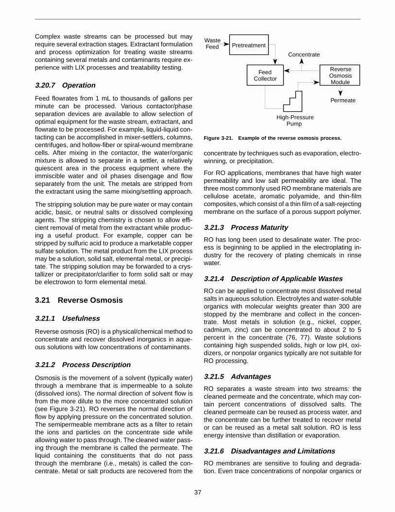
Complex waste streams can be processed but mayrequire several extraction stages. Extractant formulationand process optimization for treating waste streamscontaining several metals and contaminants require ex-perience with LIX processes and treatability testing.
3.20.7 Operation
Feed flowrates from 1 mL to thousands of gallons perminute can be processed. Various contactor/phaseseparation devices are available to allow selection ofoptimal equipment for the waste stream, extractant, andflowrate to be processed. For example, liquid-liquid con-tacting can be accomplished in mixer-settlers, columns,centrifuges, and hollow-fiber or spiral-wound membranecells. After mixing in the contactor, the water/organicmixture is allowed to separate in a settler, a relativelyquiescent area in the process equipment where theimmiscible water and oil phases disengage and flowseparately from the unit. The metals are stripped fromthe extractant using the same mixing/settling approach.
The stripping solution may be pure water or may containacidic, basic, or neutral salts or dissolved complexingagents. The stripping chemistry is chosen to allow effi-cient removal of metal from the extractant while produc-ing a useful product. For example, copper can bestripped by sulfuric acid to produce a marketable coppersulfate solution. The metal product from the LIX processmay be a solution, solid salt, elemental metal, or precipi-tate. The stripping solution may be forwarded to a crys-tallizer or precipitator/clarifier to form solid salt or maybe electrowon to form elemental metal.
3.21 Reverse Osmosis
3.21.1 Usefulness
Reverse osmosis (RO) is a physical/chemical method toconcentrate and recover dissolved inorganics in aque-ous solutions with low concentrations of contaminants.
3.21.2 Process Description
Osmosis is the movement of a solvent (typically water)through a membrane that is impermeable to a solute(dissolved ions). The normal direction of solvent flow isfrom the more dilute to the more concentrated solution(see Figure 3-21). RO reverses the normal direction offlow by applying pressure on the concentrated solution.The semipermeable membrane acts as a filter to retainthe ions and particles on the concentrate side whileallowing water to pass through. The cleaned water pass-ing through the membrane is called the permeate. Theliquid containing the constituents that do not passthrough the membrane (i.e., metals) is called the con-centrate. Metal or salt products are recovered from the
concentrate by techniques such as evaporation, electro-winning, or precipitation.
For RO applications, membranes that have high waterpermeability and low salt permeability are ideal. Thethree most commonly used RO membrane materials arecellulose acetate, aromatic polyamide, and thin-filmcomposites, which consist of a thin film of a salt-rejectingmembrane on the surface of a porous support polymer.
3.21.3 Process Maturity
RO has long been used to desalinate water. The proc-ess is beginning to be applied in the electroplating in-dustry for the recovery of plating chemicals in rinsewater.
3.21.4 Description of Applicable Wastes
RO can be applied to concentrate most dissolved metalsalts in aqueous solution. Electrolytes and water-solubleorganics with molecular weights greater than 300 arestopped by the membrane and collect in the concen-trate. Most metals in solution (e.g., nickel, copper,cadmium, zinc) can be concentrated to about 2 to 5percent in the concentrate (76, 77). Waste solutionscontaining high suspended solids, high or low pH, oxi-dizers, or nonpolar organics typically are not suitable forRO processing.
3.21.5 Advantages
RO separates a waste stream into two streams: thecleaned permeate and the concentrate, which may con-tain percent concentrations of dissolved salts. Thecleaned permeate can be reused as process water, andthe concentrate can be further treated to recover metalor can be reused as a metal salt solution. RO is lessenergy intensive than distillation or evaporation.
3.21.6 Disadvantages and Limitations
RO membranes are sensitive to fouling and degrada-tion. Even trace concentrations of nonpolar organics or
Concentrate
Permeate
High-PressurePump
WasteFeed
ReverseOsmosisModule
FeedCollector
Pretreatment
Figure 3-21. Example of the reverse osmosis process.
37

moderate to high levels of suspended solids will foul themembranes. Pretreatment can be used to condition thewaste and reduce fouling problems. Extreme pH condi-tions or oxidizers in the waste solution will degrade themembrane (70).
The ability of the membrane to retain dissolved contami-nants is based on molecule size, weight, and electricalcharge, as well as variations of maximum pore size ofthe membrane; therefore retention may be difficult topredict. RO seldom exhibits “absolute” retention (77).
Evaporation produces more concentrated solutions thandoes RO, which is frequently used to preconcentratewaste streams prior to evaporation.
3.21.7 Operation
Performance of the RO system typically is measured bythree parameters: flux, product recovery, and rejection(78). Flux is the flowrate of permeate per unit area ofmembrane measured as liters per square meter (gallonsper square foot) per day. The major factors influencingthe sustainable flux are the physical and chemical sta-bility of the membrane, fouling rate, and flow limits dueto concentration polarization at the membrane.
Product recovery is the ratio of permeate flow to feedflow and typically is controlled by adjusting the flowrateof the reject stream leaving the RO module. Low productrecoveries result in a low concentration of the metals.As product recovery increases, the metals concentra-tion of the concentrate increases, requiring an increasein pressure from the pump to overcome the osmoticpressure.
Rejection measures the degree to which the metal isprevented from passing through the membrane. Rejec-tion increases with the ionic size and charge of themetals in the feed. Rejection is dependent on the oper-ating pressure, conversion, and feed concentration.Typically, metals removal by RO is greater than 95percent.
3.22 Diffusion Dialysis
3.22.1 Usefulness
Diffusion dialysis is a method to recover acids or basesfor reuse by processing waste aqueous solutions thatcontain acids or bases contaminated with dissolvedmetals and organics, particulate and colloidal matter,and other dissolved or suspended nonionic species.
3.22.2 Process Description
Diffusion dialysis is a simple ionic exchange membranetechnology that uses the concentration gradient as thedriving force to achieve separation of acids or basesfrom waste solutions (see Figure 3-22). Anion exchange
membranes allow the passage of anions only (e.g., Cl,NO3, F, SO4
2−), and cation exchange membranes allowthe passage of cations only (e.g., Na+, NH4
+). Themembranes are impermeable to nonionic species, par-ticulates, colloids, and even organics. The only excep-tion to the impermeability is the passage of hydrogen(H+) and hydroxyl (OH) ions. Because of their small sizeand high mobility, hydrogen ions can pass through ananion exchange membrane that is impermeable to allother positively charged ions, and hydroxyl ions canpass through a cation exchange membrane. The processunit consists of a stack of anion exchange membranes(in acid recovery) or cation exchange membranes (inbase recovery) with spaces between them (79).
3.22.3 Process Maturity
Large-scale diffusion dialysis units (760 to 7,600 L/day[200 to 2,000 gal/day]) for acid or base recovery areavailable and in commercial operation at several sites inthe United States. Several vendors also supply small-scale (38 to 380 L/day [10 to 100 gal/day]) portableunits. The units are modular, and increases in size orflowrate involve adding membranes to the stack.
3.22.4 Description of Applicable Wastes
The most frequent uses of diffusion dialysis have beento recover acid values from spent pickling liquor in steelplants and spent aluminum anodizing baths, to recovermineral acids from battery waste, and to recover caustic
ProductAcid
A
W
P
Anionic Selective Membrane
Cationic Metal
Aqueous Wastestream
Product Acid
KEY
M+
A
A
A
A
DepletedWaste
WasteAcid
Water
M+
M+
M+
W
W
W
P
PAcid
Acid
Figure 3-22. Example of a diffusion dialysis cell.
38

from chemical milling waste. Diffusion dialysis can re-cover acids or bases from solutions containing particu-lates, colloidal suspensions, dissolved metals, anddissolved organics. Dissolved organics are either non-ionic or positively charged in acidic waste streams ornegatively charged in basic waste streams, and they arerejected by the anion exchange or cation exchangemembranes used in the recovery of acids and bases,respectively. The acid or base concentration in the feedwaste streams can be as high as 30 percent by weightin diffusion dialysis. Waste solutions containing mixedacids (e.g., HF and nitric acid) also can be recovered.
3.22.5 Advantages
Diffusion dialysis is a low-pressure, low-temperatureprocess that does not require the addition of treatmentchemicals. Power is needed to run the pumps, a minimalrequirement. Skid-mounted, modular, portable diffusiondialysis units are available, allowing convenient applica-tion on site. The modular design provides the ability toadjust capacity as needed. The process can handleacidic or base streams in small, drummed batches or asa continuous stream from a process. Operating costsare minimal.
3.22.6 Disadvantages and Limitations
Diffusion dialysis uses water in quantities equal to thevolume of the waste stream. The product stream con-taining the acid or base values must be used on site orshipped for sale. The capital costs are high comparedwith conventional wastewater treatment equipment. Thecapital cost of a small (38 L/day [100 gal/day]) diffusiondialysis unit is $25,000. Membranes are susceptible toscaling and biological fouling. The overall process eco-nomics depend on the usable membrane life (80).
3.22.7 Operation
The aqueous waste stream and water are fed counter-currently into alternate compartments in the membranestack. Under the influence of the concentration gradient,the acid values (consisting of H+ ions and anions) fromthe waste stream pass through the anion exchangemembrane and migrate to the water stream, forming theproduct acid. The acid-depleted waste stream contain-ing the dissolved metals, particulates, and other non-ionic species (e.g., organics) is sent for disposal. Therecovered acid is either sold or used in the plant. Theacid recovery rate typically is 90 to 99 percent. Theflowrates of the waste stream and water stream usuallyare comparable. Similar flowrates and countercurrentflow assure minor or no dilution of acid concentration inthe product stream relative to the feed waste stream.The unit for base recovery is similar to that for the acidsystem except that cation exchange membranes are
used and alkali values from the waste stream migrateacross the membrane to the product stream.
3.23 Electrodialysis
3.23.1 Usefulness
Electrodialysis (ED) is a method to recover acids orbases for reuse by processing aqueous waste streams,or to concentrate and recover selected ions from aque-ous waste streams containing other dissolved or sus-pended contaminants.
3.23.2 Process Description
In ED, ions in solution are selectively transported acrossion exchange membranes under the influence of anapplied direct-current field (see Figure 3-23). The ionexchange membranes are either anion selective (i.e.,permeable to anions such as Cl−, SO4
2−) or cation se-lective (i.e., permeable to positive ions). The membraneitself acts as a barrier to the solution, to suspendedparticles, and to other dissolved nonionic species. AnED unit consists of hundreds of alternating anion andcation exchange membranes with spacers betweenthem. Water and the feed containing dissolved ions andother contaminants are introduced into adjacent com-partments in alternating fashion. Under the imposedpolarity, the anions and cations from the feed migrate inopposite directions and concentrate in the two adjacentwater-filled compartments. Because of the alternatingarrangement of cation and anion membranes, the ions
Cathode
Anode +
Feed
AnodeRinse
Concentrate
ProductWater
CathodeRinse
A
+
Anionic Selective Membrane
Cationic Selective Membrane
Cation
Anion
KEY
C
A
A
A
C
C
C
_
_
_
_
_
+
+
+
Figure 3-23. Example of an electrodialysis cell.
39

pass through the first membrane they encounter but areblocked by the next membrane because of their charge.The combination of migration due to the electric field andthe arrangement of ion-selective membranes allowsions to concentrate in the water-filled compartments. EDunits are capable of concentration factors of 10 or more.The concentrate and the diluate (feed solution depletedof most of its ions) are collected and reused (79).
3.23.3 Process Maturity
ED units are used in commercial operations to recovermetal plating baths (80). Small units (38 to 190 L/day[10 to 50 gal/day]) are used in small plating job shops,and large units (380 to 3,800 L/day [100 to 1,000 gal/day])are used in larger applications such as at aircraft main-tenance depots.
3.23.4 Description of Applicable Wastes
ED is used to recover caustic from spent chemical mill-ing solutions, metal values from plating rinse water, andacid from spent etchants and pickling liquors (5). EDunits separate chemical values from solutions con-taining particulates and colloid suspensions. The acid orbase concentrations in the feed and concentratestreams can be as high as 25 percent by weight inelectrodialysis.
2.23.5 Advantages
The concentrate stream volume is small relative to thefeed stream volume (by a factor of 10 or more), resultingin the recovery of chemical values in a concentratedform. Skid-mounted, modular, portable electrodialysisunits are available that allow convenient application onsite. The modular design provides the ability to adjustcapacity as needed.
3.23.6 Disadvantages and Limitations
Electrodialysis requires a source of power (10 to 200 kW)to effect the separation. The diluate (feed depleted of itschemical values) may not meet primary treatment stand-ards and may require additional cleanup prior to dis-posal. The capital costs are high compared with thosefor conventional wastewater treatment equipment. Themembranes are susceptible to scaling and biologicalfouling. The overall process economics depend on theusable membrane life (80).
3.23.7 Operation
Waste stream (feed) and water are fed into alternatecompartments in the ED stack. The dissolved ions (ac-ids, bases, or metal salts) migrate from the waste streamunder the influence of the electric field and concentratein the water stream. The water stream flowrate is sub-stantially smaller than the waste stream flowrate. The
concentrate containing the recovered chemical valuesis collected. The ion-depleted waste stream may bereused as rinsewater or discarded, depending on theapplication.
3.24 Evaporation
3.24.1 Usefulness
Evaporation is a thermal method to concentrate andrecover dissolved inorganics in aqueous materials withlow concentrations of contaminants.
3.24.2 Process Description
Evaporation takes place when a liquid is heated andconverts to vapor, with the liquid boiled away to leave aconcentrated salt solution or slurry (see Figure 3-24).Evaporation processes may be used to recover thevaporized liquid, to form a concentrated salt solution forreuse, or to preconcentrate a salt solution for additionalprocessing for recovery of a metal or salt (81).
3.24.3 Process Maturity
Evaporation is used commercially to reduce the volumeof aqueous solutions produced by a wide variety ofprocesses (80). Applications for reuse or recovery ofvaluable products are less common but have been com-mercialized to recover dragout from plating baths, re-cover contaminated acids, and produce ferric chloridefrom steel pickling baths (82).
3.24.4 Description of Applicable Wastes
Evaporation is best suited to processing waters contain-ing moderate starting concentrations of dissolved salts.Waste streams containing more than about 4,000 mg/L(230 grains/gal) of metal usually can be efficientlyevaporated to as high as 20 percent solids (76).
Evaporation is used to treat a variety of wastewaterstreams containing dissolved metal salt contaminants.For example, plating rinse wastes can be concentrated
Concentrate
Cleaned Water
WasteFeed
To Off-GasTreatment
Vaporizer
Heater
Condenser
Figure 3-24. Example of the evaporation process.
40

by evaporation. The evaporated water is reused forrinsing, and the concentrate is returned to the plating bath.
Concentration by evaporation is more difficult for wastescontaining foam-stabilizing impurities such as surfac-tants, fine particulates, or proteins; salts that have re-duced solubility at elevated temperature (e.g., calciumcarbonate); compounds that decompose at elevatedtemperature; and high-suspended-solids concentra-tions.
3.24.5 Advantages
Evaporation concentrates dilute solutions of solublesalts. Volume reductions of 80 to 99 percent are pos-sible, depending on the initial salt and suspended solidsconcentration and the salt solubility. The concentratedsolution may be reused directly but usually is furthertreated by cementation, precipitation, electrowinning, orother processes to produce useable salts, metals, orbrines. Evaporated water can be condensed and reusedas onsite process water (5).
3.24.6 Disadvantages and Limitations
Evaporation systems generally have high capital costsand require both a significant energy input and a systemto collect and treat off-gas. Suspended solids, oil, andgrease cause foaming, which increases the difficulty ofprocess operations.
3.24.7 Operation
Evaporation processes require sufficient heat energy tovaporize the liquid waste matrix. Evaporation usually iscarried out either by boiling heat transfer or flash evapo-ration. In boiling heat transfer, steam, hot oil, or anotherheat transfer source is applied to transfer heat througha coil or vessel wall into the waste material. Boiling ofthe waste occurs at the heated wall. In flash evapora-tion, the waste is heated under pressure and then flowsby pumping or natural circulation to a vessel at lowerpressure, where boiling occurs. Common examples ofevaporators using boiling heat transfer are rising film,falling film, and wiped film evaporators. Flash evapora-tion is accomplished in forced or natural circulationevaporators.
During the past decade, the use of atmospheric evapo-rators has increased for recovery of plating chemicals.The atmospheric evaporator contacts an airstream withheated solution. The air humidifies and removes water,concentrating the solution. The atmospheric evapora-tors have lower processing rates than conventionalevaporators but use simpler, less expensive equipmentand are suitable for onsite processing of small volumesof aqueous waste.
3.25 Mercury Bioreduction
3.25.1 Usefulness
Mercury bioreduction is a biochemical method to re-cover mercury metal for reuse by processing mercury-contaminated soils, sludges, sediments, and liquids.
3.25.2 Process Description
Bacterially mediated reduction of ionic mercury to mer-cury metal plays an important role in the geochemicalcycle of mercury in the environment (83, 84). Two orga-nisms, Pseudomonas putida (85) and Thiobacillus ferro-oxidans (86), have been tested for their application tothe reduction and recovery of mercury wastewater. Bio-logical activity can reduce mercury salts to metal (seeFigure 3-25). Elemental mercury metal is a dense liquidwith a relatively high vapor pressure, so low-energyseparation methods can recover the mercury after bio-reduction. In most concepts, the bioreduced mercurymetal is removed from the waste matrix by air flow, thencaptured on activated carbon. Mercury metal is thenrecovered by retorting (Section 3.34). When the wastematrix viscosity is low, mercury metal may be recovereddirectly by gravity separation (Section 3.33).
3.25.3 Process Maturity
Bioreduction of mercury salts to metal is being exploredin the laboratory (87). There is no field experience withthe technology.
3.25.4 Description of Applicable Wastes
The bioreduction process is potentially applicable toremoval of mercury from solid or liquid wastes.
3.25.5 Advantages
Bioreduction allows mercury recovery to occur withoutapplication of heat or use of potentially hazardouschemical leaching agents.
Air
Mercury-Contaminated
Water Off-Gas andMercury Vapor
EffluentSampling
Air
BIOMASS
Figure 3-25. System to study geochemical cycling of mercury(adapted from Barkay et al. [83]).
41

3.25.6 Disadvantages and Limitations
Organisms can tolerate only low concentrations of mer-cury. Biological reactions typically proceed at slowerrates than analogous chemical reactions, so longer resi-dence times and larger reactor volumes are needed.
3.25.7 Operation
Biological detoxification of mercury-contaminated wastecould be carried out in a well-mixed aerobic reactorsystem. The reaction is an enzyme-catalyzed reductionof ionic mercury to mercury metal. The elemental mer-cury could be removed from the reaction media by airstripping or gravimetric separation. If air stripping isused, mercury is captured on activated carbon, whichcan be treated by retorting for mercury recovery.
3.26 Amalgamation
3.26.1 Usefulness
Amalgamation is a chemical method to recover mercuryfor reuse by processing solutions of mercury salts inwater.
3.26.2 Process Description
Amalgamation depends on the ability of mercury to formlow-melting-point alloys with a wide variety of metals. Ametal, typically zinc, that is thermodynamically able todecompose mercury compounds is contacted with asolution of mercury salt (see Figure 3-26). A chemicalreaction occurs, reducing the mercury ions to mercurymetal, which then combines with the zinc to form a solidalloy. The zinc/mercury amalgam is treated by retortingto recover the mercury (88).
3.26.3 Process Maturity
In the past, mercury amalgamation was used to extractgold and silver from ores by formation of an amalgam.Mercury was retorted from the amalgam for reuse in theprocess, leaving gold or silver metal (89). Amalgamationcurrently is not applied for removal or recovery of mer-cury from wastewaters.
3.26.4 Description of Applicable Wastes
Amalgamation of mercury with zinc recovers mercuryfrom salts or elemental mercury in water solution.
3.26.5 Advantages
Amalgamation recovers elemental mercury, producesan easily recoverable solid, and gives rapid reactionrates if a large surface area of sacrificial metal is avail-able.
3.26.6 Disadvantages and Limitations
Amalgamation does not reduce the total metal contentof the wastewater. The solution must be clear and freeof oil, grease, and emulsified or suspended matter.Noble metals in solution are precipitated by cementationand increase zinc consumption.
3.26.7 Operation
In practice, finely divided zinc is mixed with the mercury-containing solution. Good agitation is needed to ensurecontact between the zinc particles and the solution.Sufficient excess zinc is required to ensure that all mer-cury ions are reduced and that a mercury/zinc amalgamforms. The amalgam is separated from the treated waterand retorted to recover mercury metal.
3.27 Cementation
3.27.1 Usefulness
Cementation is an electrochemical method to recovermetals for reuse by processing from aqueous solutions.
3.27.2 Process Description
Cementation is the precipitation of a metal in solutionfrom its salts by a displacement reaction using another,more electropositive metal (see Figure 3-27). For ex-ample, copper or silver can be displaced from solutionby elemental iron.
3.27.3 Process Maturity
Cementation is a mature process used for the produc-tion of copper metal. Cementation has also been appliedfor the removal of copper from acid mine waters (80).
Mercury-Contaminated
Water
TreatedEffluent
ZincParticulate
Mercury-ZincAmalgam
to Retorting
Figure 3-26. Example of a mercury amalgamation cell.
42

3.27.4 Description of Applicable Wastes
Cementation is applicable to recovery of dissolved noblemetals from aqueous solutions. Use of aluminum todisplace more-noble metals was tested and indicatedthe potential for removal of many salts of copper, tin andlead. The test solutions contained about 200 mg/L(12 grains/gal) of metal at a pH of 2.5. Recovery ofcopper complexed by ethylenediaminetetraacetic acid(EDTA) was only 51 percent. No copper was displacedfrom the nitrate solutions, apparently due to the acidicpH (90).
3.27.5 Advantages
Cementation recovers elemental metal, produces aneasily filterable precipitate, and gives rapid reactionrates if a large surface area of sacrificial metal isavailable.
3.27.6 Disadvantages and Limitations
Cementation does not reduce the total metal content ofthe wastewater. The more-noble metal that precipitatesis replaced by dissolution of the less-noble metal. Eco-nomic recovery requires an inexpensive source of less-noble metal in fine particulate form.
These disadvantages can be offset by combining ce-mentation with electrowinning. For example, zinc can beused to electrochemically precipitate (cement) lead,copper, and cadmium from solution. The zinc is thenrecovered by electrowinning (Section 3.28).
3.27.7 Operation
A solution of noble metal (e.g., copper) is contacted witha less-noble metal (e.g., zinc or iron). Thorough agitationduring treatment is critical for effective removal (90). Thenoble metal is displaced from the solution as elemental
metal and is collected by filtration. Automobile shredderscrap is a common source of iron for commercial coppercementation.
3.28 Electrowinning
3.28.1 Usefulness
Electrowinning is an electrochemical method to recoverelemental metal for reuse by processing moderate- tohigh-concentration aqueous solutions.
3.28.2 Process Description
Electrowinning uses direct current (DC) electricity ap-plied to electrodes immersed in an aqueous solution toconvert dissolved metal ions to elemental metal (seeFigure 3-28). Positively charged metal ions migrate tothe negative electrode, where the metal ions are re-duced to elemental metal. The metal plates out on theelectrode for subsequent collection and reuse.
3.28.3 Process Maturity
Electrowinning applies principles and equipment similarto those of commercial electroplating but differs in itsgoal: to recover metals rather than form a decorative orprotective coating. In electrowinning, the metal coatingappearance is unimportant, so thicker coats can beallowed to accumulate. Electrowinning is applied com-mercially in the mineral refining industry and for recoveryof metals from spent electroplating baths.
Less-NobleMetal
Particulate
PrecipitatedMore-Noble
Metal
Metal-Contaminated
Water
TreatedEffluent
˜Fe + Cu(SO) = Fe(SO) + Cu0 4 4 0
Figure 3-27. Example of a cementation cell.
Negative ElectrodeCollecting
Plated MetalPositiveElectrode
DCPowerSupply
Figure 3-28. Example of an electrowinning cell.
43

3.28.4 Description of Applicable Wastes
Electrowinning is most effective for recovery of more-noble metals. Metals with a high electrode potential areeasily reduced and deposited on the cathode. Gold andsilver are ideal candidates, but cadmium, chromium,copper, lead, nickel, tin, and zinc also can be recoveredusing a higher voltage (80, 91). Electrowinning will re-move metals from solutions containing chelating agents,which are difficult to recover by physical or chemicalprocesses (70).
3.28.5 Advantages
Electrowinning recovers metals from aqueous solutionswithout requiring further processing and without gener-ating any metal-containing sludge or process residuals.The residual metal in the liquid effluent from a well-designed and well-operated electrowinning cell is signifi-cantly reduced, but ion exchange polishing of the efflu-ent may be required (70, 92).
3.28.6 Disadvantages and Limitations
Electrowinning is most efficient when applied to concen-trated solutions. For example, ion exchange resins canbe used to remove metals, which are then concentratedin the solution used to regenerate the resin (Section3.19). The regeneration solution is treated by electro-winning to recover the metal.
Electrowinning typically does not remove metals in so-lution to acceptable limits for discharge. Ion exchangeoften is used to further reduce the metal concentrationin a solution after electrowinning. The regenerationchemicals from the ion exchange process also aretreated in the electrowinning cell to complete metal re-covery (93). Cementation (Section 3.27) also is used topolish water treated by electrowinning (91).
Electrowinning is best applied to solutions with onemetal contaminant. Selecting the electrode potential cancontrol the type of metal deposited on the cathode. Forexample, more-noble metals are removed at lower ap-plied voltage. Noble metals can be recovered frommixed-metal baths, but base metals are more difficult toseparate. Electrowinning from mixed-metal systems in-creases the complexity of operation.
Adverse reactions can occur in an electrochemical celldepending on the impurities present in the waste (80).An acid mist is generated over the electrowinning cell.The acid off-gas must be collected and treated (70).
3.28.7 Operation
An electrowinning metal recovery system requires anelectroplating tank, a direct current power source, elec-trodes, and support equipment. Solution flow should bemaintained past the cathode by either rotating the cath-
ode or moving the solution by pumping or air agitation(94). The cathode is often a thin sheet of the metal beingrecovered and may be reticulated to increase electrodesurface area. High electrode surface area decreases thelocal current density, increases current efficiency, andreduces electrode corrosion. When a cathode is loadedwith recovered metal, it is removed and replaced. Themetal-coated cathode is sold for the metal value. Flattitanium cathodes also are used. With titanium cath-odes, the electrowon metal is stripped off in thin sheets.Less expensive cathode designs such as metal-coatedplastic sheet or mesh may be used, but the value of therecovered metal is reduced by embedded plastic. Theanode is made of a conductive and corrosion-resistantmaterial such as stainless steel or carbon (5).
Electrowinning from dilute solutions is less efficient dueto low ion diffusion rates. The efficiency of electrowin-ning metals from dilute solutions can be improved byheating the solution, by agitation, and by using a largecathode area. Salt may need to be added to maintainminimal conductivity in the solution being treated (82).
3.29 Chemical Leaching
3.29.1 Usefulness
Leaching is a chemical method to recover metals ormetal compounds for reuse by processing solids andsludges containing low to moderate concentrations ofcontaminants. A description of desirable properties for feedmaterials to chemical leaching is given in Section 4.8.
3.29.2 Process Description
Chemical leaching transfers metals from a solid matrixinto the leaching solution (see Figure 3-29). Solutionprocessing methods are then used to regenerate theleachant and recover a useful metal or salt. The combi-nation of chemical leaching and leachant regenerationis known as hydrometallurgical processing. Hydromet-allurgical processing typically includes one or more ofthe following four steps:
• Dissolution of the desired metal
• Purification and/or concentration of the metal
• Recovery of the metal or a metal salt
• Regeneration of the leaching solution
3.29.3 Process Maturity
Chemical leaching is developed at the commercial scalefor recovery of metals from various sludges, catalysts,and other solid matrices. Several RCRA-permitted facili-ties are available for processing leachable metal char-acteristic wastes and listed wastewater treatmentsludges (95). Pilot-scale tests have demonstrated lead
44

recovery from contaminated soil at Superfund sites byacid extraction followed by regeneration of the extrac-tion solution (96-98).
3.29.4 Description of Applicable Wastes
Chemical leaching and hydrometallurgical processingcan be applied to a variety of solid and sludge wastes.Wastes containing a high concentration of one metal inone valence state are preferred (99). Waste streamsprocessed include wastewater treatment sludges (e.g.,plating operations [F006], metal finishing, and electroniccircuit board etching), baghouse dust, and spent cata-lyst. The metals reclaimed include chromium, nickel,copper, zinc, lead, cadmium, tin, cobalt, vanadium, tita-nium, molybdenum, gold, silver, palladium, and platinum.
Chemical leaching for mercury recovery is a new andgrowing technology area. Several chemical leaching for-mulations have been developed to remove mercuryfrom contaminated soils (87). Processes to recover leadby acid leaching followed by electrowinning are beingdeveloped (100, 101).
Products are often metal salts. For example, hydroxideplating or etching sludge can be converted to metal saltssuch as copper chloride, copper ammonium chloride, ornickel carbonate (102). For catalysts, metals and sub-strate materials can be converted by leaching andsolution processing into products such as nickel-copper-
cobalt concentrate, alumina trihydrate, chromium oxide,molybdenum trioxide, and vanadium pentoxide (103).
3.29.5 Advantages
Hydrometallurgical processes recover metal contami-nants to produce metal or metal salts directly or upgradelow-concentration materials to allow metal recovery insecondary smelters. For some wastes, the process alsomay recover the matrix in a useful form, leaving noresidue requiring disposal. Hydrometallurgy usually ismore efficient than pyrometallurgy if the metal concen-tration is low (from the percent range down to parts permillion). Hydrometallurgical processing can require less-capital-intensive facilities than pyrometallurgical proc-essing, but economies of scale still apply.
3.29.6 Disadvantages and Limitations
The chemical leaching operation produces large vol-umes of leach solution. These solutions typically areregenerated for reuse to leach the next batch of mate-rial. Reuse is required both to recover the economicvalue of the leaching chemicals and to avoid the envi-ronmental impacts associated with treatment and dis-charge of waste solutions.
Leaching of soils with a high clay content leaves fine,suspended particulate in the leachant. This fine particu-late complicates further processing of the leachant andis difficult to remove.
Soil
Grizzly
Wet ClassificationSand
Trommel — Screw
Leaching Mixer
Clarifier
MetalRecovery
Dewater
RemixSoil
pHAdjust
CleanOversize
CleanRock,Gravel
CleanSand
Silt,Clay
Silt, Clay
Leachant
ClarifiedLeachant
RegeneratedLeachant
Silt, Clay
Leachant
CleanSilt, Clay
RecoveredMetal
CleanSoil
Figure 3-29. Example of the chemical leaching process (adapted from U.S. EPA [24]).
45

3.29.7 Operation
Hydrometallurgy uses aqueous and/or organic solventsto dissolve a metal from the solid matrix. (For moreinformation on liquid ion exchange/solvent extraction ofmetals, see Section 3.20.) The dissolution process iscalled leaching. The leaching solution is chosen, basedon the types of metals and compounds present in thematrix being treated, to maximize recovery of valuablemetals while minimizing dissolution of unwanted speciesin the matrix. The leaching chemistry often relies onformation of metal complexes. However, a newly devel-oping branch of hydrometallurgy, called supercritical ex-traction, relies on the unusual solvent power of water,CO2, and organics above the critical pressure and tem-perature to affect the selective dissolution.
Once the metal is in solution, further processing typicallyis required to remove impurities, increase the metalconcentration, or both. The full range of classical solu-tion processing methods is available for upgradingthe leach solution. The most commonly used methodsare precipitation (Section 3.18), liquid ion exchange(Section 3.20), and conventional resin ion exchange(Section 3.19).
The concentrated and purified metal-containing solutiontypically requires further treatment to produce a market-able product. In some cases, the metal salt or complexis reduced to native metal. Reduction to metal can beaccomplished by electrowinning or by reducing the met-al using a reducing gas such as hydrogen. Alternatively,the end product of the hydrometallurgical process maybe a metal salt. Chemical processing converts the com-pound in solution to a more marketable oxide or saltform.
3.30 Vitrification
3.30.1 Usefulness
Conversion to a ceramic product is a thermal method toform useful products from slags and sludges with lowconcentrations of metal contaminants alone or mixedwith organics. Ceramic products can range from high-value materials such as abrasives or architectural stoneto low-value materials such as aggregate. Some char-acteristics of high- and low-value ceramic products areoutlined in Sections 4.9 and 4.12, respectively.
3.30.2 Process Description
This technology uses heating to promote oxidation, sin-tering, and melting, thus transforming a broad spectrumof wastes into a glasslike or rocklike material. The melt-ing energy can be derived from the oxidation of materi-als in the feed supplemented by combustion of fossilfuels or electrical heating. The process typically collectsparticulate in the off-gas system and returns the particu-
late to the melter feed so secondary waste generationis minimized. The discharged solid can be formed intoceramic products (see Figure 3-30).
3.30.3 Process Maturity
Vitrification/sintering to form a stable glasslike or rock-like solid is a commercially available technology (105).
3.30.4 Description of Applicable Wastes
Waste materials amenable to treatment include filtercakes, foundry sand, ash, and sludge. The processtreats inorganic wastes containing cadmium, chromium,cobalt, copper, lead, nickel, vanadium, or zinc. Exam-ples of suitable wastes include sludge from wastewatertreatment, electric arc furnace off-gas treatment resi-dues, and baghouse dust (104).
The presence of volatile metals in the waste complicatesvitrification processing due to production of metal vaporsin the off-gas. Metals such as mercury or beryllium thatvolatilize under process conditions may not be amen-able to treatment. Wastes containing arsenic requiresome combination of pretreatment and special process-ing conditions and off-gas treatment systems to mini-mize arsenic volatilization.
Selected waste streams can be converted into high-value ceramic products such as abrasives, decorativearchitectural stone, or refractory. Wastes suitable forthese processes typically are hydroxide sludge fromtreatment of plating or etching baths containing a singlemetal contaminant. The process has been applied com-mercially to F006 wastes (106).
Processes have been demonstrated for thermal conver-sion of a variety of silicate matrices containing metal andorganic contaminants into intermediate-value ceramicproducts. For example, fly ash (107), incinerator ash(108), iron foundry slag (109), and petroleum-contami-nated soils (110, 111) have been used for the manufac-ture of bricks. In addition, spent abrasive blasting mediahave been used to replace sand in the manufacture ofbricks and mortar.
Low-value construction aggregate and stone can beproduced from a variety of waste materials. Examplesinclude concrete aggregate produced from fly ash (112,113) or fill material produced by vitrification of metal-containing wastes.
3.30.5 Advantages
The discharged product is a chemically durable materialthat typically passes the Toxicity Characteristic LeachingProcedure (TCLP) test as nonhazardous. The processprovides volume reduction (40 percent for soils togreater than 99 percent for combustibles). The high
46

operating temperature destroys organic contaminants inthe waste (70).
3.30.6 Disadvantages and Limitations
The thermal conversion process is capital and energyintensive. Revenue is unlikely to equal processing costs,even for waste streams that form a high-value product.The main economic advantage is avoided disposalcosts.
Thermal processing generates large volumes of off-gasthat must be controlled and cleaned. Volatile metals inthe waste, particularly arsenic, beryllium, or mercury,complicate processing.
3.30.7 Operation
Ceramic products may be formed by either sintering ormelting. In both processes, prepared waste material isheated to form the ceramic. Most thermal treatmentprocesses require feed material to be within a narrowparticle size range. Size reduction, pelletization, or bothprocesses usually are needed to obtain the requiredsize.
In sintering, the waste is prepared by mixing with clayor other silicate and possibly water and additives. Theresulting mix is pressed or extruded to form pellets,which are treated at high temperature but below thebulk melting temperature. Particles join to form a solidceramic piece.
Vitrification processes also require feed preparation.Chemical additions and mixing may be used to promoteoxidation-reduction reactions that improve the proper-ties and stability of the final product. Silica sources such
as sand or clay also may be needed. Vitrification proc-esses operate by heating the pretreated waste to melt-ing temperatures. The molten, treated waste flow exitsfrom the melter into a waste forming or quenching step.The melt can be formed in a sand-coated mold orquenched in a water bath, depending on the type ofproduct required.
Gases released from the thermal treatment unit areprocessed through an emission control system. Particu-lates may form due to carryover, metal fuming, or anionfuming. The particulates are removed by knockoutboxes, scrubbers, and/or venturi separators. Particu-lates are separated from the scrubbing fluid by filtrationand are returned to the treatment system. Acid gases,such as sulfur dioxide from sulfates, are removed byscrubbing with sodium hydroxide.
3.31 Pyrometallurgical Metal Recovery
3.31.1 Usefulness
Pyrometallurgical processing is a thermal method torecover metals or metal compounds for reuse by proc-essing solids and sludges with percent concentrationsof metal contaminants. A description of desirable prop-erties for feed material to a pyrometallurgical metal re-covery process is given in Section 4.7. A case study ofprocessing Superfund site wastes in a secondary leadsmelter is described in Section 5.4.
3.31.2 Process Description
Pyrometallurgy is a broad term covering techniques forprocessing metals at elevated temperature. Processingat elevated temperature increases the rate of reaction
Mixer
Filter
Kiln
Air PollutionControl System
Metals-Bearing Waste
Solids
Off-Gas
ScrubberWater
Flue Gas
Product Exit
Chemicals Silicates
Filtered Water
Figure 3-30. Example of the vitrification process (adapted from U.S. Air Force [103]).
47

and reduces the reactor volume per unit output (seeFigure 3-31). Elevated temperature also may benefitthe reaction equilibrium. Pyrometallurgy offers a well-developed and powerful collection of tools for recoveryof metals from waste materials. Three general types ofpyrometallurgical processes are in use:
• Pretreatment of material as preparation for furtherprocessing.
• Treatment of material to convert metal compounds toelemental metal or matte and to reject undesirablecomponents.
• Subsequent treatment to upgrade the metals ormatte.
These operations may be used singly, in sequence, orin combination with physical, hydrometallurgical, bio-logical, or electrometallurgical processing depending onthe types of material processed. The three types ofpyrometallurgical processes generally use differentequipment and approaches.
3.31.3 Process Maturity
Pyrometallurgical processing is developed at the com-mercial scale for recovery of cadmium, lead, and zincfrom K061 (RCRA waste code for Electric Arc Furnaceemission control dust/sludge) and a variety of metal-containing silicate and sludge wastes.
3.31.4 Description of Applicable Wastes
Pyrometallurgical processing typically is used to processlarge volumes of solid or low-moisture sludge containingpercent levels of metals. Processing capacity is availablefor a variety of metal leachability characteristic wastes,F006-listed waste, and other metal-containing soils,slags, dusts, sludges, ashes, or catalysts. The types ofmaterials processed include wastes from electroplating,electropolishing, metal finishing, brass and steel foun-dries, galvanizing, zinc diecasting, nickel-cadmium andiron-nickel batteries, chromium-magnesite refractories,waste magnesium powders and machinings, and potliner from aluminum smelters (114-119).
Some facilities may accept wastes containing tracequantities of metals if the matrix is a good source ofsilica or alkali for flux or a carbon source for metalreduction. Processing ash from incineration of municipalwastewater treatment sludge provides silica as a fluxand allows recovery of trace quantities of gold and silver.Pyrometallurgical processors also may accept usedfoundry sand for metals and silica, lime residues fromboiler cleaning or dolomitic refractories for metals andalkali, or carbon brick and coke fines for carbon.
3.31.5 Advantages
Pyrometallurgy is an extractive treatment approach thatcan recover metals or metal salts for reuse. The highoperating temperature destroys organic contaminants inthe waste (70). The volume of slag residual resulting
OXIDATION SMELTING REDUCTION SMELTING
AirCombustion Gases(Cd, As, Hg, Pb*)
Liquid Slag(Ba, Cr, Zn, Pb)
Liquid Metal(Ag)Heat
Fluxes
*If Temperature Is Sufficiently High (1,400-1600 C),o
Pb Will Volatilize as PbO
FluxesReduction Gases(Hg, Cd, As, Zn)
Liquid Slag(Ba, Cr)
Liquid Metals(Ag, Pb, Cr*)
HeatReductant
(Coal, Oil, Gas)
*Chromium Will Distribute Between Metal and Slag
Figure 3-31. Examples of pyrometallurgical processes.
48

from the process typically is smaller than the initial wastevolume. In most cases, the hazardous metal concentra-tion in the slag is low and the slag is leach resistant, soit may be reused as a low-value aggregate product.
3.31.6 Disadvantages and Limitations
Pyrometallurgical processing is applicable only to spe-cific types of wastes. Success depends both on thetypes and concentrations of metals present and thephysical and chemical form of the matrix.
The process is capital and energy intensive. Processingcan be profitable or break even when the waste containsa high concentration of valuable metal or can be proc-essed as a small addition to an existing feedstream. Forother waste types, pyrometallurgical processing is costly.
Pyrometallurgical processing generates large volumesof off-gas that must be controlled and cleaned. Volatilemetals in the waste, particularly arsenic, complicateprocessing.
3.31.7 Operation
Oxidation is often used as a pyrometallurgical pretreat-ment to convert sulfide materials to oxides. Normallyoxidation is carried out as a gas-solid phase contact ofair passing over fine particulate material in a multihearthor fluidized bed reactor. Pretreatment also is used toselectively metallize the feed for subsequent leaching.
Pyrometallurgical processing to convert metal com-pounds to metal usually requires a reducing agent, flux-ing agents to facilitate melting and slag off impurities,and a heat source. The fluid mass often is called a melt,although the operating temperature, while quite high,often is below the melting points of the refractorycompounds being processed. The fluid forms as a low-melting-point material due to the chemistry of the melt.An acceptable melting point is achieved by addition offluxing agents, such as calcium oxide, or by appropriateblending of feedstocks.
Carbon is the most commonly used reducing agent forbase metal compounds. The carbon typically reacts toproduce carbon monoxide and carbon dioxide whileforming free metal or matte. Combustion of the carbonalso can provide the required heat input. Feedstocks,such as sulfides or organic-laden wastes, react exother-mically, thus providing some heat input as well.
The most common fluxing agents in mineral smelting aresilica and limestone. The flux is added along with thereducing agent to produce a molten mass. A wide varietyof molten salts, molten metals, or other fluxing systemsare used for special processing situations.
Separation of the metal from the undesirable wastecomponents typically is accomplished by physical actionbased on phase separations. As the metal salts react
with the reducing agent to form metal or matte, thenonmetallic portions of the ore combine with the flux toform a slag. Volatile metals such as zinc or cadmiumvaporize and are collected by condensation or oxidationfrom the off-gas, usually as oxides due to combustion ofmetal fume in the flue. Dense, nonvolatile metals can beseparated from the less dense silicate slag by gravitydraining of metallics from the bottom of the reactionvessel. Slag oxides are tapped from a more elevatedtaphole.
Pyrometallurgical processes for final purification (refin-ing) usually take the form of selective volatilization,drossing, or liquation. In some cases, ores consist ofless-volatile metals such as lead and iron mixed withvolatile metals such as zinc, cadmium, or arsenic. Forother metal systems, chemical reactions are needed toform volatile species to allow separation of product met-als and impurities.
3.32 Cement Raw Materials
3.32.1 Usefulness
Use of inorganic wastes as raw material in cementmanufacture is a thermal method to recover inorganics,mainly aluminum, iron, or silica, from solid materials withlow concentrations of contaminants. Burning of mainlyorganic-containing materials in a cement kiln for heatingvalue is discussed in Section 3.3. A description of desirableproperties for cement raw materials is given in Section4.10. A case study using spent sand blasting media forcement raw materials is described in Section 5.2.
3.32.2 Process Description
In this process, waste materials are fed to a cement kilnas a substitute for raw materials such as limestone,shale, clay, or sand. The primary constituents of cementare silica, calcium, aluminum, and iron. Inside the ce-ment kiln, the raw material substitutes undergo chemicaland physical reactions at temperatures that progres-sively reach 1,480°C (2,700°F) to form cement clinker(see Figure 3-32). Inorganic contaminants are boundinto the lattice structure of the cement crystals.
3.32.3 Process Maturity
Nonhazardous silicate and aluminate wastes are usedas raw material substitutes in Portland cement manufac-ture on a commercial scale. Application to wastes con-taining RCRA metals may be possible, but commercialapplication is limited by the requirements of the Boilerand Industrial Furnace regulations.
3.32.4 Description of Applicable Wastes
The primary raw materials of interest are silica, calcium,aluminum, and iron. Good candidates for raw materials
49

substitution typically contain 95 percent or more of theseconstituents. Examples of acceptable feed materials in-clude the following sources:
Alumina sources:
• Catalysts
• Ceramics and refractories
• Coal ash
• Adsorbents for gases and vapors
• Aluminum potliner waste
Calcium sources:
• Lime sludges
Iron sources:
• Foundry baghouse residuals
• Iron mill scale
Silica sources:
• Abrasives
• Ceramics
• Clay filters and sludges
• Foundry sand
• Sand blast media
• Water filtration media
3.32.5 Advantages
Cement kilns provide high operating temperatures andlong residence times to maximize the immobilization ofmetal contaminants into the cement mineral structure.The high-alkali reserve of the cement clinker reacts toform alkali chlorides (sodium, potassium, calcium) thatprevent the evolution of acidic vapors in the off-gas. Thechloride content must be limited, however, to avoid va-por production and to prevent soluble chlorides fromdegrading the setting rate of the cement product (119).
3.32.6 Disadvantages and Limitations
Both combustion to heat the raw materials and decom-position reactions during formation of cement clinkergenerate large volumes of off-gas that must be controlledand cleaned.
3.32.7 Operation
Raw material burning typically is done in a rotary kiln.The kiln rotates around an inclined axis. The raw mate-rials enter the raised end of the kiln and travel down theincline to the lower end. The kiln is heated by combus-tion of coal, gas, or oil in the kiln. As the raw materialsmove through the inclined, rotating kiln, they heat totemperatures in the area of 1,480°C (2,700°F). The hightemperature causes physical and chemical changes,such as (8):
• Partial fusion of the feed materials
• Evaporation of free water
• Evolution of carbon dioxide from carbonates
During burning, lime combines with silica, alumina, andiron to form the desired cement compounds. The heat-ing results in the cement clinker. Clinker consists ofgranular solids with sizes ranging from fine sand towalnut size. The clinker is rapidly cooled, mixed withadditives such as gypsum, and ground to a fine powderto produce the final cement product.
Portland cement product is produced by heating mix-tures containing lime, silica, alumina, and iron oxide toform clinker, which is then ground. About 3 to 5 percentof calcium sulfate, usually as gypsum or anhydrite, isadded during grinding of the clinker. The gypsum aidsthe grinding process and helps control the curing rate ofthe cement product (120). The gypsum is intermixedduring grinding of the clinker. The main constituents ofPortland cement typically are tricalcium silicate, dical-cium silicate, tricalcium aluminate, and tetracalcium alu-minoferrite.
Clay, Shale,and Limestone
Fuel
Clinker Cooler
Cooling Fans
AirRotary Kiln
To Gypsum Additionand Grinding
To Off-GasTreatment
Figure 3-32. Example of a cement kiln operation.
50
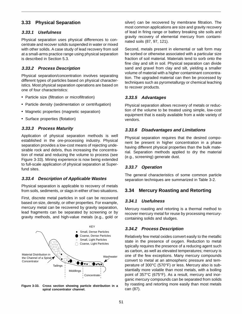
3.33 Physical Separation
3.33.1 Usefulness
Physical separation uses physical differences to con-centrate and recover solids suspended in water or mixedwith other solids. A case study of lead recovery from soilat a small-arms practice range using physical separationis described in Section 5.3.
3.33.2 Process Description
Physical separation/concentration involves separatingdifferent types of particles based on physical character-istics. Most physical separation operations are based onone of four characteristics:
• Particle size (filtration or microfiltration)
• Particle density (sedimentation or centrifugation)
• Magnetic properties (magnetic separation)
• Surface properties (flotation)
3.33.3 Process Maturity
Application of physical separation methods is wellestablished in the ore-processing industry. Physicalseparation provides a low-cost means of rejecting unde-sirable rock and debris, thus increasing the concentra-tion of metal and reducing the volume to process (seeFigure 3-33). Mining experience is now being extendedto full-scale application of physical separation at Super-fund sites.
3.33.4 Description of Applicable Wastes
Physical separation is applicable to recovery of metalsfrom soils, sediments, or slags in either of two situations.
First, discrete metal particles in soil can be recoveredbased on size, density, or other properties. For example,mercury metal can be recovered by gravity separation,lead fragments can be separated by screening or bygravity methods, and high-value metals (e.g., gold or
silver) can be recovered by membrane filtration. Themost common applications are size and gravity recoveryof lead in firing range or battery breaking site soils andgravity recovery of elemental mercury from contami-nated soils (87, 97, 121).
Second, metals present in elemental or salt form maybe sorbed or otherwise associated with a particular sizefraction of soil material. Materials tend to sorb onto thefine clay and silt in soil. Physical separation can dividesand and gravel from clay and silt, yielding a smallervolume of material with a higher contaminant concentra-tion. The upgraded material can then be processed bytechniques such as pyrometallurgy or chemical leachingto recover products.
3.33.5 Advantages
Physical separation allows recovery of metals or reduc-tion of the volume to be treated using simple, low-costequipment that is easily available from a wide variety ofvendors.
3.33.6 Disadvantages and Limitations
Physical separation requires that the desired compo-nent be present in higher concentration in a phasehaving different physical properties than the bulk mate-rial. Separation methods applied to dry the material(e.g., screening) generate dust.
3.33.7 Operation
The general characteristics of some common particleseparation techniques are summarized in Table 3-2.
3.34 Mercury Roasting and Retorting
3.34.1 Usefulness
Mercury roasting and retorting is a thermal method torecover mercury metal for reuse by processing mercury-containing solids and sludges.
3.34.2 Process Description
Relatively few metal oxides convert easily to the metallicstate in the presence of oxygen. Reduction to metaltypically requires the presence of a reducing agent suchas carbon, as well as elevated temperatures; mercury isone of the few exceptions. Many mercury compoundsconvert to metal at an atmospheric pressure and tem-perature of 300°C (570°F) or less. Mercury also is sub-stantially more volatile than most metals, with a boilingpoint of 357°C (675°F). As a result, mercury and inor-ganic mercury compounds can be separated from solidsby roasting and retorting more easily than most metalscan (87).
Small, Dense ParticlesCoarse, Dense ParticlesSmall, Light ParticlesCoarse, Light Particles
Tailings
Middlings
Concentrate
WashwaterMaterial Distribution inthe Channel of a SpiralConcentrator
KEY
Figure 3-33. Cross section showing particle distribution in aspiral concentrator channel.
51
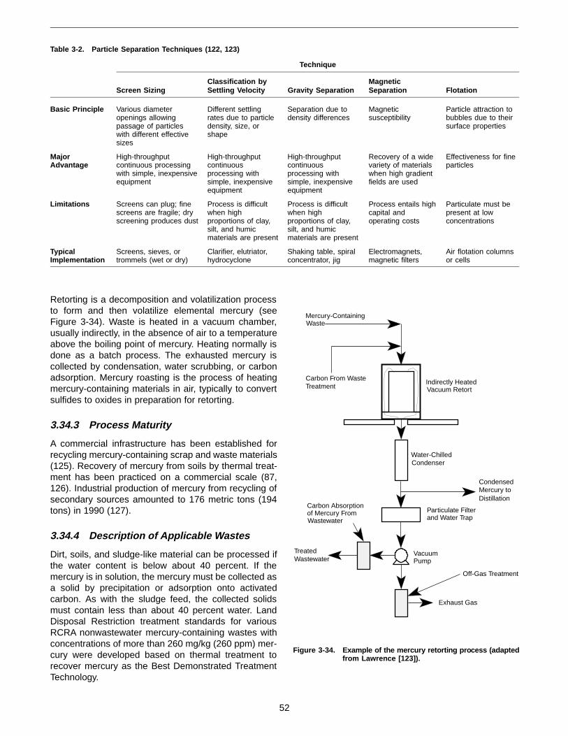
Retorting is a decomposition and volatilization processto form and then volatilize elemental mercury (seeFigure 3-34). Waste is heated in a vacuum chamber,usually indirectly, in the absence of air to a temperatureabove the boiling point of mercury. Heating normally isdone as a batch process. The exhausted mercury iscollected by condensation, water scrubbing, or carbonadsorption. Mercury roasting is the process of heatingmercury-containing materials in air, typically to convertsulfides to oxides in preparation for retorting.
3.34.3 Process Maturity
A commercial infrastructure has been established forrecycling mercury-containing scrap and waste materials(125). Recovery of mercury from soils by thermal treat-ment has been practiced on a commercial scale (87,126). Industrial production of mercury from recycling ofsecondary sources amounted to 176 metric tons (194tons) in 1990 (127).
3.34.4 Description of Applicable Wastes
Dirt, soils, and sludge-like material can be processed ifthe water content is below about 40 percent. If themercury is in solution, the mercury must be collected asa solid by precipitation or adsorption onto activatedcarbon. As with the sludge feed, the collected solidsmust contain less than about 40 percent water. LandDisposal Restriction treatment standards for variousRCRA nonwastewater mercury-containing wastes withconcentrations of more than 260 mg/kg (260 ppm) mer-cury were developed based on thermal treatment torecover mercury as the Best Demonstrated TreatmentTechnology.
Table 3-2. Particle Separation Techniques (122, 123)
Technique
Screen SizingClassification bySettling Velocity Gravity Separation
MagneticSeparation Flotation
Basic Principle Various diameteropenings allowingpassage of particleswith different effectivesizes
Different settlingrates due to particledensity, size, orshape
Separation due todensity differences
Magneticsusceptibility
Particle attraction tobubbles due to theirsurface properties
MajorAdvantage
High-throughputcontinuous processingwith simple, inexpensiveequipment
High-throughputcontinuousprocessing withsimple, inexpensiveequipment
High-throughputcontinuousprocessing withsimple, inexpensiveequipment
Recovery of a widevariety of materialswhen high gradientfields are used
Effectiveness for fineparticles
Limitations Screens can plug; finescreens are fragile; dryscreening produces dust
Process is difficultwhen highproportions of clay,silt, and humicmaterials are present
Process is difficultwhen highproportions of clay,silt, and humicmaterials are present
Process entails highcapital andoperating costs
Particulate must bepresent at lowconcentrations
TypicalImplementation
Screens, sieves, ortrommels (wet or dry)
Clarifier, elutriator,hydrocyclone
Shaking table, spiralconcentrator, jig
Electromagnets,magnetic filters
Air flotation columnsor cells
Indirectly HeatedVacuum Retort
Water-ChilledCondenser
Particulate Filterand Water Trap
VacuumPump
CondensedMercury toDistillation
Carbon Absorptionof Mercury FromWastewater
Mercury-ContainingWaste
Carbon From WasteTreatment
Exhaust Gas
TreatedWastewater
Off-Gas Treatment
Figure 3-34. Example of the mercury retorting pro cess (adaptedfrom Lawrence [123]).
52

3.34.5 Advantages
Roasting and retorting each provide an effective meansto recover mercury from a variety of mercury-containingsolids. Both fixed facilities and transportable units areavailable (128).
3.34.6 Disadvantages and Limitations
Roasting and retorting generate an off-gas stream thatmust be controlled and cleaned. Volatile metals in thewaste, particularly arsenic, complicate processing.
3.34.7 Operation
In the retorting process, solids contaminated with mer-cury are placed in a vacuum-tight chamber. Followingclosure of the chamber, a vacuum is established andheat is applied. Operating the retort under vacuum helpscollect and control mercury emissions from the process.The materials in the chamber are subjected to tempera-tures in excess of 700°C (1,300°F). Mercury is vapor-ized from the material, withdrawn, and collected. Themercury can be further purified by distillation. Themercury-free solids are transported to other facilities forrecovery of other metals, if possible.
Typical feed materials include metal and glass materi-als. Most plastics can be processed, but PVC and otherhalogen-containing materials must be minimized due tothe potential for generating corrosive or volatile materi-als during heating in the retort. Volatile or reactive met-als such as lithium, arsenic, and thallium also are notallowed in the process (124).
3.35 Mercury Distillation
3.35.1 Usefulness
Mercury distillation is a thermal method to recover high-purity mercury metal for reuse by processing slightlycontaminated liquid elemental mercury.
3.35.2 Process Description
Mercury distillation relies on mercury’s relatively lowboiling point to allow purification of slightly contaminatedliquid mercury to very high levels of purity. Mercury andvolatile impurities boil off in a vacuum retort, leavingnonvolatile impurities in the retort. The mercury vaporsare then distilled to concentrate volatile impurities in amercury heel to produce high-purity mercury (see Figure3-35). Multiple passes through retorting and distillation canproduce 99.9999 percent or higher purity mercury (125).
3.35.3 Process Maturity
Distillation is commercially available for final cleanup ofslightly contaminated liquid mercury metal.
3.35.4 Description of Applicable Wastes
Feed to a mercury distillation process typically is free-flowing mercury liquid showing a shiny surface and novisible water, glass fragments, or other solids. Physicalseparation may be used to remove solids to allow distil-lation of the mercury. Wastes containing lead, cadmium,or arsenic usually are unacceptable for distillation.
Typical waste sources are mercury metal liberated fromsolid by retorting, electronic scrap, and impure, usedmercury.
3.35.5 Advantages
Distillation can be applied to clean mercury recoveredby roasting or retorting (Section 3.34).
3.35.6 Disadvantages and Limitations
The process generates an off-gas stream that must becontrolled and cleaned. Volatile metals in the waste,particularly arsenic, complicate processing.
3.35.7 Operation
Mercury distillation typically is carried out in small batchvacuum systems. Vacuum distillation reduces the re-quired operating temperatures and helps collect andcontrol mercury emissions from the process. The usualprocessing capacity for a batch is 208 L (55 gal). Higherpurity mercury is produced by redistillation and/or wash-ing. Specially designed distillation operations can pro-duce 99.99999 percent (“7 nines”) pure mercury withquadruple distillation. The more common approach istriple distillation followed by washing the mercury withdilute nitric acid to yield 99.9999 percent (“6 nines”) puremercury.
3.36 Decontamination and Disassembly
3.36.1 Usefulness
Decontamination and disassembly uses mechanicaland chemical methods to clean and disassemble proc-ess equipment and structures to allow recovery of met-als or inorganic materials for reuse. A source for
MercuryFeed
PurifiedMercuryProduct
Mercury Distillation Units
Waste
Figure 3-35. Example of the mercury distillation process(adapted from Lawrence [123]).
53
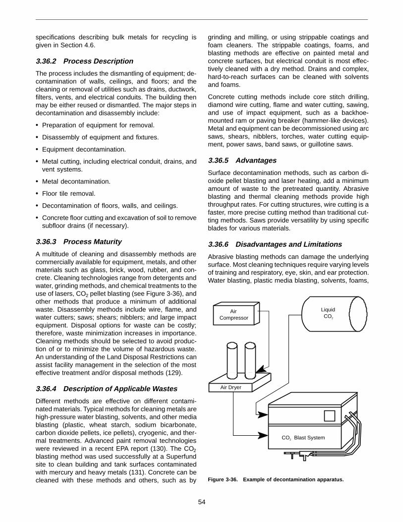
specifications describing bulk metals for recycling isgiven in Section 4.6.
3.36.2 Process Description
The process includes the dismantling of equipment; de-contamination of walls, ceilings, and floors; and thecleaning or removal of utilities such as drains, ductwork,filters, vents, and electrical conduits. The building thenmay be either reused or dismantled. The major steps indecontamination and disassembly include:
• Preparation of equipment for removal.
• Disassembly of equipment and fixtures.
• Equipment decontamination.
• Metal cutting, including electrical conduit, drains, andvent systems.
• Metal decontamination.
• Floor tile removal.
• Decontamination of floors, walls, and ceilings.
• Concrete floor cutting and excavation of soil to removesubfloor drains (if necessary).
3.36.3 Process Maturity
A multitude of cleaning and disassembly methods arecommercially available for equipment, metals, and othermaterials such as glass, brick, wood, rubber, and con-crete. Cleaning technologies range from detergents andwater, grinding methods, and chemical treatments to theuse of lasers, CO2 pellet blasting (see Figure 3-36), andother methods that produce a minimum of additionalwaste. Disassembly methods include wire, flame, andwater cutters; saws; shears; nibblers; and large impactequipment. Disposal options for waste can be costly;therefore, waste minimization increases in importance.Cleaning methods should be selected to avoid produc-tion of or to minimize the volume of hazardous waste.An understanding of the Land Disposal Restrictions canassist facility management in the selection of the mosteffective treatment and/or disposal methods (129).
3.36.4 Description of Applicable Wastes
Different methods are effective on different contami-nated materials. Typical methods for cleaning metals arehigh-pressure water blasting, solvents, and other mediablasting (plastic, wheat starch, sodium bicarbonate,carbon dioxide pellets, ice pellets), cryogenic, and ther-mal treatments. Advanced paint removal technologieswere reviewed in a recent EPA report (130). The CO2
blasting method was used successfully at a Superfundsite to clean building and tank surfaces contaminatedwith mercury and heavy metals (131). Concrete can becleaned with these methods and others, such as by
grinding and milling, or using strippable coatings andfoam cleaners. The strippable coatings, foams, andblasting methods are effective on painted metal andconcrete surfaces, but electrical conduit is most effec-tively cleaned with a dry method. Drains and complex,hard-to-reach surfaces can be cleaned with solventsand foams.
Concrete cutting methods include core stitch drilling,diamond wire cutting, flame and water cutting, sawing,and use of impact equipment, such as a backhoe-mounted ram or paving breaker (hammer-like devices).Metal and equipment can be decommissioned using arcsaws, shears, nibblers, torches, water cutting equip-ment, power saws, band saws, or guillotine saws.
3.36.5 Advantages
Surface decontamination methods, such as carbon di-oxide pellet blasting and laser heating, add a minimumamount of waste to the pretreated quantity. Abrasiveblasting and thermal cleaning methods provide highthroughput rates. For cutting structures, wire cutting is afaster, more precise cutting method than traditional cut-ting methods. Saws provide versatility by using specificblades for various materials.
3.36.6 Disadvantages and Limitations
Abrasive blasting methods can damage the underlyingsurface. Most cleaning techniques require varying levelsof training and respiratory, eye, skin, and ear protection.Water blasting, plastic media blasting, solvents, foams,
LiquidCO2
AirCompressor
Air Dryer
CO2 Blast System
Figure 3-36. Example of decontamination apparatus.
54

and detergents all add to the pretreated quantity ofwaste. Most cutting techniques also require dust andcontamination control before, during, and/or after cuttingoperations. Some equipment, such as large saws, wirecutters, shears, and coring machines, can be heavy andcumbersome to use.
Decontamination and disassembly processing can re-veal asbestos in many forms. Asbestos-containing ma-terial was used as insulation, in siding and shingles, andin laboratory hood and equipment linings (transite). Sitesurveys should include identification and charac-terization of asbestos-containing materials and appro-priate planning for decontamination and disassemblyoperations.
3.36.7 Operation
The types of equipment and materials and the timerequired for decontamination vary depending on whichmethod is used. Solvents may be used in a self-con-tained unit or may be circulated through pipes anddrains. Cleaning times range from a few minutes to afew days. Blasting equipment generally consists of apumping mechanism, vacuum mechanism, and possiblya treatment system for recycling the blasting media.Cleaning times range from 0.5 to 35 m2/hr (5 to 350 ft2/hr).
Cutting and grinding techniques may require pretreat-ment or a tent for dust control, as well as stabilization ofsurrounding material. A vacuum system also may beused for cleanup and containment of the waste. Thetime required for operation depends on the material andthe equipment chosen, and can range from 0.1 to1.8 m2/hr (1 to 20 ft2/hr).
3.37 Recycling Transformers and Ballasts
3.37.1 Usefulness
Electrical equipment containing PCB-dielectric oils canbe processed to destroy the PCBs, allowing continueduse of the device, or can be disassembled to recoverthe metals in the device. A source for specificationsdescribing bulk metals for recycling is given in Section4.6.
3.37.2 Process Description
Recycling of electrical devices using PCB-containingdielectric oils such as transformers (see Figure 3-37)involves a combination of mechanical disassembly andchemical and thermal treatment to recover metals and,in some cases, the dielectric oil. The recycling of trans-formers and ballasts is a concern because older electri-cal equipment commonly used oils containing PCBs.Recycling a transformer involves three major steps: test-ing the oil for PCB content, removing the oil from thetransformer, and disassembling the transformer. Once
the transformer is disassembled, its components can bedecontaminated, and salvageable materials can be re-cycled (132, 133).
3.37.3 Process Maturity
Since the initial PCB Marking and Disposal Rule in1978, technologies have emerged to improve the effi-ciency of cleaning and recycling PCB oils and transform-ers with less risk to the public. Methods to dechlorinatethe transformer oils were in place by the early 1980s.Technologies have emerged for cleaning the oil using amobile unit while the transformer is operating (134). Fortransformers that are replaced with newer, more efficientmodels, an estimated 90 to 95 percent of the trans-former metal is recyclable (135).
3.37.4 Description of Applicable Wastes
Recovery of metals and dielectric oils is applicable to avariety of electric equipment, mainly transformers andballast inductors. The components of the transformersinclude oil, tanks, cores, coils, valves, insulating materi-als, bushings, and other fittings, such as gauges andswitches.
3.37.5 Advantages
Replacing or decontaminating transformers containingPCB fluids can reduce the costs associated with fluidtesting, regulatory inspection recordkeeping, and poten-tial spill cleanup. Metals can be salvaged from obsoletetransformers. In some cases, PCB-containing dielectricoil may be dechlorinated and reused. Dechlorinateddielectric oil that is unsuitable for reuse can be treatedby incineration. Incineration of transformer fluids andinsulation materials from PCB transformers destroysthe material and the PCBs, and the use of a metalsreclamation furnace can yield even cleaner metals for
Model of a 100-kvatransformer.Approximate actual size is71 in.
Model No.Z100-1994A
Figure 3-37. Example of a transformer
55
recycling. Surface contamination of metal and ceramiccomponents can sometimes be removed with the use ofsolvents so that the materials can be reused.
3.37.6 Disadvantages and Limitations
Thermal destruction of PCBs can create products ofincomplete combustion, such as dioxins or dibenzo-furans. Solvents used for surface cleaning of metal partsare distilled for reuse, but a PCB residue remains thatis treated by incineration (136). Discarded materialsmust be carefully monitored so that Toxic SubstancesControl Act (TSCA) disposal requirements are not vio-lated and no contamination of the disposal facility oc-curs. Materials disposed of in a landfill also continue tocarry a liability, i.e., they are still the responsibility of thegenerator (137).
3.37.7 Operation
The actual decommissioning process starts by testingthe filling oil. When handling PCB-contaminated materi-als, the recycling contractor implements measures toprevent, contain, and clean up spills. The oil is tested todetermine the level of personal protection clothing andequipment required.
Once the oil is properly drained from the transformer, thetransformer is disassembled. The transformer body,core steel, copper, aluminum, brass, and other metalcomponents of the disassembled transformer are thenaccessible for recycling. Some processors clean themetal parts with solvent and transfer the metals to asmelter for recycling. Other processors use onsite incin-erators, ovens, or furnaces to burn unwanted insulatingmaterials and the adhering PCB contaminants from thetransformer internals. Onsite incineration results in de-contaminated metal scrap but can produce products ofincomplete combustion from trace residual PCBs.
The dielectric oil typically is treated by a chemicaldechlorination process. The dechlorinated oil may beeither reused or destroyed by incineration.
Decontaminated materials with no commercial value,such as ceramic bushings, are sent to a landfill fordisposal.
3.38 References
When an NTIS number is cited in a reference, thatdocument is available from:
National Technical Information Service 5285 Port Royal Road Springfield, VA 22161 703-487-4650
1. Rogers, T.N., and G. Brant. 1989. Distillation. In:Freeman, H.M., ed. Standard handbook of hazard-ous waste treatment and disposal. New York, NY:McGraw-Hill. pp. 6.23-6.38.
2. California Department of Health Services. 1990.Alternative technologies for the minimization ofhazardous waste. California Department of HealthServices, Toxic Substances Control Program(July).
3. U.S. EPA. 1989. Project summary: Field measure-ments of full-scale hazardous waste treatmentfacilities—organic solvent wastes. EPA/600/S2-88/073. Cincinnati, OH.
4. Hertz, D.W. 1989. Reduction of solvent and arse-nic wastes in the electronics industry. HazardousMaterials Management Conference and Exhibi-tion. Oakland, CA: Association of Bay Area Gov-ernments. pp. 374-387.
5. Stanczyk, T.F. 1992. Converting wastes into reus-able resources with economic value. Presented atthe Government Institutes Pollution PreventionPractical Management and Compliance StrategiesTraining Course, Syracuse, NY (September).
6. Stoltz, S.C., and J.B. Kitte, eds. 1992. Steam: Itsgeneration and use, 40th ed. New York, NY: Bab-cock & Wilcox Company.
7. Waste Tech News. 1994. Wood recycling plantunder construction. Waste Tech News 6(10):4.
8. Gossman, D. 1992. The reuse of petroleum andpetrochemical waste in cement kilns. Environ.Prog. 11(1):1-6.
9. U.S. EPA. 1993. Report to Congress on cementkiln dust, Vol. II: Methods and findings. EPA/530/R-94/001 (NTIS PB94-126 919). Washington, DC.
10. Bouse, E.F., Jr., and J.W. Kamas. 1988. Updateon waste as kiln fuel. Rock Products 91:43-47.
11. Bouse, E.F., Jr., and J.W. Kamas. 1988. Waste askiln fuel, part II. Rock Products 91:59-64.
12. Blumenthal, M.H. 1993. Tires. In: Lund, H.F., ed.The McGraw-Hill recycling handbook. New York,NY: McGraw-Hill.
13. PCA. 1992. An analysis of selected trace metalsin cement and kiln dust. Skokie, IL: Portland Ce-ment Association.
14. U.S. EPA. 1988. Decision criteria for recoveringCERCLA wastes (draft report), Contract No. 68-01-7090, WA B-17, Task Order W61517.C6.
56

15. Hooper, W.B., and L.J. Jacobs, Jr. 1988. Decanta-tion. In: Schweitzer, P.A., ed. Handbook of separa-tion techniques for chemical engineers. New York,NY: McGraw-Hill.
16. Morgan, T.A., S.D. Richards, and W. Dimoplon.1992. Hydrocarbon recovery from an oil refinerypitch pit. Proceedings of National Conference:Minimization and Recycling of Industrial and Haz-ardous Waste ’92. Rockville, MD: Hazardous Ma-terials Control Resources Institute.
17. U.S. EPA. 1991. Engineering bulletin: Thermaldesorption treatment. EPA/540/2-91/008. Wash-ington, DC.
18. U.S. EPA. 1993. Innovative treatment technolo-gies: Semiannual status report, 5th ed. EPA/542/R-93/003. Washington, DC.
19. U.S. EPA. 1993. Low temperature thermal processfor pesticides and other organic compounds. In:Tech Trends. EPA/542/N-93/007. Washington, DC.
20. U.S. EPA. 1993. Guidelines for making environ-mentally-sound decisions in the Superfund reme-dial process. Chicago, IL: Region V WasteManagement Division (May).
21. Ayen, R.J., and C. Swanstrom. 1991. Develop-ment of a transportable thermal separation proc-ess. Environ. Prog. 10(3):175-181.
22. Just, S.R., and K.J. Stockwell. 1993. Comparisonof the effectiveness of emerging in situ technolo-gies and traditional ex situ treatment of solvent-contaminated soils. Emerging technologies inhazardous waste management III. AmericanChemical Society Symposium Series 518. Wash-ington, DC: American Chemical Society.
23. U.S. EPA. 1992. Low temperature treatment (LT3)technology. EPA/540/AR-92/019. Washington, DC.
24. U.S. EPA. 1993. Superfund innovative technologyevaluation program: Technology profiles, 6th ed.EPA/540/R-93/526. Washington, DC.
25. U.S. EPA. 1993. Applications analysis report:Resource conservation company B.E.S.T. solventextraction technology. EPA/540/AR-92/079. Wash-ington, DC.
26. U.S. EPA. 1990. Applications analysis report: CFsystems organics extraction process, New Bed-ford Harbor, MA. EPA/540/A5-90/002. Washing-ton, DC.
27. U.S. EPA. 1990. Engineering bulletin: Solvent ex-traction treatment. EPA/540/2-90/013. Washing-ton, DC, and Cincinnati, OH.
28. U.S. EPA. 1991. Innovative treatment technolo-gies: Overview and guide to information sources.EPA/540/9-91/002. Washington, DC.
29. Wisconsin Department of Natural Resources.1993. Foundry waste beneficial reuse study.PUBL-SW-181-93. Madison, WI: Wisconsin De-partment of Natural Resources.
30. Ahmed, I. 1993. Use of waste materials in high-way construction. Park Ridge, NJ: Noyes DataCorporation.
31. Testa, S.M., and D.L. Patton. 1993. Soil remedia-tion via environmentally processed asphalt. In:Hager, J.P., B.J. Hansen, J.F. Pusateri, W.P. Imrie,and V. Ramachandran, eds. Extraction and proc-essing for the treatment and minimization ofwastes. Warrendale, PA: The Minerals, Metals,and Materials Society. pp. 461-485.
32. U.S. EPA. 1990. Handbook on in situ treatment ofhazardous waste-contaminated soils. EPA/540/2-90/002. Cincinnati, OH.
33. U.S. EPA. 1991. Engineering bulletin: In situ soilvapor extraction treatment. EPA/540/2-91/006.Washington, DC, and Cincinnati, OH.
34. U.S. EPA. 1991. Reference handbook: Soil vaporextraction technology. EPA/540/2-91/003. Edison,NJ.
35. U.S. EPA. 1993. Engineering forum issue: Consid-erations in deciding to treat contaminated unsatu-rated soils in situ. EPA/540/S-94/500. Washington,DC, and Cincinnati, OH.
36. Cohen, R.M., J.W. Mercer, and J. Matthews. 1993.DNAPL site evaluation. Boca Raton, FL: C.K.Smoley.
37. Superfund Week. 1993. Lead is washed from soilat TCAAP site. Superfund Week 7(44):5.
38. Villaume, J.F., P.C. Lowe, and D.F. Unites. 1983.Recovery of coal gasification wastes: An innova-tive approach. Proceedings of the National WaterWell Association Third National Symposium onAquifer Restoration and Ground-water Monitoring.Worthington, OH: Water Well Journal PublishingCompany.
39. Heist, J.A. 1989. Freeze crystallization. In: Free-man, H.M., ed. Standard handbook of hazardouswaste treatment and disposal. New York, NY:McGraw-Hill. pp. 6.133-6.143.
40. Chowdhury, J. 1988. CPI warm up to freeze con-centration. Chem. Eng. 95:24-31.
57

41. Singh, G. 1988. Crystallization from solutions. In:Schweitzer, P.A., ed. Handbook of separation tech-niques for chemical engineers. New York, NY:McGraw-Hill.
42. Hermann, H. 1991. Disposal of explosives fromdemilitarization: A case study with TNT. Presentedat the 22nd International Annual Conference onICT, Karlsruhe, Germany (July).
43. U.S. EPA. 1993. Handbook: Approaches to theremediation of federal facility sites contaminatedwith explosive or radioactive wastes. EPA/625/R-93/013. Washington, DC.
44. Herman, H.L. 1980. Reclamation of energetic ma-terial components from ordnance ammunition. In:Kaye, S.M. Encyclopedia of explosives and relateditems, PATR 2700, Vol. 9. Dover, NJ: U.S. ArmyArmament Research and Development Com-mand. pp. R-146 - R-150.
45. Van Ham, N.H.A. 1991. Environmentally accept-able disposal of ammunition and explosives. Pro-ceedings of the International Annual ConferenceICT, 22nd IACIEQ, Prins Maurits Lab TNO, 2280AA Rijswijk, The Netherlands (December).
46. U.S. Army. 1993. Conventional ammunition demili-tarization master plan. Rock Island, IL: Headquar-ters U.S. Army Armament, Munitions, andChemical Command.
47. Bohn, M.A., and H. Neumann. 1991. Recovery ofpropellant components by high-temperature high-pressure solvolysis. Presented at the 22nd Inter-national Annual Conference on ICT, Karlsruhe,Germany (July).
48. Ember, L. 1991. Cryofracture problems may pre-vent its use in chemical arms disposal. Chem. Eng.News 69(8):19-20.
49. Crosby, W.A., and M.E. Pinco. 1992. More powerto the pop. Eng. Mining J. 193(5):28-31.
50. Torma, S.C., R.B. Rise, and A.E. Torma. 1993.Environmentally safe processing and recycling ofhigh-energy yield materials. In: Hager, J.P.,B.J. Hansen, J.F. Pusateri, W.P. Imrie, andV. Ramachandran, eds. Extraction and processingfor the treatment and minimization of wastes. War-rendale, PA: The Minerals, Metals, and MaterialsSociety. pp. 73-83.
51. HazTech News. 1994. Hydrotreating adapted todestruction of propellants, chlorinated wastes.HazTech News 9(10):74.
52. Hegberg, B.A., G.R. Brenniman, and W.H. Hallen-beck. 1991. Technologies for recycling post-consumer mixed plastics. Report No. OTT-8.University of Illinois, Center for Solid Waste Man-agement and Research.
53. APC. 1993. Recycled plastic products sourcebook. Washington, DC: American Plastics Council.
54. Andrews, G.D., and P.M. Subramanian. 1991.Emerging technologies in plastic recycling. ACSSymposium Series 513 (June). Washington, DC:American Chemical Society.
55. Bennett, R.A. 1991. New product applications,evaluations, and markets for products manufac-tured from recycled plastics and expansion of na-tional database for plastics recycling. Technicalreport No. 53. Rutgers University, Center for Plas-tics Recycling Research.
56. Reinink, A. 1993. Chemical recycling: Back tofeedstock. Plastics, Rubber, and CompositesProcessing and Applications 20(5):259-264.
57. Rotman, D., and E. Chynoweth. 1994. Plasticsrecycling: Back to fuels and feedstocks. Chem.Week 154:20-23.
58. Pearson, W. 1993. Plastics. In: Lund, H.F., ed. TheMcGraw-Hill recycling handbook. New York, NY:McGraw-Hill.
59. Layman, P.L. 1993. Advances in feedstock recy-cling offer help with plastic waste. Chem. Eng.News 71(40):11-14.
60. Randall, J.C. 1992. Chemical recycling. Mod.Plastics 69(13):54-58.
61. Shelly, S., K. Fouhy, and S. Moore. 1992. Plasticsreborn. Chem. Eng. 99(7):30-35.
62. Randall, J.C. 1993. Chemical recycling. Mod.Plastics 70(12):37-38.
63. Rebeiz, K., D.W. Fowler, and D.R. Paul. 1991.Recycling plastics in polymer concrete for engi-neering application. Polymer Plastics Tech. Eng.30(8):809-825.
64. Swearingen, D.L., N.C. Jackson, and K.W. Ander-son. 1992. Use of recycled materials in highwayconstruction. Report No. WA-RD 252.1. Washing-ton State Department of Transportation.
65. SMCAA. 1992. Recycling of sheet molding com-pounds: The energy/environment picture. AF-184.Washington, DC: Sheet Molding Compound Auto-motive Alliance, Society of the Plastics Industry.
66. Sharp, L.L., and R.O. Ness, Jr. 1993. Thermalrecycling of plastics. Grand Forks, ND: Universityof North Dakota.
58

67. EERC. 1994. Thermal recycling of plastics. GrandForks, ND: University of North Dakota, Energy andEnvironmental Research Center.
68. Curran, P.F., and K.A. Simonsen. 1993. Gasifica-tion of mixed plastic waste. Presented at 8th An-nual Recyclingplas Conference, Washington, DC(June).
69. NEESA. 1993. Precipitation of metals from groundwater. Remedial Action Tech. Data Sheet Docu-ment No. 20.2-051.6. Port Hueneme, CA: NavalEnergy and Environmental Support Activity.
70. U.S. EPA. 1991. Recovery of metals from sludgesand wastewater. EPA/600/2-91/041. Cincinnati, OH.
71. Hickey, T., and D. Stevens. 1990. Recovery ofmetals from water using ion exchange. In: U.S.EPA. Proceedings of Second Forum on InnovativeHazardous Waste Treatment Technologies, Phila-delphia, PA (May). EPA/540/2-90/010.
72. Brown, C.J. 1989. Ion exchange. In: Freeman,H.M., ed. Standard handbook of hazardous wastetreatment and disposal. New York, NY: McGraw-Hill. pp. 6.59-6.75.
73. Ritcey, G.M., and A.W. Ashbrook. 1984. Solventextraction principles and applications to processmetallurgy. New York, NY: Elsevier.
74. ICSECT. 1988. International solvent extractionconference, Moscow, USSR (July). InternationalCommittee for Solvent Extraction Chemistry andTechnology.
75. ICSECT. 1990. International solvent extractionconference, Kyoto, Japan (July). InternationalCommittee for Solvent Extraction Chemistry andTechnology.
76. U.S. EPA. 1993. Project summary: Recyclingnickel electroplating rinse waters by low tem-perature evaporation and reverse osmosis.EPA/600/SR-93/160. Cincinnati, OH.
77. Porter, M.C. 1988. Membrane filtration. In:Schweitzer, P.A., ed. Handbook of separation tech-niques for chemical engineers. New York, NY:McGraw-Hill.
78. MacNeil, J., and D.E. McCoy. 1989. Membraneseparation technologies. In: Freeman, H.M., ed.Standard handbook of hazardous waste treatmentand disposal. New York, NY: McGraw-Hill.pp. 6.91-6.106.
79. Lacey, R.E. 1988. Dialysis and electrodialysis. In:Schweitzer, P.A., ed. Handbook of separation tech-niques for chemical engineers. New York, NY:McGraw-Hill.
80. MSE. 1993.93. Resource recovery project tech-nology characterization interim report. Butte, MT:U.S. Department of Energy Resource RecoveryProject.
81. Delaney B.T., and R.J. Turner. 1989. Evaporation.In: Freeman, H.M., ed. Standard handbook of haz-ardous waste treatment and disposal. New York,NY: McGraw-Hill. pp. 7.77-7.84.
82. Grosse, D.W. 1986. A review of alternative treat-ment processes for metal bearing hazardouswaste streams. J. Poll. Control Assoc. 36:603-614.
83. Barkay, T., R. Turner, E. Saouter, and J. Horn.1992. Mercury biotransformations and their poten-tial for remediation of mercury contamination.Biodegradation 3:147-159.
84. Saouter, E., R. Turner, and T. Barkay. 1994. Mer-cury microbial transformations and their potentialfor the remediation of a mercury-contaminatedsite. In: Means, J.L., and R.E. Hinchee, eds.Emerging technology for bioremediation of metals.Ann Arbor, MI: Lewis Publishers.
85. Horn, J.M., M. Brunke, W.D. Deckwer, and K.N.Timmis. 1992. Development of bacterial strains forthe remediation of mercurial wastes. In: U.S. EPA.Arsenic and Mercury: Workshop on Removal, Re-covery, Treatment, and Disposal. EPA/600/R-92/105. Washington, DC. pp. 106-109.
86. Hansen, C.L., and D.K. Stevens. 1992. Biologicaland physiochemical remediation of mercury-contaminated hazardous waste. In: U.S. EPA.Arsenic and Mercury: Workshop on Removal, Re-covery, Treatment, and Disposal. EPA/600/R-92/105. Washington, DC. pp. 121-125.
87. Stepan, D.J., R.H. Farley, K.R. Henke, H.M. Gust,D.J. Hassett, D.S. Charlton, and C.R. Schmit.1993. Topical report: A review of remediation tech-nologies applicable to mercury contamination atnatural gas industry sites. GRI-93/0099. Chicago,IL: Gas Research Institute; and Morgantown, WV:U.S. Department of Energy.
88. U.S. EPA. 1991. Treatment technology back-ground document. Washington, DC.
89. Veiga, M.M., and J.A. Meech. 1993. Heuristic ap-proach to mercury pollution in the Amazon. In:Hager, J.P., B.J. Hansen, J.F. Pusateri, W.P. Imrie,and V. Ramachandran, eds. Extraction and proc-essing for the treatment and minimization ofwastes. Warrendale, PA: The Minerals, Metals,and Materials Society. pp. 23-38.
90. U.S. EPA. 1990. Project summary: Recovery ofmetals using aluminum displacement. EPA/600/S2-90/032. Cincinnati, OH.
59

91. DeBecker, B., F. Peeters, and P. Duby. 1993. Re-covery of chromium from chromate waste by elec-trowinning from Cr(III) solutions. In: Hager, J.P.,B.J. Hansen, J.F. Pusateri, W.P. Imrie, and V.Ramachandran, eds. Extraction and processingfor the treatment and minimization of wastes. War-rendale, PA: The Minerals, Metals, and MaterialsSociety. pp. 55-72.
92. California Department of Health Services. 1989.Reducing California’s metal-bearing wastestreams. Technical report prepared by Jacobs En-gineering Group, Inc. (August).
93. Hulbert, G., B. Fleet, M. Hess, and J. Kassirer.1989. Technical and economic evaluation of a non-sludge, heavy metal waste reduction system at anaeroscientific corporation, Anaheim, California.Hazardous Materials Management Conferenceand Exhibition. Oakland, CA: Association of BayArea Governments. pp. 330-338.
94. Steward, F.A., and C.G. Ritzert. 1994. Waste mini-mization and recovery technologies. Metal Finish-ing 62nd Guidebook and Directory Issue92(1A):714-716.
95. Ramachandran, V., S.R. Gilbert, R.I. Cardenas,and M. Zwierzykowski. 1993. Recycling metal-bearing hazardous waste. In: Hager, J.P.,B.J. Hansen, J.F. Pusateri, W.P. Imrie, andV. Ramachandran, eds. Extraction and processingfor the treatment and minimization of wastes. War-rendale, PA: The Minerals, Metals, and MaterialsSociety. pp. 131-141.
96. Barth, E.F., M.L. Taylor, J.A. Wentz, and S. Giti-Pour. 1994. Extraction, recovery, and immobi-lization of chromium from contaminated soils.Presented at the 49th Purdue University IndustrialWaste Conference, Lafayette, IN (May).
97. Paff, S.W., and B. Bosilovich. 1993. Remediationof lead-contaminated Superfund sites using sec-ondary lead smelting, soil washing, and othertechnologies. In: Hager, J.P., B.J. Hansen, J.F.Pusateri, W.P. Imrie, and V. Ramachandran, eds.Extraction and processing for the treatment andminimization of wastes. Warrendale, PA: The Min-erals, Metals, and Materials Society. pp. 181-200.
98. Superfund Week. 1993. Mittelhauser wins design.Superfund Week 7(50):3.
99. DuGuay, T. 1993. Reclaim metals to clean up soils.Soils (March 26), pp. 28-33.
100. Lee, A.Y., A.M. Wethington, M.G. Gorman, andV.R. Miller. 1994. Treatment of lead-contaminatedsoil and battery wastes from Superfund sites. Su-perfund XIV. Rockville, MD: Hazardous MaterialsControl Resources Institute.
101. Prengaman, R.D., and H. McDonald. 1990. RSR’sfull scale plant to electrowin lead from batteryscrap. In: Mackey, T.S., and R.D. Prengaman, eds.Lead-zinc ’90. Warrendale, PA: The Minerals, Met-als, and Materials Society.
102. Bishop, J., and M. Melody. 1993. Inorganics treat-ment and recovery. HazMat World 6(2):21-30.
103. Crnojevich, R., E.I. Wiewiorowski, L.R. Tinnin, andA.B. Case. 1990. Recycling chromium-aluminumwastes from aluminum finishing operations. J.Metals 42(10):42-45.
104. U.S. Air Force. 1990. Inorganic waste vitrifica-tion. Tech TIP (newsletter). Dayton, OH: Wright-Patterson Air Force Base, Joint Technology Appli-cations Office.
105. Queneau, P.B., L.D. May, and D.E. Cregar. 1991.Application of slag technology to recycling of solidwastes. Presented at the 1991 Incineration Con-ference, Knoxville, TN (May).
106. Hazardous Waste Consultant. 1990. Electroplat-ing wastes recycled by new vitrification process.Hazardous Waste Consultant 8(4):1-4 - 1-6.
107. Temini, M., A. Ait-Mokhtar, J.P. Camps, and M.Laquerbe. 1991. The use of fly ash in the clayproducts with cement and lime, obtained throughextrusion. In: Goumans, J.J.J.M., H.A. van derSloot, and T.G. Aalbers, eds. Waste materials inconstruction. Studies in environmental science 48.New York, NY: Elsevier. pp. 451-458.
108. Ali, M., T.J. Larsen, L.D. Shen, and W.F. Chang.1992. Cement stabilized incinerator ash for use inmasonry bricks. Cement Industry Solutions toWaste Management: Proceedings of the First In-ternational Conference, Calgary, Alberta, Canada(October). pp. 211-234.
109. Malolepszy, J., W. Brylicki, and J. Deja. 1991. Thegranulated foundry slag as a valuable raw materialin the concrete and lime-sand brick production. In:Goumans, J.J.J.M., H.A. van der Sloot, and T.G.Aalbers, eds. Waste materials in construction.Studies in environmental science 48. New York,NY: Elsevier. pp. 475-478.
110. U.S. EPA. 1992. Potential reuse of petroleum-contaminated soil: A directory of permitted recy-cling facilities. EPA/600/R-92/096. Washington, DC.
60

111. Melody, M. 1993. Pollution prevention notebook:Greening soil. HazMat World 6(10):31.
112. Faase, R.W.M., J.H.J. Manhoudt, and E. Kwint.1991. Power concrete. In: Goumans, J.J.J.M.,H.A. van der Sloot, and T.G. Aalbers, eds. Wastematerials in construction. Studies in environmentalscience 48. New York, NY: Elsevier. pp. 15-432.
113. Wainwright, P.J., and P. Robery. 1991. Productionand properties of sintered incinerator residues asaggregate for concrete. In: Goumans, J.J.J.M.,H.A. van der Sloot, and T.G. Aalbers, eds. Wastematerials in construction. Studies in environmentalscience 48. New York, NY: Elsevier. pp. 425-432.
114. Bounds, C.O., and J.F. Pusateri. 1990. EAF dustprocessing in the gas-fired flame reactor process.In: Mackey, T.S., and R.D. Prengaman, eds. Lead-zinc ’90. The Minerals, Metals, and MaterialsSociety.
115. Hanewald, R.H., W.A. Munson, and D.L.Schweyer. 1992. Processing EAF dusts and othernickel-chromium waste materials pyrometallurgi-cally at INMETCO. Minerals and MetallurgicalProcessing 9(4):169-173.
116. James, S.E., and C.O. Bounds. 1990. Recyclinglead and cadmium, as well as zinc, from EAF dust.In: Mackey, T.S., and R.D. Prengaman, eds. Lead-zinc ’90. Warrendale, PA: The Minerals, Metals,and Materials Society.
117. Krukowski, J. 1993. New hazardous waste solu-tions. Poll. Eng. 25(10):30-32.
118. Queneau, P.B., B.J. Hansen, and D.E. Spiller.1993. Recycling lead and zinc in the United States.The Fourth International Hydrometallurgy Sympo-sium, Salt Lake City, UT (August).
119. Versar Inc. 1988. Decision criteria for recoveringCERCLA wastes. Draft report prepared for U.S.EPA Office of Emergency and Remedial Re-sponse. Springfield, VA: Versar Inc.
120. Collins, R.E., and L. Luckevich. 1992. Portlandcement in resource recovery and waste treatment.Cement Industry Solutions to Waste Management:Proceedings of the First International Conference,Calgary, Alberta, Canada (October). pp. 325-331.
121. Chintis, M. 1992. Recovery of mercury D-009 andU-151 waste from soil using proven physical andgravimetric methods. In: U.S. EPA. Arsenic andMercury: Workshop on Removal, Recovery, Treat-ment, and Disposal. EPA/600/R-92/105. Washing-ton, DC.
122. Perry, R.H., and C.H. Chilton. 1984. Chemicalengineers’ handbook, 6th ed. New York, NY:McGraw-Hill.
123. Wills, B.A. 1985. Mineral processing technology,3rd ed. New York, NY: Pergamon Press.
124. Lawrence, B. 1992. High vacuum mercury retortrecovery still for processing EPA D-009 hazardouswaste. In: U.S. EPA. Arsenic and Mercury: Work-shop on Removal, Recovery, Treatment, and Dis-posal. EPA/600/R-92/105. Washington, DC.pp. 113-116.
125. Queneau, P.B., and L.A. Smith. 1994. U.S. mer-cury recyclers provide expanded process capabili-ties. HazMat World 7(2):31-34.
126. Weyand, T.E. 1992. Thermal treatment of mercurycontaminated soils. In: Charlton, D.S., and J.A.Harju, eds. Topical report: Proceedings of theWorkshop on Mercury Contamination at NaturalGas Industry Sites. GRI-92/0214. Chicago, IL: GasResearch Institute.
127. U.S. Bureau of Mines. 1993. Mineral industry sur-veys: Mercury 1992. Washington, DC: U.S. De-partment of the Interior.
128. Chemical Engineering. 1993. Tests set for mercurycleanup technologies. Chem. Eng. 100(3):50.
129. Buckley, S., N. Rouse, and D. Snoonian. 1993.The debris rule: Identification as an ARAR and costimpact of implementation at a federal facility Su-perfund site. Proceedings of Superfund XIV, Vol. I.Rockville, MD: Hazardous Materials Control Re-sources Institute. pp. 477-482.
130. U.S. EPA. 1994. Guide to cleaner technologies:Organic coating removal. EPA/625/R-93/015. Cin-cinnati, OH.
131. Cutler, T. 1993. Dry ice (CO2) blaster use in bat-tery/plating site removal. Proceedings of Super-fund XIV, Vol. II. Rockville, MD: HazardousMaterials Control Resources Institute. pp. 1045-1047.
132. Dougherty, J. 1993. Transformer decommission-ing: planning helps prevent liability-related prob-lems. Electrical World 207(3):46, 56, 58.
133. HazMat World. 1994. Recycling PCB ballastseliminates liability, risk. HazMat World 7(5):85.
134. Coghlan, A. 1993. Mobile cleaner sucks up PCBs.New Scientist 139(188-6):18.
135. Kump, R. 1993. Why should the steel industry doanything with their PCB transformers? IEEE Trans-actions on Industry Applications 29(5):841-845.
61

136. Laskin, D. 1993. What’s hot and what’s not: Anoverview of new PCB equipment and disposaltechnology and what plant audits are revealing.Superfund XIV Conference and Exhibition Pro-ceedings, Vol. II. Rockville, MD: Hazardous Mate-rials Control Resources Institute. pp. 1,411-1,415.
137. Kelly, J., and R. Stebbins. 1993. PCB regulationsand procedures for risk management includingPCB cleanup policy and procedures. IEEE Trans-actions on Industry Applications 29(4):708-715.
62

In the LIX process, an aqueous solution containing met-al contaminants is contacted with an extractant. Theextractant is immiscible in water and dissolved in highflashpoint kerosene. Typical extractants include dibutylcarbitol, organophosphates, methyl isobutyl ketone,tributyl phosphate, amines, and proprietary ion ex-change fluids. The metal-containing water and the or-ganic extractant phases are thoroughly mixed to allowrapid partitioning of the dissolved metals into the extrac-tant (see Figure 3-20). After contacting, the mixedphases enter a settler, where the water and organicseparate.
The organic extractant is then contacted with strippingsolution in a second contacting/settling step. The strip-ping solution is chemically adjusted so that metals par-tition out of the organic extractant into the water. Thisstripping step regenerates the extractant for reuse andcaptures the metal in the aqueous stripping solution.The stripping water may be a marketable salt solutionor may require further treatment by precipitation, elec-trowinning, or other processes to recover a salt or metalproduct (73).
3.20.3 Process Maturity
Large-scale commercial LIX operations for metal recov-ery have been in use for over 50 years. Equipment isavailable from several vendors, and a wide range ofsolvents allow extraction of the desired metals with mini-mum impurity levels.
The technology was developed initially for recovery andreprocessing of uranium. Applications have expanded toprimary production of copper, vanadium, cobalt, rareearth metals, zinc, beryllium, indium, gallium, chromium,mercury, lead, iron, cadmium, thorium, lithium, gold, and
palladium. Application to recovery of metals from wastestreams is, however, a recent development (74, 75).
3.20.4 Description of Applicable Wastes
The technology can be used to recover a variety ofdissolved metals at any concentrations. The totaldissolved solid concentration can be any level. The tech-nology currently is being demonstrated for dissolvedmetals concentrations ranging from 1 to 100,000 mg/L(0.06 to 6,000 grains/gal). The feed stream for an LIXprocess is a low-suspended-solids (preferably sus-pended-solids-free) aqueous fluid containing dissolvedmetal contaminants.
LIX can be used to regenerate extractant from chemicalleaching (see Section 3.29). Metal is extracted from ametal-containing solid by aqueous solvents (acid, neu-tral, or alkaline solutions). LIX is then used to recoverthe metal and regenerate the extraction solution. LIX alsocan be used to recover metals from contaminated sur-face water, ground water, or aqueous process residuals.
LIX can selectively remove a dissolved metal contami-nant from process brine, thereby allowing discharge orrecycle of the brine. A metal or combination of metalscan be recovered from multicomponent aqueousstreams containing metals in chelated form or com-plexed by dissolved aqueous organics (e.g., citric acid)or inorganics (e.g., phosphates). Careful selection ofextractant and process conditions is critical when apply-ing LIX technology to these complex streams. Extract-ants also are available for recovery of toxic oxoanions,such as selenate and chromate.
3.20.5 Advantages
LIX processing recovers metals from solutions as high-purity, marketable compounds or elements. Extractantscan be chosen to give high selectivity for the desiredmetal while rejecting common dissolved cations such ascalcium or sodium and other impurities. Solutions con-taining as little as 1 mg/L to more than 100,000 mg/L(0.06 to 6,000 grains/gal) can be concentrated by factorsof 20 to 200.
LIX can achieve high-throughput, continuous operation.The process is tolerant of variations in feed compositionand flow. The extraction/stripping operations can becarried out in simple, readily available process equip-ment at low pressure and temperature (ambient to 80°C[175°F]).
3.20.6 Disadvantages and Limitations
The LIX process requires low levels of suspended sol-ids. Suspended solids entering the phase separationsettler may collect at the water/extractant interface, in-terfering with phase separation.
Chapter 4Product Quality Specifications
Recycled materials are commodities in a competitivemarketplace. Recycling is most successful where thesupplier is aware of the needs of the end user. The enduser is best served by a reliable supply of materialconforming to an established specification. Given thevariability of wastes, uniformity seldom is achieved butshould be approached as closely as possible.
The volume of material available influences its recyclingpotential. Larger volumes of uniform material generallyare more desirable. In a few special cases, however, thewaste material inventory can exceed the short-term de-mand. Sudden appearance of a large supply in a smallmarket depresses the value of the potentially recyclablematerial.
A few waste types may be profitable to recycle. Alumi-num and copper metal demolition debris can be recycledprofitably if sufficient volumes of clean material are avail-able. In most cases, significant onsite processing isneeded, or a processor requires a fee to accept wasteas a feedstock to an offsite recycling process.
4.1 Feed Material to Petroleum Refining
Petroleum hydrocarbons recovered at Superfund or Re-source Conservation and Recovery Act (RCRA) Correc-tive Action sites by nonaqueous-phase liquid (NAPL)pumping (Section 3.9), thermal desorption (Section 3.5),solvent extraction (Section 3.6), or other processesoften require additional processing to produce a market-able petroleum product. When materials are suitable, aconventional refinery can efficiently carry out process-ing. This section outlines some of the key properties fordetermining the suitability of recovered petroleum forupgrading by conventional refinery separation processes.
The main consideration for successful refinery distilla-tion (Section 3.1) is the difference in volatility of thecomponents. A low boiling point mixture can be distilledat low temperature to reduce the complexity and cost ofthe still. When the component to be recovered is muchmore volatile than the contaminants, distillation can beaccomplished with simple equipment.
The thermal properties (heat capacity, heat of vaporiza-tion, thermal conductivity, and heat transfer coefficient)
of the material also are important. Low heat capacity andheat of vaporization indicate that low heat input is re-quired to affect the distillation. High thermal conductivityand high heat transfer coefficient indicate that heatingthe waste can be accomplished with relative ease.
The physical properties must be compatible with pump-ing and heating the waste. A tendency to produce foam,indicated by a high surface tension, is undesirable. Awaste containing high concentrations of suspended sol-ids can form a dense, viscous sludge and clog distillationcolumns. High-viscosity materials are difficult to proc-ess. Organics that tend to form polymers can polymer-ize, clogging the column or coating the heat transfersurfaces (1).
To simplify distillation and maximize product quality, thewaste solvent streams should be segregated as muchas possible. Separating chlorinated from nonchlorinatedand aliphatic from aromatic solvents is particularly bene-ficial (2).
4.2 Organic Chemicals
Organic liquids and gases can be recovered from soilsby processes such as thermal desorption (Section 3.5),solvent extraction (Section 3.6), or NAPL pumping (Sec-tion 3.9), or can be produced from solid materials bychemolysis (Section 3.15) or thermolysis (Section 3.17).These organic fluids are then marketed as feedstock forrefineries or chemical plants. Onsite recovery of petro-leum from RCRA K wastes is occurring more frequently(3, 4). For onsite recovery of plant wastes, the source ofthe material is known, so less documentation is neededto gain plant acceptance of the recovered feedstock.
Use of materials recovered from offsite sources raisesconcerns for chemical processors. Small quantities ofcertain impurities can poison catalysts, increase corro-sion, or generate acidic off-gas. Because even smallamounts of the impurities are potentially damaging, sat-isfactory demonstration of acceptable quality requiressophisticated sampling and analysis (5). Particularly un-desirable contaminants include metals and chlorine (6).Refineries and chemical processors also require lowsuspended solids levels and ash content (7).
63

4.3 Thermoplastic Particulate
Thermoplastic particulate can be re-extruded into newproducts (Section 3.14). American Society for Testingand Materials (ASTM) Standard Guide D 5033, “TheDevelopment of Standards Relating to the Proper Useof Recycled Plastics,” provides definitions of terms, de-scribes four general types of plastic recycling, and out-lines factors important in developing standards forrecycling plastic. The Standard Guide notes that, unlessan existing standard specifically restricts the use ofrecycled plastic based on performance standards,recycled plastic can be used as feedstock. Specificallymentioning recycled plastic in the specification is unnec-essary. ASTM Standard Specification D 5033, “Poly-ethylene Plastics Molding and Extrusion Materials FromRecycled Postconsumer (HDPE) Sources,” defines andspecifies recycled postconsumer high-density polyeth-lene (HDPE) chips or pellets for molding and extrusion.
The polymer type and purity control the value of theparticulate. The best candidates for reuse are singlepolymer types containing no impurities. Mixtures of dif-ferent types of polymers, polymers containing coloring,solid additives, or impurities are much less valuable.
The properties vary substantially among the seven majorpolymer categories—polyethylene-terephthalate (PET),high-density polyethylene (HDPE), polyvinyl chloride(PVC), low-density polyethylene (LDPE), polypropylene(PP), polystyrene (PS), and all others. Even within asingle category, polymers can have significantly differentproperties. For example, HDPE polymers with differentmolecular weights have different properties and applica-tions. The low-molecular-weight, low-viscosity, injec-tion-molded base cup for soft drink bottles is notinterchangeable with the high-molecular-weight, high-viscosity material used in milk bottles (8). Achieving afiner separation of resin types increases the value of therecycled thermoplastic.
The price for granulated plastic typically is higher toadjust for the cost of granulation. However, users oftenaccept only baled plastics to enable verification of impu-rity levels. The typical desired levels for nonplastic con-taminants are either no metals or less than 3 percentnonplastic (9).
4.4 Rubber Particulate
Tires and similar rubber goods are composed mainly ofpolymers, carbon black, and softeners. The softenersare primarily aromatic hydrocarbons. The typical com-position of a tire casing is 83 percent total carbon, 7percent hydrogen, 2.5 percent oxygen, 1.2 percent sul-fur, 0.3 percent nitrogen, and 6 percent ash (10).
Of the 278,000,000 tires discarded in 1990, about 34.5percent were recycled, with the reuse options being
retreading (13.7 percent), energy recovery (9.4 per-cent), fabricated products (4.3 percent), export (4.3 per-cent), asphalt (0.9 percent), and miscellaneous (1.9percent) (10). Some energy recovery applications con-sume whole tires. Tires also can be cut into shapes orstrips to make sandals, floor mats, washers, insulators,or dock bumpers (11).
For most reuse options, however, the tires must first bereduced to particulate. Particulate may be used to fab-ricate new rubber products or to make asphalt, or par-ticulate can be burned to produce energy. The successof recycling and most appropriate reuse applicationsdepends on the particle size and particle size distribu-tion; the strength, elasticity, impurity content, and otherproperties; and the cost of the particulate produced.
Rubber particulate can be used to fabricate athletic fieldsurfaces, carpet underlayment, parking bumpers, andrailroad crossing beds (Section 3.16). Fine particulaterubber for these applications is produced by mechanicalgrinding with an abrasive or by cryogenically fracturingthe material after cooling it in liquid nitrogen. Steel orfabric is separated from the rubber fragments by mag-netic and/or gravity separation. The quality of the re-claimed rubber is lower than that of newly manufacturedrubber because aging and treatment in the recyclingprocess reduce elasticity.
In asphalt concrete, ground tire rubber replaces someof the aggregate in asphalt (Section 3.16). Section 1038of the Intermodal Surface Transportation Efficiency Actof 1991 (Public Law #102-240) includes provisions toincrease the number of tires used in asphalt for highwaypavement.
Discarded tires are shredded to 2-in. and smaller chipsfor use as a fuel (Sections 3.2 and 3.3). The typicalheating value is 32,500 kJ/kg (14,000 Btu/lb) for wholetire chips or 36,000 kJ/kg (15,500 Btu/lb) for steel-freetire chips. When used as fuel in cement kilns, iron fromthe tire belts and beads supplements the iron requiredfor cement making. For other furnace types, the wirepieces from belts and beads are undesirable; the wiresclog furnace feed equipment and generate ash. With theexception of cement kilns, most furnaces that use shred-ded tire fuels require dewired rubber particulate. Proc-essing to remove the metals is commercially feasible butincreases the cost of tire-derived fuel particulate.
4.5 Fuels for Energy Recovery
Substituting waste materials for fuel is an approachfrequently applied to recover value from the waste(Sections 3.2 and 3.3). The ideal energy recovery fuelshould be as similar to conventional fuels as possible.Most conventional boilers are fueled with coal, oil, orgas. ASTM D-396, “Standard Specification for FuelOils,” divides fuel oils into grades based on suitability for
64

specific burner types. The specification places limitingvalues on properties such as flashpoint, pour point,water and sediment content, carbon residue content,ash content, vaporization characteristics, viscosity, den-sity, corrosivity, and nitrogen content. ASTM D-388,“Classification of Coal by Rank,” describes classifica-tions of coal based on factors such as carbon content,gross heat content, and agglomeration characteristics.
A high proportion of carbon and hydrogen present asorganic compounds, low water content, and low ashcontent are the ideal conditions for a fuel material. Highwater content wastes heat due to the energy removedin the combustion gas by the heated water. High ashcontent increases the complexity of bottom ash and flyash handling in the boiler. Specific impurities bring otherpossible complications. The presence of halogenatedsolvents in the fuel is highly undesirable because thecombustion process produces acidic vapors.
Various impurities can volatilize, increasing the com-plexity of air pollution control requirements. High con-centrations of volatile metals (arsenic, cadmium, lead,selenium, and mercury) may cause excessive concen-trations of these metals to enter the combustion gases.Nonvolatile metals remain in the ash and may causeunacceptable levels of leachable metals. Halides, nitro-gen, phosphorus, or sulfur can react to form corrosivegasses. Halides in the waste can combine with metalssuch as lead, nickel, and silver, forming volatile metalhalides (12). Highly toxic chlorinated organics such aspolychlorinated biphenyls (PCBs) or pesticides requirehigh combustion temperatures and high destruction ef-ficiencies (13).
The viscosity of liquid fuels is an important physicalparameter. Liquid waste must be amenable to atomiza-tion at acceptable pressures. Liquids with a dynamicviscosity less than 10,000 standard Saybolt units (SSU)are considered pumpable. The optimum viscosity foratomization is about 750 SSU (13).
Pulp and paper making require significant energy input.To conserve resources, heat typically is supplied byonsite boilers burning wood waste (hog fuel). Hog fuelshows substantial variations in heat content and mois-ture. Because the hog fuel boilers are designed to feedsolid wood and operate with varying quality feed, theycan use solid waste materials such as broken pallets orrubber particulate more easily than conventional utilityboilers can (10).
Off-specification production batches or outdated explo-sives contain chemical energy that can be recovered.For example, the approximate heating values of trinitro-toluene (TNT) and research department explosive (RDX)are 15,000 to 9,000 kJ/kg (6,460 and 3,900 Btu/lb), re-spectively (14). The use of energetic materials as fuelraises three main issues.
• The reactivity of the energetic materials must be ac-counted for in the design of fuel-handling and burningsystems. Either the material must be dissolved in fueloil to eliminate the possibility of explosion or the fur-nace must be designed to contain the largest possi-ble explosion. TNT and RDX have low solubility infuel oil and typically are dissolved in a solvent, suchas toluene, before being mixed with fuel oil (14).
• Energetic materials contain more bound nitrogenthan typical fuels, increasing the quantity of nitrogenoxide (NOx) generated during combustion. The fur-nace off-gas treatment system may require specialprovisions to curtail or treat NOx.
• Explosives dissolved in fuel oil increase viscosity. Asdiscussed above, viscosity is a key parameter in theselection and design of the fuel oil atomizing nozzle.Up to limits imposed by reactivity, TNT does not sig-nificantly increase the viscosity of No. 2 fuel oil. Aviscosity increase due to the addition of TNT to No.6 fuel oil, however, is significant and may be morelimiting than reactivity constraints (14).
4.6 Metals for Reuse
Site cleanup activities such as storage tank removal,building demolition (Section 3.36), and transformer dis-assembly (Section 3.37) can produce bulk metals forreuse. Iron, steel, aluminum, and copper shapes can berecycled through existing scrap recovery channels. TheInstitute of Scrap Recycling Industries (15) providesguideline specifications for nonferrous scrap, includingcopper, brass, bronze, lead, zinc, aluminum, magne-sium, nickel, copper-nickel alloys, and stainless steel.These guidelines describe minimum metal content,maximum impurity levels, density, surface contamina-tion, and other physical conditions defining variousgrades of metal scrap. For example, more than 30 cate-gories of aluminum scrap are described.
For recycling of bulk metal from demolition, surfacecontaminants such as welds, rust, scale, paint, or coat-ings generally are acceptable. Hazardous contaminantsmust be removed, however (16). Mixtures of alloy typesof the same metal also reduce value. Paradoxically, veryexpensive specialty stainless steels or aluminum alloysmay be less valuable in the recycling market than low-alloy materials; the added alloying metals are viewed asimpurities in the recycling process.
4.7 Metal-Containing Sludge or Slag forFeed to Secondary Smelters
Waste materials at Superfund or RCRA Corrective Ac-tion sites may contain a sufficiently high concentrationof metals to be suitable for processing in a smelter(Section 3.31). Lower-concentration wastes may be ame-nable to processing by another method (e.g., physical
65

separation [Section 3.33] or chemical leaching [Section3.29]/precipitation [Section 3.18]) that would produce asmaller volume of residual with a metals content highenough to warrant smelting. The metal types and con-centrations, matrix properties, and impurities control thesuitability of wastes for processing in secondary smelt-ers. The typically desired minimum concentrations of sixmetals for secondary smelters are indicated in Table 4-1.
The waste matrix also may contribute constituentsneeded to form slag. The main slag-forming compo-nents are silica, iron, and calcium. A waste matrix withhigh thermal conductivity is desirable. High thermal con-ductivity indicates that the matrix can be heated morequickly and uniformly (19).
Impurities that volatilize or react to form volatile productsincrease the complexity and expense of off-gas treat-ment. Examples include mercury, arsenic, nitrates, sul-fates, sulfides, phosphates, and halides. Mercury andarsenic are amenable to pyrometallurgical processingbut require special off-gas treatment provisions (1). Ex-cept for arsenic in lead battery alloys, arsenic- andmercury-containing materials are incompatible withmost existing secondary smelters in the United States.
Pyrometallurgical processing relies on partitioning ofdifferent metals to vapor, slag, and molten metal phasesto form purified products. Impurities that partition to thesame phase as the target metal are undesirable. Incom-patibilities are process specific. Volatile metals such asarsenic and antimony tend to contaminate the zinc oxideproduct fumed from a waelz kiln. Silver and bismuth aredifficult to separate from lead in secondary refining be-cause they tend to remain in the metal rather thanpartition to the slag.
Alkaline metals such as sodium and potassium de-crease the viscosity and increase the corrosiveness ofslag formed in a pyrometallurgical reactor. Excessivelevels of alkaline metals increase the difficulty in control-ling slag properties and may cause the slag to damagethe reactor lining (20).
4.8 Waste Feed to HydrometallurgicalProcessing
Hydrometallurgical processes, such as acid leaching(Section 3.29), precipitation (Section 3.18), reverse os-mosis (Section 3.21), or ion exchange (Section 3.19) arenot highly selective. The difficulty of recovering productsfrom mixed metal wastes increases as the number ofmetal contaminants present increases. Segregatingspent processing solutions greatly enhances their com-patibility with recycling processes. The waste streamshould not be mixed or diluted. The highest concentra-tion of metal possible should be maintained (21).
Typical parameters of interest for hydrometallurgicalprocessing include calcium, cadmium, chromium, cop-per, iron, mercury, magnesium, nickel, phosphorus,lead, tin, zinc, organic content, color, smell, acid insol-ubles, moisture, cyanide, and filtration rate. Organicsinterfere with chemical leaching and many of the solu-tion processing techniques used to recover metals fromthe leaching solution. Organic contaminants in wastesto be treated by hydrometallurgical methods should,therefore, be minimized (19). The speciation of the metalcontaminants in the waste is an important factor. Thevalence state and counter ion affect the ability to dis-solve the metal. Chelating agents or metal complexinganions can greatly increase the difficulty of recoveringmetals from solutions (22). Wastes with high pH andhigh alkalinity are difficult to treat by acid leaching dueto the high consumption of acid by the reserve alkalinity.
4.9 High-Value Ceramic Products
Some waste streams can be treated at high temperatureto produce valuable ceramic products (Section 3.30).For example, vitrified waste can be fritted to make abra-sives, cast from a melt, or formed and sintered intoproducts such as bricks or architectural dimension stone.The waste also may be converted to a frit for use as feedmaterial in the manufacture of ceramics. Ceramic materi-als are products manufactured by high-temperature treat-ment of raw materials of mainly earthy origin. The maincomponents of ceramics are silicon, silica, and/or silicate.The variety of possible products includes:
• Structural clay products, which include burned clay prod-ucts such as brick, roof tile, and ceramic tile and pipe.
• Refractories, which include special materials for high-temperature applications such as kiln-lining bricks,high-temperature insulation materials, and castablerefractories.
• Abrasives, which include particulate material (alongwith any supporting materials and binders) used forcutting, grinding, or polishing; common abrasives arefused alumina, silicon carbide, silica, alumina, andemery.
Table 4-1. Approximate Feed Concentration Requirementsfor Secondary Smelters (13, 17, 18)
Metal
Approximate MinimumConcentration for
Pyrometallurgical Recovery
Cadmium 2%
Chromium 5%
Copper 30%
Lead 55%
Nickel 1.3%
Zinc 8%
66

• Architectural products, which include decorative andstructural ceramics such as brick, blocks, patiostones, wall and floor tile, art pottery, and chemicaland electrical porcelain.
• Glass products, which include vitreous silicate prod-ucts such as window glass, container glass, andglass fibers.
• Porcelain enamel products, which include productswith a ceramic coating on a metal substrate such assink and bathroom fixtures, architectural panels, andspecialty heat and chemical-resistant equipment.
A variety of organizations publish specifications for ce-ramic feed materials or products. Example sources ofspecifications for ceramic products include ASTM, theAmerican National Standards Institute, the U.S. Navy(MIL-A-22262(SH) for sandblasting media), and theSteel Structures Painting Council (SSPC-XAB1X formineral and slag abrasives).
4.10 Inorganic Feed to Cement Kilns
Manufacture of hydraulic cement, a conventional build-ing material, offers possibilities for recycling of contami-nated waste materials (Section 3.32). Making hydrauliccement requires a significant input of energy and rawmaterials. Opportunities exist for input of nonhazardousmetals-contaminated solids to cement kilns. Of particu-lar interest to the recycling of metals-contaminatedwaste is the need for silica, iron, and alumina.
In raw material grinding, the input materials are groundso that 75 to 90 percent of the material passes througha 0.074-mm (2.9 in.) (200-mesh) sieve. The grindingmay be done either wet or dry. In wet milling, water isadded with the mill feed to produce a slurry containingabout 65 percent solids.
Specifications for limestone feed for cement makingrequire that the calcium carbonate (CaCO3) content begreater than 75 percent and the magnesium carbonate(MgCO3) content be less than 3 percent. Because theraw materials must be finely ground, chert nodules orcoarse quartz grains are undesirable (23).
ASTM specifies five basic types of Portland cement.Type I is intended for use when the special properties ofthe other types are not required. Type IA is for the sameuses as Type I where air entrainment is desired. Airentrainment is a technique to improve freeze/thaw resis-tance of the concrete and reduce the mix viscosity with-out increasing water addition. Type II also is ageneral-use cement but offers increased sulfate resis-tance and lower heat generation. Type IIA is similar toType II but is intended for use where air entrainment isdesired. Type III is formulated to maximize early strengthproduction. Type IIIA is the air entrainment version ofType III. Type IV is intended for use where the heat
generation must be minimized. Type V is for use whensulfate resistance is desired. The main constituents ofPortland cement typically are tricalcium silicate (C3S),dicalcium silicate (C2S), tricalcium aluminate (C3A), andtetracalcium aluminoferrite (C4AF).
The U.S. production of Portland and masonry cement in1991 was about 70,000,000 metric tons (77,000,000tons). Portland cement makes up 96 percent of the totalU.S. cement output. Types I and II account for about 92percent of Portland cement production.
4.11 Cement Substitute
Use as a cement supplement or substitute is a viableoption for some fly ash and slag wastes (Section 3.7).Fly ash is used in large quantities to stabilize sulfatesludge, and it can replace cement in construction appli-cations. Construction applications require selection of flyash that is low in sulfate impurity and consists of small,generally spherical particles. Spherical particles act toreduce the mix viscosity and thus allow preparation ofconcrete with less water addition (25). In mass concretepours, excessive temperature increases may occur dueto the heat of hydration released as the concrete sets.Replacement of some cement by a pozzolan can reducethe generation of this heat. Fly ash addition also can bevaluable in reducing heat generation (26).
Slag cooled with sufficient speed to retain a largelyvitreous structure exhibits cementitious properties whenhydroxide activators are present. Blast furnace slagfrom iron production is the most commonly used slagpozzolan, but other types are used if they contain limitedquantities of free calcium oxide (CaO) or magnesiumoxide (MgO). Free alkaline earth oxides may reducestrength due to delayed hydration. Steel-making slagsare reportedly poor candidates due to their high calciumcontent (26). However, magnesium slags are reportedto be good candidates (27). In waste solidification/stabi-lization treatment, replacing some cement with blastfurnace slag provides reducing power to help hold met-als in a less mobile chemical state (28).
Portland cement is the most commonly used type ofhydraulic cement. Recent environmental regulationsand increased energy costs have increased the cost ofcement making, which has increased the attractivenessof substituting slag pozzolans for conventional cement(29). Blended cements are available and may be usedto reduce costs or for special purposes.
The U.S. Environmental Protection Agency (EPA) hasdeveloped guidelines to assist agencies in the procure-ment of cements and concretes that contain fly ash (40CFR Part 249). Subpart B of this guide describes thedevelopment of the guide and contract specificationsto allow use of cement containing fly ash, as well as
67

provides specific recommendations for material specifi-cations. For cement, these recommendations are:
• ASTM C 595—Standard Specification for BlendedHydraulic Cements.
• Federal Specification SS-S-1960/4B—Cement, Hy-draulic, Blended.
• ASTM C 150—Standard Specification for PortlandCement and Federal Specification SS-C-1960/General (appropriate when fly ash is used as a rawmaterial in the production of cement).
For concrete, these recommendations are:
• ASTM C 618—Standard Specification for Fly Ash andRaw Calcined Natural Pozzolan for Use as a MineralAdmixture in Portland Cement Concrete.
• Federal Specification SS-C-1960/5A—Pozzolan forUse in Portland Cement Concrete.
• ASTM C 311—Standard Methods of Sampling andTesting Fly Ash and Natural Pozzolans for Use as aMineral Admixture in Portland Cement Concrete.
Subpart C describes recommended approaches tobidding and price analysis. Subpart D describes recom-mended certification procedures including measure-ment, documentation, and quality control.
4.12 Aggregate and Bulk ConstructionMaterials
Sand and slag wastes can be used directly for variousconstruction purposes (Section 3.7). Other inorganicwastes can be vitrified to produce rock-like materials(Section 3.30). The main requirements in using wastematerials as aggregates or bulk materials are regulatoryacceptance, customer acceptance, and performance.The waste material must meet the required leach resist-ance criteria and provide some useful function in theproduct; the end use should not be simply disposal inanother form. Even if regulatory requirements are met,construction companies and local citizens are reluctantto accept the use of waste materials. Therefore, leachresistance and durability testing may be required be-yond those specified in the regulations; the reusedwaste should meet the performance requirements ofnew materials. Some sources of information on perform-ance of aggregate and construction materials are out-lined below.
Aggregate is a mineral product from natural or manufac-tured sources used in concrete making. The specifica-tions for fine and coarse aggregate are described inASTM 33. The important features of aggregate are sizegrading; freedom from deleterious materials such asclay lumps, friable particles, and organic materials; andsoundness.
The alkali reactivity of the cement and aggregate is animportant factor in selecting an aggregate. The concernis reaction of an alkali with the aggregate, causing avolume increase and/or loss of concrete strength. Thealkali causing the reaction usually is the calcium hydrox-ide released as the cement cures. In some cases, how-ever, the alkali may come from external sources, suchas ground water. There are two basic types of alkali-aggregate reactions:
• Reaction of alkali with siliceous rocks or glasses.
• Reaction of alkali with dolomite in some carbonaterocks.
Some waste slags can exhibit excessive reactivity. Forexample, four zinc smelter slag samples tested by Okla-homa State University were found to be unsuitable asaggregate for Portland cement because of excessiveexpansion during curing caused by alkali aggregate re-actions (30).
One of several tests can determine the alkali activityof a potential aggregate, depending on the type of ag-gregate to be tested. The applicable tests or guidesare ASTM C 227, “Test Method for Potential Alkali Re-activity of Cement-Aggregate Combinations (Mortar-BarMethod)”; ASTM C 289, “Potential Reactivity of Aggre-gates (Chemical Method)”; ASTM C 295, “PetrographicExamination of Aggregates for Concrete”; ASTM C 342,“Standard Test Method for Potential Volume Change ofCement-Aggregate Combinations”; and ASTM C 586,“Potential Alkali Reactivity of Carbonate Rocks forConcrete Aggregates (Rock Cylinder Method).” Guid-ance for selecting the appropriate test method is givenin ASTM C 33, “Standard Specification for ConcreteAggregates.”
Coarse aggregate for bituminous paving mixtures isspecified in ASTM D 692. This specification coverscrushed stone, crushed hydraulic-cement concrete,crushed blast-furnace slag, and crushed gravel for usein bituminous paving mixtures specified in ASTM D 3515or D 4215. Air-cooled blast-furnace slag is required tohave a compacted density of not less than 1120 kg/m3
(70 lb/ft3) when sizes number 57 [25 to 4.75 mm (1 to0.19 in.)] or 8 [9.5 to 2.36 mm (0.38 to 0.09 in.)] (ASTMC 448) are tested. Additional guidance on polishingcharacteristics, soundness, and degradation is given.
The ASTM and the American Association of State High-way and Transportation Officials (AASHTO) are themain national organizations setting specifications re-garding crushed stone for use in construction. However,states or localities develop many specifications for con-struction aggregates based on their specific needs.Most common specifications control size grades, sound-ness, shape, abrasion resistance, porosity, chemicalcompatibility, and content of soft particles. Due to theskid resistance imparted to road surfaces when blast
68
furnace or steel furnace slag is used as the aggregate,many state agencies specify that slag aggregate forasphalt be applied to roads with high traffic volume (29).
The American Railroad Engineering Association setsstandards for railroad ballast. The general charac-teristics of a good ballast material are strength, tough-ness, durability, stability, drainability, cleanability,workability, and resistance to deformation.
Limestone for lime manufacture should contain morethan 90 percent CaCO3, less than 5 percent MgCO3,and less than 3 percent other impurities. Feed to verticallimestone kilns should be 12.7 to 20.3 cm (5 to 8 in.) insize. A size range of 9.5 to 64 mm (3⁄8 to 21⁄2 in.) isacceptable for limestone feed to rotary kilns.
Specifications for limestone or dolomite for fluxing met-allurgical processes depend on the type of ore to beprocessed and the intended end use of the slag. A silicacontent of less than 2 to 5 percent, a magnesia contentin the range of 4 to 15 percent, and a sulfur contentof less than 0.1 percent are typical for fluxstone specifi-cations.
Limestone or dolomite for glass manufacture shouldcontain more than 98 percent CaCO3 or MgCO3, respec-tively. The iron limit for glass-making input typically is0.05 to 0.02 percent.
The American Water Works Association establishedspecification B100-94, “Standards for Filtering Materi-als,” for particulate used in filtration operations. Thespecification describes criteria affecting the acceptabilityof filtration media such as particle shape, specific grav-ity, effective grain size and uniformity, acid soluble im-purity content, and radioactive and heavy metal content.
4.13 References
1. U.S. EPA. 1991. Treatment technology backgrounddocument. Washington, DC.
2. California Department of Health Services. 1990.Alternative technologies for the minimization of haz-ardous waste. California Department of HealthServices, Toxic Substances Control Program (July).
3. Horne, B., and Z.A. Jan. 1994. Hazardous wasterecycling of MGP site by HT-6 high temperaturethermal distillation. Proceedings of Superfund XIVConference and Exhibition, Washington, DC(November 30 to December 2, 1993). Rockville,MD: Hazardous Materials Control Resources Insti-tute. pp. 438-444.
4. Miller, B.H. 1993. Thermal desorption experience intreating refinery wastes to BDAT standards. Incinera-tion Conference Proceedings, Knoxville, TN (May).
5. Randall, J.C. 1992. Chemical recycling. Mod. Plas-tics 69(13):54-58.
6. Reinink, A. 1993. Chemical recycling: Back to feed-stock. Plastics, Rubber, and Composites Process-ing and Applications 20(5):259-264.
7. Morgan, T.A., S.D. Richards, and W. Dimoplon.1992. Hydrocarbon recovery from an oil refinerypitch pit. Proceedings of National Conference: Mini-mization and Recycling of Industrial and HazardousWaste ’92. Rockville, MD: Hazardous MaterialsControl Resources Institute.
8. Pearson, W. 1993. Plastics. In: Lund, H.F., ed. TheMcGraw-Hill recycling handbook. New York, NY:McGraw-Hill.
9. Hegberg, B.A., G.R. Brenniman, and W.H. Hallen-beck. 1991. Technologies for recycling post-consumer mixed plastics. Report No. OTT-8. Uni-versity of Illinois, Center for Solid Waste Manage-ment and Research.
10. Blumenthal, M.H. 1993. Tires. In: Lund, H.F., ed.The McGraw-Hill recycling handbook. New York,NY: McGraw-Hill.
11. Carless, J. 1992. Taking out the trash. Washington,DC: Island Press.
12. U.S. EPA. 1992. Superfund engineering issue: Con-siderations for evaluating the impact of metals par-titioning during the incineration of contaminatedsoils from Superfund sites. EPA/540/S-92/014.Washington, DC.
13. Versar Inc. 1988. Decision criteria for recoveringCERCLA wastes. Draft report prepared for U.S.EPA Office of Emergency and Remedial Response.Springfield, VA: Versar Inc.
14. Myler, C.A., W.M. Bradshaw, and M.G. Cosmos. 1991.Use of waste energetic materials as a fuel supple-ment in utility boilers. J. Haz. Mat. 26(3):333-341.
15. Institute of Scrap Recycling Industries. 1991. Scrapspecifications circular. 1991 guidelines for nonfer-rous scrap: NF-91. Washington, DC.
16. von Stein, E.L. 1993. Construction and demolitiondebris. In: Lund, H.F., ed. The McGraw-Hill recy-cling handbook. New York, NY: McGraw-Hill.
17. Hanewald, R.H., W.A. Munson, and D.L. Schweyer.1992. Processing EAF dusts and other nickel-chromium waste materials pyrometallurgically at IN-METCO. Minerals and Metallurgical Processing9(4):169-173.
69

18. James, S.E., and C.O. Bounds. 1990. Recyclinglead and cadmium, as well as zinc, from EAF dust.In: Mackey, T.S., and R.D. Prengaman, eds. Lead-zinc ’90. Warrendale, PA: The Minerals, Metals, andMaterials Society.
19. U.S. EPA. 1991. Recovery of metals from sludgesand wastewater. EPA/600/2-91/041. Cincinnati, OH.
20. Queneau, P.B., L.D. May, and D.E. Cregar. 1991.Application of slag technology to recycling of solidwastes. Presented at the 1991 Incineration Confer-ence, Knoxville, TN (May).
21. Edelstein, P. 1993. Printed-circuit-board manufac-turer maximizes recycling opportunities. HazMatWorld 6(2):24.
22. St. Clair, J.D., W.B. Bolden, E.B. Keough, R.A.Pease, N.F. Massouda, N.C. Scrivner, and J.M.Williams. 1993. Removal of nickel from a complexchemical process waste. In: Hager, J.P., B.J. Han-sen, J.F. Pusateri, W.P. Imrie, and V. Ramachan-dran, eds. Extraction and processing for thetreatment and minimization of wastes. Warrendale,PA: The Minerals, Metals, and Materials Society.pp. 299-321.
23. Tepordei, V.V. 1992. Crushed stone annual report1990. Washington, DC: U.S. Department of the In-terior, Bureau of Mines (April).
24. Johnson, W. 1992. Cement annual report 1990.Washington, DC: U.S. Department of the Interior,Bureau of Mines.
25. Horiuchi, S., T. Odawara, and H. Takiwaki. 1991.Coal fly ash slurries for backfilling. In: Goumans,J.J.J.M., H.A. van der Sloot, and T.G. Aalbers, eds.Waste materials in construction. Studies in environ-mental science 48. New York, NY: Elsevier.pp. 545-552.
26. Popovic, K., N. Kamenic, B. Tkalcic-Ciboci, and V.Soukup. 1991. Technical experience in the use ofindustrial waste for building materials productionand environmental impact. In: Goumans, J.J.J.M.,H.A. van der Sloot, and T.G. Aalbers, eds. Wastematerials in construction. Studies in environmentalscience 48. New York, NY: Elsevier. pp. 479-490.
27. Courtial, M., R. Cabrillac, and R. Duval. 1991. Fea-sibility of the manufacturing of building materialsfrom magnesium slag. In: Goumans, J.J.J.M., H.A.van der Sloot, and T.G. Aalbers, eds. Waste mate-rials in construction. Studies in environmental sci-ence 48. New York, NY: Elsevier. pp. 491-498.
28. Bostick, W.D., J.L. Shoemaker, R.L. Fellows, R.D.Spence, T.M. Gilliam, E.W. McDaniel, andB.S. Evans-Brown. 1988. Blast furnace slag: Ce-ment blends for the immobilization of technetium-containing wastes. K/QT-203. Oak Ridge, TN: OakRidge Gaseous Diffusion Plant.
29. Solomon, C.C. 1992. Slag-iron and steel annualreport 1990. Washington, DC: U.S. Department ofthe Interior, Bureau of Mines (April).
30. U.S. EPA. 1990. Report to Congress on specialwastes from mineral processing. EPA/530/SW-90/070C. Washington, DC.
70

Chapter 5Case Studies
This chapter highlights specific case studies of success-ful examples of commercial recycling of complex wastematerials. Eight case studies were selected to illustrateapplications of a variety of recycling technologies cov-ering a wide range of contaminant and matrix types. Thecase studies describe:
• Use of spent abrasive blasting media as aggregatein asphalt.
• Use of spent abrasive blasting media as a raw ma-terial for Portland cement making.
• Physical separation to recover lead particulate fromsoils at small-arms practice ranges.
• Processing lead-containing wastes from Superfundsites in a secondary smelter.
• A treatment train for recovery of petroleum from anoily sludge.
• Solvent recovery using small onsite distillation units.
• Thermal desorption to clean soil for reuse.
• Pumping to recover coal tar liquids.
Each case study includes sections on site and wastedescription, technology description, recycling benefits,economic characteristics, and limitations.
These case studies show real-world examples of waysto overcome the challenges of implementing recyclingtechnologies, as well as demonstrate the application oftreatment trains to produce useful products from com-plex waste mixtures.
5.1 Recycling Spent Abrasive BlastingMedia Into Asphalt Concrete
Reuse as asphalt aggregate may be feasible for a widevariety of petroleum or metals-contaminated soils,slags, or sands (Section 3.7). The Naval Facilities Engi-neering Services Center in Port Hueneme, California,has been studying the recycling of spent abrasive blast-ing media (ABM), or sandblasting grit, into asphalt con-crete for commercial paving purposes. The sandblastinggrit is used as a “blender sand” for a portion of thefine-grained aggregate that is used to produce the
asphalt concrete. This section briefly describes a casehistory for an ongoing “ABM-to-asphalt” recycling pro-ject in Hunters Point, California.
5.1.1 Site and Waste Description
The spent ABM at Hunters Point is composed of a2,300-m3 (3,000-yd3) pile of Monterey Beach sand con-taminated with small amounts of paint chips. The spentABM was generated in shipcleaning operations con-ducted at Naval Station, Treasure Island, Hunters PointAnnex, by Triple AAA Shipcleaning during the 1970s and1980s. The spent ABM grades as a coarse sand andcontains relatively low concentrations of metals. Aver-age copper, zinc, lead, and chromium concentrationsare 1,800, 1,100, 200, and 100 mg/kg (105, 64, 12, and6 grains/gal), respectively. Leachable metals concentra-tions using the California Waste Extraction Test (WET)methodology average 140, 150, 20, and 2 mg/L (8.2,8.8, 1.2, 0.12 grains/gal), respectively, for copper, zinc,lead, and chromium. The WET test is California’s ver-sion of the U.S. Environmental Protection Agency’s(EPA’s) Toxicity Characteristic Leaching Procedure(TCLP). The spent ABM at Hunters Point is consideredhazardous because of soluble threshold limit concentra-tion (STLC) exceedances on the WET test for copperand lead but is not an EPA hazardous waste because itpasses the TCLP.
Different types of spent ABM other than Monterey Beachsand can be recycled into asphalt concrete. A coal slag-derived ABM from shipcleaning operations has beenrecycled successfully in Maine. A variety of ABM prod-ucts derived from both primary and secondary smelterslags also are recyclable, including copper and nickelslags.
Waste types other than spent ABM also can be recycledinto asphalt concrete as a substitute for a portion of theaggregate. For example, spent foundry sand and sandyor gravelly textured soils have been successfully recy-cled (1, 2). Mixed colored glass is being recycled intoasphalt in New Jersey, and the product has been termed“glassphalt” (3). Numerous permitted facilities recyclepetroleum-contaminated soils into asphalt concrete;EPA (4) provides a directory of these facilities. Rubber
71

from tires can be pyrolized and substituted for a portionof the bitumen in the asphalt concrete. Tire particulatecan be used as aggregate in asphalt concrete (5). Also,worn-out asphalt pavement can be crushed, graded,and recycled as aggregate in asphalt concrete (6).
5.1.2 Technology Description
The ABM-to-asphalt recycling technology involves sub-stituting the ABM for a portion of the fine-size aggregatein asphalt concrete. As long as the metal concentrationsin the spent ABM are not excessively high, the metalconcentrations in the asphalt concrete product shouldbe very low, and any metals present must be physicallyand chemically immobilized in the asphalt binder. Typi-cally, asphalt concrete consists of approximately 5 per-cent bitumen and 95 percent graded aggregate. Thegraded aggregate includes particles varying from finesand to 12- to 25-mm (1⁄2- to 1-in.) gravel. Depending onthe mix design and the ultimate strength requirementsof the product, the fine-size particle fraction may com-prise 25 to 35 percent of the asphalt concrete. In theABM-to-asphalt technology demonstration at HuntersPoint, an ABM concentration of 5 percent by weight ofthe final asphalt concrete is being used. In other words,spent ABM equals 5 percent of the asphalt concrete andapproximately one-seventh to one-fifth of the normalfine fraction component of the asphalt concrete. HigherABM contents are possible; theoretically, the entire finefraction of the mix design could be composed of ABM.At higher ABM concentrations, however, a greater po-tential exists for adverse impact on product qualityand/or elevated metals concentrations in the product.
ABM recycling is applicable to both cold- and hot-mixasphalt processes. At Hunters Point, the ABM is beingrecycled into hot-mix asphalt for normal commercialpaving applications, yielding high-strength asphaltconcrete for heavily used highways. ABM can be recy-cled into both a base coarse layer or any subsequentlifts applied to the base coarse. ABM also can be recy-cled into cold-mix processes, which yield a lower-gradeproduct for road repair or lower-traffic-area applications.
5.1.3 Recycling Benefits
The spent ABM at Hunters Point is hazardous in thestate of California and, if no recycling and reuse optionwere available, would have to be treated by stabiliza-tion/solidification and disposed of in a hazardous wastelandfill. This technology makes beneficial reuse of theABM by incorporating it into asphalt concrete, whereresulting metal concentrations are low and the metalshave been immobilized in the asphalt concrete matrix.Millions of tons of asphalt concrete are produced in theUnited States annually; therefore, there is a consider-able demand for aggregate for asphalt pavement.
5.1.4 Economic Characteristics
The cost of an ABM-to-asphalt recycling project de-pends on a number of factors, particularly:
• Tippage rate charged by the asphalt plant.
• Distance from the generator to the asphalt plant,which affects transportation costs.
• Required amount of planning, regulatory interactions,reporting, and program management.
In addition, the following factors affect cost to a lesserdegree:
• Analytical fees for chemical and physical analyses ofasphalt test cores to show compliance with any regu-latory or institutional requirements.
• ABM pretreatment, such as screening and debrisdisposal.
In the Hunters Point project, the tippage rate charged bythe asphalt plant is $44 per metric ton ($40 per ton) ofABM recycled. The overall cost is approximately $155per metric ton ($140 per ton), including significant costsfor transportation to the asphalt plant, regulatory compli-ance, and analytical testing of core specimens producedin the laboratory prior to full-scale recycling. In general,the recycling costs decrease on a per-ton basis withincreasing amounts of spent ABM recycled. The follow-ing ranges are typical for most projects:
Amount of ABM (Tons)
Estimated Costs of Recycling (per Ton)
500–1,500 $125–$175
1,500–3,000 $100–$150
3,000–6,000 $ 50–$100
Therefore, the ABM-to-asphalt recycling approach iseconomically beneficial for both the asphalt plant andthe ABM generator. The generator pays significantly lessper ton than it would for disposal in a hazardous landfilland probably less than it would cost for onsite treatmentand disposal, and the asphalt plant receives paymentfor a raw material for which it ordinarily has to pay.
5.1.5 Limitations
The asphalt recycling approach is viable for only certaintypes of aggregates. The aggregate must comply withboth performance and environmental standards such asdurability, stability, chemical resistance, biological resis-tance, permeability, and leachability (7). The principallimitations pertain to risk, regulatory considerations, ortechnical considerations pertaining to the integrity of theasphalt concrete product. For example:
72

• ABM-containing solvents or other particularly hazard-ous or toxic constituents should not be recycled inthis manner.
• ABM with high metal contents (percent level orgreater) may pose hazards either to workers at theasphalt plant due to dust exposure or to the public inthe asphalt product because of metals leaching.
• The presence of sulfate or metallic iron is undesirablebecause these materials swell upon hydration of sul-fates or oxidation of iron. Reduced forms of tracemetals may cause similar problems, which, however,may be avoidable by recycling the ABM into a basecoarse layer, where there is minimal contact with air.
• High concentrations of silt and smaller size particlesare undesirable because they have poor wettingcharacteristics in the bitumen matrix and may gener-ate dusts.
• Highly rounded aggregates are not compatible withgood vehicular traction in the asphalt concreteproduct.
The chief chemist or engineer at the asphalt plant mustensure that the ABM is compatible with the productionof a high-integrity asphalt concrete product.
Cognizant regulators should be contacted prior to pro-ceeding with the recycling project. RCRA regulationsdiscourage the land application of recycled hazardousmaterials (8). In most cases, special wastes or state-regulated wastes may be recyclable, subject to state orlocal restrictions or policies.
5.2 Recycling Spent Abrasive BlastingMedia Into Portland Cement
Silicate matrices containing iron or aluminum are goodcandidates for reuse as cement raw materials (Section3.32). The Naval Facilities Engineering Services Centerin Port Hueneme, California, along with SouthwesternPortland Cement Co., Mare Island Naval Shipyard, Ra-dian Corporation, and Battelle, has been studying therecycling of spent ABM, or “sandblasting grit,” as a rawmaterial for the manufacture of Portland Type I cementfor construction purposes. The ABM is a silicate slagcontaining moderate levels of iron and is being used asa substitute for the iron ore that normally is used incement manufacture. The silica and alumina in the ABMare also useful ingredients in the cement product. Thissection briefly describes a case history for an ongoing“ABM-to-Portland-cement” recycling project being con-ducted at Southwestern Portland Cement in Victorville,California.
5.2.1 Site and Waste Description
The source of the ABM is Mare Island Naval Shipyardin Vallejo, California, which generates approximately1,800 metric tons (2,000 tons) of spent ABM per yearfrom sandblasting submarines. The ABM recycled in thisdemonstration project is derived from a slag from coppersmelting. The average bulk elemental composition ofthis slag-derived abrasive is as follows:
• Iron oxide as Fe2O3—23 percent
• Silica as SiO2—45 percent
• Alumina as Al2O3—7 percent
• Calcium as CaO—19 percent
• Sodium as Na2O—less than 0.2 percent
• Potassium as K2O—less than 0.1 percent
• Magnesium as MgO—6 percent
The abrasive has a total copper concentration of ap-proximately 0.2 percent. In addition, the ABM becomescontaminated with additional copper and other metalsduring sandblasting. The types and concentrations ofmetals depend on the types of paints and coatings beingremoved. Typical metal concentrations in the spent ABMrecycled in this demonstration are shown below (mg/kg):
• Copper—3,120
• Barium—1,080
• Zinc—197
• Vanadium—118
• Chromium—90
• Cobalt—70
• Nickel—62
• Lead—33
• Arsenic—25
The spent ABM is considered hazardous in the state ofCalifornia because of its copper content but is not ahazardous waste under Resource Conservation andRecovery Act (RCRA) definitions. Consequently, thisrecycling demonstration is being conducted under aresearch and development variance issued by the Cali-fornia Environmental Protection Agency.
Several waste types other than spent ABM also aregood candidates for recycling in this manner, particularlywastes high in alumina (such as bottom or fly ash,ceramics, and aluminum potliner) and/or iron (e.g., ironmill scale and foundry waste). Silica and calcium alsoare beneficial ingredients but usually are provided insufficient quantities by the quarry rock; therefore, theyare not as much in demand.
73

5.2.2 Technology Description
The manufacture of Portland cement includes prepara-tion, grinding, and exact proportional mixing of mineralfeedstocks, followed by heating and chemical process-ing in the kiln. The raw materials necessary for cementproduction include limestone (or another source of cal-cium carbonate), silica, alumina, and iron oxides thatcan be provided by clay, diatomaceous earth, inorganicwastes, or other sources. The feedstocks are tested forchemical and physical constituents and are mixed inexact proportions to obtain the required properties of theproduced cement (see also Section 3.32).
In the more energy-saving kiln operations, the raw ma-terials are fed through a “calciner.” This process usesresidual heat from the kiln and adds additional heat tobegin the important calcining reaction or the dissociationof carbon dioxide from the calcium carbonate to formcalcium oxide or “quicklime.” Figure 5-1 presents a sim-plified diagram of the cement manufacturing process fora kiln equipped with a precalciner. In older cementmanufacturing operations, the process is somewhatsimplified and limited to a single rotating kiln in which allcalcining and chemical reactions occur.
Regardless of the process, the material is passedthrough the rotary kiln, which heats the mixture up to1,480°C (2,700°F). At this temperature, the calcium ox-ide reacts with silica and alumina to form calcium sili-cates and aluminates, the primary components ofcement. The resulting products at the end of the kiln arethe hardened nodules known as clinker. These nodulesare allowed to cool, then finely ground and combinedwith gypsum to create the final product, Portland cement (9).
During the demonstration tests, ABM was introduced asapproximately 1 percent of the total feedstock of the kiln,and emissions monitoring was conducted to identify anyfluctuations in the air emissions concentrations from theprocess. The final product was then subjected to physi-cal and chemical analysis to determine the structuralintegrity of the product and whether the metals arebound in the crystalline structure of the cement. Theresults of these tests showed that the ABM in these
proportions did not significantly increase the metals con-tent of the clinker or lead to undesirable air emissions (9).
5.2.3 Recycling Benefits
The spent ABM at Mare Island Naval Shipyard is haz-ardous in the state of California and, if no recycling andreuse options were available, would have to be treatedby stabilization/solidification and disposed of in a haz-ardous waste landfill. This technology makes beneficialreuse of the ABM by incorporating it into Portlandcement, where resulting metal concentrations are lowand the metals are physically and chemically immobi-lized in the cement chemical matrix. Tens of millions oftons of Portland cement are produced in the UnitedStates annually; therefore, there is a considerable de-mand for iron- and aluminum-rich feedstock for cementproduction.
For example, 11 cement manufacturers currently oper-ate 20 Portland cement kilns in the state of California.In 1989 alone, these operations reported the cumulativeproduction of more than 9.4 million metric tons (10.4million tons) of cement clinker. Due to gaseous lossesduring the calcining reaction, approximately 12.2 millionmetric tons (13.5 million tons) of feedstock wererequired to generate the cement. Therefore, if only one-tenth of 1 percent of the required feedstock for eachof these kilns were dedicated to recycling of metal-containing wastes, up to 12,200 metric tons (13,500tons) of hazardous waste could be diverted from landfilldisposal in just the state of California each year (9).
5.2.4 Economic Characteristics
ABM use in cement manufacturing presents a positiveeconomic opportunity to both the waste generator andthe operator of the cement kiln. In this demonstration,the total fee charged by the kiln operator has been about$215 per metric ton ($195 per ton), and approximately3,630 metric tons (4,000 tons) of spent ABM have beenrecycled thus far. This fee covers a number of differentcosts on the part of the kiln operator, including:
RawMill
ClinkerCooler
CrushedLimestone
RawMaterials/ABM
Rotating Kiln
Air Blowers
ClinkerMill
FinishedPortlandCement
Gypsum
Fuel andAir Input
To Off-GasTreatment
Figure 5-1. Abrasive blasting material and the cement-making process.
74

• The cost of transporting the spent ABM from thegenerator’s site in northern California to the cementplant in southern California.
• Costs incurred by the kiln operator for determiningfeedstock proportions and for process modificationsto accommodate the waste materials.
• The cost of sampling and analyzing both the clinkerand the air emissions from the stock to ensure thatelevated metals concentrations are not being gener-ated in either medium.
• Costs associated with regulatory compliance and anynecessary permits or variances.
The only significant cost element not included in the$215 per metric ton ($195 per ton) figure is the cost ofABM screening and debris disposal, which was borneby the shipyard and probably amounted to less than $11per metric ton ($10 per ton).
Up to the point of the initiation of this recycling project,Mare Island Naval Shipyard was spending approxi-mately $730 per metric ton ($660 per ton) to managethis waste stream, including characterization, transpor-tation, and disposal in a hazardous waste landfill (includ-ing any treatment required by the landfill operator).Therefore, the cost savings to the generator are obviousand significant, and the kiln operator is being paid totake a raw material for which the cement plant usuallyhas to pay.
5.2.5 Limitations
Recycling into Portland cement is applicable to onlycertain types of wastes, based on chemical composition,contaminant levels, and other criteria (10, 11):
• Aluminum, iron, and sometimes silica are the primaryconstituents that the kiln operator needs to purchaseto supplement the naturally occurring concentrationsin the quarry rock. Ores typically comprise 40 to 50percent by weight of these constituents. Therefore,waste materials should contain at least 20 percent ormore of these constituents to be attractive substitutesfor the ore materials.
• Combustion to heat the raw materials and decompo-sition reactions during formation of cement clinkergenerate large volumes of off-gas, which must becontrolled and cleaned.
• Elevated concentrations of volatiles such as sodium,potassium, sulfur, chlorine, magnesium, and bariumare adverse to cement production and can lead toproblems such as premature oxidation or the produc-tion of excess quantities of kiln dust or acidic volatilessuch as hydrochloric acid. Product quality specifica-tions for inorganic feed to cement kilns are discussedin Section 4.10. The plant chemist is the final author-
ity on whether a given waste material is compatiblewith the mix design.
• Recycling operations must not create a significantrisk due to elevated metals concentrations in theclinker or off-gas. Total metals concentrations in therecycled wastes should in general be less than 1 per-cent, and the clinker must be tested to ensure thatmetals present are not highly leachable. Waste withhighly toxic and volatile metals such as arsenic ormercury should not be recycled in this manner.
Cognizant regulators should be contacted prior to pro-ceeding with the recycling project. RCRA regulationsdiscourage the land application of recycled hazardousmaterials (8). In most cases, special wastes or state-regulated wastes may be recyclable, subject to state orlocal restrictions or policies.
5.3 Recovering Lead Particulate FromSmall-Arms Practice Ranges
Between the armed services, municipalities, and privateclubs, there are tens of thousands of outdoor small-armsranges, either active or abandoned, in the United States.Small arms are pistols, rifles, and machine guns withcalibers of 15 mm (0.6 in.) or less. Because of theinevitable buildup of bullets in the target and impactberms, these ranges are potential source areas for met-als contamination. These sites also are excellent candi-dates for metals recovery and recycling because a majorportion of the bullets can be easily removed by separa-tion technologies based on differences in size and/ordensity (Section 3.33). The U.S. Naval Facilities Engi-neering Services Center in Port Hueneme, together withBattelle and the U.S. Bureau of Mines, has been study-ing technologies for recycling lead and other metals fromsmall-arms impact berms. One recycling demonstrationhas been completed at Naval Air Station Mayport, Flor-ida, and others have been undertaken at Camp Pendle-ton, California; Quantico, Virginia; and other bases.
5.3.1 Site and Waste Description
Impact berms of small arms ranges come in varioussizes. The height of the berm may vary from 1.5 m (5 ft)to as high as 15 m (50 ft), and lengths may vary from4.6 m to 1.609 km (15 ft to 1 mile). The “average”volume of a berm, based on a survey (12), is about3,100 yd3. The estimated “average” volume of contami-nated berm soil is 627 m3 (820 yd3), assuming a 0.9-m(3-ft) depth of contamination on the impact side ofthe berm.
The average mass of lead accumulated in an impactberm is about 3,190 kg (7,030 lbs) per year and canreach as high as 9,000 kg (19,850 lbs) per year. Theaverage fraction of lead by volume in the contaminatedsoil is about 1 to 2 percent, but localized pockets can
75

contain up to 30 percent or more by volume. Most of thelead is in the form of large pieces of bullets and can beseparated from the berm soil using physical separationtechniques such as screening. Bullet fragments typicallywill be retained by a 3.5-mesh (5.66-mm [0.22-in.])screen. For example, in a test run for lead-containingsoil at the Camp Pendleton site, a 3.5-mesh screenretained 8.5 percent of the 1.36 metric tons (1.5 tons)screened but collected 59.4 percent of the 143 kg (316lbs) of the total lead contaminant. Other metals such ascopper, zinc, tin, and antimony are also frequently pre-sent due to their occurrence in lead alloys and copperor brass jackets. Removing the pieces of bullets usuallywill not render the soil clean, however, because a pro-portion of the metal contamination also exists in the formof small fragments and weathering products or lead ionsadsorbed onto the soil matrix. For example, in one studythe total elemental lead concentration in a berm soil was23,000 ppm, even after sieving the soil with an 80-mesh(0.117-mm [0.005-in.]) screen (12).
5.3.2 Technology Description
A flowchart for the technology is shown in Figure 5-2.Simple screening, either dry or wet, usually can remove80 to 90 percent or more of the bullet fragments present.Dry screening is a simple operation and is effective onmost dry and coarse soils. Wet screening can separatesmaller bullet fragments and, therefore, remove agreater fraction of the lead; also, wet screening is moreeffective on wet or clayey soils and does not generatedust. Wet screening is more complex, however, andinvolves peripheral equipment such as mixing tanks,pumps, thickeners, and possibly chemical additives.Also, an additional waste stream of water that may becontaminated with lead is generated and must bedealt with.
Screening usually is effective at removing the majorityof the recyclable metal present; however, depending onthe site, the use of classification or gravity concentrationtechnology may be warranted if a significant fractionof the metal has a fine particle size that is not recover-able by screening, for example at rifle (as opposed topistol) ranges, where bullets tend to fragment moreupon impact. Because both the soil materials and thebullet fragments can have a range of particle sizes, theseparation equipment should be selected based onsite-specific conditions. Table 5-1 lists some typicalseparation processes and applicable particle-sizeranges. Note, however, that advanced separation tech-nology is not fully demonstrated at small range sites andcan be very time-consuming and expensive to implement.
The lead-rich fractions from processing the impact bermsoil can be recycled to a primary or secondary leadsmelter. Primary smelters (e.g., Doe Run in Boss, Mis-souri, or ASARCO in Helena, Montana) accept small
range soils with relatively low lead levels (severalpercent by weight), whereas secondary lead smeltersprefer 40 percent lead or more.
Even after recovering the majority of the elemental leadand other metals from the berm soil, there is a good
Characterize
Berm Soil for
Metals Content
Excavate ContaminatedSoil From Impact Berm
Screen out Bullets andLarger Bullet Fragments
(Wet or Dry)
RecycleBullet Fraction
RecycleBullet Fraction
Use Classification Technology To RemoveSmaller Bullet Fragments (Optional:
Technology Developed but Not Yet FullyDemonstrated for This Application)
Stabilize RemainingSoil To Immobilize
Metal Contaminants
Return StabilizedSoil to the ImpactBerm for Reuse
Figure 5-2. Recovering bullet fragments and reusing berm soilat small-arms practice ranges.
Table 5-1. Particle Size Range for Application of SeparationTechniques (13,14)
Separation Process Particle Size Range
Screening Dry screen Wet screen
>3,000 µm >150 µm
Hydrodynamic classifiers Elutriator Hydrocyclone Mechanical classifier
>50 µm 5-150 µm 5-100 µm
Gravity concentrators Jig Spiral concentrator Shaking table Bartles-Mozley table
>150 µm75-3,000 µm75-3,000 µm 5-100 µm
Froth flotation 5-500 µm
76

possibility that the berm soil will fail the TCLP testand therefore require further treatment. If this is thecase, the soil can be treated using stabilization/solidifi-cation (S/S) technology to immobilize the remainingmetals. The treated soil can then be returned to the bermfor reuse or be disposed of in accordance with applica-ble regulations.
5.3.3 Recycling Benefits
This recycling process treats the impact berm as amineral deposit to be mined for lead and other metals.As indicated above, a majority of the lead can be re-moved easily by screening, resulting in a concentratethat is acceptable for recycling to a primary or secondarylead smelter. Removal of lead simultaneously greatlyreduces the lead content of the berm soil and the risk tohuman or ecological receptors. After treatment by S/Stechnology, the berm soil can be returned to the impactberm for future use. The presence of S/S chemicals inthe treated berm soil acts as a “chemical buffer” to inhibitany future leaching of lead or other metals that areintroduced into the berm during future use.
5.3.4 Economic Characteristics
Dry screening is relatively inexpensive and usually canbe performed for $11 to $22 per metric ton ($10 to $20per ton). Wet screening and classification or gravityconcentration technology have higher capital and oper-ating costs because of the auxiliary equipment and mayproduce a secondary wastewater stream that requiresadditional cost to treat. S/S treatment averages approxi-mately $165 per metric ton ($150 per ton), dependingon the cost of the treatment chemicals and the tonnageof soil to be stabilized (15). The lead-rich concentratecan be sent to a recycler, who will charge a tippage feeof between $130 to $440 per metric ton ($120 to $400per ton) provided the concentrate contains at least 10percent lead by weight. If the lead content is highenough (typically over 70 percent) and concentrationsof other metallic impurities such as copper and zinc arelow enough (less than 5 to 10 percent), the recycler paysup to $155 per metric ton ($140 per ton) to receive thematerial. A list of secondary lead smelters in the UnitedStates is provided in Table 5-2. Several primary leadsmelters also are operating in the United States andCanada. Another significant cost element for recyclingthe lead concentrate is shipping, which averages ap-proximately $0.17 per metric ton per loaded kilometer($0.25 per ton per loaded mile).
Therefore, the overall cost of this impact berm recyclingper remediation technology for the typical size impactberm, assuming the stabilized berm soil can be reusedin the impact berm, averages $110 to $275 per metricton ($100 to $250 per ton), depending on the volume ofsoil to be stabilized and whether the recycler pays or
charges for taking the lead bullets. This compares favor-ably with disposal in a hazardous waste landfill.
5.3.5 Limitations
Bullet concentrate containing less than 10 percent leadis not attractive to a secondary lead smelter but canprobably be recycled to a primary smelter, assumingtransportation costs are not excessive. Copper and zincare not desirable but should not cause the soil to beunacceptable as long as the concentrations of thesemetals are below the lead concentration. Soils with ex-cessive sodium, potassium, sulfur, and per or chloridecan pose complications due to volatility in the blastfurnace and off-gassing. The secondary smelter shouldbe contacted prior to initiating the project to ensure thatthe lead concentrate meets the smelter’s acceptancecriteria.
In certain areas, the regulators may not permit the sta-bilized soil to be returned to the impact berm or to bedisposed of on site. If this is the case and the impactberm soil must be disposed of in a hazardous landfill,then there may be little incentive to recover and recycle
Table 5-2. U.S. Secondary Lead Smelters as of November1993 (adapted from Queneau and Troutman [16])
Smelter LocationYearBuilt
Approximate Capacitymtpy a
FurnaceType
Ponchatoula, LA 1987 8,000 BF-SRK
Boss, MO 1991 65,000 REV (paste)SRK (metal)
Lyon Station, PA 1964 54,000 REV-BF
Muncie, IN 1989 70,000 REV-BF
Reading, PA 1972 65,000 REV-BF
College Grove, TN 1953 10,000 BF
Eagan, MN 1948 55,000 REV-BF
Tampa, FL 1952 18,000 BF
Columbus, GA 1964 22,000 BF
Frisco, TX 1978 55,000 REV-BF
Los Angeles, CA 1981 90,000 REV-BF
Rossville, TN 1979 9,000 BF
City of Industry, CA 1950 110,000 REV
Indianapolis, IN 1972 110,000 REV-BF
Wallkill, NY 1972 70,000 REV
Troy, AL 1969 110,000 REV
Baton Rouge, LA 1960 70,000 REV-BF
Forest City, MO 1978 27,000 BF
Total secondary lead smeltingcapacity 1,023,000
BF = blast furnace; REV = reverberatory furnace; SRK = short rotary kilnaAs lead metal
77

the lead concentrate prior to disposing of the waste inthe hazardous landfill.
5.4 Processing of Superfund Wastes in aSecondary Lead Smelter
The Center for Hazardous Materials Research and anindustrial partner are testing methods to recover leadfrom Superfund site wastes by processing in conven-tional secondary lead smelters (Section 3.31).
5.4.1 Site and Waste Description
The demonstration has researched the potential for leadrecovery from a variety of waste matrices containingless than 50 percent lead. The typically desired concen-tration for feed to a secondary smelter is 50 percent. Thewaste types tested in the program include battery caseswith 3 to 10 percent lead; lead drosses, residues, anddebris containing 30 to 40 percent lead; and lead paintremoval debris containing 1 percent lead (17).
5.4.2 Technology Description
As shown in Figure 5-3, a typical secondary lead smelterupgrades lead-bearing feed in a two-step process. Mostof the feed to secondary lead smelters is from recycledlead products, mainly spent lead-acid batteries. In 1992,about 75 percent of U.S. lead production came fromrecycle of old scrap (16).
In the conventional lead smelting process, batteries arebroken up and processed by gravity separation. Poly-propylene case material often is recycled to make newbattery cases. Older hard rubber cases are used as fuelin the reverberatory furnace. The lead plates and lead-containing paste are processed in the smelter.
The first stage of pyrometallurgical treatment in the re-verberatory furnace selectively reduces the feed mate-rial to produce a relatively pure soft lead metal productand a lead oxide slag containing about 60 to 70 percentlead. The slag also contains battery alloy elements suchas antimony, arsenic, and tin, as well as impurities. Anysulfur in the feed exits the reverberatory furnace in theoff-gas as sulfur dioxide (SO2). Solids in the off-gas areremoved by filtration and are returned to the furnace.
The lead-oxide-rich slag is reduced in the blast furnaceto produce hard-lead bullion and waste slag. Iron andlimestone are added to enhance the lead purificationprocess. Lead metal is cast for reuse. The slag, contain-ing about 1 to 4 percent lead, is disposed of in a RCRA-permitted landfill.
As shown in Figure 5-3, wastes containing 5 to 25percent lead are added to the reverberatory furnace,and wastes containing 10 to 40 percent lead are addedto the blast furnace. The lower grade wastes were pro-portioned in with normal higher-grade feed materials.Modifications were required to reduce the particle size
ReverberatoryFurnace
Afterburner
BlastFurnace
GasTreatment
SecondaryLead Scrap
ExperimentalWaste Feed(5-25% Lead)
Fuel andOxygen
Soft LeadProduct
ExperimentalWaste Feed(10-40% Lead)
Coke, Iron, Air,and Oxygen
Hard LeadProduct
Slag(1-4% Lead)
FurnaceGases
Emissions
Lead-RichOxideSlag
CaSO4
Sludge
Figure 5-3. Processing lead wastes in a secondary smelter (18).
78

of some wastes and to incorporate the wastes in withthe normal feed materials.
5.4.3 Recycling Benefits
This recycling process removes lead from wastes at theSuperfund site and returns the metal to commercial use.Although some lead remains in the slag, the total quan-tity of lead entering landfills is reduced. Increasing thereuse of old scrap decreases the demand for lead ore,thus reducing the environmental degradation due tomining and smelting of primary lead ores.
5.4.4 Economic Characteristics
The test program demonstrated that the costs for treat-ing materials containing 10 to 40 percent lead rangefrom $165 to $275 per metric ton ($150 to $250 per ton).These costs are competitive with S/S treatment andlandfill disposal (19). Treatment of material with lowerlead concentration typically is not economical for a sec-ondary smelter (17).
Transportation costs can be significant when large vol-umes of material must be moved over long distances.Table 5-2 indicates the locations, capacities, and proc-essing systems of secondary lead smelters in the UnitedStates.
5.4.5 Limitations
Wastes containing a low lead concentration and a highproportion of silica reduce the pollution prevention bene-fit due to increased slag production. Slag from the blastfurnace contains 1 to 4 percent lead. Wastes with littleor no combustible content and lead concentrations lessthan about 10 percent will provide little or no net leadrecovery.
Wastes containing significant concentrations of chlo-rides may increase the concentration of lead in the fluedust due to formation of volatile PbCl4.
5.5 Treatment Train for Recovery ofPetroleum From Oily Sludge
A combination of decanting (Section 3.4) and thermaldesorption (Section 3.5) is being applied on a commer-cial scale to recover petroleum products from oily sludgewastes at refineries (20, 21). These techniques can beapplied to recovery of petroleum or solvents from wastesat Superfund or RCRA Corrective Action sites.
5.5.1 Site and Waste Description
The oil recycling system is a permanently installed capi-tal addition at a petroleum refinery. The material beingprocessed is listed RCRA waste with codes in the rangeof K048 to K052. These are source-specific wastes frompetroleum refining, including dissolved air flotation
sludge, oil emulsion, heat exchanger cleaning sludge,API separator sludge, and tank bottoms. The landdisposal restriction contaminants of concern in thesewaste streams include benzene, toluene, ethylbenzene,xylene, anthracene, benz(a)anthracene, benzo(a)pyrene,bis (2-ethylhexyl)phthalate, naphthalene, phenanthrene,pyrene, cresol, and phenol. The boiling points of theorganic constituents of the waste range from about 80°Cto 390°C (175°F to 730°F).
5.5.2 Technology Description
The oil recovery process uses physical decanting (Sec-tion 3.4) and thermal desorption (Section 3.5) in se-quence to recover the petroleum. The listed K wastesare collected in feed tanks, where diatomaceous earthmay be added if a bulking agent is needed. The mixedoil, water, and solids stream is then passed through acentrifuge.
Treatment in the centrifuge produces a mixed oil perwater stream and a sludge stream. The oil per waterstream is separated in an oil per water separator. Theoil returns to the refinery, and the water is treated fordischarge. The sludge stream is treated by drying andthermal desorption to recover additional petroleum andreduce the levels of organic contaminants in the treatedresidue to below concentrations specified by the treat-ment standards of the Land Disposal Restrictions.
Thermal treatment of the solids from the centrifuge oc-curs in two stages. The solids are first processed in asteam-heated screw dryer operating about 80°C to110°C (175°F to 230°F) to remove water. The driedsolids are then processed in a hot oil-heated screwthermal desorption unit to vaporize the organic contami-nants. The operating temperature of the thermal desor-ber is 425°C to 450°C (800°F to 840°F), and theresidence time is about 1 hr.
Off-gas from the dryer, desorber, and the enclosed con-veyor systems connecting the process units is collectedand treated with a water scrubber followed by finalcleanup with granular activated carbon. The scrubberwater is routed to the oil per water separator to recoverthe desorbed petroleum products.
5.5.3 Recycling Benefits
The recycling process treats about 2,360 to 3,150 wetmetric tons per month (2,600 to 3,470 wet tons permonth) of oily sludge waste to recover petroleum forreturn to the refinery. The output from the thermal desor-ber is about 90.8 metric tons (100 tons) of dry solid. Theorganic content is reduced to meet the requirements ofthe Land Disposal Restrictions. The dry solids are fur-ther treated in a permitted onsite land farm to removethe trace levels of organics remaining.
79

5.5.4 Economic Characteristics
The process is estimated to save $40,000 per monthcompared with reuse of the sludge for energy recovery,or $100,000 per month compared with incineration.
5.5.5 Limitations
The desorbed organic is mainly high-boiling-point mate-rial with a high viscosity. For the application describedin the case study, the high viscosity is not a problem.Because the process operates at a refinery, the recov-ered material is added to the refinery input stream. Inother applications, a local use for the heavy oil, such asat an asphalt plant, would be needed or the recoveredmaterial would have to be shipped to a refinery foradditional processing.
5.6 Solvent Recovery by OnsiteDistillation
Solvent distillation is a widely applied technology forrecovering a reusable product from wastes containingsignificant amounts of solvent (Section 3.1). Althoughthis case study describes a process application, theapproach also could be applied to cleanup of organicliquids in abandoned tanks or drums, or to liquids ob-tained by nonaqueous phase liquid (NAPL) pumping(Section 3.9), thermal desorption (Section 3.5), or sol-vent extraction (Section 3.6).
5.6.1 Site and Waste Description
Two types of small, onsite distillation units were tested.An atmospheric batch still was tested on spent methylethyl ketone (MEK) at a site where MEK is being usedto clean the spray painting lines between colors. Therecycled solvent was reused for the same purpose, andthe residue was shipped off as hazardous waste. Thevacuum still was tested on spent methylene chloride(MC) at a site where wires and cables are manufactured.The MC is being used for cold (immersion) cleaning ofwires and cables to remove ink markings.
In appearance and color, the spent samples were vastlydifferent from the recycled and virgin samples. The re-cycled samples were relatively similar in appearanceand color to the virgin samples, giving the first indicationthat contamination had been reduced during recycling.The specific gravity value of the recycled samples fellbetween those of the spent and virgin samples. Absor-bance measurements indicated sharp differences be-tween the spent solvent and the recycled solvent. Therewas little difference between absorbance measure-ments on the recycled and virgin samples. Therefore,appearance, color, specific gravity, and absorbancecould serve as quick indicators of solvent quality foronsite operators.
Nonvolatile matter (contamination) accounted for nearly7 percent of the spent MEK sample. This was reducedto approximately 0.002 percent in the recycled sample.The conductivity and acidity values of the recycled sam-ples fell between those of the spent and virgin samples,indicating some improvement in these parameters. Thewater content increased from approximately 1.9 percentin the spent sample to approximately 5.5 percent in therecycled samples. This increase indicates that watercontamination present in the spent solvent transfers tothe distillate. However, the fact that the volume of thedistillate is roughly 30 percent lower than the total vol-ume of the initial spent batch explains only a part of thisincrease in water concentration. The remaining watermust have entered the recycled solvent during the recy-cling process itself, possibly due to a slight leakage fromthe water-cooled condenser that was worn out fromseveral months of use.
The purity of the recycled MEK sample showed a sub-stantial improvement from the spent sample, increasingfrom 78 percent to about 85 percent. The large decreasein nonvolatile matter during recycling (discussed above)accounts for most of this increase in purity. Of the 15percent impurity in the recycled sample, 5 percent iswater, as discussed above. The remaining 10 percentimpurity is probably due to the co-distilling out of paintthinner solvents (proprietary blends) present in thespent solvent.
5.6.2 Technology Description
This case study evaluated two different technologies forrecovering and reusing waste solvent on site. The twotechnologies tested were atmospheric batch distillationand vacuum heat-pump distillation. In each technologycategory, a specific unit offered by a specific manufac-turer was tested. However, other variations of theseunits (with varying capabilities) are available from sev-eral vendors.
5.6.2.1 Atmospheric Batch Distillation
This is the simplest technology available for recoveringliquid spent solvents. Units that can distill as little as 19 L(5 gal) or as much as 208 L (55 gal) per batch areavailable. Some of these units can be modified to oper-ate under vacuum for higher-boiling solvents (150°C[300°F] or higher). Contaminant components that havelower boiling points than the solvent or that form anazeotrope with the solvent cannot be separated (withoutfractionation features) and may end up in the distillate.The distillation residue, which often is a relatively smallfraction of the spent solvent, is then disposed of ashazardous waste.
The unit has several safety features, including explo-sion-proof design. A water flow switch per interlock en-sures that the unit shuts off if water supply to the
80
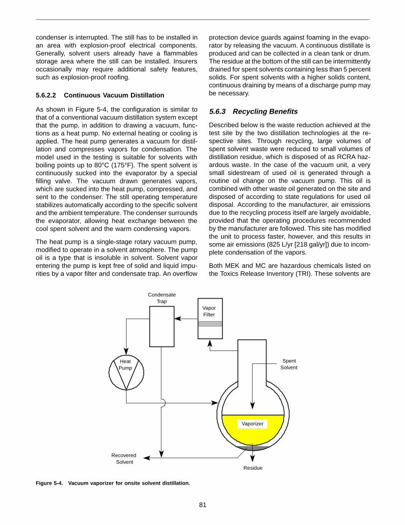
condenser is interrupted. The still has to be installed inan area with explosion-proof electrical components.Generally, solvent users already have a flammablesstorage area where the still can be installed. Insurersoccasionally may require additional safety features,such as explosion-proof roofing.
5.6.2.2 Continuous Vacuum Distillation
As shown in Figure 5-4, the configuration is similar tothat of a conventional vacuum distillation system exceptthat the pump, in addition to drawing a vacuum, func-tions as a heat pump. No external heating or cooling isapplied. The heat pump generates a vacuum for distil-lation and compresses vapors for condensation. Themodel used in the testing is suitable for solvents withboiling points up to 80°C (175°F). The spent solvent iscontinuously sucked into the evaporator by a specialfilling valve. The vacuum drawn generates vapors,which are sucked into the heat pump, compressed, andsent to the condenser. The still operating temperaturestabilizes automatically according to the specific solventand the ambient temperature. The condenser surroundsthe evaporator, allowing heat exchange between thecool spent solvent and the warm condensing vapors.
The heat pump is a single-stage rotary vacuum pump,modified to operate in a solvent atmosphere. The pumpoil is a type that is insoluble in solvent. Solvent vaporentering the pump is kept free of solid and liquid impu-rities by a vapor filter and condensate trap. An overflow
protection device guards against foaming in the evapo-rator by releasing the vacuum. A continuous distillate isproduced and can be collected in a clean tank or drum.The residue at the bottom of the still can be intermittentlydrained for spent solvents containing less than 5 percentsolids. For spent solvents with a higher solids content,continuous draining by means of a discharge pump maybe necessary.
5.6.3 Recycling Benefits
Described below is the waste reduction achieved at thetest site by the two distillation technologies at the re-spective sites. Through recycling, large volumes ofspent solvent waste were reduced to small volumes ofdistillation residue, which is disposed of as RCRA haz-ardous waste. In the case of the vacuum unit, a verysmall sidestream of used oil is generated through aroutine oil change on the vacuum pump. This oil iscombined with other waste oil generated on the site anddisposed of according to state regulations for used oildisposal. According to the manufacturer, air emissionsdue to the recycling process itself are largely avoidable,provided that the operating procedures recommendedby the manufacturer are followed. This site has modifiedthe unit to process faster, however, and this results insome air emissions (825 L/yr [218 gal/yr]) due to incom-plete condensation of the vapors.
Both MEK and MC are hazardous chemicals listed onthe Toxics Release Inventory (TRI). These solvents are
CondensateTrap
VaporFilter
HeatPump
SpentSolvent
Vaporizer
Residue
RecoveredSolvent
Figure 5-4. Vacuum vaporizer for onsite solvent distillation.
81

also on EPA’s list of 17 chemicals targeted for 50 percentreduction by 1995.
5.6.4 Economic Characteristics
The economic evaluation compares the costs of onsitesolvent recycling versus purchase of new solvent anddisposal of spent solvent.
The atmospheric distillation case study indicated thatannual solvent use decreased from 3,330 to 927 L(880 to 245 gal), and that the volume of solvent residuerequiring disposal decreased from 3,400 to 980 L(900 to 260 gal). Solvent recycling resulted in savingsof $10,011 per year. The purchase price of the atmos-pheric batch unit is $12,995. A detailed calculationbased on worksheets provided in the Facility PollutionPrevention Guide (22) indicated a payback period ofless than 2 years.
The vacuum distillation unit reduced solvent use from11,350 to 950 L (3,000 to 250 gal) per year. The solventvolume requiring disposal dropped from 11,350 to 515 L(3,000 to 136 gal). The savings due to recyclingamounted to $18,283 per year. The purchase price ofthe vacuum unit is $23,500 for the explosion-proofmodel. The payback period for this unit also was lessthan 2 years.
5.6.5 Limitations
Solvent distillation is a versatile technology that can beused in a number of different applications. The mainlimitation of this technology comes into effect if thesolvent to be recovered and the contaminants havesimilar boiling characteristics (vapor pressures). Whenthe liquids have similar boiling characteristics, simpledistillation equipment will not allow a good separation.The waste solvent would then have to be taken to anoffsite location, where facilities for fractional distillationare available.
5.7 Thermal Desorption To Treat andReuse Oily Sand
A thermal desorption (Section 3.5) unit is processingabrasive sand contaminated with diesel fuel to removethe oily contaminant and allow reuse of the treated sandas fill for new construction at the site (23).
5.7.1 Site and Waste Description
The waste matrix is an abrasive silica sand located atthe Los Angeles Port Authority San Pedro Harbor. Thesand is contaminated with marine diesel fuel that haspetroleum hydrocarbon levels as high as 30,000 mg/kg.
5.7.2 Technology Description
Sand is first screened to remove large debris, then fedthrough a counterflow kiln where it is heated to 427°C(800°F). Organics are vaporized and treated in a thermaloxidizer. The hydrocarbons also act as supplementalfuel in the oxidizer. A cyclone and baghouse filter systemcollects the fine particulates. Collected particulate isreturned to the kiln for treatment. A lining of refractoryceramic tiles has been provided in the unit’s ducting andcyclone to protect against the abrasive sand.
5.7.3 Recycling Benefits
The thermal desorption process will produce 272,340metric tons (300,000 tons) of clean sand. The sand willbe used as fill during the construction of a new containerstorage facility, thus avoiding the environmental impactand cost of disposal. Residual petroleum hydrocarbonlevels following treatment average 71 mg/kg, as meas-ured by EPA SW-846 method 8015M. The site require-ment called for reducing hydrocarbons to 1,000 mg/kgor below. To allow reuse at the site, the total polycyclicaromatic hydrocarbon (PAH) concentration must be be-low 1 mg/kg. The thermal desorption process is remov-ing PAH compounds to nondetectable concentrations.
5.7.4 Economic Characteristics
Cleanup and reuse of the soil avoids the costs for pur-chase and transport to the site of clean fill and the costfor disposal of a large volume of sand. The ceramiclining requires inspection and minor refurbishment foreach 90,780 metric tons (100,000 tons) of sand proc-essed.
5.7.5 Limitations
Thermal treatment of the desorbed organic generatessome NOx. Small amounts of particulate also are re-leased, even with the off-gas treatment filtration system.
5.8 Pumping To Recover Nonaqueous-Phase Liquids
Free product can be recovered from in situ formationsby pumping (Section 3.9) followed by decanting (Section3.4). Nine months of operation with an in situ pumpingsystem recovered more than 26,500 L (7,000 gal) ofvirtually water-free, high-Btu-content product (24).
5.8.1 Site and Waste Description
The site was a former coal gasification plant located inthe borough of Stroudsburg, Pennsylvania. Coal tar,produced as a byproduct of coal gasification, had beendischarged through trenches, wells, and the ground sur-face at the site. The site investigation indicated that upto 6.8 million L (1.8 million gal) of free coal tar had been
82

distributed over about 3.2 hectares (8 acres). The coaltar extended from the surface down to a silty sanddeposit but was not able to penetrate that layer. Anaccumulation of up to 132,000 L (35,000 gal) of nearlypure coal tar was held in a stratigraphic depression.
5.8.2 Technology Description
Coal tar was recovered using a well cluster 76 cm(30 in.) in diameter installed at the deepest point of thedepression. The cluster consisted of four wells 15 cm(6 in.) in diameter screened only in the coal tar layer andone central well 10 cm (4 in.) in diameter screened overits entire length.
Initially, coal tar was recovered by pumping from the fourwells at a slow rate. The center well was used formonitoring. About 380 L (100 gal) per day of nearly pureproduct was recovered at the start of pumping, but thewithdrawal rate declined rapidly over time.
The system was modified, as shown in Figure 5-5, toincrease the product withdrawal rate. The center wellwas modified by installing a plug at a depth between thestatic ground-water and static coal tar levels. The centralwell was then used to remove ground water. Groundwater was reinjected in a gravel-filled leaching fieldlocated about 19.8 m (65 ft) upgradient. The resultingreduction in ground-water pressure over the pumpingwell caused an upwelling of the coal tar. Cyclic pumpingof the coal tar was used, with pump operation controlledby two conductivity sensors. One conductivity sensorwas located at the maximum upwelling level and theother at the static (per pumping) coal tar level. Coal tarpumping cycled on when the coal tar level reached theupper conductivity sensor, and cycled off when pumpinghad lowered the coal tar level back to the static level.
5.8.3 Recycling Benefits
Nine months of pumping collected about 26,500 L(7,000 gal) of coal tar containing less than 1 percentwater, with a heating value of 40,700 kJ/kg (17,500Btu/lb). The recovered coal tar was used as supplemen-tal fuel and potentially could have been used as a chemi-cal feedstock.
5.8.4 Economic Characteristics
The coal tar recovery system was designed for unat-tended operations and functioned well in that mode. Themajor operating costs were electrical service for thepumps and rental fees for pumps and storage tanks.Maintenance requirements were minimal and involvedperiodic replacement of product recovery pump impel-lers and cracked polyvinyl chloride (PVC) piping. Wastedisposal was minimal due to the essentially closed-loopoperation. The operating and maintenance costs typi-cally were $1,000 per month.
5.8.5 Limitations
The most significant problem encountered during pump-ing operations was attack of well equipment by thecoal tar. The coal tar embrittled plastics such as PVCpiping, electrical insulation, and other equipment, caus-ing cracking.
5.9 References
1. New England Waste Resources. 1991. Remedia-tion saves Worcester site. New Eng. Waste Res.(March), pp. 12-13.
2. Testa, S.M., and D.L. Patton. 1992. Add zinc andlead to pavement recipe. Soils (May), pp. 22-35.
Static Ground-Water Level
Static Coal Tar Level
Depressed Water Level
Elevated Coal Tar Level
Water
RecoveredCoal Tar
LeachingField
StorageTank
Packer
Figure 5-5. Coal tar recovery system (adapted from Villaume et al. [24]).
83

3. Monroe, C.K. 1990. Laboratory investigation 88-3/59-R-323, bituminous concrete glassphaltroute 37-86. New Jersey Department of Transpor-tation, Bureau of Materials.
4. U.S. EPA. 1992. Potential reuse of petroleum-contaminated soil: A directory of permitted recyclingfacilities. EPA/600/R-92/096. Washington, DC.
5. Blumenthal, M.H. 1993. Tires. In: Lund, H.F., ed.The McGraw-Hill recycling handbook. New York,NY: McGraw-Hill.
6. ARRA. 1992. 39 ARRA contractors save the tax-payer $664,184,838.50 in 1991 (press release). As-phalt Recycling and Reclaiming Association, 3Church Circle, Suite 250, Annapolis, MD 21401.
7. Testa, S.M., and D.L. Patton. 1993. Soil remediationvia environmentally processed asphalt. In: Hager,J.P., B.J. Hansen, J.F. Pusateri, W.P. Imrie, andV. Ramachandran, eds. Extraction and processingfor the treatment and minimization of wastes. War-rendale, PA: The Minerals, Metals, and MaterialsSociety. pp. 461-485.
8. U.S. EPA. 1990. Current status of the definition ofsolid waste as it pertains to secondary materialsand recycling. Washington, DC. (November).
9. Leonard, L., A.J. Priest, J.L. Means, K.W. Nehring,and J.C. Heath. 1992. California hazardous wasteminimization through alternative utilization of abra-sive blast material. Proceedings of the 1992HAZMAT West Annual Conference, Long Beach,CA (November).
10. Bouse, E.F., Jr., and J.W. Kamas. 1988. Update onwaste as kiln fuel. Rock Products 91:43-47.
11. Bouse, E.F., Jr., and J.W. Kamas. 1988. Waste askiln fuel, part II. Rock Products 91:59-64.
12. Heath, J.C., L. Karr, V. Novstrup, B. Nelson, S.K.Ong, P. Aggarwal, J. Means, S. Pomeroy, and S.Clark. 1991. Environmental effects of small armsranges. NCEL Technical Note N-1836. Port Hue-neme, CA: Naval Civil Engineering Laboratory.
13. Perry, R.H., and C.H. Chilton. 1984. Chemicalengineers’ handbook, 6th ed. New York, NY:McGraw-Hill.
14. Wills, B.A. 1985. Mineral processing technology,3rd ed. New York, NY: Pergamon Press.
15. U.S. EPA. 1993. Technical resource document: So-lidification/stabilization and its application to wastematerials. EPA/530/R-93/012. Cincinnati, OH.
16. Queneau, P.B., and A.L. Troutman. 1993. Wasteminimization charges up recycling of spent lead-acid batteries. HazMat World 6(8):34-37.
17. Timm, S.A., and K. Elliot. 1993. Secondary leadsmelting doubles as recycling, site cleanup tool.HazMat World 6(4):64, 66.
18. U.S. EPA. 1992. The Superfund innovative technol-ogy evaluation program: Technology profiles,5th ed. EPA/540/R-92/077. Washington, DC.
19. Paff, S.W., and B. Bosilovich. 1993. Remediation oflead-contaminated Superfund sites using secon-dary lead smelting, soil washing, and other tech-nologies. In: Hager, J.P., B.J. Hansen, J.F. Pusateri,W.P. Imrie, and V. Ramachandran, eds. Extractionand processing for the treatment and minimizationof wastes. Warrendale, PA: The Minerals, Metals,and Materials Society. pp. 181-200.
20. Horne, B., and Z.A. Jan. 1994. Hazardous wasterecycling of MGP site by HT-6 high temperaturethermal distillation. Proceedings of Superfund XIVConference and Exhibition, Washington, DC (No-vember 30 to December 2, 1993). Rockville, MD:Hazardous Materials Control Resources Institute.pp. 438-444.
21. Miller, B.H. 1993. Thermal desorption experience intreating refinery wastes to BDAT standards. Incinera-tion Conference Proceedings, Knoxville, TN (May).
22. U.S. EPA. 1992. Facility pollution prevention guide.EPA/600/R-92/088. Cincinnati, OH.
23. Krukowski, J. 1994. Thermal desorber treats oilysand for L.A. port authority. Poll. Eng. 26(4):71.
24. Villaume, J.F., P.C. Lowe, and D.F. Unites. 1983.Recovery of coal gasification wastes: An innovativeapproach. Proceedings of the National Water WellAssociation Third National Symposium on AquiferRestoration and Ground-water Monitoring.Worthington, OH: Water Well Journal PublishingCompany.
84