
Handbook of The Austin Seven Book No. 352m … · Was the 14th Edition of Handbooks at that date....
23
-
Upload
nguyenlien -
Category
Documents
-
view
215 -
download
0
Transcript of Handbook of The Austin Seven Book No. 352m … · Was the 14th Edition of Handbooks at that date....

Peter R Kemp
Handbook of The Austin Seven Book No. 352m Published Mid 1926. Was the 14th Edition of Handbooks at that date. Models Covered Tourer AB Body, Scoop Scuttle, Pram Hood.
Peter R Kemp
Use Left/Right, Up/Down or Page Up /Page Down Keys To View Pages. Home or End Keys for First or Last Pages.

l.
~
,f
,~
I'
11
\;
1t
11
.
HANDBOOKOF
PRICE 2/614th EDITION
THEAUSTIN MOTOR CO. LTD.LONGBRIDGE, Nr. BIRMINGHAM
"
T,I,g"ffi'T']'phon" 'Cod,
, "SPEWILY, NORTHFIELD.", CENTRAL 4140. KING'S NORTON 230.
, BENTLEY's.
LONDON SHOWROOMS, REPAIR DEPOT AND HIRE DEPT.:
479-483, Oxford Street, W.!.(NEAR MARBLE ARCH)
T,I'g""" "AUSTINmE, LONDON:'T .!,phon, " MAYFAIR6230
Also at 3, 5 and 7, RUE du' PARNASSE, BRUSSELS.
1
1. "fm~' " "" boo'352 Mpi.", q.~' "', ..mb,',

The "AUSTIN, ~
II
j,,
, i.11
It 1
'1,1~1r" ..1.
SEVEN".
,,
I I\
~
I
".:
'.it,
2
i I.
...
CONTENTSAMMETER READINGSATTENTIONS, D,ily
W"klyMonthlyO""ion,I
BATTERY, The ...BODYWORK, Care 01BRAKES, Ad;",ting the,BRAKE GEAR, Lnhri"tion of ...BRAKES, R...lining ..,CAR. Cont<ol of the ...
" Fe,tnre, 01 the ..." The New
CARBURETTER, The
PAG'.281112131329383426369 -57
1415151525332028,28218
37262!i252719171638232119252732363527393726321030
".
Adju,tment ofSlow Running 01
" Le,hge fromCLUTCH, Luhri"tioh of ...COMBUSTION CHAMBER, CI..ning ...COOLING SYSTEMDYNAMO, The ...ELECTRICAL EQUIPMENT. TheENGINE,Luhri"tionof .
St"ting the
...
FANFRONT AXLE, Luhrication of ...
FUSE, Action of the ... '1:GEARBOX, Luhri"tion of ..'HUBS (Front ,nd Re,r), Luhri"tion 01
'IGNITION, F,ult, inRe-timingSy,tem, The
LAMPS, Care of ,..LUBRICATION CHARTLUBRICANTS ""'mmendedMAGNETO, Lubric,tion ofREAR AXLE, LubriCAtion01 ...ROAD SPRINGS, Luh,ic"ion ofRUNNING ADJUSTMENTS .'..SHOCK ABSORBERS, Adju,tment 01STEERING. Adju,tmcnt 01 ...STEERING GEAR. Luhri"tion 01TOOLS, SuppliedTYRES ...UNIVERSALJOINTS, Lubri"tion ofVALVE TAPPETS. Adju.tment 01WHEEL, How to Ch,nge ,WIRING, lItu,tr,tion of
3

THE "AUSTIN SEVEN"
THE" AUSTIN SEVEN" seats two adults and threesmal! children, or if children are not carried, a large spaceis availahle for luggage. It is not intended to carry four
adults, or weight over 30-32 stone. Everyone is brought withinthe hood, while the car is fitted with a double-windscreen, andside screens opening with the doors. It has a 4-cylinder, water-cooled engine, three-speed gearhox, and hevel drive throughdifferential. Lubrication is by pump, and cooling on thethermo-syphon system and a fan. There is an electric starter.Electric light is fitted, and spare wheel and tyre and' shockabsorbers are included in the equipment. Brakes are fitted onal! wheels, which are fitted with 26 X3t in. Dunlop bal!oon cordtyres. As the body is stove enamel!ed, the car is extremely easyto keep clean.
This little car, which can he run for about a penny a mile, isan ideal car for a woman to use herself, enabling her to do theshopping without fatigue, to visit her friends more frequently andattend social and recreative functions. Another appeal is tothe business man as it enables the executive to make the utmostuse of his time, while his expenditure is no more than it would beon tram or bus fares, and there is no need to point out the valueof such a car for the commercial travel!er, who can penetrate intodistricts which poor train services would make it hardly worthhis while to cover otherwise.
The" Austin Seven" also serves as a tender for the countryhouse. enabling a servant to go down to the village or post, or tothe doctor at any time of the day or night. without the expenseand trouhle of getting out a hig car. The speed, economy androad holding qualities of this small car place it beyond all comparisonwith the sidecar combination, and it is in addition, a thoroughlyKood job, planned and made with the car instead of the motorcycleaspect in mind.
4
,
,
..,.
r
11;
'0.'
';1.
'
I
''I11'"
;I~,,
"';t,
DIMENSIONS
ENGINE
STARTER
CLUTCH
GEARBOX.
REAR AXLE.
SPRINGS
STEERING.
FRONT AXLE
BRAKES
WHEELS
CONTROLS
PETROL TANK
LIGHTING
BODYWORK
,
Its Leading Features. Full m leng,h, 9 It. 2 in. (2,796mm.); Full m width
3 It. 10in. (1.169 mm.); Wheelb"e, 6 tt. 3 in. (1,905mm.); T"ck. 3 ft. 4 in. (1,016mm.); We;.ht. appcoX.8! cwt. (425 kg.). Ground clmance 8i in. (220 mm.!
. Four-cyl;nder water-cooled detachable head.Bore 2'2 in. (56 mm.)} . '.Stcoke. 3 in. (76 mm,) 7475 C.c"RAC. "tmg, 7 8 h.p.B"ke hom-power; 10'5 at 2,400 rev.Ign;tion: Magneto.Oil cireulation: by pump.Cooling: Thermo-,yphon with film "diator and fan.Roller ",nbhalt bming,.
. Eledrical.
. S;ngIe-plate.
. Three ,peed, forward,and mer,,; "t;ca : 4'9 '0 I, 9 to I,and 16 to I; rovem, 21 to.f ; Ball b",;ng, throughout.
. Semi-IIeating. with diflerentiaI and torque tube.Ball.bearing' and thm,t, thcoughout. F;nal drive by ,haltand helical bevel.
Semi-elliptic crca, ,pr;ng m hont.Quarter ellipt;" at rear.Shock ab,orben; are httd 10 front and r"'.
Worm and wheel, having pcovi,;on for taking up wm,
Forgd. .. H" "dion.
On all four wheel,; compemated and ea,ily adiu,tabIe.Hand brake to the fcont wheela. Foot b"k, to the re"wheel,.
Spe,;al wire detachable. fitted with 26 ;n.X 3t in. Dunlopballoon cord tyre,. One 'pare wheel with tyre.
G", lever, ;n gate, and b"ke lever. mounted eentcally.Throttle and magneto con'colleve" mounted on th, 'teer;ngwheel. Foot accelerator ;, a"o provided.
4 gallon"
By ",,-dr;ven dynamo, with accumulato" and dimmer.
. Two bucket "at, for driver aod pa..enger, that for ,hedriver being adiu,'able and that for the p""o,er beingh;o,ed to allow entranee to the rear ,eat. Rear "at tocarry two or three children. Ample '001 accommoda,ionunder "at" Spare wheel and tyre c",ied on back of car.Hood, double "'eeo, aod full,ide "reem (thoa< over ,hedoo" open with them), Electr;c horn. and ,peedometer.The Daoeb are ,'ove-enamelld for durability of fini,h andea" of cI"ning.
WORKMANSHIPAND MATERIALS, , Au,tin qu,Iity.
INSURANCE Special In,mance h" beeo anaoged at £8 IQ,. Od. per,noum.
5
.

"AUSTIN SEVEN" CHASSIS
SIDE VIEW
PLAN VIEW
"b
("
;1
,It
i
'IfJ,~
if!
'1
The NEW CAR
ON taking possession of a new car it i, advisable to giveit a general examination to see that all is complete andin order. .
Before running see that the car is supplied with fuel and water,and that the engine and gearbox have the necessary quantities 01oil. The battery should contain the required amount of acid.For quantities of oil and acid see sections" Lubrication" and,. Electrical Equipment."
Make sure that the tool. kit is complete, check it over accordingto the list given on page 39.
If you are not already familiar with Austin cars, we stronglyrecommend th~t the handbook be carefully studied.
Should the car be delivered by road it will be ready forrunning but if it has been transported by rail or overseas, theengine may have become stiff through the gumming of the oil onthe pistons. They may be freed by the injection of a little petrolinto the cylinders, through the compression plugs, and then turningthe engine a few revolutions with the starting handle.
When a car is crated for dispatch overseas, water, fuel, andoil are removed and the battery left empty and uncharged. '"
7
.
,!*
'~
Starting the EngineMake'sure that the change speed lever is in neutral position.
and the hand brake on.Turn on petrol tap at the bottom of the petrol tank (this will
be found under the bonnet).Set the engine controJlevers at the top of the steering wheel
as follows: Throttle-open about i in. Ignition-almost fully'advanced.
Give the engine a few turns with the starting handle to makesure that the crankshaft is free, then switch on. Pull out the wireon the instrument board to close the carburetter air inlet, ahd againgive the crankshaft a few sharp turns by means of the startinghandle, making sure to pull the handle upwards to commence with.Be sure to release the air shutter wire after the engine has started.
Do not try to start the engine when cold by the electric starter,It is most important that the engine be not allowed to race
when first starting liP, as time must be allowed for the oil to circulateand lubricaie various bearings.
Difficulty in starting may be caused either through suc'king toomuch petrol into the cylinder, or too little. ,I! one starts with thethrottle all but closed, a strong suction takes effect on the pilot jet,and it is seldom necessary to flood the carburetter, and in any caseit should only be flooded slightly. I! petrol is passing through thecarburetter the suction can generally be heard. ' I! the engine fail.to start and there is a good deal ofp'etrol overflowing from thecarburetter it is almost certain that the mixture getting into thecylinder is too rich. In this' case open throttle about half way.This reduces the suction effect by allowing a greater. proportion ofair to enter the engine. On firing, the engine may race away, butwill soon settle down to steady running. I! the engine does notfire, close the thiottle entirely and try again. After a stop in hotweather, failure of the engine to start is more likely to be due totoo rich a mixture than one too lean, and one should stop theengine by the switch only after quite closing the throttle. Re.startthe engine with the throttle closed. '
The car itself should never be allowed to run athigh speeds for the first 300 miles.
I! after the foregoing instructions have been carried out underthe heading of .. Starting the Engine," but the engine fails to startthe reason will probably be due to faulty ignition or carburation
Ignition: First examine the wires and see that the sparkingplugs are connected. Then test the gap of the plug points by meansof the thick end of the gauge provided in the tool kit. I! the pointsare dirty, clean them before replacing the plug. For fuller detailson the ignition system see page 16.
Carburation: The slow running jet may be stopped upor a main jet choked. Blow them out with a tyre pump. Forfuller details ahout the carburetter see page 14.
8
J
CONTROL OF THE' CARSetting of Control Levers
.. ~ FTER having started th'e engine, keep the ignition lever inthe advanced positiori; should the engine commence to.. rumhle " or run roughly, retard the lever, hut advance it
again as soon as the load on the engine is lessened. The" gas ..lever should he set generally for slow running and the. speed ofthe car controlled by the accelerator pedal.
'.1',>
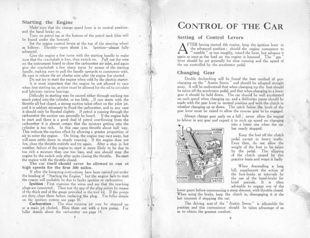
Changing GearDouble declutching will be found the best method of gear
changing on the" Austin Seven" and shonld be adopted straightaway. It will be understood that when changing np the foot shouldbe taken off the accelerator pedal, and that when changing to a lowergear it should be held down. The car should be well accelerated
, on each speed when changing up, and a deliberate pause should bemade with the gear lever in neutral position and with the clutch inwhether changing up or down. The catch below the knob of thegear lever must be raised to allow the reverse gear to be engaged.
Always change gear early on a hill: never allow the 'engirie" ,to labour in any gear and expect it to pic k up speed on changing,.~' into a lower one when the car
has nearly stopped.
Keep the foot off the clutchpedal except in heavy traffic.,Even then, do not allow theweight of the. foot to be takenby the pedal. The slippingof the clutch caused by thispractice heats and wears it badly
When descending a longhill, 'supplement the action ofthe foot.brake at intervals bythe use of thehand.brake forbrief periods. It is oftenadvisable to engage one of the
lower gears before commencing a steep descent, with throttle closed.When using the brake, keep the clutch in, disengaging it at thelast moment if stopping the car.
The driving seat of the" Austinposition and this convenience shouldas to obtain the greatest comfort.
>
/
4,f.'11
. ,D '.
(I.
"$
",,'~'.' ."'.. ~F'
*,I~). Seven" is adjustable for
be taken advantage of so
'".~
",
9

. How TOCHANGE A WHEEL
WHEN it becomes necessary to change a wheel becauseof a puncture or for any other cause. it will be necessaryfirst to remove the number plate. The spare wheel is
fastened on a bracket with three screws. in a sim;lar manner toits fixing on the hub.
To detach a road wheel from the hub loosen the three right-handthreaded nuts A which are in the hub of the wheel. by means ofthe brace; it is not. necessary to remove them entirely. Now pullthe wheel outwards about Jrin. .and turn it so that the large holewill pass over the nut. THe wheel can now he pulled 011the .bub.When replacing make sure that the large pole in tbe hub is properlyfitted over its peg.
<'.'
Should difficulty be experienced upon the first occasion ofremoving the wheel from the hub, the wheel nuts may be screwedright of!, The brake drum will then come away with the wheel.To free this from the wheel. insert a screwdriver between the twoflanges, Before replacing, wipe the outside of the brake drumand the inside of the hub with an oily rag. Great care isnecessary in order that no damage is done to the flanges. .
IQ
> PERIODICALATTENTIONS
THE importance of giving careful attentionand regular inspection to the modern auto-mobile cannot be over-estimated. If this is
done systematically considerably greater pleasurewill be derived from motoring as the car will alwaysbe kept in tune and will not require adjusting atinopportune moments.
Further, by following out the instructions givenin this book, expensive repairs may even be avoided,as much of the trouble experienced by motoristscould have been avoided if attention had been given
. to details at the proper time.
The fol1owing instructions are arranged on a daily.weekly, or monthly basis. The estimated needsof the car for such periodical attention is based. onthe assumption that the maximum mileage for aweek wi1l not exceed 300 miles.
,Daily Attentions-See also Lubrication
Chart, page 23.
1. Examine water level in radiator andfill np to within 2 in. of the top. Alwaysuse the strainer when re-filling asdirty water will cause the radiatorfilm to become choked.
2. Examine oil level in the crankcaseand add more oil if necessary. TheteJJ-tale dipper rod indicates the levelof the oH (see illustration, page 21).
Fill up the petrol tank if necessary.Care should be exercised when fillingthe tank not to spill the petrol overthe engine.
3.
11

';
Monthly Attentions
Weekly1. Examine the oil level in the gearbox
which should contain two-thirds ofa pint, or measure 2-2! in. deep.
Attentions
1. With the grease gun charge-,Front spring shackle pins (4).Rear spring pins (2).Front wheel swivel pins (2).Steering cross tube (2).Fan bearing.
as'
2. Charge the back axle case with a gunfullof grease and oil mixed half and half.
/. 3.
2. Oil the following-Handbrake gear.Pedal gear and jaw joints.Engine control. and ball joints.Clutch release ring.Rear Brake cam spindles (2).
-" 4.
Fill all the hubs withinstru'cted on page 27.
Charge with grease the steering wormcase through the connection.
grease,
Examine the battery and see that theconnections are tigh~.
6. Give a cbarge of grease to the nipple. on the fan spindle.
5.
3. Examine both sets of brakes, and adjustif necessary. For method of doing thissee page 34. Occasionally
4. Examine all bolts and nuts, and any other parts such assteering connections, neglect of which might lead to failure andbreakdown which would be followed by an expensive repair andthe inability to use the car for a lengthy period.
Inject high speed grease such asMessrs. Stern's" Diathol" into theuniversal joint at the rear end of thepropeller shaft, !md yellow grease intothe front end of the torque tube.
Oil the joints of the steering side tube.Spring clips and cylinder head nuts should be tightened
up occasionally when the car is new. and the nuts whenever thecylinder head has been recently replaced.
It is advisable occasionally to remove all the road wheels andclean inside the hub and wipe with an oily rag.
This emures the rapid removal of a wheel in case of apuncture when on the road.
5.
"Utile, but often" should be the motto in lubrication.
12 13
.
}
I
TheCARBURETTER
, Method of AdjustmentBefore altering the carburetter setting, turn off the petrol
bY'means of the tap underneath the tank. A jet key is sent outwith each car for the purpose of taking out the main and com-pensating jets. The caps below the jets must be removed bymeans of the adjustable spanner, when the 'jets can be unscrewedwith the special key. When replacing either, make sure that theyhave washers on them, and are well down on the shoulder.THE. following instructions have reference to the Zenith
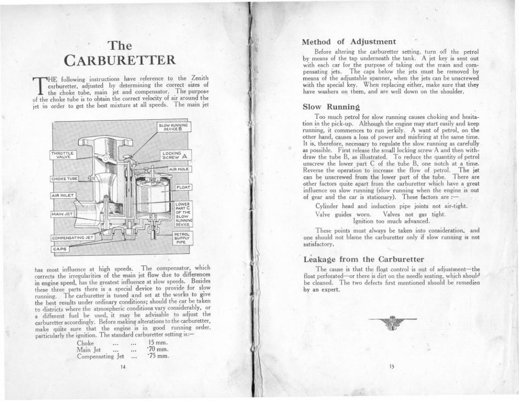
c",buretter, adjusted by determining ihe correct sizes ofthe choke tube, main jet and compensator, The purpose
of the choke tube is to obtain the correct velocity of air around thejet in order to get the best mixture at all speeds. The main jet
I
\ I
ij
jl
Slow RunningToo much petrol for slow running causes cho king and hesita-
tion in the pick-up. Although the engine may start easily and keeprunning, it commences to run jerkily. A want of petrol, on theother hand, causes a loss of power and misfiring at the same time.It is, therefore, necessary to regulate the slow. running as carefullyas possible. First release the small locking screw A and then with-draw the tube B, as illustrated. To reduce the quantity of petrolunscrew the lower part C of the tube B, one notch at a time.Reverse the operation to increase the flow of petrol. The jetcan be unscrewed from the lower part of the tube. There areother factors quite apart from the carburetter which have a greatinfluence on slow running (slow running when the engine is oulof gear and the car is stationary). These factors are:-
Cylinder head ,and induction pipe joints not air-tight.
Valve guides worn. Valves not gas tight.Ignition too much advanced.
These points must always be taken into consideration, andone should not blame the carburetter only if slow running is notsatisfactory,
i.
has most influence at high speeds, The compensator, whichcorrects the irregularities of the ,main jet flow due to differencesin engine speed, has Ihe greatest influence at slow speeds. Besidesthese three parts there is a special device to provide for slowrunning. The carburetter is tuned and set at the works to givethe best results under ordinary conditions; should the car be takento districts where the atmospheric conditions vary considerably, ora different fuel be used, it may be advisable to adjust thecarburetter accordingly. Before making alterations to the carburetter,make qtlite sure that the engine is in good running order.particularly the ignition. The standard carburetter setting is:-
Choke ... .., 15mm,Main Jet ... ,.. '70 mm,CompensatingJet ..' '75 mm.
14
. Leakage from the CarburetterThe cause is that the flo~t control is out of adjustment-the
floatperforated-or there isdirt on the needle seating, wh,ichshoul~be cleaned. The two defects first mentioned should be remedienby an expert:
1
--.-
t;
"'/
The B.L.I..G. Magneto
IN the B.L.LC. magneto the magnet rotates while the armatnre;with its Iow and high tension windings, remains stationary.
. Slip rings, long rotating brush holders, collector brush holdersand so on, have been replaced by a short stationary connectorpiece leading the high tension current from the stationary armatureto the stationary distributor terminal. The contact.breaker isalso stationary, the cam being revolved instead.
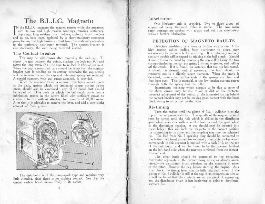
The Contact-breakerThis may be with.drawn after removing the end cap. To
adjust the gap between the points, slacken the lock.nut (C) androtate the long screw (B): be sure to re.lock it after adjustment.When the gap is measured, care should be taken that the contact-breaker base is bedding on its seating, otherwise the gap settingwill be incorrect when the cap and retaining spring are replaced.A special spanner, with gap gauge attached, is provided.
When the contact-breaker is removed, the brass contact blockat the hack, against which the laminated copper spring bladespress, should also be examined; any oil or metal dust shouldbe wiped off. The bush on which the bell.crank works has alubrication groove in the centre filled with sufficient grease toenable it to run without attention for upwards of 10,000 miles.After that it is advisable to remove the lever, and add a very slightamount of fresh grease.
...
The distributor is of the jump.spark type and reqUIres verylittle cleaning, si'1ce there is no rubbing contact. See that thecentral carbon brush moves ifeely in its socket.
16
/
J
. II~j
t
~
"1It~ik iI i
'.
11~ ~.,
1:."I!
"ti'JII
(I:.,
/
/
LubricationOne lubricator only is provided. Two or three drops of
engine oil every thousand miles is ample. The two mainrotor bearings are packed with grease and will run indefinitelywithout further lubrication.
DETECTION OF MAGNETO FAVLTSDefective insulation, or a loose or broken wire in one of the
high tension cables leading from distributor to plugs, mayoccasionally be responsible for mis hring. [t is extremely unlikelythai any trouble will be caused by sticking of the bell.crank. Shouldit occur it may be cured by removing the screw (H) fixing the twosprings displacing the hair.pin spring (]) from its groove, and pullingoff the crank. If it is found, for instance, that the pin has rusted,it should be cleaned, and, it necessary, the bush should bereamered out to a slightly larger diameter. When the crank is
. detached, make sure that the ends of the springs are clean andfree from rust. This is essential, as the Iow tension current passesthrough both the spring and the pillar.
Intermittent misfiring which appears to be due to none ofthe above causes, mav be due to oil or dirt on the contacts,incorrect adjustment 01 the points, or the laminated spring behindthe contact.breaker may not be making good contact with the brassblock owing to oil or dirt on the latter.
Re-timingTurn the engine until the piston of No. 1 cylinder is at the
top of the compression stroke. The spindle of the magneto shouldthen be turned until the hole whicb is drilled in the distributorgear wheel coincides with a similar hole behind the gear wheelin the aluminium housing. A peg should next be inserted intothese holes: this will lock the magneto in the correct positionfor conne~ting to its drive, and the coupling may then be tightenedup. The lead from N~. 1 sparking plug should be connected tothe bottom left hand distributor segment; the cable socket whichcorresponds to this segment is marked with a dash (-), on the topof the distributor, and will be found to be the opening furtheston the left. hand side when the magneto is viewed from the contact-breaker end.
The other leads should 'be connected to the re';'ainingdistributor segments in the correct firing orde" as already ascer.tained-the distributor brush revolves In the opposite directionto the rotor. Remove the peg before starting the engine. As afinal check, the timing lever may be fully retarded, when, if thepiston of No. I cylinder is still at the top of its compression stroke,it will be found that the contacts are on the point of separating,and the distributor brush is just beginning to point at distributorsegment No. I.
#.
17
Re-timing-continued.
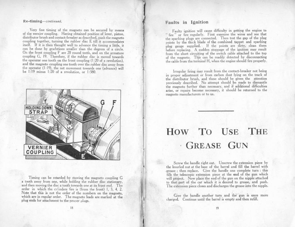
Very fine timing 01 the magneto can be secured by means01 the vernier coupling. Having obtained position 01 lever, piston,distributor brush and contact-breaker as described, push the magnetocoupling together, turning the rubber disc E till it accommodate,itsell. If it is then thought well to advance the timing a little, itcan he done by grad,tions smaller than the degrees 01 a circle.On the Iront coupling Fare 20 round teeth, and on the armaturecoupling G, 19. Therelore, il the rubber disc is moved towardsthe operator one tooth on the Iront coupling (1/20 01 a revolution),and the magneto coupling one tooth over the rubber disc away Iromthe operator (I ;19), the net movement towards one (advance) willbe 1/19 minus 1/20 01 a revolution, or 1/380.
Timing can be retarded by moving the magneto .coupling Ga tooth away Irom one, while holding the rubber disc stationary,and then moving the disc a tooth towards one at its Iront end. Thcorder in which the cylinders fire is (from the Iront) I, 3, 4. 2.Note that this is not 'the order 01 the numbers on the magneto,which are in regular order. The magneto leads are marked at theplug ends lor attachment to the proper plugs.
18
, .ij
'f
.,,:1.
t
.
or,
(
~
Faults in Ignition
Faulty ignition will cause difficulty in getting the engine to..fire" or fire regularly. First examine the wires and see thatthe sparking plugs are connected. Then test the gap 01 the plugpoints by the thick blade 01 the combined t;lppet and sparkingplug gauge supplied. If the points are dirty; clean thembelore replacing. A sudden stoppage 01 the ignition' may resultIrom the short circuiting 01 the switch cable attached to the top01 the magneto. Thjs can be readily detected by disconnectingthe cable Irom the terminal H, when the engine should fire properly.
Irregular firing <ray result Irom the contact-breaker not beingin proper adjustment or Irom carbon dust lying on the track 01the distributor brush, and these should be given the attentionpreviously described. No attempt should be made to dismantlethe magneto lurther than necessary, and il additional difficultiesarise, or repairs become necessary, it should be returned to themagneto manulacturers or to us.
How To THEUSE
GREASE. GUN
,
Screw the handle right out. Unscrew the extension piece bythe knurled nut at the base 01 the barrel and lill the barrel with
.grease ; then replace. Give the handle one complete turn: thisfills the telescopic extension piece at the end 01 the gun whichwill project. Now place the end 01 the gun on the nipple attachedto that part 01 the car which it is desired to grease, and push.The extension piece closes and discharges the grease into the nipple.
Give the handle another turn and the- g~ is once morecharged. Continue until the barrel is empty and then refill.
19

TheCOOLING SYSTEM
LUBRICATION
ONE of the following oils is recommended: Stern's Sterna IWW.. Price's Motorine C. If the oil' is too thick itwill tend to clog and carbonise, and if too thin it might
lead to scoring of the pistons and bearings. Assurance that oilis continuously circulating is given to the driver by means of thetell-tale button on the instrument board which protrudes when theoil is circulating.
ltis essential that all receptacles for oil be kept perfectly clean.Dirty pil leads to undue wear of all bearings, or might even clogup the. oilingsystem and pre-vent it war king,thus causing anengine seizure andmuch trouble andexpense. The oilfiller strainer (A)is detachable forcleaning. Addfresh oil fromtime to time asmay be required.Never pour oilinto the engi neexcept throughthe strainer.
It is advisableto change the oil in
the engine entirely after every 1,200 to 1,500 miles runningor sooner . To drain the dirty oil from the crankcase remove the plugunderneath the reservoir. This should be done while the oil ishot and sufficient time allowed for all of it to drain completely.
Every 2,400-3,000 miles remove the oil reservoir and traycontaining the strainer, carefully clean the gauze and remove all dirtfrom inside the reservoir and replace it. Carefully remake the jointwith the packing washer, covering both sides of it with gold size.See that the drain plug is screwed up tight, then fill the crankcasewith oil to the maximum level as shown on the dipper rod, B.About three pints will be required.
Always inspect the level of the oil and add, if necessary, to thecorrect level before starting on a journey. .
The Engine
THE cooling of the engine is maintained by a capacious radiatorwhich should be filled, with rain water, if available, up towithin 2 in. of the top of the filler. The capacity of the
radiator, pipes and cylinder jackets is 9 pints.
In Cold WeatherCare should be taken to see that the water is drained of!
completely, for, in case of freezing, it will do harm by lodging insmall spaces and fracture of cylinder and pipes will result. InGreat Britain, the climate does not very often call for the coolingsystem to be drained. bnt it is well to err on the right side andtake due precaution against damage if frost be threatened.
Glycerine mixed with the water will reduce its freezing pointby several degrees. It should be' added in the proportion of15% or 20%. .
In order to prevent the gradual formation of deposits in thecooling system, with consequerit impeding of the circulation, theuse of hard water should be avoided. Rain-water, syphoned fromthe top of the barrel where it is clean, should be used, or, failingthat, water that has been boiled.
Causes of OverheatingOverheating may be attributed to one or more of the following:Slack fan belt: the belt can be tightened by turning the fanspindle in its bracket after loosening the clamping-nuts.Excessive carbon deposit in cylinders. See" RunningAdjustments."Running with ignition too far retarded.Using oil of poor quality, or lack of oil in the reservoir. See.. Engine Lubrication."Partial choking of the oil jets.Improper.. carburetter' adjustment, pvmg a mixture too richor too weab See" The Carburetter."Failure of water to circulate, because of choked radiator tubes,water level below the tops of the radiator tubes,. or loss ofwater through leakage from connettions.Trouble arising from a damaged radiator generally necessitates
its dismantling and despatch to a repair depot. The entirecirculating system should be tllOroughly flushed out occasionally.To do thisJopen drain tap at bottom, place a hose in the filler, andrun fresh;';ater through.
1
,l
fI
",I
-11
It~
III20
ill
,~,',
~ ~-
.
2t

--
-
Eo<
~.(:I:0Z0.....E
o<<0.....~.~::>~
A'H
.1.NO
W110
Cl
A1W
.LN
OW
3S'9'3!1~.A
1)t33M110
0A
1)t33M3S'9'3!1~.
~N
r "-::
=- ~-=
~c-
~,""---=---.
~.:;.
:=.0-.--'.-
---
CO
"=..=
..---=
~
~.:I:'E
o<
NN
<fJ
.....<
fJ<
fJ<:I:0

zO:00-I-I-<t(.)UI.IJ-ZCZ~00(.)1-
01-I-~L&JXC)C1(1) Z<t:EV)«-V)UQ::if~«-,oLIJ-a::fXI0....
... a.~'::JQ.
>
.'«
24
.
.,
~ Tbe main bearings 01 tbe engine are 01 tbe roller type, andtbe oily vapour in tbe crankcase is quite sufficient to lubricate tbese,
Tbe pistons are also. lubricated by tbe oily vapour.Lubrication 01 tbe big-ends is ellected by catcbing oillrom tbe
pump-led jets in pockets on tbe cranksbalt webs.It is advisable to make sure tbese jets are always clear a"d' to
do so tbe plugs over tbe jets (see illustration 0" page 24) sbouldbe occasionally removed and. a piece 01 stiff wire i"serted tbrougbtbe jets, Tbis prevents loreign matter accumulati"g in tbejets a"d cboki"g tbem.Gearbox
A suitable oil for tbe gearbox is tbe same as that used in tbeengine; but illor a"y reason a"otber brand 01oil is used it sbouldbe 01 about tbe same consistency and no tbicker, otberwise it willnot reacb all tbe bearings. Tbe deptb 01 tbe oil should "everbe less tha" I i", or. more tban 2,\ in. It can be measured by arod i"serted through the filler plug hole. The maximum qua"tityis approximately ""'".pi"t. Tbe correct oil level should bemaintained; excess of oil will leak Irom tbe bearings and seriously.ffect the clutch. causing it to slip; on tbe otber band there mustbe sufficient oil to prevent wear,
The gearbox sbould be drai"ed entirely alter the /irst 500.800miles, and then alter every 4,000 or 5,000 miles, when any grit,etc., which may bave collected will drain away through tbe plughole in the sump.Clutch
The clutchsurlaces being01 a labric ma-terial must bekept Iree fromoil and grease,or the clutchwilllail to grip.It is necessaryto lubricate theoperating ringat point A, asshow" on tbesketch, o"ce aweek.
Rear AxleFor tbe rear axle attention: every 1,200 to 1,500 miles sbould be
sufficient. A mixture 01 yellow grease a"d engine oil 01 equal partssbould be used and injected witb tbe grease gun supplied witb tbe car.Do not inject too mucb grease at anyone time as tbe Ielt rings willlail to bold tbis grease in tbe axle case, and it will tben leak through0" to tbe brake drums and preve"t tbem I.rom being effective.
25
i
, I.
"
.,.
'I
I;<-
"
i)
,.
\

The makers recommend that a good quality" high-speed"grease be used. This is of a dark brown colour. and will remain inthe joint longer than the ordinary yellow grease.
The. rear universal joint being ot mctal, must be kept welllubricated at A on account of the movement of the rear axle.It should be one of the points to have strict attention. Access forgreasing this, together with the grease connection B on the endof the torque tube,is obtained througha cover C in the floorof the body, asshownon the illustrationadjoining.
Rear Universal Joint Hubs (front)-continued.
Fill the hub with greaseuntil it is seen to exude fromthe flutes, or slots, at thebase of the adaptor. It isimportant that the hubs arenot given too much grease,otherwise the brakes willnot be effective.
Hubs (rear)
,
Remove the roadwheel. Turn the wheeluntil the nipple" A" is atthe top. Inject grease intothe hub; one push down of-the telescopic extensionpiece is sufficient for or-dinary maintenance pur-poses, but when it is desired to give extra attention to the lubricationof the rear hubs the nipple can be extracted and the adaptor alreadyreferred to, inserted in its stead, the same procedure being adoptedas that described for the front.
Brake Gear
On each of therear brakes there is a.Iubricator for oilingthe cam spindlebearing. These andall other joints, etc., should be oiled once a week., The front brake cam spindle is lubricated from the swivelpin as shown at E, on illustration.Front Axle
The swivel pins are lubricated with the grease gun.
Hubs (front)Remove the road wheel. Turn the hub until the plug HA"
is at the top. Screw out the plug and screw in the adaptor illustratedwhich is provided in the kit.
Steering Gear
To obtain easy steering it is important to give it regularattention as regards lubrication. The grease gun connection ison the top of the worm case, and if a charge is given once a monthit is sufficient to lubricate the bearings of the worm and worm wheel.and also lubricate the worm itself. The bearing at the top of thecolumn, just under the steering wheel. can be given a little oil fromthe oil-can. The steering connections on the side rod and thenipples at the end of the cross rod given a charge of gr~ase oncea week.
Road SpringsThe ends of the road springs where they are attached to the
axles are provided with grease gun connections, and should begiven a charge once a week if the car is continually used. Aftera long period of use it is advisable to lubricate the leaves of thespring with a warm mixture of white lead and tallow in equal parts.This can best be applied with a stiff br~sh, the leaves being easedapart by a screwdriver; first jack up the car (not under the axles)to take the weight off the springs.
2726

ELECTRICAL EQUIPMENT
THE lighting equipment is a CAV. 6-volt system. Verylittle attention is required to keep this in satisfactory workingorder. .
Should difficulties arise that cannot be understood or remediedfrom the information given below, the difficulty should at oncebe referred to the Austin Service Department or the nearest depot.
DynamoThe dynamo should be kept" on " as a rule. It is designed
to be self-regulating, and the only parts which call for anyattention are the commutator and brushes. To examine thecommutator and brushes all that is necessary is to remove thecover. The commutator should be kept dean using a piece ofordinary soft rag. To dean a dirtv or neglected commutator, usevery hne glass paper, but this should only be done in extreme cases.Blow away anycarbon dust, seethat the carbonbrushes are wear-ing evenly, and thatthey run freely intheir slots. also thatthe flexible leadsto the brushesare not .caughtin any part ofthe brush gear.There is alubricator at eachend of the machine. A drop or two of engine oil in each, everythousand miles or so, is sufficient. The best oil to use is ordinaryengine oil. When the machines are hrst assembled the bearingsare packed with grease which lasts for a long time.
Ammeter ReadingsWhen the engine is running fairly fast and no lamps are in use,
the ammeter pointer should give a "charge" reading of 7 or8 amp., or with the lamps full on a small reading, to right or leftof .. 0," but when the engine is stopped and lamps are on, theammeter will indicate" discharge" 4-5 amp. The dimmer switchshould be used when the car is standing, even for a short time. Itreduces the discharge to a negligible figure.
If the ammeter pointer remains at 0 when the engine isrunning and no lamps are on, see that all connections are tight,particularly those on the dynamo, switchboard (F, 0, CB and CD),and cut.out, that the fuse is intact, and that the battery connectionsto switchboard are tight at both ends and unbroken. Should thereading be but a small one, see if it is necessary to dean thecommutator of the dynamo.
\-
28
'-
Action of the FuseA fuse is fitted in the switch to protect the dynam~ in the 'event
of its battery connection being broken or the battery removed.If this fuse meltslook carefully overall the batteryconnections, in-cluding thosebetween the cells,and see that noterminal is loose.Don't replace thefuse wire untilyou have foundthe fault whichcaused it to .. blow"and remedied it.
Always replace with the proper fuse wire, never using any makeshift.Reserve fuses are carried inside the cavity in the fuse cover.
Starting Motor.This unit should never require any adjustment or attention. If
for any reason it should fail to function when the battery is wellcharged, it will be necessary to remove it from the engine and sendit to the works. The armature shaft rllns in self-lubricating bushesand therefore does not require any further lubrication.
THE BATTERYThe battery is an item of the equipment that is often neglected
or receives insufficient attention. It is most important that it bekept in the best condition and the following instructions should becarefully noted.
During the winter 'months, when the periods of discharge arelong and heavy the switch on the switchboard should always be inthe out, or charging position, especially when the lights are on, andthe car is running. .
During the summer months, however, when the periods ofdischarge are comparatively light, over-charging the battery must beguarded against, as harm will result. If the car is used every day,charging for about an hour should be sufficient to compensate forthe discharge requited to operate the horn and occasionally the self-starter. It is desirable to test the specific gravity of the liquid,known as electrolyte monthly, and we strongly advise .11owners toprocure a suitable hydrometer, which can be obtained from practi-cally all good .accessory dealers-and pay particular attention to thebattery to obviate the possibility of bad results from over-charging.
Should the state of the battery be continually bad, see that all itsconnections to the switchboard are tight and unbroken, and that nowire has a chafed covering allowing leakage of current to frame.
During periods when the car is unused inspect ihe batteryoccasionally and, give it a charge if required.
29

SIDE LAMP
DYNAMO(EARTHED)
FIELI>(BLACK)
CUT OUT POSITIVE(RED)
Q
DIMMER SWITCHWITH KNOB OUTGIVESLIGHTSI>IMANDWITHKNOBIN LIGHTSfULL ON
STARTER
F.E. Frameearllred.
TAIL LAMPF.E.
-
ILLUSTRATIONOF WIRING
30
3IDE LAMP
HORN
,.
Battery-continued.
When the battery arrivesempty (as in the case of cars sent.abroad) the first thing to do isto fill and charge it.
'-..
The best indication of the
state of the battery is the densityof the liquid (known as theelectrolyt~). Its specific gravityshould be 1'275 when the batteryis fully charged and should neverbe discharged so as to bring thespeci fic gravity below 1'170,otherwise sulphating will resultand the life of the battery beshortened.
When the specific gravity istoo high, that is to say 'Yhen it.exceeds 1'275, diluted acid ordistilled water must be added.When the specific gravity fallsappreciably below n75, add. a littlepart to three of water.
sulphuric acid diluted, one
If, after being in use for some time, the battery does not seemto hold its charge properly, and the lights go dim quickly when lefton for awhile without the dynamo charging, test the acid. Shouldit be found too weak do not attempt to correct this by adding acidor water, but give a good charge and then refill with 1.275 solutionas before. The tops of the cells should be kept clean and dry,and the terminals shewed up tightly.
-.-
31

RUNNINGADJUSTMENTS
THE adjustments set out below are all that the amateur ownerwill find -necessary to make to keep the car in good runningorder, and are fully described in the following pages.
To keep correct clearance betweenTo remove and clean the cylinder
pistons, and grind in the valves.To adjust and re-line the brakes.
To adjust steering.To adjust shock absorbers.
tappets and valves.head, dean tops of the
~ Valve AdjustmentTappet
To ensure obtaining the full power of the engine, and to maintainsilence in the valve operation, it is essential to keep the tappetscorrectly adjusted. Turn the engine slowly round with the hand
starting crank. Watcheach valve open inturn and note thepoint at which its top s descending,Now turn the enginehalf a revolutionfurther to make surethat the cam is wellaway from the tappet.There should now bebetween the valvestem A and tappet
screw B a clearance equal to the thickness of the thin bladeof the" tappet clearance gauge," 11 the clearance is other thanthis it can be adjusted by loosening the lock-nut C and raising orlowering screw B, being careful to tighten up the lock-nut whenthe .,adjustment is completed. A special spanner is provided inthe tool kit for this operation-
32
I
Cleaning Combustion ChamberTo secure the maximum efficiency from the engine it is necessary
to .remove the carbon deposit that will have formed on the surfacesof the combustion chamber. This should be done after about2,000 miles running. When the cylinder head is off it may beadvisable to take this opportunity of grinding-in the valves, althoughthis will need a longer time for the work to be carried out Inany case, it is recommended that after about 4,000 miles the war kof grinding-in the valves should be undertaken.
First drain off the water through cock under the radiator,Detach the top water tube from the head. Disconnect the hightension wires from the sparking plugs. Remove the nuts holdingdown the head. Then take hold of the head at each end and liftit off: This should be fairly easy to do, and without damaging thejoint washer, which should, in the ordinary course, be in a conditionto be replaced. On no account use shellac or anything similarupon it: it will make a tight joint without. A little graphite greaseon both sides is beneficial, to prevent it sticking when the head hasnext to be removed.
When the head has been removed the valves and tops of pistonswill be exposed to view. All dirt or deposit should be removed bycarefully scraping with a sharp tool. Before grinding-in the valvesit will be necessary to remove the inlet pipe, and exhaust manifold,and carburetter, first turning off the petrol and uncoupling the pipeunder the float chamber, then disconnecting the carburetter controlrod by slipping the front end of the spring out of the hole. Eachvalve spring must be lifted by means of the special tool providedto allow the split cotter A to come out, see illustration; then removethe spring. The valve is now free to be rotated on its seat. " Alittle ~rinding compound should be smeared evenly on its f~ce,
II

~
RUNNINGADJUSTMENTS
THE adjustments set out below are all that the amateur ownerwill find -necessary to make to keep the car in good runningorder, and are fully described in the following pages.
To keep correct clearance betweenTo remove and clean the cylinder
pistons, and grind in the valves.To adjust and re-line the brakes.
To adjust steering.To adjust shock absorbers.
tappets and valves.head, dean tops of the
~ Valve AdjustmentTappet
To ensure obtaining the full power of the engine, and to maintainsilence in the valve operation, it is essential to keep the tappetscorrectly adjusted. Turn the engine slowly round with the hand
starting crank. Watcheach valve open inturn and note thepoint at which itstops descending,Now turn the enginehalf a revolutionfurther to make surethat the cam is wellaway from the tappet.There should uow bebetween the valvestem A and tappet
screw B a clearance equal to the thickness of the thin bladeof the" tappet clearance gauge," 11 the clearance is other thanthis it can be adjusted by loosening the lock-nut C and raising orlowering screw B, being careful to tighten up the lock-nut whenthe ..adjustment is completed. A special spanner is provided inthe tool kit for this operation-
32
Cleaning Combustion ChamberTo secure the maximum efficiency from the engine it is necessary
to remove the carbon deposit that will have formed on the surfacesof the combustion chamber. This should be done after about2,000 miles running. When the cylinder head is off it may beadvisable to take this opportunity of grinding-in the valves, althoughthis will need a longer time for the work to be carried out Inany case, it is recommended that after about 4,000 miles the wor kof grinding-in the valves should be undertaken.
First drain off the water through cock under the radiator,Detach the top water tube from the head. Disconnect the hightension wires from the sparking plugs. Remove the nuts holdingdown the head. Then take hold of the head at each end and liftit oft. This should be fairly easy to do, and without damaging thejoint washer, which should, in the ordinary course, be in a conditionto be replaced. On no account use shellac or anything similarupon it: it will make a tight joint without. A little graphite greaseon both sides is beneficial, to prevent it sticking when the head hasnext to be removed.
When the head has been removed the valves and tops of pistonswill be exposed to view. All dirt or deposit should be removed bycarefully scraping with a sharp tool. Before grinding-in the valvesit will be necessary to remove the inlet pipe, and exhaust manifold,and carburetter, first turning off the petrol and uncoupling the pipeunder the float chamber, then disconnecting the carburetter controlrod by slipping the front end of the spring out of the hole. Eachvalve spring must be lifted by means of the special tool providedto allow the split cotter A to come out, see illustration; then removethe spring. The valve is now free to be rotated on its seal..' Alittle ~rinding compound should be smeared evenly on its f~ce,
II

Cleaning Combustion Chamber-continued.
and the valve rotated hackwards and forwards, advancing it a stepat short intervals until the pitting is removed. Care should hetaken that none of the compound enters the cylinders, and thevalve and seating should he wiped clean after the operation.When replacing the head take care to tighten the nuts evenly.Don't forget, after replacing the head, to refill the radiator.
Adjusting the Brakes
The hand hrake operates on the front wheels and the bothrake'on the rear wheels. They require adjusting when the handlever can he pulled right hack to the full travel on the'rack, andwhen the pedal can he pushed nearly to the floor hoard withouteither hrake holding the wheels. The car should never he taken
out when in this conditionhut attended to at once. .
To adjust the hand hrakepull the lever on ahout o;'e-third(or to suit driver's reach) ofthe total travel provided hythe rack. Now unlock thenut B and screw up thehrake adjusting handle A u ntiIthe shoes are hard on, thedrum. If the hrake sho~s donot then ruh on the drum whenthe lever is right forward. theadjustment is correct. Seethat the handle is locked againhy nut B.
To adjust the foot hrake: Underthe car and approximately underthe fuot controls is a wing nut
C. This must hescrewed towards thefront of the engineuntil the brakesgo full on whenthe pedal is de-pressed ahout 2 in.When the pedal isup, the hrake shoesshould not rubthe rear wheeldrums in whichthey operate.
Adjustment of SteeringIf after continual use slackness should be felt in the steering.
two adjustments are availahle :-1'0 take up the play in thecolumn, loosen the nut which tightens the bracket supporting thesteering outer column to the instrument board, unscrew locking peg" A" and clamping holt .. B." then turn the sleeve" C" withthe special spanner provided for the purpose, until the play hasheen removed. Do not screW the sleeve in t06 tight or thesteering will then become stiff. Having adjusted the sleevecorrectly, 'screw in the locking pcg so that it enters one of the slotsof the sleeve, tighten up the clamping halt, and the supportinghracket to the instrument hoard. '
,.,'
34
To take up the clearance hetween the worm and worm wheel,due to wear, slacken the three nuts" 0" holding the cover" E "to the worm casing, then turn adjusting screw" F .. so as to slightlydraw the cover in the direction of the worm, Care must he takenthat the worm wheel is not hrought too tight into mesh with theworm or it will make the steering exceedingly hard and stiff. Havingmade the adjustment he sure and tighten up the three nuts" D."
Should it he desirahle to remove the steering worm wheelfrom the casing, it is only necessary to slacken the "djusting screwF and remove the three nuts 0 when the cover E can he withdrawntogether with the worm wheel and steering arm, The steeringcolumn H with control rods can he withdrawn hy first removingcontrol levers K and nut L, then slacken lockiIl~ peg A andclamping halt B and, unscrew the sleeve C.
35
~

If
Re-lining BrakesIt is necessary first to remove the wheel and brake drum.
To enable the ends of the springs to be released from theshoes, slots are provided in Ihe brake linings. With a screw driver
Adjustin~ Austin Front Shock Absorbers-continued,
The frictional resistance required to effectively control theaction of the springs is comparatively small, and care should betaken not to decrease the pressure, when adjusting, more than isabsolutely necessary in order to obtain the desired results.
In the case of fast sporting cars and for road and track racing,a considerable increase in pressure may, of course, be required.
When adjustment does become necessary, carefully note theriding qualities of the car, and if the spring action seems tooretarded or stiff, reduce the frictional resistance of the shockabsorbers by turning the centre adjusting nut to the left, or counter-clockwise, after slac kening the lock nut, If the spring action seemstoo free, increase the frictional resistance by turning the adjustingnut to the right, or clockwise.
Careful adjustment in this manner will produce an ideal con-dition. The spring will still have the required amount of flexibilityfor easy riding, but spring vibration will be reduced to a minimumand violent rebound effectively eliminated,
,"'.'or similar tool the hooked ends of the springs can be forced up thegrooves till they become detached from the brake shoes, which canthen be taken out for re-lining. When replacing the shoes the endsof the springs should be pulled into position by means of a pieceof thin wire looped round the hooks, and threaded throughthe slots,
Rear Shock Absorbers.
The rear Austin shock absorbers do not require adjustment..'J'
Adjusting Austin Front Shock AbsorbersThe shock absorber is set to a certain initial tension before it
leaves the factory, and no change in this adjustment should benecessary for a very considerable time.
Re-adjustment may only become necessary after severalthousand miles of car travel, and should be made only when thespring movement seems too retarded or too free, It should benoted that the full benefit of the shock absorbers will not be feltwhen the car is travelling at low speeds, as under these conditionsthe spring movement is very limited, but as the speed increasestheir effect becomes more pronounced, especially over bad roadswhen the spring action is most severe. Testing should thereforebe carried out at comparatively high average touring speeds andadjustment made to suit these conditions,
Fan Adjustment.
Release the clamping pin nut on the fan bracket and thenturn the spindle, which is in the form of a crank, until the necessarytension is obtained,
Tyres
4As tyres form such a large item in the running costs of a car
it is advisable to give them periodical examination and attention,
j'If they have become badly cut, they should be removed and
repaired as soon as possible,
36I 37

CARE OF BODYWORK
To preserve the good appearance of the car wash theexterior frequently. It is advisable to remove mud andd"st Irom the bodywork directly the car returns from a
run. This should always be done by the use of cold water.either through a hose or syringe, in conjunction with a welsponge. On no' account rub of! the mud. Do not apply thewater with too much force. and keep it away from the cornersand joints. etc.. so that it will not be forced inside the body. Afterthoroughly washing and rinsing, finish with a chamois leather. Donot use the same sponge and leather for the chassis parts.
Care should be taken in. folding down the hood to see thatthe original folds are used. Should the car have been used inwet weather leave the hood up to dry. Never fold it when wet.
The metal plated parts can be cleaned with ordinarymetal polish.
Should the car be laid up in the garage for long periods. theluel and water should be drained of! and the batteries removed.and weight taken off the tyres.
CARE LAMPSOFSee that the lamps are correctly set-that is. pointing
slightly downwards. Much of the dazzle caused during nightdriving is due to carelessly set lamps and the offside lamp shouldso be set that its beam is not cast directly into the driver's eyesof any approaching vehicle. ,
Remcmber that the rellector is an optical instrument andnot part of the metal work of the car. and should never be cleanedwith patent metal polishcs.or brick-dust and paraffin. If it isdull or scratched. its efficiencywill go. and when a rellector is inthis condition. it pays to return it to the makers to be ,eplated andrepolished. Special cleaning cloths should be kept for rellectors.and these should be used for nothing else. The efficiencyof thelamps depends almost entirely on the reflectors. Special treat-ment is necessary to preserve the high optical finish. The lampsare themselvesboth dust-tight and water-tight; cjntinued cleaningtherefore. is not necessary. /'
The lamp bulbs lor C.A.V. lighting set are No. 65 and thoselor Howse and Burley sets are" Mazda .. No. 2. The bulb forthe tail lamp in each case is No. 74.
38
I
I
I
.
TOOLS! in. and i\- in. box spanner.~in. anJ i in. box spanner.,., in. and! in. double open-
end spanner.i\- m. and i in. double open-
end spanner.ir in. and! in. double open-
cnd spanner.Adjustable spanner. 4 in.Carburetter jet key.Hub-cap dnd steering column
sleeve spanner.Magneto spanner.Tappet adjusting spanner.Spanner for dynamo casing
nut.
SUPPLIEDTool wrap.Sparking-plug box spanne. and
tommy bar.Brace for detachable wheel..Tyre levers. .Tyre pump.Lifting jack. with handle.Screwdriver.Sparking plug and tappet
clearance gauge.Grease ~un.Valve-spring lifter.Trade-mark cleaning plate.Adaptor for front and rear hub
greaser.
A spare cylinder.head gasket is also supplied.
"THE ADVOCATE"THE AUSTIN CAR OWNERS' MAGAZINE
Invaluable for helpful adviceand interesting motor articles.
51-.per annum. Post free anywhere.
--y-
39

,
-
11"<::
.~~"s,0
~~'
..",..",'"
-,'!!cE0EV2:
-~
""
i2!'"u"
c';"
."."
-..J.t;
".
:§s
"E
uc>
:Q
-.


